


FP-3500T/3600T/3650T
)376HULHV
User Manual
8VHU0DQXDO
Series

Preface
Thank you for purchasing Digital’s TFT type color display panel, the ‘FP-3900T series’ (hereafter referred to as the FP
unit).
Please read this manual completely to insure the correct use and complete understanding of the FP unit’s functions.
NOTICE
1. Copying this manual’s contents, either in whole or in part, is prohibited without the express permission of Digital
Electronics Corporation, Japan.
2. The information contained in this manual is subject to change without notice.
3. If you find any errors or omissions in this document, please contact Digital Electronics Corporation to report your
findings.
4. Please be aware that Digital Electronics Corporation shall not be held liable by the user for any damages, losses,
or third party claims arising from the uses of this product.
Product names used in this manual are the trademarks / registere d trademarks of their respective owners.
© 2007 Digital Electronics Corporation. All rights reserved.
1
Essential Safety Precautions
This manual describes safety instructions for correct use of the FP unit. Pl ease keep this manual cl ose at hand and refer to
it when necessary.
Safety Icons
Throughout this manual, these icons provide essential safety information for FP operation procedures requiring special
attention. These icons indicate the following levels of danger:
Indicates situations where severe bodily injury, death or major equipment
damage can occur.
Indicates situations where slight bodily injury or minor equipment damage can
occur.
Indicates actions or procedures that should NOT be performed.
Indicates actions or procedures that MUST be performed to ensure correct
unit operation.
Because of the ever present danger of electrical shock, be sure to unplug the power cab le from the FP unit before
plugging the cable’s other end into the wall.
Do not use power in excess of the unit’s specified voltage range since it may cause a fire or electric shock.
Because the FP unit contains high voltage parts, an electric shock can occur when disassembling the unit. Therefore,
be sure to always unplug the unit before disassembling it.
Do not modify the FP unit in any way, since it may cause a fire or electric shock.
Do not use touch panel keys to perform life-threatening or vitally important safety functions. Use separate mecha nical switches for such keys.
Do not use the FP unit as a warning device for critical alarms that can cause serious operator injury, mac hine damage
or production stoppage. Critical alarm indicators and their control/activator units must be designed using stand-alone
hardware and/or mechanical interlocks.
2
In a situation that a detection function for the backlight burnout has been ineffective, if a burnout of the backlight
happened, unlike in an extinction condition of the backlight of FP, the touch panel is still active. If an operator fails
to notice that the backlight is burned out and touches the panel, a potentially dangerous machine miss-operation can
occur. Therefore, do not set up switches on the touch panel of an FP that are likely to cause human error or physical
damage triggered by mis-operation.
If your FP’s backlight suddenly turns OFF, use the following steps to determine if the backlight is actually burned
out.
1) If your current FP application or Auto off Disp fu nction is not set, and the screen has gone blank, your backlight is
burned out.
2) If your current FP application or Auto off Disp function is set, and if touching the screen does not cause the display to reappear, your backlight has been burned out.
If substantial amounts of metallic dust, water or liquids enter the FP unit, turn off the power supply immediately,
unplug the power cord, and contact your local FP distributor.
When installing the FP unit, be sure to follow the instructions given in “Chapter 3 Installation and Wiring,” to insure
it is done correctly.
Do not use the FP in an environment with flammable gas, since it may cause an explosion.
The FP is not appropriate for use with aircraft control devices, aerospace equipment, central trunk data transmission
(communication) devices, nuclear power control devices, or medical life support equipment, due to these devices’
inherent requirements of extremely high levels of safety and reliability.
When using the FP with transportation vehicles (trains, cars and ships), disaster and crime prevention devices, various types of safety equipment, non-life support related medical devices, etc, redundant and/or failsafe system
designs should be used to ensure the proper degree of reliability and safety.
Do not press the screen’s touch surface too strongly with either your finger or a hard object, since the touch surface
may be damaged.
When the surface of the display screen becomes dirty or smudged, clean the display with a cloth soaked in a neutral
detergent. Do not use paint thinner or organic solvent.
Do not press on the touch panel's face with sharp objects, such as a mechanical pencil or screwdriver, since it might
damage the LCD panel.
A void using or storing the FP in direct sunlight, excessivel y dusty or dirty environments, or where c hemical s or their
vapors are present in the air.
3

Avoid restricting the FP’s natural ventilation, or storing and using the FP in an environment that will increase the
FP’s internal te mperature.
Do not use the FP in areas where sudden, large changes in temperature may occur. These changes can cause condensation to form inside the unit, possibly causing an accident.
Do not store or use the FP where chemicals (such as organic solvents, etc.) and acids can evaporate, or where chemicals and acids are present in the air.
When the product is disposed of, it should be done so according to your country’s regulations for similar types of
industrial waste.
LCD Panel Usage Precautions
Notes on the FP’s Liquid Crystal Display (LCD)
For detailed LCD information, please contact Digital’s Development department, Product Quality Assurance group.
• The FP’s LCD contains a strong irritant. If the panel is damaged and the LCD unit’s liquid contacts your skin, be sure
to wash it with running water for at least 15 minutes. If any of this liquid should enter your eye, be sure to flush the
eye with running water for more than 15 minutes, and see a doctor immediately.
• The FP unit’s LCD screen may flicker or show unevenness in the brightness of certain images or at some contrast
settings. This is an LCD characteristics and not a product defect.
• There’s an individual difference in brightness and tone of LCD screen. Please be aware of this difference before using
the lined-up plural units.
• Some of FP unit's LCD screens may contain black and white colored pixels. This is an LCD characteristic and not a
product defect.
• The displayed color will look different when viewed from an angle outside the specified view angle. This is also
normal.
• Displaying a single screen image for long periods of time can cause an afterimage to remain. To correct this, turn the
unit OFF for 5 or 10 minutes, then turn it ON again. This phenomenon is a common attribute of the LCD unit’s, and
not a defect. To prevent this effect, you can:
- use the Display OFF feature, if the same image is to be displayed for a long period of time.
- change the screen display periodically to prevent the displaying of a single image for a long period of time.
4

Connecting the FP to a PC
The FP-3900TSeries units are designed as a standard SXGA display.
Be aware that some types of SXGA equipment may not be within the ranges specified in this document, and, therefore,
cannot be connected to the FP.
Also, if you change your PC’s SXGA board, there is the possibility that the new board may not be able to be connected to
the FP.
SEE
2.3 Interface Specifications (page2-5)
• When a signal timing value not compatible with this device is entered, or if the
entered timing is larger than can be displayed by the dot clock, an “Out of range”
message is displayed. If this occurs, be sure to read your computer’s manual
and enter a value that is compatible with this device.
• If no signal (synchronized signal) is entered, a “No signal” message is displayed.
5
This manual uses the following icons:
Indicates a warning or a product limitation. Be sure to follow the instructions
given with this icon to ensure the safe operation of the FP.
Contains additional or useful information.
Information Symbols
(1) (2)
*1 Indicates useful or important supplemental information.
SEE
FP Series Indicates a generic name for the products of .
Indicates steps used to accomplish a given task.
Be sure to follow these steps in the order they are written.
Indicates pages containing related information.
FP-3900T Series Models
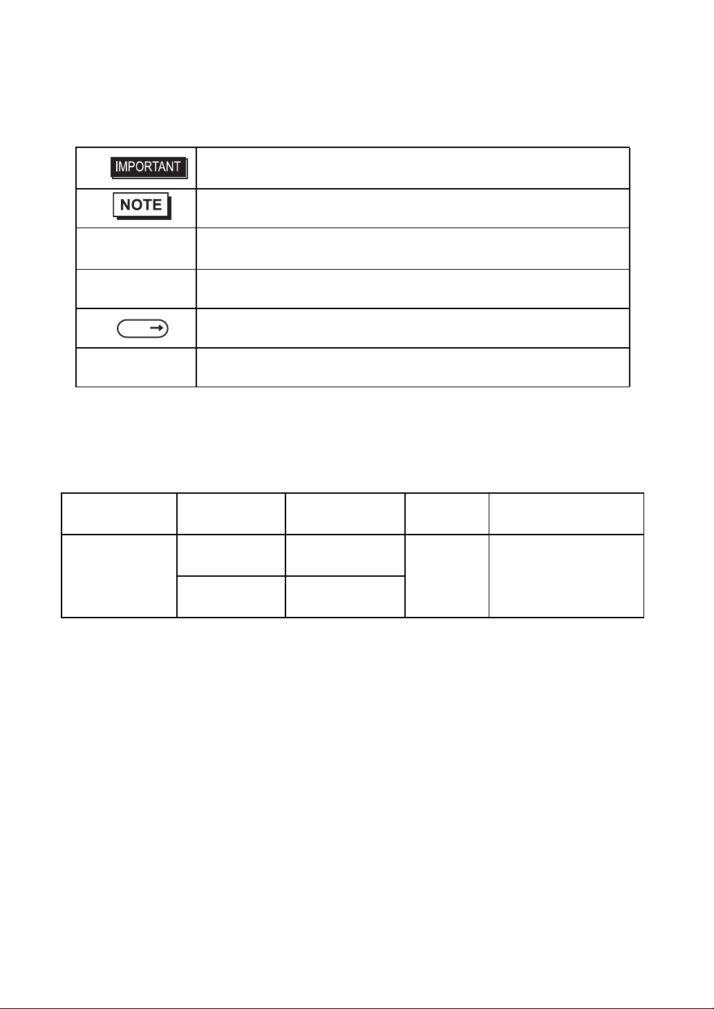
The FP-3900T Series refers to the following FP model numbers:
Series Product Name Model Type
FP-3900T
(with front USB)
FP-3900T Series
FP-3900T
(no front USB)
FP3900-T41-U
FP3900-T41
Power input
type
AC
Standards
UL/c-UL/CSA Approved,
CE Marked
6
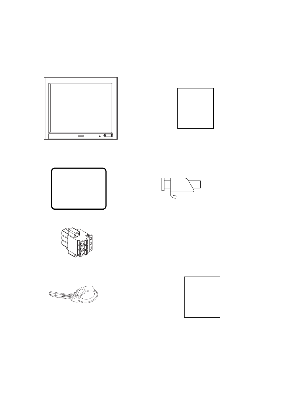
FP-3900T Series Package Contents
The FP unit’s packing box contains the items listed below. Please check to be sure each item is included and is not damaged.
FP Unit (1) Installation Guide (1)(English / Japanese)
Installation
Guide
(This model is FP3900-T41-U )
Installation Gasket Installation Fasteners (12: 4×3 set)
(attached to the FP unit) (1)
AC Power Connector(atached to the FP unit) (1)
USB Cable Clamp (1) Warning Caution Information (1)
Warning/Cau-
tion
Information
This unit has been carefully packed, with special attention to quality. However, should you find anything damaged or
missing, please contact your local FP distributor immediately.
7

Main Features
FP-3900T series displays are equipped with the following features.
• High Quality TFT Color LCD Display
This unit is equipped with a 19.0 inch TFT type color LCD. Its superior brightness and wide viewing angle, not found
in ordinary laptop-type TFT LCDs, widens your scope of applications.
The screen's maximum resolution is 1280 × 1024 pixels and can display 1,677 colors.
• Easy Installation In User’s Cabinets and Panels
The FP’s slim and compact design makes in st allation a snap since it was designed specifically for use as an IA (Industrial Automation) or OA (Office Automation) system monitor. The flat, front panel provides protection equivalent to
the rigorous IP65f standard. Even without its optional protective cover the front panel is highly resistant to both water
and dust.
• Panel can be used as a VGA Display
Since the FP is equipped with an analog RGB interface and a DVI-D Interface, it can be connected to a PC and other,
similar devices. (The PC’s dot clock frequency, however, must be within the standard range.)
• Easy-to-use Built-In Touch Panel
The FP’s built-in touch panel is standard equipment, allowing touch panel data to be output to a host PC via an RS232C cable or USB cable. This is perfect for systems requiring both touch panel operation and data monitoring.
• USB-HUB function (Model T ype:FP3900-T41-U)
The FP-3900T unit has USB-HUB function and can connect USB devices to the front USB connector.
8
What is IP65f?
This unit’s protection rating of IP65f is actually a composite code, consisting of the internationally recognized British
“Ingress Protection” standard (BS EN 60529:1992) - “IP65”, and the standard developed by the Japanese Electronics
Manufacturer’s Association (JEM) - “f”. This code is used in this manual to identify a given product’s degree of structural
resistance to a variety of environmental elements and thus, prevent problems or accidents related to the inappropriate use
of a product. The individual meaning of each character of this code is explained below.
IP 6 5 f
(1) (2) (3) (4)
(1) Designates the type of protection provided.
Indicates the degree of protection provided to the human body by the unit, and the deg ree of
(2)
protection provided by the unit's front face from particles/dust intrusion into the interior of the
unit. Here, “6” indicates that the unit is completely protected from dust intrusio n.
Indicates the degree of protection provided by the unit’s front face from water intrusion into
(3)
the interior of the unit. Here, “5” indicates that the unit is protected from water intrusion from
a direct water jet.
Indicates the degree of protection provided by the unit’s front face from oil particle intrusion
(4)
into the interior of the unit. Here, “f” indicates that the unit is co mpl e tely protected from oil
intrusion via either oil particles or oil splashes from any direction (to the front panel).
Required Software /Reference Manual
An FP-3900Tseries unit needs the following software for operation. As the FP user manual, provided by PDF media,
describes its details, download the manual below and get the further information. Vi sit our support site below and get both
software and reference manual.
Digital Electronics Corporation’s support site - Otasuke Pro!
http://www.pro-face.com/otasuke/
• Software: Mouse Emulation Software
• Manual: FP-3900T series User Manual
• For use of USB for sending touch data, the number of the calibration point of
mouse emulation software should be 9. (The initial setting is 4.)
If you don't change the setting values, the touch position may not be accurate, a
little off the point.
9

UL/c-UL/CSA Approval
FP-3900T Series is a UL/c-UL/CSA listed product. (UL File No.E220851, CSA File No. 219866)
Those products conform to the following standards:
• UL508 Industrial Control Equipment
• CSA-C22.2, No.142-M1987 Process Control Equipment
Product Model No. UL Registration Model No.
FP3900-T41-U
3582701-01
FP3900-T41
.
<Cautions>
• The FP must be used as a built-in component of an end-use product.
• This unit should be installed in the front face of a metal panel.
• If this unit is installed so as to cool itself naturally, be sure to install it in a vertical panel .
Also, be sure that the FP unit is mounted at least 100 mm away from any adjacent struct ures or equipment. If these
requirements are not met, the heat generated by the FP unit’s internal components may cause the unit to fail to meet
UL/c-UL standard requirements.
• For use in Polluition Degree 2 environment
• For use on a flat surface of a Type 1 Enclosure.
10

CE Marking
The FP-3900T Series is a CE marked product that conforms to EMC directives and Low Voltage directives EN55011
Class A, EN61000-6-2 and EN60950-1 First Edition.
*For detailed CE marking information, contact your local FP distributor.
11

MEMO
12

Table of Contents
Preface...........................................................................................................1
Essential Safety Precautions ........................................................................2
Connecting the FP to a PC ...........................................................................5
Information Symbols .....................................................................................6
FP-3900T Series Models ..............................................................................6
FP-3900T Series Package Contents .............................................................7
Main Features ...............................................................................................8
What is IP65f? ...............................................................................................9
Required Software /Reference Manual .........................................................9
UL/c-UL/CSA Approval ...............................................................................10
CE Marking .................................................................................................11
Table of Contents .........................................................................................13
Chapter 1 Introduction
1.1 System Design................................................................................................1-2
1.2 Optional Equipment........................................................................................1-3
Chapter 2 Specifications
2.1 General Specifications....................................................................................2-2
2.1.1 Electrical specifications.........................................................................................2-2
2.1.2 Environmental specifications ................................................................................2-2
2.1.3 Structural specifications........................................................................................2-3
2.2 Functional Specifications........................... ........... .......... ........... .....................2-4
2.2.1 Performance ........................................................................................................2-4
2.2.2 Display..................................................................................................................2-4
2.3 Interface Specifications...................................................................................2-5
2.3.1 Analog RGB Interface...........................................................................................2-5
2.3.2 DVI-D Interface.....................................................................................................2-7
2.3.3 Serial Interface......................................................................................................2-9
2.3.4 USB Interface (Up-stream port).........................................................................2-10
2.3.5 Front USB Interface (Down-stream port)(FP3710-T41-U model only)...............2-11
2.4 Cable Diagrams............................................................................................2-12
2.4.1 RGB Interface Cable Pin Connections (Option cable: VGA standard) ...............2-12
2.4.2 DVI-D Interface Cable Pin Connections (Option cable)......................................2-13
2.4.3 SIO Interface Cable Pin Connections.................................................................2-14
2.4.4 USB Interface Cable Pin Connections................................................................2-14
2.5 Names and Functions...................................................................................2-15
2.6 Dimensions...................................................................................................2-16
13

2.6.1 External Dimensions..... ... .... ... ... ... .... ... ... ... ... .... ... ... ... .........................................2-16
2.6.2 Dimensions with installation fasteners................................................................2-17
2.6.3 Dimensions with Cables............................. ... .... ... ... ... .... ... ... ... .... ... ... ... ...............2-17
2.6.4 Installation Fasteners . ... .......................................... ... .... ... ... ... .... ... ... ... ... ............2-18
2.6.5 Panel Cut Dimensions ........................................................................................2-19
Chapter 3 Installation and Wiring
3.1 Installation.......................................................................................................3-2
3.1.1 Installation Procedures ........................... ... ... .... ... ... ... .... ... ... ... .... ... ... ....................3-2
3.2 Wiring..............................................................................................................3-7
3.2.1 Connecting the Power Cord . ... ... ... .......................................... .... ... ... ... ... .... ... ... ... .3-7
3.2.2 The USB Cable Clamp...................................... ... ... ... .... ... ... ... .... ... ... ... ... .... ... ... ... .3-9
3.2.3 Connecting the Power Supply.............................................................................3-10
3.2.4 Precautions: Grounding.................... ... ... ... .......................................... ... .... ... ... ..3-11
3.2.5 Precautions: Input/Output Signal Lines...............................................................3-11
Chapter 4 Setting up and Adjusting the FP unit
4.1 Operation Mode Setup....................................................................................4-2
4.1.1 Preset Settings and Adjustments for Dip Switch and Slide Switch.......................4-2
4.1.2 Status of Front LED in Operation Modes..............................................................4-3
4.2 Screen Display Adjustment.............................................................................4-4
4.2.1 Calibration of OSD Display Position .....................................................................4-4
4.2.2 OSD Setting Icons ................................................................................................4-6
4.2.3 OSD Setting Item Details......................................................................................4-7
Chapter 5 Touch Panel Data
5.1 Touch Interface Data....................................................................................... 5-2
Chapter 6 Troubleshooting
6.1 Troubleshooting.............................................................................................. 6-2
6.1.1 Possible Device Problems ....................................................................................6-2
6.1.2 No Display.................................. ... .... ... ... .......................................... ... .................6-3
6.1.3 Touch Panel Does Not Respond................... .... ... ... ... .... .......................................6-5
6.2 Error Message................................................................................................6-6
6.2.1 Error Message List................................................................................................6-6
Chapter 7 Maintenance
7.1 Regular Cleaning............................................................................................ 7-2
14

7.1.1 Cleaning the Display................... .... .......................................... ... ... ... ... .... ... ... ... ...7-2
7.1.2 Installation Gasket Replacement..........................................................................7-3
7.2 Periodic Check Points.....................................................................................7-4
7.3 Backlight Replacement...................................................................................7-5
15

MEMO
16

1 Introduction
1. System Design
2. Optional Equipment
This chapter describes the outline of FP Series.
1-1
FP-3900T Series User Manual
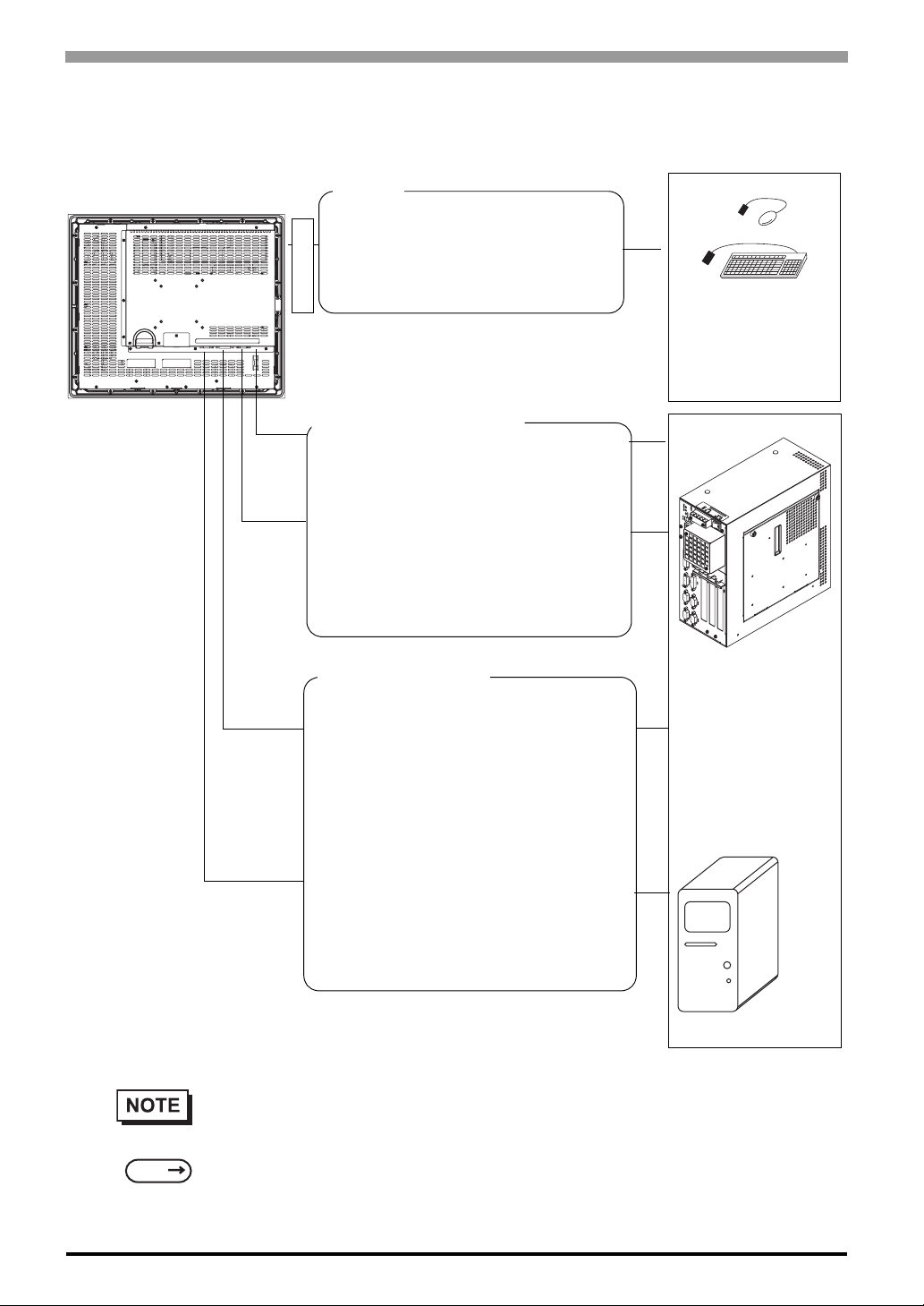
1.1 System Design
The FP can be connected to Pro-face’s PS-2000B or to a Windows® compatible PC.
FP unit
USB I/F
For downstream port of FP’s embedded
USB-HUB
(Type-A connector)
*FP3900-T41-U only
Front Side
Touch Panel transmission
For Touch data transmission
USB Cable (FP-US00<5m>)
(A-B type Cable)
Or
RS-232C Cable(FP61V-IS00-O<5 m>)
Straight Cable: Dsub 9-pin female
Image Signal Output
For image signal output
DVI-D Cable
(FP-DV01-50 <5 m>, FP-DV01-100 <10 m>*)
(XGA standard: DVI-D 24-pin)
Peripherals complied
with USB2.0/1.1
(Commercial products
such as USB
keyboards)
PS-2000B or
Windows
PC
®
Compatible
1-2
SEE
Or
Analog RGB Interface Cable
(FP-CV02-45<4.5m>)
XGA standard: Dsub 15-pin male
* The FP-DV01-100 can be used only when
connected to a PS-2000B unit. Available
display resolution is 1024 × 768 (XGA only).
• The FP unit’s slide switches set the type of cable(s) used for sending touch data (USB or
RS232C).
4.1.1 Preset Settings and Adjustments for Dip Switch and Slide Switch (page4-2)
1.2 Optional Equipment
All optional items listed below are products of Digital Electronics Corporation.
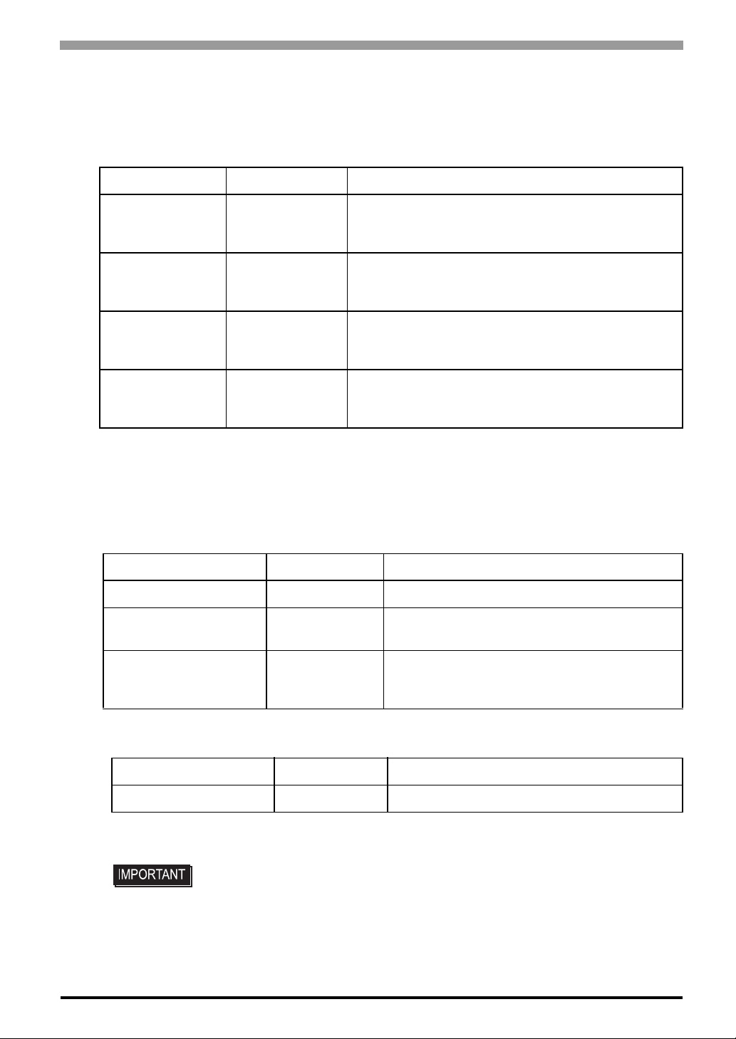
Cables
Product Name Model No. Description
RS-232C Cable FP61V-IS00-O
USB Cable FP-US00
Analog RGB Cable FP-CV02-45
Chapter 1 Introduction
Serial interface cable (5m) used for touch panel data
transmission between the host and the FP. This is a
straight Dsub9 pin female cable.
USB interface cable (5m) used for touch panel data
transmission between the host and the FP. The cable
type is A-B.
Analog RGB interface cable (4.5m) when image signal
is output to the FP from the host. VGA specifications
(Dsub15 pin male). (4.5m)
DVI-D Cable
*1 The FP-DV01-100 can be used only when connected to a PS-2000B unit. When using
the FP-DV01-100, be sure to turn the PS-2000B’s internal dipswitch 4 ON.
(When using the FP-DV01-50, turn this switch OFF.)
Maintenance Parts
Product Name Model No. Description
Installation Fasteners CA3-ATFALL-01 Metal installation fasteners.
Rubber Gasket CA7-WPG19-01
Screen Protection Sheet CA7-DFS19-01
FP-DV01-50
FP-DV01-100
*1
Digital Visual Interface cable used to send the image
signal from the host to the FP. XGA specifications (DVID 24-pin male). (5 m or 10 m)
Replacement rubber gasket, used when installing
the FP. Same as the FP's original gasket.
Disposable and dirt resistant sheet for the FP's
screen. The FP's touch panel can be used with
this cover sheet attached. (5 sheets/set)
Related Software
Product Name Model No. Description
Mouse Emulator
*1
UPDD Mouse Emulator software for the FP
*1 OS can be Windows NT®4.0 SP6A or higher, Windows®2000 or Windows®XP.
• Visit our support site below and download the mouse emulation software (UPDD).
Digital Electronics Corporation’s support site - Otasuke Pro!
http://www.pro-face.com/otasuke/
1-3

FP-3900T Series User Manual
MEMO
1-4

2 Specifications
1. General Specifications
2. Functional Specifications
3. Interface Specifications
4. Cable Diagrams
5. Names and Functions
6. Dimensions
This chapter describes the general, functional and interface spe ci fications of the FP as well as its part names
and dimensions.
2-1
FP-3900T Series User Manual
2.1 General Specifications
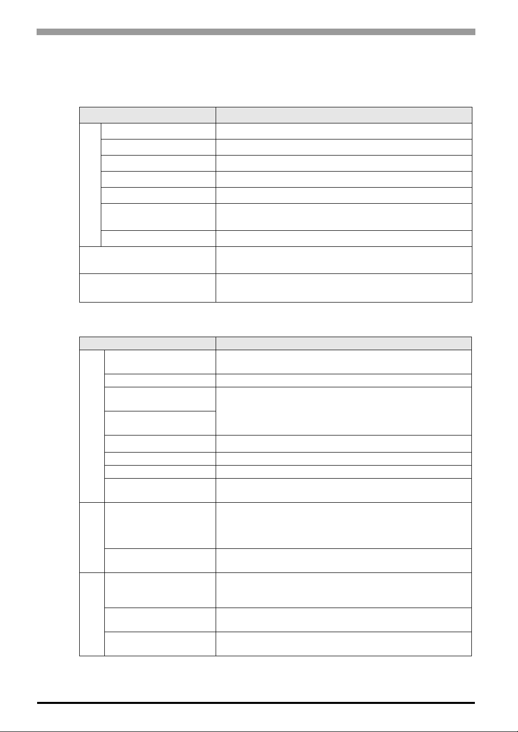
2.1.1 Electrical specifications
Items Specifications
Rated Voltage AC100 to 240V
Allowable Voltage AC85 to 264V
Rated Frequency 50 / 60Hz
Rated Frequency Range 40 to 72 Hz
Allowable Voltage Drop 1 cycle or less (Volt age drop interval must be 1s or more)
Power Supply
Current Consumption
In-Rush Current 60A or less
Voltage Endurance
AC 100V 1.1A or less (TYP 0.75A)
AC 240V 0.7A or less (TYP 0.44A)
AC1500V 20mA for 1 minute
(between charging and FG terminals)
Insulation Resistance
2.1.2 Environmental specifications
Items Specifications
Surrounding Air
Temperature
Storage Temperature -20 to +60°C
Ambient Operating
Humidity
Ambient storage
Humidity
Physical
Air Purity (Dust) 0.1 mg/m
Pollution Degree For use in Pollution Degree 2 environment
Corrosive gas Free of corrosive gas
Atomospherical pressure
Resistance
Vibration Resistance
Mechanical
Impact Resistance
Noise Immunity
(via noise simulator)
Electrostatic
Discharge Immunity
Electrical
Surge Resistance
DC500V 10MΩ or more
(between charging and FG terminals)
0 to 50°C
(The panel face should not incline more than 30 °C)
10 to 90%RH
(Wet bulb temperature: 39°C or less - no condensation.)
3
or less (No electrically conductive dust is allowed)
800 to 1114hPa (Under above sea level 2000m)
JIS B 3502, IEC61131-2 compliant
5 to 9Hz Half amplitude 3.5mm
9 to150Hz Constant acceleration 9.8m/s
X, Y, Z each direction 10 cycles (100 minutes)
JIS B 3501, IEC61131-2 compliant
2
(147 m/s
6.0kV (EN61000-4-2 level3 compliant)
Normal Mode: 1 kV / Common Mode: 2kV
X, Y, Z each dire ction 3 times)
Noise Voltage: 1,500Vp-p
Pulse Duration: 1µs
Rise Time: 1ns
(IEC61000-4-5 level3 compliant)
2
2-2

2.1.3 Structural specifications
Items Specifications
Grounding 100 Ω or less, or your country’s applicable standard.
Structure
External Dimensions W460mm [18.11in.] × H390mm [15.35in.] × D77.7mm [3.06in.]
Installation
Weight Approx. 10.0kg [22.0lb]
Cooling Method Natural air circulation
*1 The front face of the FP unit, installed in a solid panel, has been tested using conditions
equivalent to the standards shown in the specification. Even though the FP unit’s level of
resistance is equivalent to these standards, oils that should have no effect on the FP can possibly harm the unit. This can occur in areas where either vaporized oils are pres ent, or where
low viscosity cutting oils are allowed to adhere to the unit for long periods of time. If the
FP’s front face protection sheet becomes peeled off, these conditions can lead to the ingress
of oil into the FP and separate protection measures are suggested. Also, if non-approved oils
Chapter 2 Specifications
Rating*1: Equivalent to IP65f (Only not using Front USB)
figuration: Bult-in type
Installation method: Embedding
are present, it may cause deformation or corrosion of the front panel’s plastic cover. Therefore, prior to installing the FP be sure to confirm the type of conditions that will be present
in the FP’s operating environment.
If the installation gasket is used for a long period of time, or if the unit and its gasket are
removed from the panel, the original level of the protection cannot be guaranteed. T o maintain the original protection level, be sure to replace the installation gasket regularly.
2-3
 Loading...