

Page 1

PL3000 Series
Reference Manual
Page 2

NOTES
(1) The copyrights to all programs and manuals included in the “PL3000” (here inafter referred to as “PL”) are reserved
by the Digital Electronics Corporation. Digital grants the use of PL to its users as described in the “Software Operating License Conditions” documentation. Any actions violating the above-mentioned conditions are prohibited by
both Japanese and foreign regulations.
(2) The contents of this manual have been thoroughly inspected. However, if you s hould find any erro rs or omissions in
this manual, please inform your local PL representative of your findings.
(3) Regardless of article (2), the Digital Electronics Corporation shall not be held responsible for any damages or third
party claims resulting from the use of PL.
(4) Differences may occur between the descriptions found in this manual and the actual functioning of PL. Therefore,
the latest information on PL is provided in data files (i.e. Readme.txt files, etc. ) and in separate documents. Please
consult these sources as well as this manual prior to using the product.
(5) Even though the information contained in and displayed by PL may be related to intangible or intellectual properties
of the Digital Electronics Corporation or third parties, the Digital Electronics Corporation shall not warrant or grant
the use of said properties to any users and/or other third parties. Digital Electronics Corporation accepts no liability
for issues related to the intellectual property rights of third parties or any issues related to the use of the information
contained in or displayed by PL.
Product names used in this manual are the trademarks / registere d trademarks of their respective owners.
© 2008 Digital Electronics Corporation. All rights reserved.
1
Page 3
This manual uses the following icons:
Indicates a warning or a product limitation. Be sure to follow the instructions
given with this icon to ensure the safe operation of the PL.
Contains additional or useful information.
Information Symbols
(1) (2)
* Indicates useful or important supplemental information.
SEE
)
Indicates steps used to accomplish a given task.
Be sure to follow these steps in the order they are written.
Indicates pages containing related information.
About Pre-installed OS
The following Operating Systems are provided as the Pre-installed OS for PL3000 Series.
OS Language
Japanese Japanese
Windows
Windows
Windows
Embedded
®
XP
®
2000
®
XP
Chinese
(Simplified)
Chinese
(Traditional)
ML
Japanese Japanese
ML
ML "Windows
Czech Greek Spanish Lithuanian
Danish Hungarian Swedish Romanian
Dutch Italian Turkish Slovak
English Polish Bulgarian Slovenian
Finnish Portuguese Croatian Thai
Chinese
(Simplified)
Chinese
(Traditional)
Czech French Polish Swedish
Danish German Portuguese Turkish
Dutch Greek
SEE
French
German Russian Latvian
English Hungarian Russian
Finnish Italian Spanish
®
XP Embedded Reference Manual"
Portuguese
(Brazil)
Portuguese
(Brazil)
Estonian
-
2
Page 4

Contents
NOTES...................................................................................................................... 1
Information Symbols .................................................................................................2
About Pre-installed OS ............................................................................................. 2
Contents.................................................................................................................... 3
Setup operation flow.................................................................................................. 7
Connecting a Digital FP as a multi-display to the PL3000 series.............................. 9
Chapter 1 Setting Up Software
1.1 Software Configuration...................................................................................1-2
1.2 Setting Up an HDD with no Pre-installed OS..................................................1-2
1.2.1 Setting Up the OS.................................................................................................1-2
1.2.2 Setting Up the PL Dedicated Software .................................................................1-3
1.3 Setting Up an HDD with Pre-installed OS.......................................................1-5
1.3.1 Setting Up OS.......................................................................................................1-8
1.4 PL Dedicated Software.................................................................................1-13
1.4.1 Driver ..................................................................................................................1-13
1.4.2 Special Application Program Features............................................... ... .... ... ... ... .1-15
Chapter 2 System Setup
2.1 System Setup Screen Operation ....................................................................2-2
2.2 System Parameters Setting............................................................................2-4
2.2.1 Main......................................................................................................................2-4
2.2.2 Advanced..............................................................................................................2-7
2.2.3 Security...............................................................................................................2-27
2.2.4 Boot ....................................................................................................................2-28
2.2.5 Exit......................................................................................................................2-29
Chapter 3 PL Monitoring Features
3.1 RAS Features .................................................................................................3-2
3.1.1 RAS Features .......................................................................................................3-2
3.2 Setting Menus.................................................................................................3-9
3.3 Monitoring the PL Status............................................................................... 3-11
3.3.1 Description..........................................................................................................3-11
3.3.2 Setup Procedure.................................................................................................3-11
3.3.3 When an Error Occurs........................................................................................3-14
3.3.4 When an Alert Occurs.........................................................................................3-15
3.4 Checking the Status of the PL Being Monitored...........................................3-16
3.4.1 Description..........................................................................................................3-16
3
Page 5

3.4.2 Setup Procedure. .... ... ... ... .... ... ... ... .... ... ... ....................................... ... ... ... .... ... ... ..3-16
3.5 Checking the Error Log List.......................................................................... 3-17
3.5.1 Description. ... ... ....................................... ... ... .... ...................................... .... ... ... ..3-17
3.5.2 Setup Procedure. .... ... ... ... .... ... ... ... .... ... ... ....................................... ... ... ... .... ... ... ..3-18
3.6 Monitoring Errors/Alerts from a Remote Server............................................3-20
3.6.1 Description. ... ... ....................................... ... ... .... ...................................... .... ... ... ..3-20
3.6.2 System Configuration........................ ..................................................................3-21
3.6.3 Monitoring using Pro-Server with Pro-Studio or Pro-Server EX..........................3-25
3.7 Restarting/Shutting Down the PL from a Remote Server............................. 3-27
3.7.1 Description. ... ... ....................................... ... ... .... ...................................... .... ... ... ..3-27
3.7.2 Setup Procedure. .... ... ... ... .... ... ... ... .... ... ... ....................................... ... ... ... .... ... ... ..3-27
3.8 Setup Guide for the system monitor property............................................... 3-29
3.8.1 Voltage / Fan / Temperature / Backlight / DIN0 / DIN1........................................3-31
3.8.2 SMART ............................................................................. ... ... .... ... ... ... ............... 3-32
3.8.3 Remote RAS.... ... .... ... ... ... .... ...................................... .... ... ... ... .... ... .....................3-33
3.8.4 Watchdog Timer......................... ... .... ... ... ... ....................................... ... ... .... ... ... ..3-34
3.8.5 Remote reset .......................................... ....................................... ... ... ... .... ... ... ..3-35
3.8.6 Battery............................................................... ... ....................................... ........3-36
3.9 Setup Guide for the System Monitor Screen................................................ 3-38
3.9.1 Voltage / Fan / Temperature / Backlight / Watchdog Timer / Soft Mirror.............3-39
3.9.2 SMART ............................................................................. ... ... .... ... ... ... ............... 3-40
3.9.3 Battery............................................................... ... ....................................... ........3-42
3.10Displayed Messages..................................................................................... 3-44
3.11Restrictions...................................................................................................3-48
Chapter 4 Using Key Commands to Input Text and Operate Applications
4.1 About KeyPad Module.................................................................................... 4-2
4.2 Features of KPM............................................................................................. 4-4
4.2.1 Features of function keys and special function keys (About input mode).............4-4
4.2.2 Switching between Function mode and Alpha mode............................................4-4
4.2.3 Function key and special function key output by mode ........................................4-5
4.3 Using KPM to Operate Applications from Shortcuts....................................... 4-6
4.3.1 Procedure for setting up shortcut keys .................................................................4-6
4.3.2 Scan Code List.................................. ... ... ... ... .... ...................................... .... ... ... ... .4-8
4.4 Configuring the Keyboard Layout................................................................. 4-10
4.4.1 Configuring keyboard layout in Windows® XP ...................................................4-10
4.4.2 Configuring keyboard layout in Windows® 2000.... ... .... ... ... ... .... ........................4-12
4.4.3 Key combinations and key functions in Funciton mode......................................4-14
4.5 Restrictions................................................................................................... 4-15
4
Page 6

Chapter 5 Troubleshooting
5.1 Problems and Countermeasures....................................................................5-2
5.2 Recovery Procedure.......................................................................................5-7
5.2.1 PL with no Pre-installed OS..................................................................................5-7
5.2.2 PL with Pre-installed OS (Windows®2000/Windows® XP) ..................................5-7
Appendices
1 I/O Map...........................................................................................................A-2
2 Memory Map...................................................................................................A-3
3 Interrupt Map ..................................................................................................A-4
4 License Agreement.........................................................................................A-6
5
Page 7

6
Page 8
Setup operation flow
The following shows the flow of the setup operation from the purchase of the PL to the completion of the required setup
before use.
PL with no pre-installed OS
Connect peripheral devices and wiring
to the PL unit. Connect a commercially
available USB keyboard and, when no
1
CD/DVD drive is pre-installed, a
commercially available USB CD-ROM
drive to the PL unit.
• When connecting a Digital FP as a multi-display to the PL3000 series, refer to the following page.
SEE
Turn the PL’s power ON.
2
Configure the BIOS settings. Under
[Boot priority order] on the [Boot]
menu, move [IDE CD/DVD] (when
using the pre-installed CD/DVD drive)
3
or [USB CD/DVD] (when using a
commercially available USB CD/DVDROM drive) to the top of the list. Save
the setting and exit the BIOS setting
screen.
Connecting a Digital FP as a multi-display to the PL3000 series (page 9)
SEE
Set the power switch on the rear of the PL to ON.
SEE
PL3000 Series Hardware Manual
“Installation and Wiring”
2.1 System Setup Screen Operation (page2-2)
2.2.4 Boot (page2-28)
2.2.5 Exit (page2-29)
Insert the OS setup media into the drive.
4
Install the OS by following the
messages on the screen.
Download and install the necessary
drivers and utility software.
5
Install the necessary application
6
programs.
Install the PL unit.
7
• When connecting a Digital FP as a multi-display to the PL3000 series, refer to the following
page and configure the settings.
SEE
Connecting a Digital FP as a multi-display to the PL3000 series (page 9)
SEE
SEE
SEE
Refer to the manual of the OS to be installed.
Visit the download page at the Otasuke Pro!
site.
URL http://www.pro-face.com/otasuke/
1.4 PL Dedicated Software (page1-13)
Refer to the manual of the software to be
installed.
7
Page 9

PL with pre-installed OS
Connect peripheral devices and wiring
1
to the PL unit. Connect a USB keyboard
(commercially available).
• When connecting a Digital FP as a multi-display to the PL3000 series, refer to the following page.
SEE
Turn the PL’s power ON.
2
To change the BIOS settings, go to the
system setting screen. Skip this step
3
when you use the factory (default)
settings.
Set up the pre-installed OS.
4
Install the PL unit.
5
Connecting a Digital FP as a multi-display to the PL3000 series (page 9)
SEE
Set the power switch on the rear of the PL to ON.
SEE
SEE
PL3000 Series Hardwar e Manual
Installation and Wiring
2.1 System Setup Screen Operation (page2-2)
1.3.1 Setting Up OS (page1-8)
SEE
• When connecting a Digital FP as a multi-display to the PL3000 series, refer to the following
page and configure the settings.
Connecting a Digital FP as a multi-display to the PL3000 series (page 9)
• After hardware setup is completed, the OS must be used to create partitions and
format (initialize) the HDD before any data or applications can be saved to the PL
unit drive. For details concerning these procedures, refer to the OS manufacturer ’s
instruction manual.
• Whenever you turn the PL unit’s power OFF, wait until the internal HDD stops
spinning (approximately 5 seconds) before turning the power ON again.
• The PL’s hard disk is designed for use with the Windows
Other operating systems do not support this driver software, etc
• Use of an uninterrupted power supply is recommended to protect your data from accidental
power failures.
An uninterrupted power supply that supports Windows
down your system safely by changing into the power supply for the backup in case of a power
failure, and can even be set up to automatically shut down your Windows
The PL unit, however, cannot be used with a 2-Step Inverter Output type uninterrupted power
supply . Be sure the unit is a sine-output type power supply. For details, consult your local UPS
system dealer .
®
will give you sufficient time to shut
®
2000, Windows®XP.
®
OS.
8
Page 10
Connecting a Digital FP as a multi-display to the PL3000 series
You can use a DVI-D/RGB splitter cable (type: CA7-CBLCVDVI-D/RGB-01) to connect two monitors. By
doing so, you can display the same screen or different information on both monitors. For each PL3000 series
type, when using a Digital DP display as a multi-display, the connection procedure depends on the type of
monitor.
• With the PL3000 series box type, when connecting a Digital FP as a monitor, you may need to
configure the FP dip switches depending on the display signal of the connected device and the
touch panel data communication cable. For details about configuring dip switches, refer to the
FP instruction manual.
Selecting a display function
Configure the Digital FP as a multi-display monitor and the display functions to be shown.
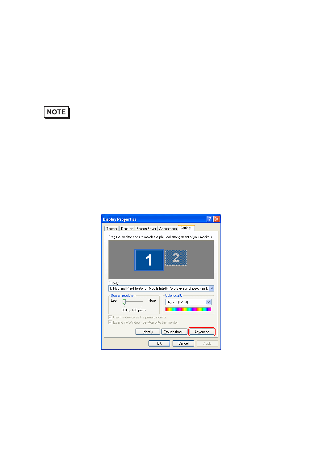
(1) Open [Control Panel] from the Start menu.
(2) Open [Display]. (In Windows XP, this is in the [Appearance and Themes] category.)
(3) In the Settings tab, click [Advanced].
9
Page 11
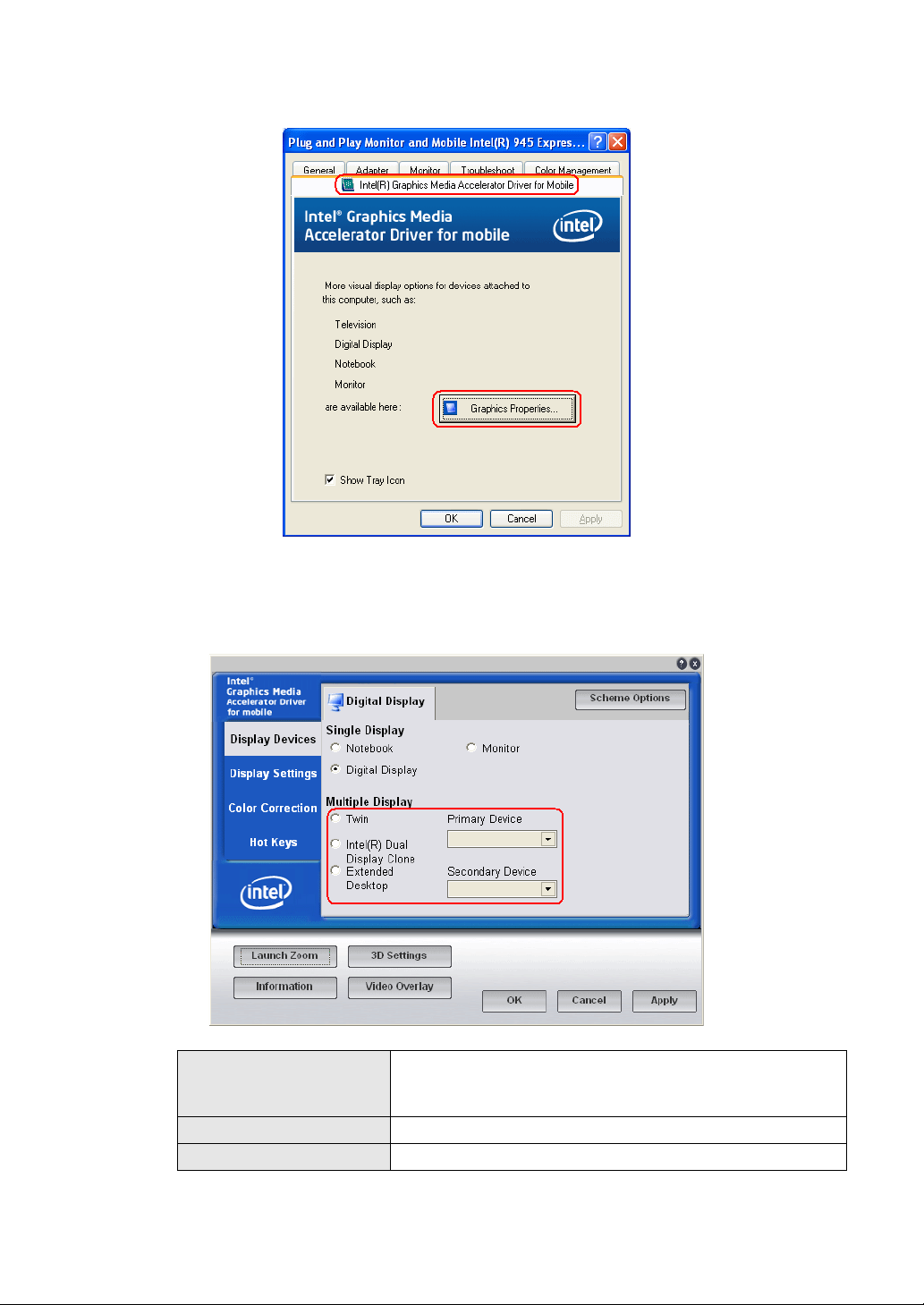
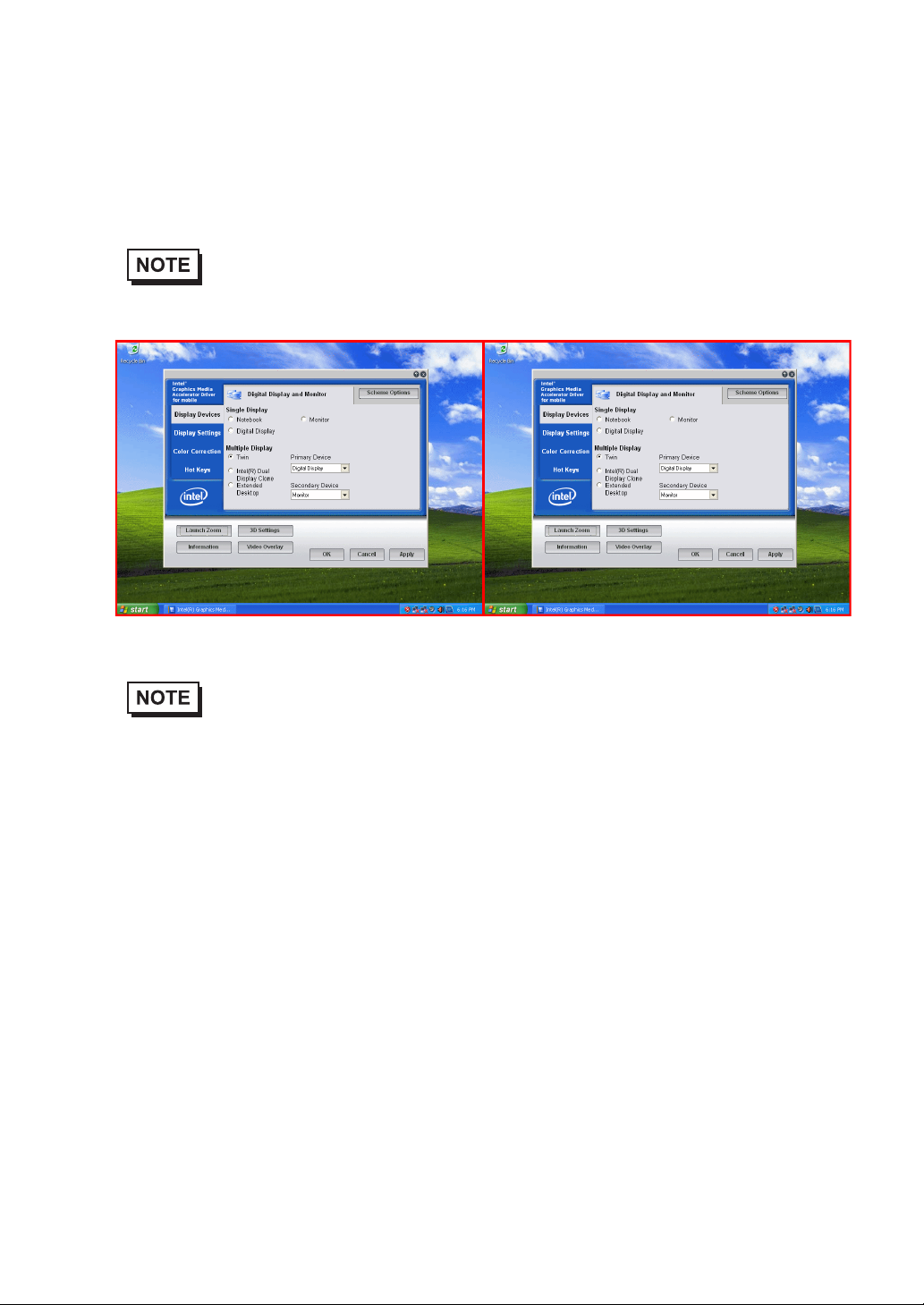
(4) In the Intel(R) Graphics Media Accelerator Drive for Mobile tab, click [Graphics Properties].
(5) In the properties window that appears, select the menu to display using [Multi-display]
monitor for the primary device and the extended monitor for the secondary device.
* For details about each menu, refer to “ Multi-display function types (page 11)”.
Select this option when using the PL3000 Series TFT type.
[Notebook]
[PC monitor] This is the monitor connected with an analog RGB cable.
[Digital display] This is the monitor connected with a DVI cable.
Do not select this option when using the PL3000 Series box
type as the image signal output will stop.
*
. Select the main
10
(6) Click [Apply].
Page 12
Multi-display function types
Twin
This allows the same information to be displayed on two monitors.
®
Intel
Dual Display Clone
• Like the Twin type, this allows the same information to be displayed on two monitors, however,
display may differ according to the selected resolution.
Primary Device Secondary Device
• When using the TFT type or keypad type of the PL3000 series, if you use the Digital FP as a
dual clone monitor, use an RGB cable to connect the PL u nit and the monitor. The TFT type and
keypad type of the PL series can output only RGB signals. To perform touch control on the
screen while dual clone display is active, use an RS232C cable to connect the PL unit and the
monitor, as well. Establishing a connection using an RS232C cable enables touch control on the
screen.
• When using the PL3000 series, if you are using a Digital FP with front USB terminal as a dual
clone/twin display monitor, you must use a USB cable, an RGB and an RS232C cable to connect
the PL unit and monitor.
11
Page 13

Extended desktop
You can divide one desktop to be displayed on two monitors.
Primary Device Secondary Device
• When using the TFT type or keypad type of the PL3000 series, if you use the Digital FP as a
monitor for an extended desktop, use an RGB cable to connect the PL unit and the monitor. The
TFT type and keypad type of the PL series can output only RGB signals. Touch control on the
screen cannot be performed while using the extended desktop function.
12
Page 14

1 Setting Up
Software
1. Software Configuration
2. Setting Up an HDD with no Pre-installed OS
3. Setting Up an HDD with Pre-installed OS
4. PL Dedicated Software
This chapter describes the setting procedures for the PL dedicated programs and the setting parameters.
1-1
Page 15

PL3000 Series Reference Manual
1.1 Software Configuration
If you purchased a PL unit with the OS pre-installed, the software has been pre-installed.
If you purchased a PL unit without the OS pre-installed, you can download each software program from the
Pro-face support site “Otasuke Pro!”.
SEE
1.2.2 Setting Up the PL Dedicated Software (page1-3)
1.2 Setting Up an HDD with no Pre-installed OS
First, when you use a PL with no pre-installed OS, you will need to install either Windows®2000 or
Windows®XP. You also need to install any required utility software.
1.2.1 Setting Up the OS
Install your operating system. For the setup procedures about the OS, refer to that product’s installation manual.
• Specify [Disabled] for the USB2.0 Controller of the BIOS when you install
®
commercial Windows
SEE
• The PL unit supports Windows
Pack 2. The PL unit performance cannot be guaranteed when any other operating
system is used. Download the Intel
the Digital support site.
• Installing the OS with [AHCI Configuration] set to [Enable] requires Intel
Storage Manager. Download the Intel
USB Controller Configuration (page2-23)
2000, using a USB CD/DVD-ROM drive.
®
2000 Service Pack 4 and Windows®XP Service
®
Matrix Storage Manager from “Otasuke Pro!,”
®
Matrix Storage Manager from “Otasuke
®
Matrix
1-2
Pro!,” the Digital support site.
SEE
AHCI Configuration (page2-19)
Page 16
1.2.2 Setting Up the PL Dedicated Software
Download the necessary drivers and utility software from the Pro-face support site “Otasuke Pro!”.
URL http://www.pro-face.com/otasuke/
• Do not install the battery driver when a battery unit is not mounted; otherwise, the Battery
Unit Disconnected Error will be displayed. T o recover the error, the battery driver should be
uninstalled.
For procedure to uninstall the battery driver, refer to the following section.
Chapter 1 Setting Up Software
SEE
• The setup requires a USB keyboard.
• For details about the drivers and utility software, refer to the following section.
SEE
5.1 Problems and Countermeasures (page5-2)
1.4 PL Dedicated Software (page1-13)
[Proface] Folder Configuration
The following diagram describes the configuration of this folder. (For all Windows® versions)
[Proface]
[API] API-DLL
[Backlight] Backlight Control Console Application
[KeyClick] Keyboard Emulator
[Shutdown]
[Client] Remote Shutdown Client
[Sysmon] System Monitor/RAS Application
1-3
Page 17

PL3000 Series Reference Manual
• When a LAN or a printer is added, you need to change the Windows® system configuration
using the following procedure.
(1)When the Windows
appears. When your media is DVD-ROM, replace “CD-ROM” with “DVD-ROM”.
Insert the CD labeled “Windows
drive (D:), and click [OK].
When copying the file from other locations such as a floppy disk or network
server, also click the [OK] button.
*1
“xx” is your OS.
Example) When using Windows
(2)Select the folder where you will change the system configuration and click [OK].
Double-click the [I386] folder in the Windows
D:\I386 (When the drive is “D”)
®
system configuration settings are changed, the following message
®
xx*1 Professional CD-ROM” in the CD-ROM
®
XP: “Windows®XP Professional CD-ROM”
®
installation media.
1-4
Page 18

1.3 Setting Up an HDD with Pre-installed OS
In the PL with pre-installed OS, the following software has been installed in advance.
PL with Windows® 2000 Pre-installed
• Windows® 2000 Professional operating system manufactured by Microsoft Corporation
• PL dedicated utility software and drivers manufactured by Pro-face
PL with Windows®XP Pre-installed
• Windows®XP Professional operating system manufactured by Microsoft Corporation
• PL dedicated utility software and drivers manufactured by Pro-face
• Each pre-installed operating system is designed specially for PL3000.
• For details about the drivers and utility software, refer to the following section.
Chapter 1 Setting Up Software
SEE
1.4 PL Dedicated Software (page1-13)
1-5
Page 19
PL3000 Series Reference Manual
[Proface] Folder Configuration
A [Proface] folder is prepared on the C drive. The following diagram describes the configuration of this
folder. (For all Windows
[Proface]
[API] API-DLL
[Backlight] Backlight Control Console Application
[KeyClick] Keyboard Emulator
[Setup] Media Image
[Shutdown]
[Client] Remote Shutdown Client
[SysCfg] System configuration monitoring software
[Sysmon] System Monitor/RAS Application
• When a LAN or a printer is added, you need to change the Windows® system configuration
using the following procedure.
(1)When the Windows
®
versions)
®
system configuration settings are changed, the following message
appears. When your media is DVD-ROM, replace “CD-ROM” with “DVD-ROM”.
Insert the CD labeled “Windows® xx*1 Professional CD-ROM” in the CD-ROM
drive (D:), and click [OK].
When copying the file from other locations such as a floppy disk or network
server, also click the [OK] button.
*1
“xx” is your OS.
Example) When using Windows
®
XP: “Windows®XP Professional CD-ROM”
(2)Select the folder where you will change the system configuration and click [OK].
C:\Proface\Setup\I386
1-6
Page 20
Chapter 1 Setting Up Software
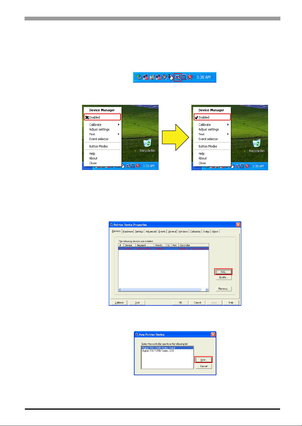
• The UPDD device driver has a driver to connect to USB devices built in by default setting.
UPDD settings are disabled by default setting for the PL3000 series box type. When connecting
the unit to the FP Series, these setting should be enabled.
<Procedure for enabling the setting>
(1)Click the icon shown above.
(2)Change the Enabled check mark from 8 to 9.
UPDD [USB Connection] settings disabled UPDD [USB Connection] settings enabled
It is necessary to install the UPDD Serial driver when using the PL unit with a serial connection.
<Procedure for installing the UPDD Serial driver>
(1)From the [Start] menu, click [Programs], [UPDD], and then [Settings].
(2)Click [Add].
(3)Select [Digital TSC-1310D Series, Serial], and click [Next].
Follow the on-screen instructions to install the driver.
1-7
Page 21
PL3000 Series Reference Manual
1.3.1 Setting Up OS
Set up the Pre-installed OS in the PL unit.
Windows® 2000 Setup Procedure
This section describes the setup procedure for Windows® 2000. The setting parameters vary depending on
your environment. Ask your network administrator for the appropriate parameters.
• When setup is completed, a README file is created on the desktop. The README file contains
details regarding software and information released since the creation of this manual. Read the
README file first after setup is completed.
• The OS setup operation requires a keyboard.
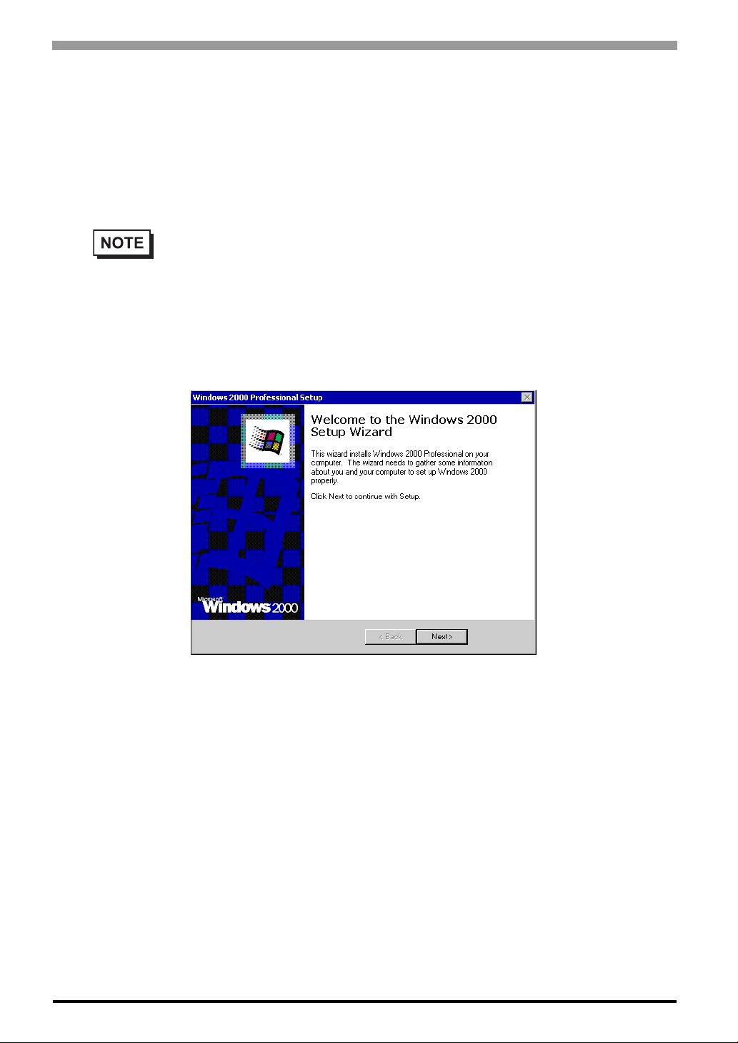
(1) Once the PL unit’s power is turned ON, this HDD unit’ s [W indows 2000 Professional Setup] screen, and
then the [Welcome to the Windows 2000 Setup Wizard] will appear. Click the [Next] button.
1-8
(2) The [License Agreement] screen will appear.
After reading the contracts, press [I accept this agreement] if you agree, and click the [Next] button.
Page 22

(3) The [Regional Settings] screen will appear.
After entering the data for your area, click the [Next] button.
(4) The [Personalize Your Software] screen will appear.
After entering your name [Name] and [Organization], click the [Next] button.
Chapter 1 Setting Up Software
(5) The [Your Product key] screen will appear.
After entering the product key data on the license sticker, click the [Next] button.
(6) The [Computer Name and Administrator Password] screen will appear.
Enter the [Computer Name and Administrator Password], and [Confirm Password], then click the [Next]
button.
When entering the [Computer Name], if the name shown on the display is not correct, you can enter
another name. When the computer is connected to a network, be sure to ask your network manager what
is the correct name for this field.
(7) The [Date and Time Settings] screen will appear.
After entering these settings, click the [Next] button.
1-9
Page 23
PL3000 Series Reference Manual
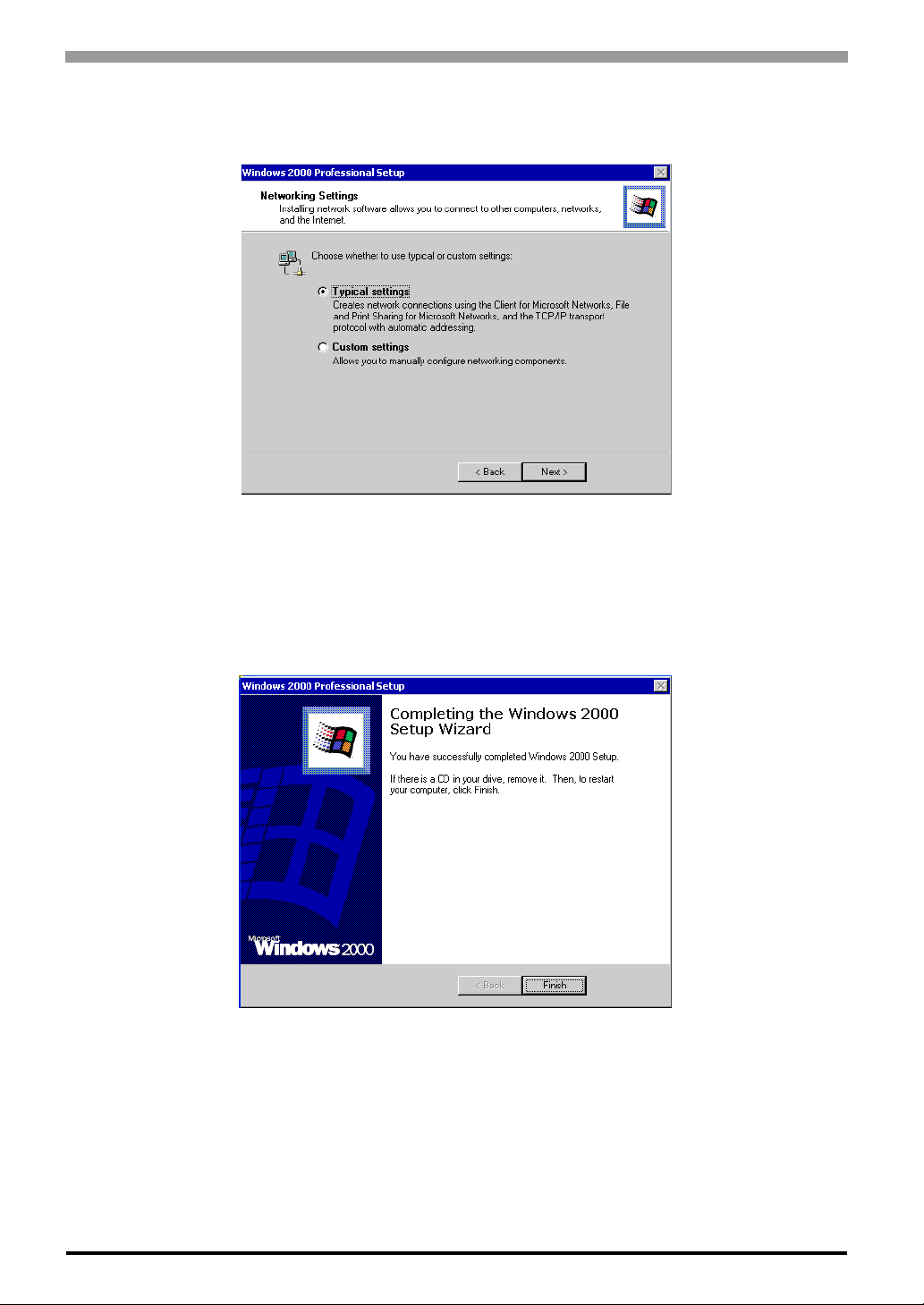
(8) The [Network Settings] screen will appear.
Choose whether to use typical or custom settings depending on your PC circumstantce.
(9) The [Workgroup or Computer Domain] screen will appear.
Choose whether to make your PC on a network or not depending on your PC circumstance.
(10) [Performing Final Tasks] is automatically done by the PL.
The [Completing the Windows 2000 Setup Wizard] will appear . Press the [Finish] b utton and the system
will automatically restart.
(11) When the [Network Identification Wizard] and the [Welcom to the Network Identification Wizard] is
started, please press the [Next] button. The [Users of This Computer] screen will appear. After entering
1-10
the desired settings, press the [Next] button and then press the [Finish] button.
Page 24

Chapter 1 Setting Up Software
Windows® XP Setup Procedure
This section describes the setup procedure for Windows® XP. The setting parameters vary depending on your
environment. Ask your network administrator for the appropriate parameters.
• When setup is completed, a README file is created on the desktop. The README file contains
details regarding software and information released since the creation of this manual. Read the
README file first after setup is completed.
• The OS setup operation requires a keyboard.
®
(1) Once the power of the PL unit with Windows
Microsoft Windows] screen will appear. Click [Next].
XP pre-installed is turned ON, the [Welcome to
(2) The [The End User License Agreement] screen will appear.
After reading the contents, press [Yes, I accept] if you agree, and click [Next] to continue.
(3) The [Help protect your PC] screen will appear.
®
Choose whether to update Windows
protect my PC by turning on Automatic Updates now (recommended)]. T o disable it, check [Not right
now]. Click [Next] to continue.
automatically. To enable the Automatic Updates, check on [Help
1-11
Page 25
PL3000 Series Reference Manual
(4) The [What’s your computer’s name?] screen will appear.
After entering the computer’s name, click [Next] to continue. At default se tting, the computer’s name
has been entered. If it’s not necessary to change it, click [Skip].
(5) The [What’s your Administrator password?] screen will appear.
If the password is set, enter the password in [Administrator password:] and [Confirm password:] and
click [Next]. If the password is not set, click [Skip].
(6) The [Is this computer in a domain?] screen will appear.
To join the domain, select [Yes, make this computer a member of the following domain:] and enter the
domain’s name. Not to join the domain, click [Next] to continue.
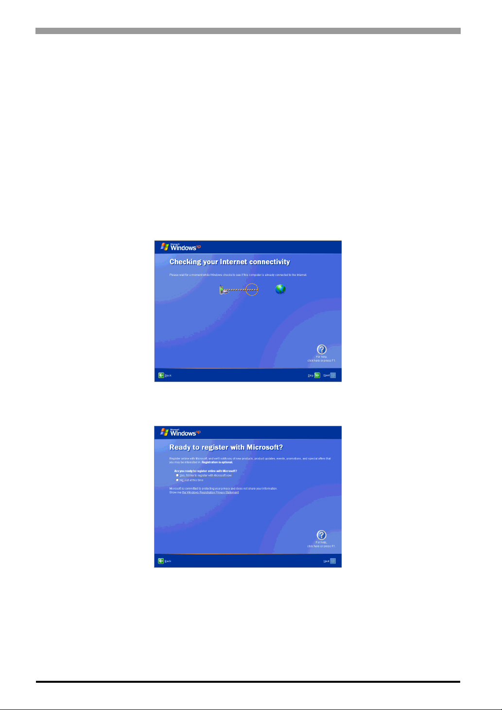
(7) The [Checking your internet connectivity?] screen will appear and your internet connectivity will be
automatically checked.
(8) The [Ready to register with Microsoft?] screen will appear. If you register, check [Yes, I’d like to regis-
ter with Microsoft now]. If not, check [No, not at this time]. Press [Next].
(9) The [Who will use this computer?] will appear. Up to 5 names can be entered for a user’s name. After
entering the user’s name, click [Next] to continue.
(10) The [Thank you!] screen will appear. Click [Finish] to complete the setting.
1-12
Page 26

1.4 PL Dedicated Software
1.4.1 Driver
Six types of dedicated PL drivers (AHCI, Chipset, Audio, Graphic Accelerator, LAN and T ouch Panel Driv er
(Mouse Emulator)) are available.
If you purchased the PL with no pre-installed OS, download the drivers from the Pro-face support site “Otasuke Pro!”. (A PL unit that has been recovered using the Recovery Media will have all the required drivers
installed). The explanation given in this section assumes that the [Proface] folder has been created on drive C.
• Once drivers are installed in the PL unit, they cannot be uninstalled.
• For the installation procedure and cautions, refer to the download page at the Otasuke Pro! site.
URL http://www.pro-face.com/otasuke/
AHCI Driver
AHCI driver made by Intel®.
Chapter 1 Setting Up Software
Installing the driver enables PL with no pre-installed OS to install OS.
Chipset Driver
Chipset driver made by Intel®.
Installing the Chipset driver adds the Chipset feature to the OS.
Double-click on the “Setup.exe” file located in the following folder. Follow the instructions given on the
screen to install the driver.
Audio Driver
High Definition Audio driver made by Realtek.
Installing the Audio driver enables the OS’ Audio feature.
Double-click on the “Setup.exe” file located in the following folder. Follow the instructions given on the
screen to install the driver.
Graphic Accelerator Driver
Display driver made by Intel®.
Installing the Graphic Accelerator Driver will accelerate the screen refresh speed, using special hardware features.
1-13
Page 27

PL3000 Series Reference Manual
LAN Driver
This is a driver for the IntelR Ethernet Controller.
Installing the Ethernet Controller Driver enables LAN1 and LAN2 to be available.
• For instructions on how to start a PL unit over LAN, refer to the following.
SEE
3.7 Restarting/Shutting Down the PL from a Remote Server (page3-27)
Touch Panel Driver (Mouse Emulator)
Install the Touch Panel Driver in the PL unit. It’s necessary to agree to DMC’s Mouse Emulator Software
(TSC-1310D/DD) License in advance.
SEE
Appendices 4 License Agreement (pageA-6)
• You can open “Touch Panel Property” by selecting the [Start] -> [Programs] -> [UPDD] ->
[Settings]. In this dialog box, you can specify the details of the touch panel operation.
• If the touch position recognized in the panel deviates from the actual touch, you need to calibrate
the touch panel. Select the [Start] -> [Programs] -> [UPDD] -> [Calibration]. When a cross
appears on the screen, press it. Then click [OK] in the [Confirmation after calibration] dialog box
to finish the calibration.
1-14
Page 28

1.4.2 Special Application Program Features
The special programs designed for the PL unit are located in the following folders. The file storage locations
given in the table below assume that the [Proface] folder already exists on drive C.
Chapter 1 Setting Up Software
File Name
BlCtrl.exe C:\Proface\Backlight\
BlSaver.scr
BlBright.cpl
Keyclick.exe C:\Proface\Keyclick
Ioctl.dll
Smonras.dll
SmSRvCPL.cpl
Sysmon.sys C:\Windows\System32\Drivers C:\Winnt\System32\Drivers
SystemMonitor.exe C:\Proface\Sysmon\GUI
C:\Windows\System32 C:\Winnt\System32
C:\Windows\System32 C:\Winnt\System32
Windows
®
XP Windows®2000
Backlight Control Console Application: BlCtrl.exe
This command line utility is used to turn OFF both the PL backlight and display. This program runs on the
command prompt.
Settings Used BlCtrl.exe [ON/OFF]
Option Switch ON: Displayed / OFF: Not Displayed
Return Value 0: Completed Normally / -1: Option Switch Error
• If your application requires that the OS continuously turn the backlight display ON
and OFF, be sure to use the RAS Features dll, Ioctl.dll.
• Not available with the box type of the PL3000 series.
Backlight OFF Screen Saver: BlSaver.scr
This software is used to turn OFF the PL backlight after a specified period of inactivity. The use of this feature
will help to extend the life of the PL backlight. This program runs on Windows®.
• Certain application programs may not allow the PL backlight to turn OFF. Test each program
individually to check if the screen saver will operate correctly before use.
• Not available with the box type of the PL3000 series.
1-15
Page 29

PL3000 Series Reference Manual
Backlight Brightness Adjustment: BlBright.cpl
Backlight brightness can be set to one of four levels: Level 0, Level 1, Level 2 or Level 3.
Brightness level 0: Very dark
Brightness level 1: Somewhat dark
Brightness level 2: Somewhat bright
Brightness level 3: Very bright
To use this program when you use Windows
Panel], when using Windows®XP click the [Backlight Brightness] icon of the [Control Panel]’ s [Appearance
and Themes]. The default setting is Brightness level 3.
Keyboard Emulator: Keyclick.exe
This program allows the User’s mouse operation to perform keyboard-like data input. When this program is
®
executed on Windows
This is a software keyboard provided by IN-flNITY soft (KeyClick32). Be sure to read the license agreement
in the Appendix before use.
, a keyboard is displayed on the screen of the PL unit.
®
2000, click the [Backlight Brightness] icon of the [Control
SEE
Appendices 4 License Agreement (pageA-6)
• Certain application programs may not support this keyboard emulator. Test each application
individually to check if the keyboard emulator will operate correctly.
®
• This program cannot be used to enter Windows
information.
• To change the Keyclick program’s font size a keyboard is required.
startup screen User Name and Password
API-DLL
These dynamic link libraries allow users to access RAS features that operates on the PL via custom-made
applications. The following two types are available.
For details, refer to the API Reference Manual which can be downloaded from the Pro-face support site “Otasuke Pro!”
RAS Features: Ioctl.dll
This dynamic link library allows users to access RAS features that operates on the PL via custom-made PL
applications.
Shared Memory Access: Smonras.dll
(URL http://www.pro-face.com/otasuke/).
1-16
This dynamic link library allows users to access shared memory via remote RAS features.
Page 30

Chapter 1 Setting Up Software
System Monitor Property: SmSRvCPL.cpl
This program allows the user to set the notification method used in event of an error/alert while the RAS feature monitors the system.
System File: Sysmon.sys
This system file allows use of the RAS and System Monitoring features. This file sho uld not be modified. If it
is modified, the RAS and System Monitoring features may not operate correctly.
System Monitoring/RAS Application: SystemMonitor.exe
The RAS and System Monitoring features allow users to monitor temperature, voltage, and fan operation
errors/alerts. This program is started automatically at the same time as the OS.
System Monitoring Program: SystemMonitor.exe
SEE
Watchdog Parameter Setup Program: System Monitor Property
SEE
3.3.3 When an Error Occurs (page3-14)
3.3.4 When an Alert Occurs (page3-15)
3.3.1 Description (page3-11)
1-17
Page 31

PL3000 Series Reference Manual
1-18
Page 32

2 System Setup
1. System Setup Screen Operation
2. System Parameters Setting
This chapter describes how to operate the system setup screen and how to set system parameters.
2-1
Page 33

PL3000 Series Reference Manual
2.1 System Setup Screen Operation
This section describes the operation of the BIOS setup screen.
• Normally, use only the factory (default) settings.
(1) Connect a USB keyboard to the PL.
(2) Turn the PL’s power ON.
(3) After the boot-up screen comes up, press the [F2] key . The setup utility starts and the following screen
appears.
Menu
2-2
KEYBOARD ACTION KEYS
Provides a summary of the keyboard keys used to carry out the set-up.
Press the [F1] key to display the help for the system setup.
Press the [F9] key to reset all settings to the default settings.
Press the [F10] key to save the settings and exit the system setup menu.
SYSTEM SETTING SELECTION AREA
Each of the titles (areas) listed here contains system setting items.
(4) To use the [ ← ] [ → ] arrow keys, change the menu contents. A setting screen of each system will be
displayed.
(5) To use the [ ↑ ] [ ↓ ] arrow keys, move up and down the cursor to select an item of the system, then con-
firm it by the [Enter] key.
(6) Change the value of the confirmed item with the [-] and [+] keys.
(7) To return from the sub layer to the main layer, press the [Esc] key.
Help area
Shows the information of
the items you selected.
Page 34

BIOS Setup Screen Configuration
Chapter 2 System Setup
MAIN
)
2-4 page
Specify the drive/date.
Advanced
)
2-7 page
Set the system details.
IDE Channel/SATA Port
)
2-5 page
Display the information for the
connected devices.
Processor Configuration
)
2-10 page
Set the CPU.
Power-ON Configuration
)
2-12 page
Set the PL operations at
power-on.
Video (Intel IGD)
Configuration
)
2-14 page
Set the graphics details.
Cache Memory
)
Set the cache memory-related
Integrated Device
Set the integrated devices.
DMI Even Logging
Set the DMI event logging
Soft Mirror Status
Display the soft mirror status.
2-16 page
items.
Configuration
)
2-18 page
)
2-25 page
options.
)
2-26 page
CPU Thermal Configuration
)
Set the CPU temperature
monitoring feature.
I/O Device Configuration
Set the I/O address/interrupt
PCI Configuration
Set the USB controller.
2-11 page
)
2-20 page
No.
)
2-21 page
Set PCI.
USB Controller
Configuration
)
2-23 page
Security
)
2-27 page
Set the password/security
options.
Boot
)
Specify the boot order of
Exit the BIOS screen.
2-28 page
devices.
Exit
)
2-29 page
2-3
Page 35

PL3000 Series Reference Manual
2.2 System Parameters Setting
Select the items to set up the system information. Here, we introduce the system parameters of each item.
• Normally, use only the factory (default) settings.
• An item in [ ] indicates the factory default setting.
2.2.1 Main
System Time
Shows the time which the PL currently recognizes. Move the cursor by the [Tab]key and set a proper time for
the PL by the [Tab], [+] and [-] keys because the factory default setting is the Japan’s Standard Time
(GMT+09:00).
System Date
Shows the date which the PL currently recognizes. Set a proper date for the PL by the [+] and [-] keys.
IDE Master Channel 0 Master /
IDE Slave Channel 0 Slave /
IDE Channel 1 Master /
IDE Channel 1 Slave /
SATA Port 0 /
SATA Port 1
Displays the name of devices connected to the PL. Pressing the [Enter] key will call up the Parameter settings
menu.
SEE
2-4
IDE Channel / SATA Port (page2-5)
Page 36

Chapter 2 System Setup
System Memory
Shows the capacity of the “System Memory”.
Extended Memory
Shows the capacity of the “Extended Memory”. It is the loaded memory - the size of the Video Memory.
IDE Channel / SATA Port
Point out the cursor at the [IDE Channel 0 Master], [IDE Channel 0 Slave], [IDE Channel 1 Master], [IDE
Channel 1 Slave], [SATA Port 0], [SATA Port 1] on the “Main screen”, and then press the [Enter] key, so
that the following screen is shown.
Type
Specifies a type of drive which you use.
[Auto] Automatically specifies whether to connect to the drives and the type of drive
that you use.
[None] Specifies that all the drives are not used.
[ATAPI Removable] Connects the ATAPI removable drive.
[CD-ROM] Connects the CD-ROM driv e.
[IDE Removable] Connects the IDE removable drive.
[Other ATAPI] Connects other ATAPI devices.
[User] You can directly specify the number of cylinders, heads and sectors.
•Select [Auto] to have the PL recognize the hardwar e properly.
2-5
Page 37

PL3000 Series Reference Manual
Multi Sector Transfers
Specifies the number of sectors per block, which are transferred to the memory. When [Type] is [None] or
[Auto], the selection is disabled.
[Disabled] Transfers by sector.
[2 Sectors] Transfers 2 sectors at a time.
[4 Sectors] Transfers 4 sectors at a time.
[8 Sectors] Transfers 8 sectors at a time.
[16 Sectors] Transfers 16 sectors at a time.
LBA Mode Control
Enables or disables the Logical Block Address (LBA) instead of the Cylinders, Headers, and Sectors. When
[Ty pe] is [No ne] or [Auto], the selection is disabled.
[Disabled] Does not use LBA mode.
[Enabled] Uses LBA mode.
32 Bit I/O
Specifies an enabled/disabled state for the 32 bit transferring between CPU and IDE controller.
When the [Type] is [None], nothing is displayed.
[Enabled] Uses 32 bit transfer.
[Disabled] Does not use 32 bit transfer.
Transfer Mode
Specifies a method of transferring data. When the [type] is [None], nothing is displayed. When [Type] is
[None] or [Auto], the selection is disabled.
[Standard] Specifies Transfer Mode to PIO Mode 0.
[Fast PIO 0 to Fast PIO 4] Specifies Transfer Mode to Fast PIO Mode 1 - Mode 4.
[FPIO 3/DMA 1] Uses Fast PIO Mode 3 or DMA Mode 1.
[FPIO 4/DMA 2] Uses Fast PIO Mode 4 or DMA Mode 2.
Ultra DMA Mode
Specifies a Ultra DMA mode for the Hard drive. When [Type] is [None] or [Auto], the selection is disabled.
[Disabled] Does not use Ultra DMA mode.
[Mode 0 to Mode 5] Specifies the Ultra DMA mode.
2-6
Page 38

2.2.2 Advanced
Chapter 2 System Setup
Processor Configuration
Point the cursor to [Advanced Processor Configuration] and press the [Enter] Key to go to the CPU set-up screen.
SEE
Power-ON Configuration
Point the cursor to [Power-ON Configuration] and press the [Enter] Key to go to the set-up screen for the PL
operations at power-on.
SEE
Video (Intel IGD) Configuration
Point the cursor to [Video (Intel IGD) Configuration] and press the [Enter] Key to go to the display set-up screen.
SEE
Cache Memory Configuration
Point the cursor to the [Cache Memory] and press the [Enter] Key, so that you can go to the set-up screen for
Cache Memory.
SEE
Integrated Device Configuration
Point the cursor to [Integrated Device Configuration] and press the [Enter] Key to go to the integrated device
Processor Configuration (page2-10)
Power-ON Configuration (page2-12)
Vi deo (Intel IGD) Configuration (page2-14)
Cache Memory Configuration (page2-16)
set-up screen.
SEE
Integrated Device Configuration (page2-18)
2-7
Page 39

PL3000 Series Reference Manual
DMI Event Logging
Point the cursor to [DMI Event Logging] and press the [Enter] Key to go to the DMI event logging set-up
screen.
SEE
Soft Mirror Status
Point the cursor to [Soft Mirror Status] and press the [Enter] Key to go to the display screen fo r the soft mirror
status.
SEE
Installed O/S
Specifies a type of OS of the unit.
[Other] Set when using a non-Plug and Play OS.
[Win2K/XP] Set when using a Plug and Play OS.
Reset Configuration Data
Specifies whether you want to reset the Plug & Play information which is recorded in the Extended System
Configuration Data (ESCD) Block of the CMOS RAM, when the system boots up next time.
[Yes] Initializes data the next time the system boots up.
[No] Does not initialize data.
Even when [Yes] is selected, the selection automatically returns to [No] after the data is initialized.
Large Disk Access Mode
Specifies the access mode. When you use UNIX or NetWare for OS, the setting should be [Other].
DMI Event Logging (page2-25)
Soft Mirror Status (page2-26)
Automatically reset to [No] after the data is initialized.
[Dos] Use this setting normally.
[Other] Use this setting when using Linux, UNIX, or a similar OS.
Local Bus IDE adapter
Specifies whether to use the IDE adapter .
[Enabled] Uses the Local Bus IDE adapter.
[Disabled] Does not use the Local Bus IDE adapter.
RAS Reset Port Mask
Specifies whether to enable or disable the RAS Reset Port feature.
[Enabled] Enables the Mask feature, and disables the RAS Reset Port feature.
[Disabed] Disables the Mask feature, and enables the RAS Reset Port feature.
Show CMOS Error
Specifies whether to display the CMOS Checksum Error message when the error occurs.
[Enabled] Shows error message.
[Disabled] Does not show error message.
The error messages that can be shown/hidden in this setting are as follows:
CMOS Checksum Error
CMOS Battery Failure
2-8
Page 40

Chapter 2 System Setup
CMOS Time Not Set
Summary Screen
Specifies whether the configuration information of the running system (Summary Screen) is displayed.
[Enabled] Shows the Summary Screen.
[Disabled] Does not show the Summary Screen.
Enable Memory gap
Specifies an enabled/disabled state for the Memory gap.
[Enabled] Reserves a memory gap for an expansion card.
[Disabled] Use this setting normally.
Extended Memory Testing
Specifies whether a test for the Extended Memory needs to be executed at the system starting-up. The test
types are listed below.
[Normal] Normal test
[Just Zero it] Simple test
[None] No test
2-9
Page 41

PL3000 Series Reference Manual
Processor Configuration
Specifies the settings for the CPU. Point the cursor to [Processor Configuration] on the [Advanced] screen
and press the [Enter] Key to display the following screen.
CPU Thermal Configuration
Point the cursor to [CPU Thermal Configuration] and press the [Enter] Key to go to the set-up screen for CPU
temperature monitoring.
Core Multi-Processing
Specifies whether to distribute processing using multiple processor cores.
[Enabled] Distributes processing.
[Disabled] Does not distribute processing. Operates as a single core.
No Execute Mode Mem Protection
Specifies whether to use the data execution prevention feature.
[Enabled] Uses the data execution prevention feature.
[Disabled] Does not use the data execution prevention feature.
Intel(R) Virtualization Technology
Specifies whether to run multiple OSs simultaneously on the PL unit.
[Enabled] Uses multiple OSs simultaneously.
[Disabled] Does not use multiple OSs simultaneously.
Set Max Ext CPUID = 3
Specifies the maximum value of the CPUID basic information which can be recognized with the CPUID
instruction.
[Enabled]
[Disabled] The maximum value is set to the allowable maximum value of the CPU.
The maximum value is fixed to “3”. Select this option when you use an OS which
does not support more than “3” pieces of extended CPUID basic information.
2-10
Page 42

Chapter 2 System Setup
CPU Thermal Configuration
Specifies the settings for the CPU temperature monitoring. Point the cursor to [CPU Thermal Configuration]
on the [Advanced Processor Configuration] screen and press the [Enter] Key to display the following screen.
Thermal Control Circuit
Specifies whether to use the CPU temperature protection feature.
[Disabled] The CPU temperature protection feature is not used.
[TM1] The CPU is operated at 50% duty ratio.
PROCHOT# Enable
Specifies whether to issue a “PROCHOT#” signal when the CPU’s temperature reaches the maximum safe
operating temperature.
[Enabled] Issues a “PROCHOT#” signal when the maximu m safe operating temperature
is reached.
[Disabled] Does not issue a “PROCHOT#” signal when the maximum safe operating
temperature is reached.
2-11
Page 43

PL3000 Series Reference Manual
Power-ON Configuration
Specifies the PL operations at power-on. Point the cursor to [Power-ON Configuration] on the [Advanced]
menu and press the [Enter] Key to display the following screen.
Power On Delay
Specify whether to set standby time before the system starts up.
[Enabled] The system waits for 4 seconds before start-up.
[Disabled] The system starts up normally.
• If a USB device such as USB memory is connected to the PL when the PL is started, the following phenomenon may occur, depending on the device:
• It takes about 1 minute before the OS starts up.
• The PL does not recognize the USB device.
These problems may be solved by setting [Power On Delay] to [Enable].
Restore Main Power
Specifies the operation when the main power is turned to ON. When [Power on Delay] is [Enabled], this
option is not displayed.
[Stay Off] The PL unit does not start when the reset switch is turned to ON.
It starts when the reset switch is pressed.
[Power On] The PL unit starts when the main power is turned to ON.
• Normally, specify [Power On] for use.
• When you change the setting to [Stay off], launch the OS again without turning the main power
OFF.
2-12
Page 44

Power On Beep
Specify whether to sound a “beep” upon system boot-up.
[Enabled] Sounds at start-up.
[Disabled] Does not sound at start-up.
Chapter 2 System Setup
2-13
Page 45

PL3000 Series Reference Manual
Video (Intel IGD) Configuration
Specifies graphic-related settings. Point the cursor to [Video (Intel IGD) Configuration] on the [Advanced]
screen and press the [Enter] Key to display the following screen.
• When using the PCI graphic board, make sure to set the IGD#0 setting to
[Disabled].
• The PCI graphic board can be used only with the PL3000 series box type.
IGD #0
Shows an enabled/disabled state for graphics device 0 in the chipset.
[Disabled] Shows that the embedded graphics device cannot be used.
[Auto] Shows that the embedded graphics device can be used.
• When you are using the PL3000 series box type, another graphic device embedded in the
chipset, which is not displayed above, can be enabled or disabled. Select either [Disabled] or
[Auto].
IGD #1
Specifies whether to enable or disable the graphics device 1 in the chipset.
When the IGD #0 is [Disabled], this option is not displayed.
[Disabled] Does not use the embedded graphics device.
[Auto] Uses the embedded graphics device.
2-14
Page 46

Chapter 2 System Setup
DVMT 3.0 Mode
Specifies the form of the memory used by the graphic in the chipset.
When the IGD #0 is [Disabled], this option is not displayed.
[Fixed] The fixed area is used as video memory.
[DVMT] The DVMT (Dynamic Video Memory Technology) feature is used so that
video memory is dynamically allocated from main memory.
[Combo] Combination of [Fixed] and [DVMT].
Pre-Allocated Memory Size
Specifies the video memory size which BIOS allocates in advance as a fixed area at start-up.
When the IGD #0 is [Disabled], this option is not displayed.
[1MB] Allocates 1 MB as video memory.
[8MB] Allocates 8 MB as video memory.
Total Graphics Memory
Specifies the total memory size allocated to video memory. When [DVMT 3.0 Mode] is set to [Fixed] or
[Combo], the fixed value is displayed and cannot be changed.
When the IGD #0 is [Disabled], this option is not displayed.
[64MB] Allocates 64 MB as video memory.
[128MB] Allocates 128 MB as video memory.
[MaxDVMT] (224MB) Allocates 224 MB as video memory.
Fixed Graphics Memory
Specifies the size of the video memory used as a fixed area.
When the IGD #0 is [Disabled], this option is not displayed. Also, when [DVMT 3.0 Mode] is either [Fixed]
or [DVMT], this option is not displayed.
DVMT Graphics Memory
Displays the size of the video memory which can be dynamically allocated by using the DVMT feature.
When the IGD #0 is [Disabled], this option is not displayed.
2-15
Page 47

PL3000 Series Reference Manual
Cache Memory Configuration
Specifies the parameters for the cache memory. Point the cursor to the [Cache Memory] on the [Advanced]
screen and press the [Enter] Key, so that the following screen will be displayed.
Memory Cache
Specifies an enabled/disabled state for the Memory Cache.
[Enabled] Uses cache mem o ry.
[Disabled] Does not use cache memory.
Cache System BIOS area
Specifies the cache set-up for the System BIOS area.
[uncached] Does not cache the System BIOS area.
[Write Protect] Write protects the System BIOS area.
Cache Video BIOS area
Specifies the cache set-up for the VIDEO BIOS area.
[uncached] Does not cache the System BIOS area.
[Write Protect] Write protects the System BIOS area.
Cache Base 0-512k
Specifies the cache set-up for the Base Memory, 0 ~ 512k.
[uncached] Does not cache the System BIOS area.
[Write Through] Uses Write Through method.
[Write Protect] Write protects the System BIOS area.
[Write Back] Uses Write Back method.
2-16
Page 48

Cache Base 512-640k
Specifies the cache set-up for the Base Memory, 512 ~ 620k.
[uncached] Does not cache the System BIOS area.
[Write Through] Uses Write Through method.
[Write Protect] Write protects the System BIOS area.
[Write Back] Uses Write Back method.
Cache Extended Memory Area
Specifies the cache set-up for the Extended Memory area.
[uncached] Does not cache the System BIOS area.
[Write Through] Uses Write Through method.
[Write Protect] Write protects the System BIOS area.
[Write Back] Uses Write Back method.
Cache xxxx-xxxx
Specifies the cache setting for each address.
[uncached] Does not cache the System BIOS area.
[USWC Caching] Uses USWC (Uncached Speculative Write Combining) method.
(Only addresses A000-AFFF and B000-BFFF are available.)
[Write Through] Uses Write Through method.
[Write Protect] Write protects the System BIOS area.
[Write Back] Uses Write Back method.
The factory default setting is as follows.
Chapter 2 System Setup
A000 - AFFF Disabled
B000 - BFFF Disabled
C800 - CBFF Write Protect
CC00 - CFFF Write Protect
D000 - D3FF Disabled
D400 - D7FF Disabled
D800 - DBFF Disabled
DC00 - DFFF Disabled
E000 - E3FF Disabled
E400 - E7FF Write Protect
E800 - EBFF Write Protect
EC00 - EFFF Write Protect
2-17
Page 49

PL3000 Series Reference Manual
Integrated Device Configuration
Specifies the settings for the integrated devices. Point the cursor to [Integrated Device Configuration] on the
[Advanced] screen and press the [Enter] Key to display the following screen.
I/O Device Configuration
Point the cursor to [I/O Device Configuration] and press the [Enter] Key to go to the set-up screen for the I/O
addresses and interrupt Nos. of the integrated devices.
SEE
PCI Configuration
Point the cursor to [PCI Configuration] and press the [Enter] Key to go to the PCI resource set-up screen.
SEE
USB Controller Configuration
Point the cursor to [USB Configuration] and press the [Enter] Key to go to the USB controller set-up screen.
SEE
SATA Operational Mode
Specifies the operation mode of the SATA controller.
[Compatible] Legacy mode is used.
[Enhanced] Native mode is used.
I/O Device Configuration (page2-20)
PCI Configuration (page2-21)
USB Controller Configuration (page2-23)
2-18
Page 50

Chapter 2 System Setup
AHCI Configuration
Specifies whether to use the AHCI mode for SATA. When [SATA Operational Mode] is [Compatible], this
option is not displayed.
[Enabled] Uses AHCI mode.
[Disabled] Does not use AHCI mode.
• When installing the OS with [AHCI Configuration] set to [Enable], download Intel
Matrix Storage Manager from the Pro-face support site “Otasuke Pro!”. For the
detailed installation procedure, refer to the “Otasuke Pro!” site.
http://www.pro-face.com/otasuke/
ComINIT OOB-sequence issue
Specifies whether to use an Intel BIOS Spec. 2.0. When [SATA Operation Mode] is [Compatible], or when
[AHCI Configuration] is [Disabled], this option is not displayed.
[Enabled] Uses Intel BIOS Spec. 2.0.
[Disabled] Does not use Intel BIOS Spec. 2.0.
• In AHCI mode, be sure to use an Intel-manufactured AHCI driver. When installing Windows
Vista (not supported OS) on the SATA drive (in AHCI mode) on user authority, using a
Microsoft-manufactured AHCI driver (which is included in the Vista Installer) causes the PL to
hang up during the OS start-up process for installing.
If you use a Microsoft-manufactured AHCI driver accidentally , ch ange this setting to [Disabled]
to install an Intel-manufactured AHCI driver, and then reset the setting to [Enabled].
LAN Controller 1
Displays the enabled/disabled status of the LAN controller 1.
[Enabled] Indicates that LAN controller 1 is enabled.
[Disabled] Indicates tha t L AN controller 1 is disabled.
LAN Controller 2
Specifies whether to use the LAN controller 2.
[Enabled] Uses the LAN controller 2.
[Disabled] Does not use the LAN controller 2.
High-Definition Audio (Azalia)
Specifies whether to use the HD audio feature.
[Auto] Uses the HD audio feature.
[Disabled] Does not use the HD audio feature.
2-19
Page 51

PL3000 Series Reference Manual
I/O Device Configuration
Specifies the address and interrupt level of the I/O ports. Point the cursor to the [I/O Device Configuration] on
the [Integrated Device Configration] screen and press the [Enter] Key, so that the following screen will be
displayed.
COM Port 1, 2, 3, 4
Specifies whether to use the COM port.
[Enabled] Uses the COM port.
[Disabled] Does not use the COM port.
Base I/O Address
Specifies the base I/O address of the COM port. The base I/O address must be unique among the COM ports.
When [COM Port] is [Disabled], this option is not displayed.
[3F8] (Factory default setting for COM1) The base I/O address is set to 03F8h-03FF.
[2F8] (Factory default setting for COM2) The base I/O address is set to 02F8h-02FF.
[3E8] (Factory default setting for COM3) The base I/O address is set to 03E8h-03EF.
[2E8] (Factory default setting for COM4) The base I/O address is set to 02E8h-02EF.
Interrupt
Specifies the interrupt No. of the COM port. The interrupt No. must be unique among the COM ports. When
[COM Port] is [Disabled], this option is not displayed.
[IRQ3] (Factory default setting for COM2) The interrupt No. is set to 3.
[IRQ4] (Factory default setting for COM1) The interrupt No. is set to 4.
[IRQ10] (Factory default setting for COM4) The interrupt No. is set to 10.
[IRQ11] (Factory default setting for COM3) The interrupt No. is set to 11.
2-20
Page 52

Chapter 2 System Setup
PCI Configuration
Specifies the PCI IRQ parameters. Point the cursor to the [PCI Configuration] on the [Integrated Device
Configration] screen and press the [Enter] Key, so that the following screen will be displayed.
PCI/PNP ISA IRQ Resource Exclusion
Point the cursor to [PCI/PNP ISA IRQ Resource Exclusion] and press the [Enter] Key to go to the PCI/PNP
ISA IRQ screen.
PCI IRQ line 1 to PCI IRQ line 8
Specifies the interrupt No. of the PCI.
[Disabled] The PCI is not used.
[Auto Select] The interrupt No. is allocated automatically.
[3] to [15] Each preset interrupt No. is used.
2-21
Page 53

PL3000 Series Reference Manual
PCI/PNP ISA IRQ Resource Exclusion
Specifies the IRQ resource to be reserved for the ISA interrupt.
Point the cursor to [PCI/PNP ISA IRQ Resource Exclusion] on the [PCI Configuration] screen and press the
[Enter] Key to display the following screen.
IRQ3, 4, 5, 7, 10, 11, 15
[Available] IRQ is not reserved.
[Reserve] IRQ is reserved.
2-22
Page 54

Chapter 2 System Setup
USB Controller Configuration
Specifies the USB controller options. Point the cursor to [USB Controller Configuration] on the [Integrated
Device Configuration] screen and press the [Enter] Key to display the following screen.
USB Controller #0
Displays the enabled/disabled status of the USB controller #0.
[Enabled] USB controller #0 is enabled.
[Disabled] USB controller #0 is disabled.
USB Controller #1
Specifies whether to use the USB controller 1.
When [USB Controller #0] is [Disabled], this option is fixed to [Disabled] and not displayed.
[Enabled] Uses the USB controller #1.
[Disabled] Does not use the USB controller #1.
USB Controller #2
Specifies whether to use the USB controller 2.
When [USB Controller #0] or [USB Controller #1] is [Disabled], this option is fixed to [Disabled] and not
displayed.
[Enabled] Uses the USB controller #2.
[Disabled] Does not use the USB controller #2.
2-23
Page 55

PL3000 Series Reference Manual
USB Controller #3
Specifies whether to use the USB controller 3.
When [USB Controller #0], [USB Controller #1] or [USB Controller #2] is [Disabled], this option is fixed to
[Disabled] and not displayed.
[Enabled] Uses the USB controller #3.
[Disabled] Does not use the USB controller #3.
USB 2.0 Controller
Specifies whether to use the USB 2.0 controller.
When [USB Controller #0] is [Disabled], this option is fixed to [Disabled] and not displayed.
[Enabled] Uses the USB 2.0 controller.
[Disabled] Does not use the USB 2.0 controller.
• When installing Windows® 2000 using a USB CD-ROM drive compatible with USB 2.0,
leaving this setting on [Enabled] causes the installation to fai l with a blue screen error. This
occurs because Windows
successfully, change the setting to [Disabled].
®
2000 Installer does not support USB 2.0. T o complete this installation
2-24
Page 56

Chapter 2 System Setup
DMI Event Logging
Specifies the parameters related to DMI event logging. Point the cursor to the [DMI Event Logging] on the
[Advanced] screen and press the [Enter] Key, so that the following screen will be displayed.
Event log validity
Shows the status of the event log storage area.
[Valid] The status is normal.
[Not valid] The status is abnormal.
Event log capacity
Shows the status of the area to which event logs are written.
[Full] The area is full.
[Space Available] The area is not full.
View DMI event log
Point the cursor to [View DMI event log] and press the [Enter] Key to view the DMI event logs.
Event Logging
Specifies whether event logs need to be recorded.
[Enabled] Records event logs.
[Disabled] Does not record event logs.
ECC Event Logging
Specifies whether the event logs related to memory ECC need to be recorded.
[Enabled] Records ECC error related event logs.
[Disabled] Does not record ECC error related event logs.
Mark DMI events as read
Point the cursor to [Mark DMI events as read] and press the [Enter] Key to mark unread event logs as read.
2-25
Page 57

PL3000 Series Reference Manual
Clear all DMI event logs
Specifies whether all the recorded DMI event logs need to be deleted.
[No] Does not delete event logs.
[Yes] Deletes event logs.
Soft Mirror St atus
Displays and specifies the soft mirror status. Point the cursor to the [Soft Mirror Status] on the [Advanced]
screen and press the [Enter] Key to display the following screen.
Automatically reset to [No] after the data is initialized.
Mirror System
Active Disk
Clear Mirror Status
2-26
Displays the soft mirror status.
[Unknown] Indicates the status that mirroring is not configured properly.
[Good] Indicates the status that the mirroring feature has performed properly.
[Reduced] Indicates the status that the mirroring feature has performed in only one HDD
because an error occurred in either of the two HDDs during normal operation.
Displays which drive is specified as the boot disk.
[Unknown] Indicates the status that mirroring is not configured properly.
[HDD 0] Indicates that DISK0(HDD0) is active.
[HDD 1] Indicates that DISK1(HDD1) is active.
[Both] Indicates that both HDD0(DISK0) and HDD1(DISK1) are active.
Specifies whether to delete the recorded soft mirror status at next boot-up.
[No] The recorded status is not deleted.
[Yes] The recorded status is deleted at next boot-up. The setting is reset automati-
cally to [No] after the status data is deleted. Normally, specify [No] for use.
Page 58

2.2.3 Security
Chapter 2 System Setup
Set User Password / Set Supervisor Password
Allows a password to be set with a maximum of 8 characters. When any password is not needed, do not input
any values in the [Enter New Password] and press just the [Enter] key.
Password on boot
Specifies whether a password should be needed at the Start-Up.
When no password has been set for [Set User Password] or [Set Supervisor Password], the selection is
disabled.
[Enabled] Requests password.
[Disabled] Does not request password.
Fixed disk boot sector
Specifies whether writing into the boot sector on the drive is prohibited.
[Normal] Does not prohibit writing into the boot sector.
[Write Protect] Prohibits writing into the boot sector.
2-27
Page 59

PL3000 Series Reference Manual
2.2.4 Boot
Specifies an order for boot-up devices. The boot-up devices are specified in the Boot priority order list and are
searched for from the top of the list in sequence. By using the [+] or [-] keys, change its order. To change the
device to be booted up, use the [x] key to move the device from the Boot priority order list to the Excluded
from boot order list and vice versa.
• When a new hard disk or commercial USB memory which does not require boot-up is connected
and such a device is given high priority in the Boot priority order list, the system may not boot up
properly. Be sure to check the order of the devices in the Boot priority order list after you connect a new device.
Boot priority order
Specifies the order of the boot-up devices. The factory default settings are as follows:
1: STOR DEV : Storage Device
2: SOFT MIRROR : Soft Mirror Boot
3: STOR DEV : Storage Device
4: STOR DEV : Storage Device
5: IDE CD/DVD : IDE CD/DVD Drive
6: USB CD/DVD : USB CD/DVD Drive
7: USB FDC : USB Floppy Disk Drive
8: USB STOR : USB Storage Device
Excluded from boot order
: STOR DEV : Storage Device
: STOR DEV : Storage Device
: PXE ROM: IBA GE Slot 0200 v1260: LAN1 PXE Boot ROM
: PXE ROM: IBA FE Slot 0840 v4121 : LAN2 PXE Boot ROM
: PCI : Other PCI device
2-28
Page 60

2.2.5 Exit
Chapter 2 System Setup
Exit Saving Changes
Point the cursor to the [Exit Saving Changes] on the [Exit] menu and press the [Enter] Key, the current
configuration is saved and the setting procedure is ended.
• Pressing the [F10] key performs the same operation.
Exit Discarding Changes
Point the cursor to the [Exit Discarding Changes] on the [Exit] menu and press the [Enter] Key, the current
configuration is NOT saved but the setting procedure is ended.
Load Setup Defaults
Point the cursor to the [Load Setup Defaults] on the [Exit] menu and press the [Enter] Key, all of the current
configuration is back to the factory default settings.
• Pressing the [F9] key performs the same operation.
Discard Changes
Point the cursor to the [Discard Changes] on the [Exit] menu and press the [Enter] Key, the current modified
configuration is canceled and the previous setting values are reloaded.
Save Changes
Point the cursor to the [Save Changes] on the [Exit] menu and press the [Enter] Key, the current configuration
which you modified is saved.
2-29
Page 61

PL3000 Series Reference Manual
2-30
Page 62

3 PL Monitoring
Features
1. RAS Features
2. Setting Menus
3. Monitoring the PL Status
4. Checking the Status of the PL Being Monitored
5. Checking the Error Log List
6. Monitoring Errors/Alerts from a Remote Server
7. Restarting/Shutting Down the PL from a Remote Server
8. Setup Guide for the system monitor property
9. Setup Guide for the System Monitor Screen
10.Displayed Messages
11.Restrictions
This chapter describes various ways to monitor the status of the PL.
3-1
Page 63

PL3000 Series Reference Manual
3.1 RAS Features
3.1.1 RAS Features Errors/Alerts which can be Detected by RAS Features
RAS, which stands for Reliability, Availability, and Serviceability, is a device-level monitoring function that
provides a variety of features to improve the reliability of your PL system.
Though the standard set of RAS features used will vary depending on the devices used, the following features
are used to provide Error/Alert Monitoring and External Input Signal support.
• For the setting procedures for Error/Alert Monitoring of RAS features, refer to the
following.
SEE
Error/Alert Monitoring
3.8 Setup Guide for the system monitor property (page3-29)
• Power Voltage Alarm
Monitors the status of the PL unit’s built-in power supply and internal CPU
power supply .
• Cooling Fan RPM Alarm
Monitors the CPU cooling fan RPM speeds.
• Internal Temperature Alarm
Monitors the internal temperature of the PL unit and the ambient
temperature of the CPU.
• Watchdog Timer Timeup
• Soft Mirror
This monitoring is available when the optional Software Mirroring Utility is
used. For details, refer to the manual of the Software Mirroring Utility.
• The Software Mirroring Utility cannot be used with pre-installed OS type PL
units that have SSD (solid-state drive) units.
• Backlight Alarm
Monitors whether the backlight goes it. If the backlight goes out, the LED
will flash in red/orange.
•SMART Alert
Predicts the malfunction and life expectancy of the hard disk/SSD/CF.
Recommends that the disk be exchanged before experiencing malfunction
or reaching the end of its life.
•Battery
Monitors the operational status of the battery.
3-2
• This feature is available on the PL-3000 series main unit with built-in
battery.
• Battery units cannot be used with pre-installed OS type PL units that have
SSD (solid-state drive) units.
*1
General-Purpose Input
External Input Signal
*1: General Purpose Signal Input will maintain Input Information.
*2: The remote reset feature’s input can be either enabled or disabled, however, the setting of DOUT output
state cannot be set to trigger a forced system reset.
Remote Reset Input *2(1 lamp)
SEE
External Input Signals (page3-6)
(DIN 2-bit)
Page 64

Chapter 3 PL Monitoring Features
• An administrator Authentication is required for executing SMART Monitoring.
• PL units do not support monitoring of CF card life.
• To enable the remote reset feature’s input, specify [Disabled] for the RAS Reset Port
Mask feature of the BIOS.
SEE
2.2.2 Advanced (page2-7)
3-3
Page 65

PL3000 Series Reference Manual
Error/Alert Notification
Also, when either the one of the above mentioned error/alert occurs, or an external signal input is received, the
following types of alarm processing output signals and features are supported by the PL.
External Output Signal
• General-Purpose Output (DOUT 2-bit)
SEE
• LED Indicator (2 colors, 1 lamp)
The three-color LED on the front face is used to indicate the PL system
conditions. It is also used as a power ON/OFF indicator.
External Input Signals (page3-6)
SEE
• Pop-up Message Output
This feature displays the system status via a Windows
• Buzzer Output
This feature uses the PL unit’s built-in speaker to alert the operator about
Various Processing
Functions
Use the included System Monitor feature (utility software) to enable/disable the monitoring features and to set
the alarm processing details.
SEE
In addition, you can use the included dynamic link library (API-DLL) to access the RAS features from user-
3.3 Monitoring the PL Status (page3-11)
the system status.
• System Shutdown
This feature shuts down the PL unit’s OS.
• System Hibernation
This feature sets the OS into hibernation mode.
• This feature is available on the PL-3000 series main unit with built-in
battery. with built-in battery.
• System Reset
This feature resets the system when the Watchdog Timer reaches “time up”.
LED Indicator (page3-6)
®
pop-up message.
3-4
created applications.
SEE
Otasuke Pro! “PL3000 Series API Reference Manual”
URL http://www.pro-face.com/otasuke/
Page 66

RAS Feature Overview
Chapter 3 PL Monitoring Features
System Monitor
System Properties
Backlight, Voltage, Fan RPM, Temperature Alarm
Detection Level Settings
Enable/Disable Settings
SMART Alarm, Power Alarm, Fan Alarm,
Internal Temperature Alarm, Output Settings,
Watchdog Timer Value Settings,
Watchdog Reset Enable/Disable Settings
Mirroring Disk Status Monitoring
Battery Status Monitoring
*2
*2
LED
Buzzer
Grenn : Power ON
Orange : RAS Error /
Touch Panel Self-Test Error
Orange/Red Brinking : Backlight Error
Green Brinking : Soft OFF status
*1
*2
Popup
Message
System Monitoring Application
Driver or API-DLL
DIN
RAS Connector
DIN 2 Port
DOUT 2 Port
RESET IN
DOUT
WDT Reset
Reset Control
OS Hibernation
OS Shutdown
Watchdog
Timer
Mask Settings
*2
*2
User
Application
Hardware
Reset
*1 Be sure to adjust these settings according to your system’s specifications.
SEE
3.3 Monitoring the PL Status (page3-11)
*2 Output via the RAS feature.
Hardware
3-5
Page 67

PL3000 Series Reference Manual
LED Indicator
LED Color System Status output condition
Green (Lit) Normal Operation (Power is ON) None
Green (Blinking) System is NOT running (Soft OFF) None
Orange (Lit) A RAS error/alert occurred.
Orange/Red (Blinking) Backli ght burnout is detected. None
Not Lit Power is OFF -
External Input Signals
The PL’s RAS interface connector uses the following input signals.
• General-Purpose Input (DIN 2 bits)
This standard digital input is used for error/alert detection in external devices. The input signal uses two bits.
The System Monitor property of the control panel or the API-DLL can be used to enable or disable this
feature, as well as designate what type of processing is to be performed once a signal is received. (Only
the “ON” state of the DIN circuit is detected. The “OFF” state of the DIN circuit cannot be monitored.)
LED is enabled via System
Monitor Property.
• Remote Reset Input
This is the reset signal sent from an external device to the PL. When this signal is enabled, a forced reset
of the PL is performed.
The System Monitor property of the control panel or the API-DLL can be used to enable or disable this
feature.
• To enable Remote Reset Input, make sur e to check the [Enable] in the Remote reset tab of
System Monitor Property. For Remote reset of System Monitor Property, refer to the following.
SEE
Input Voltage DC12V to 24V
Input Method Sink / Source Input
Input Current 10mA (DC24V)
Input Resistance 3.6kΩ
Input Points
Operation Range
Isolation Method Photocoupler Isolation
Dielectric Strength Voltage 500V or more
2.2.2 Advanced (page2-7)
3.8.5 Remote reset (page3-35)
2 points (common with external reset
input)
ON voltage DC10V or more
OFF voltage DC3V or less
3-6
Page 68

(Interface Circuit)
+5V
Chapter 3 PL Monitoring Features
R
1.8k
1/10W
R
PC357
1.8k
Ω
Ω
1/10W
DIN0(+) pin # 4
DIN1(+) pin # 5
DINCOM pin # 9
Cable
No polarity - for Sink /
Source input
DC12V
to 24V
switch or other
switching device
• General-Purpose Input (DIN) level must be 1.5 seconds or longer to be detected. It
may not detect under 1.5 seconds.
• Be sure the voltage value between terminals is controlled via the input voltage, so
that the PL is operated within its recommended range. If the input voltage exceeds
this range, a malfunction or PL damage may occur.
• With Sink/Source input, even if the D(-), and RESET(-) are positive, and D(+),
RESET(+) are negative, no problems are created. Be sure to operate the unit within
the recommended voltage range.
• For connection pin location details,
SEE
External Output Signal
The PL’s RAS interface connector uses the following output signals.
• General-Purpose Output (DOUT 2 bits)
This general purpose digital output signal provides system condition information to external devices.
The System Monitor property of the control panel or the API-DLL is used by applications to control this
signal.
The above mentioned general purpose digital output signals provide system condition information to
external devices.
PL3000 Series Hardware Manual “Specifications”
3-7
Page 69

PL3000 Series Reference Manual
The System Monitor property can be used to enable or disable any of these output signals.
Rated Voltage DC12V to 24V
Maximum Load Current 120mA/point
Out Voltage Drop
1.5V or less
(at 100mA load current)
Output Points 2 points
Isolation Method Photocoupler Isolation
Dielectric Strength Voltage 500V or more
External Power Supply DC12V / 100mA
( Interface Circuit )
+5V
R
PC357
4.7kΩ
DOUT0(+) pin # 2
DOUT1(+) pin # 3
SSTA06
DOUT0(-) # 7
DOUT1(-) # 8
Cable
Load
1
*
DC12V
to
24V
3-8
• Be sure to operate the unit within its maximum load current. If the maximum load
current exceeds this range, a malfunction or PL damage may occur.
• Design your electrical system by adding the load current and voltage values to the
terminal voltage. If load current value used is large, the voltage drop of 1.5V or less
will occur between the terminals.
• When connecting an induction load, be sure to connect the above drawing’s
protection diode (*1).
• For connection pin location details,
SEE
PL3000 Series Hardware Manual “Specifications”
Page 70

3.2 Setting Menus
Monitoring the PL Status
Chapter 3 PL Monitoring Features
Beep
Error!
E.g. Temperature
error occurs.
Checking the Status of the PL Being Monitored
Checking the Error Log List
The occurrence of the
error is displayed.
System Monitor
+5.0V Pass
+12V Pass
VcoreA Pass
Error 2007/6/19 10:04:12
Error 2007/6/19 12:15:24
Error 2007/6/19 15:36:08
) Description (page3-11)
) Setup Procedure (page3-11)
) Description (page3-16)
) Setup Procedure (page3-16)
) Description (page3-17)
) Setup Procedure (page3-18)
3-9
Page 71

PL3000 Series Reference Manual
Monitoring Errors from a Remote Server
Error/alert occurs.
The error can be checked even from a remote office.
Restarting/Shutting Down the PL from a Remote Server
Via the network
Error/alert is
checked.
) Description (page3-20)
) System Configuration (page3-21)
) Monitoring using Pro-Server with
Pro-Studio or Pro-Server EX
(page3-25)
Reset
Exit
Remote operation from an office in a different location
) Description (page3-27)
) Setup Procedure (page3-27)
3-10
Page 72

3.3 Monitoring the PL Status
3.3.1 Description
Chapter 3 PL Monitoring Features
Beep
Error!
Before starting the setup procedure, specify the items you want to monitor with the RAS features.
When an error/alert occurs, notification is provided according to the specified method.
3.3.2 Setup Procedure
This section describes the procedures to set the PL to monitor specific items using the RAS features.
This section describes the procedure to set the PL to monitor a temperature error and provide notification with
a buzzer and pop-up message.
• For details about the setup procedure, refer to the Setup Guide.
SEE
(1) Double-click [System Monitor Property] in [Control Panel] to display the [System Monitor Property]
screen.
(2) Select the [Temperature] tab.
Error/alert occurs.
3.9 Setup Guide for the System Monitor Screen (page3-38)
The occurrence of the
error/alert is displayed.
3-11
Page 73

PL3000 Series Reference Manual
(3) Check [Enable].
(4) For [Error Action], check [Buzzer] and [PopupMessage].
Enter the character string you want to display as a pop-up message into the entry field.
(Example: Temperature Error)
• For the details of the Buzzer and PopupMessage features, refer to the following section..
SEE
(5) Click [Apply].
Error/Alert Notification (page3-4)
3-12
(6) Click [OK] to complete the setting.
When the monitoring starts, the System Monitor icon appears in the task tray.
Page 74

Chapter 3 PL Monitoring Features
• System Monitor also operates as Windows’ s Services. When System Monitor applications do not
start, the System Monitor Service execute the RAS events setup in the System Monito r Property.
You can check the System Monitor Service’s operation state by selecting [Control Panel] ->
[Administrative Tools] -> [Services].
• The pop-up message displayed when the System Monitor Service detects an error/alert differs
from ordinary ones.
3-13
Page 75

PL3000 Series Reference Manual
3.3.3 When an Error Occurs
(1) A buzzer sounds and a pop-up message is displayed.
• The Error Action is performed only one time when an error is detected for each monitoring ite m.
• To stop the buzzer, click the [Buzzer Off] button in the pop-up message dialog box.
If the pop-up message is hidden, click the [Buzzer Off] button displayed in the System Monitor
screen.
• You can also display the [System Monitor] screen by pressing [Show Window] on the pop-up
message window .
• When you check the [Show this message after an hour] check box and press the [OK] button, the
pop-up message window will close and will not open for an hour.
(2) An “×” mark appears on the icon in the System T ray, which indicates an error status, and the icon blinks.
You can see the description of the error by double-clicking the icon.
Icon display on start-ups
• Once an error is detected, the System Monitor holds the “error” status. (Icon
display indicating error detection) To recover from the error status, press the
[Reset] button on the System Monitor screen or turn off the PL. After that, perform
maintenance service for removing the cause of the error factor, and then turn on
the power again.
Icon display when an error is detected.
3-14
Page 76

3.3.4 When an Alert Occurs
(1) A buzzer sounds and a pop-up message is displayed.
• The Alert Action is performed only one time when an alert is detected for each monitoring ite m.
• To stop the buzzer, click the [Buzzer Off] button in the pop-up message dialog box.
If the pop-up message is hidden, click the [Buzzer Off] button displayed in the [System Monitor]
screen.
• You can also display the [System Monitor] screen by pressing [Show Window] on the pop-up
Chapter 3 PL Monitoring Features
message window.
• If you do not wish to have the pop-up message displayed again, put a check mark in the [Do not
show this message again] checkbox.
Set the amount of days that the pop-up message will not be displayed in the * section of [Do not
show this message for * days.] The amount of days can be set within a period ranging from 1 to
65,535 days.
(2) An “×” mark appears on the icon in the System Tray, which indicates an alert status, and the icon blinks.
You can see the description of the alert by double-clicking the icon.
Icon display on start-ups
• Once an alert is detected, the System Monitor holds the “alert” status (Icon display
indicating alert detection). To recover from the error status, press the [Reset]
button on the [System Monitor] screen or turn off the PL. After that, perform
maintenance service for removing the cause of the alert factor, and then turn on
Icon display when an alert is detected.
the power again.
3-15
Page 77

PL3000 Series Reference Manual
3.4 Checking the Status of the PL Being Monitored
3.4.1 Description
System Monitor
+5.0V Pass
+12V Pass
VcoreA Pass
Check the status of the PL being monitored with the RAS features from the System Monitor screen.
You can also use this screen to check error/alert details.
3.4.2 Setup Procedure
• For details about the setup procedure, refer to the Setup Guide.
SEE
3.9 Setup Guide for the System Monitor Screen (page3-38)
(1) When the System Monitor starts, the System Monitor icon appears on the task bar . Double-click the Sys-
tem Monitor icon to display the System Monitor screen.
(2) Click the tab of the item you want to check.
• When an error/alert occurs, the color of the corresponding tab changes.
• As for Device No. of SMART, [0] means Master or DISK0(HDD0) and [1] means Slave or
DISK1(HDD1).
3-16
Page 78

3.5 Checking the Error Log List
3.5.1 Description
Check the location and action of the previous error/alert on the Event Viewer screen.
Chapter 3 PL Monitoring Features
Error 2007/6/19 10:04:12
Error 2007/6/19 12:15:24
Error 2007/6/19 15:36:08
3-17
Page 79

PL3000 Series Reference Manual
3.5.2 Setup Procedure
(1) Select [Control Panel] - [Administrative Tools] - [Event Viewer] to display the Event Viewer screen.
Select [System] to display the system log list.
• The Hardware Reset from a Watchdog Timer Error and the reset input for the RAS port cannot
be logged.
(2) Error logs can be recognized by [System Monitor] displayed in the Source column.
Select the row of the error log you want to check and double-click it.
3-18
Page 80

(3) The [Event Properties] screen appears.
The error message is displayed in the [Description] area.
Chapter 3 PL Monitoring Features
3-19
Page 81

PL3000 Series Reference Manual
3.6 Monitoring Errors/Alerts from a Remote Server
3.6.1 Description
Error/alert occurs.
Monitor and control the System Monitor/RAS features remotely via the host PC in which Pro-face’s ProServer with Pro-Studio (optional) or Pro-Server EX (optional) is installed.
To use this featu re, you need Pro-Server with Pro-Studio Ver. 3.12 or higher, or, Pro-Server EX Ver.1.20 or
higher. Please also refer to the manuals of the Pro-Server.
SEE
3.6.3 Monitoring using Pro-Server with Pro-Studio or Pro-Server EX (page3-25)
Error/alert is
checked.
3-20
Page 82

3.6.2 System Configuration
The system employing this feature is configured as illustrated below.
Chapter 3 PL Monitoring Features
Server PC
Pro-Server with Pro-Studio Ver. 3.12 or higher,
or Pro-Server EX Ver. 1.20 or higher
Remote RAS Server Program (IPC_RAS.npj)
Ethernet
Two- wa y fe ature
[System Monitor/RAS Feature]
• SystemMonitor.exe
• System Monitor Property
• Ioctl.dll
Client PL
• Smonras.dll
• Sysmon.sys
User Application
3-21
Page 83

PL3000 Series Reference Manual
The status of the System Monitor/RAS feature is transferred to the Pro-Server via Ethernet from the SystemMonitor.exe. Thi s allows users to monitor errors/alerts by monitoring the device address assigned by Pro-Studio in which the shared memory has been stored.
Two-Way feature
Server PC
Client PL
User Application
Pro-Server with Pro-Studio Ver. 3.12
or higher (Optional), or Pro-Server EX
Ver.1.20 or higher
Pro-Easy.dll
Ethernet
User Application
SystemMonitor.exe
Shared Memory
Smonras.dll
3-22
The user applications in the server PC monitors the RAS feature through the Pro-Easy.dll program provided
from the Pro-Server.
The client PL shares the data with the user applications on the server PC by using the shared memory. The
data transfers on both sides are processed via the Smonras.dll and Pro-Easy.dll programs.
Page 84

List of Device Addresses
Chapter 3 PL Monitoring Features
Device
VcoreA *
VcoreB *
+3.3V *
+5.0V *
+12V *
+1.8V *
-12V *
Number of Revolution
of CPU FAN *
1
1
1
1
1
1
1
2
Number of Revolution
of System FAN
Device
Type
WORD
WORD VLT1
WORD VLT2
WORD VLT3
WORD VLT4
WORD VLT5
WORD VLT6
WORD
WORD FAN1
Device
Symbol
VLT
FAN
Read/
Write
Read
System Temperature *3WORD
CPU Temperature *
System2 Temperature*
3
WORD TMP1
3
WORD TMP2
TMP
DIN WORD DIN DIN00-DIN01 DIN0
DOUT WORD DOUT
Read/Write
DOUT00-DOUT01 DOUT0
Error Event WORD ERR Read ERR00-ERR10
Internal Memory Area *
4
WORD LS
LS00000-LS0000F
LS02550-LS0255F
PL00000-PL0000F
Shared Memory WORD PL
Read/Write
PL02550-PL0255F
5
Software Reset Port *
WORD RST - RST0 -
Bit Access
-
to
to
16-bit
Access
VLT0
FAN0
TMP0
ERR0
ERR1
LS0000
to
LS0255
PL0000
to
PL0255
32-bit
Access
-
LS0000
to
LS0254
PL0000
to
PL0254
Error Mask *
6
WORD ERRM Read ERRM00-ERRM10
*1 When monitoring the voltage with the device monitor, the unit is “mV”.
*2 When monitoring the number of revolutions with the device monitor, the unit is “rpm”.
*3 When monitoring Temperature with the device monitor, the unit is “°C”.
*4 Used for only the system to read/write the data and perform monitoring operation.
*5 Shuts down and restarts the operation system on the client PL.
*6 Indicates the error event that is being monitored by the PL.
• The client PL can be shut down/restarted by writing the following values to the
Software Reset Port. When "Forced Shutdown" or "Forced Reboot" is written to the
device address, the system automatically shuts down/restarts the operation system
without prompting the confirmation for saving the data of currently running
application programs. Take extra cautions when performing write operations so as
to avoid accidental data loss.
ERRM0
ERRM1
-
3-23
Page 85

PL3000 Series Reference Manual
Value to be Written
Decimal Number Hexadecimal Number
1 0001 Shutdown
2 0002 Reboot
257 0101 Forced Shutdown
258 0102 Forced Reboot
Bit Assign of Error Event, and Error Mask
Device Name Item Bit
DIN
Error Event
Error Mask
DIN0 DIN0
DIN1 DIN1
VcoreA Voltage Error ERR00
VcoreB Voltage Error ERR01
+3.3V Voltage Error ERR02
+5.0V Voltage Error ERR03
+12V Voltage Error ERR04
+1.8V Voltage Error ERR05
-12V Voltage Error ERR06
CPU FAN Error ERR07
System FAN Error ERR08
Reserved ERR09
System Temperature Error ERR0A
CPU Temperature Error ERR0B
System2 Temperature Error ERR0C
Watchdog Timer Error ERR0D
Mirror disk Error ERR0E
Backlight Error ERR0F
SMART Alert ERR10
VcoreA Voltage Error ERRM00
VcoreB Voltage Error ERRM01
+3.3V Voltage Error ERRM02
+5.0V Voltage Error ERRM03
+12V Voltage Error ERRM04
+1.8V Voltage Error ERRM05
-12V Voltage Error ERRM06
CPU FAN Error ERRM07
System FAN Error ERRM08
Reserved ERRM09
System Temperature Error ERRM0A
CPU Temperature Error ERRM0B
System2 Temperatur e Error ERRM0C
Watchdog Timer Error ERRM0D
Mirror disk Error ERRM0E
Backlight Error ERRM0F
SMART Alert ERRM10
Operation
3-24
Page 86

Chapter 3 PL Monitoring Features
3.6.3 Monitoring using Pro-Server with Pro-Studio or Pro-Server EX Setting Up the Client PL
(1) Double-click [System Monitor Property] in [Control Panel] to display the [System Monitor Property]
screen.
(2) On the [Remote RAS] tab, put a check mark in the [Enable] checkbox.
• For details about the setup procedure, refer to the Setup Guide.
SEE
• In order to actually activate the Remote RAS feature, you are required to start up the System
Monitor (SystemMonitor.exe) within the PL.
(3) Click [Apply].
Click [OK] to exit the [System Monitor Property] screen.
3.8.3 Remote RAS (page3-33)
3-25
Page 87

PL3000 Series Reference Manual
Setting Up the Server PC
(1) On the server PC, download the software from the Pro-face support site “Otasuke Pro!”. Follow the
attached instructions to copy the downloaded file to the designated file.
(2) Start up the Pro-Studio.
(3) Register the PL you want to include in the network to the network station, and edit the participant stations.
SEE
(4) Select [PL, PS-A, PS-B] for the PLC type on the network station editing.
(5) Register the symbol. Refer to the following for the symbols that can be registered.
SEE
Pro-Server with Pro-Studio for Windows Operation Manual
Pro-Server EX Reference Manual
• When using the Pro-studio’s [Find S tations] command to register the PL to the network station, the
System Monitor should be activated with the Remote RAS feature enabled in the PL.
List of Device Addresses (page3-23)
• Y ou are not required to transfer the network project fi le created with th e Pro-S tudio to the client PL.
3-26
Page 88

Chapter 3 PL Monitoring Features
3.7 Restarting/Shutting Down the PL from a Remote Server
3.7.1 Description
Restart or shut down the PL unit from a server on which Pro-Server is not installed.
It is assumed that the [Proface] folder has already been created on the unit at this loca tion.
• For the operation procedure of this feature, refer to the online help of the Remote Shutdown
Application.
• Both applications (for server and client) can be installed on the PL to achieve self-control
system. In such a case, however, the PL should be connected to a network.
• If the Remote Shutdown feature is executed, the PL unit will be in the Soft OFF Status. (Power is
still supplied to a part of circuits.)
3.7.2 Setup Procedure
(1) Execute the application on the server as well as on the PL. The application is stored in the following
Via the network
Restart
Exit
Server on which Pro-Server
is not installed
folder.
Application Name File Name
Server Remote Shutdown RSSvr.exe C:\Proface\Shutdown\Client
PL Remote Shutdown RSClt.exe C:\Proface\Shutdown\Server
• When the application does not exist, download the installer from the Pro-face support site
"Otasuke Pro!".
http://www.pro-face.com/otasuke/
(2) Check the IP address of LAN2 on the PL.
(3) Shut down the OS of the PL. Make sure to keep the power supply to the PL.
(4) Send MagicPacket from the server to the IP address of the PL checked in (2). Select the IP address to
which you want to send the MagicPacket, right-click on the mouse, and select [Boot].
• Download [Remote Shutdown], a tool to send the MagicPacket from the Pro-face suppot site
"Otasuke Pro!".
(5) The PL starts up.
(For Windows
Folder
®
XP and Windows® 2000)
3-27
Page 89

PL3000 Series Reference Manual
Starting/Shutting Down the PL from the Standby or Sleep Mode
To start/shut down the PL from the standby or sleep mode, configuration of the [Syste m] setting in the [Control Panel] is required.
• To start/shut down the PL from the shut-down mode, it is not necessary to configure the
[System] setting in the [Control Panel].
(1) Start [Control Panel] from the Start menu.
®
(2) Start the [System]. (With Windows
(3) Start the [Device Manager] on the Hardware tab.
(4) Double-click on [Realtek RTL8169/8110 Family] on the Network tab.
(5) Put a checkmark to the [Allow this device to bring the computer out of standby] box on the Power Man-
agement tab.
XP, it is in the [Performance and Maintenance] category.)
3-28
Page 90

3.8 Setup Guide for the system monitor property
The System Monitor Property allows you to specify PL items you want to monitor with the RAS features and
the notification method used when errors/alerts occur. When an error/alert occurs, notification is provided
according to the method specified in the System Monitor Property.
• For procedure to set up the System Monitor Property, refer to the following section.
Chapter 3 PL Monitoring Features
SEE
3.3.2 Setup Procedure (page3-1 1)
• You can check the status of the PL unit you are monitoring with the RAS features on the System
Monitor screen.For details regarding the System Monitor screen, refer to the following.
SEE
3.9 Setup Guide for the System Monitor Screen (page3-38)
The following table lists the operating settings that can be configured for each feature.
O: Setting available X: Setting not available
Feature
Watchdog Timer O O O O O O O
Voltage O O O O O X X
Fan O O O O O X X
Temperature O O O O O X X
SMART O O X O O X X
DIN0,1 O O O O O X X
Soft Mirror O O X O O X X
Remote reset X X X X X O X
Backlight O O X O O X X
Battery O O O O O X X
Buzzer
Popup
MessageOSShutdown
Operation
LED
DOUT
0,1
Reset
Timeout
(sec):
• Administrator Authentication is required for executing SMART Monitoring. When a
user who does not have the administrator authentication logs in, nothing is
displayed in the item of SMART.
• DIN1 and Reset operations cannot be used at the same time.
• The Battery feature can be specified only when a battery unit is mounted.
• The Soft Monitor feature can be specified only when the Software Mirroring Util ity is used.
3-29
Page 91

PL3000 Series Reference Manual
The following shows the default settings of each feature.
Feature
Watchdog Timer X O X O X X O (5sec)
Voltage X O X O X — —
Fan X O X O X — —
Temperature X O X O X — —
SMART X O — O X — —
DIN0,1 X O X O X — —
Soft Mirror X O — O X — —
Remote reset — — — — — X —
Backlight X O — O X — —
Battery X O X O X — —
Buzzer
O: Setting available X: Setting not available —: Not supported
Operation
Popup
MessageOSShutdown
LED
DOUT
0,1
Reset
Timeout
(sec):
3-30
Page 92

3.8.1 Voltage / Fan / Temperature / Backlight / DIN0 / DIN1
• The Voltage, Fan, Temperature, Backlight and DIN1 tabs display the same setting items as the
DIN0 tab.
• DIN1 tab cannot be set up when a checkmark is off in the [Enable] checkbox of Remote reset
tab. Remote reset feature, refer to the following section.
SEE
3.8.5 Remote reset (page3-35)
Chapter 3 PL Monitoring Features
Enable
Error Action
Item Operation
When this option is checked, monitoring of the item
starts.
Specifies the action(s) taken when the System Monitor
detects that the allowable range is exceeded. You need
to check [Enable] before you can select actions.
LED The front LED lights orange.
Sounds a beep as an alarm.
Buzzer
• Cannot be set up when a checkmark is put in the “OS
Shutdown” checkbox.
When PopupMessage is specified for the action, the
string entered into the entry field (Example: DIN0 Error)
will be displayed as a pop-up message. For the details
Popup Message
DOUT0 to 1 Output from the RAS port.
OS Shutdown
about the PopupMessage feature, refer to the following
section.
SEE
Shuts down the operating system.
• The shutdown confirmation message is not displayed.
3.3.3 When an Error Occurs (page3-14)
3-31
Page 93

PL3000 Series Reference Manual
3.8.2 SMART
Item Operation
Enable
Alert Action
DOUT0 to 1 Output from the RAS port.
LED The front LED lights orange.
Buzzer Sounds a buzzer as an alarm.
Pop-up Message
Do not show alert message for
10 days.
When this option is checked, monitoring of SMART
starts.
Specifies the action(s) taken when the System Monitor
detects that the allowable range is exceeded. You
need to check [Enable] before you can select actions.
When [PopupMessage] is specified as an action, the
characters entered in the field (e.g. SMART Alert) are
displayed as a popup message.
For the details about the PopupMessage feature, refer
to the following section.
SEE
Will not display the messege specified in
[PopupMessage] for a certain number of days only.
Sets the amount of days that the message will not be
displayed. The amount of days can be set within a
period ranging from 1 to 65,535 days.
3.3.4 When an Alert Occurs (page3-15)
3-32
Page 94

3.8.3 Remote RAS
Chapter 3 PL Monitoring Features
Item Operation
Enable When this option is checked, the remote RAS feature starts.
Throw device Specifies the item(s) to be monitored.
Specifies the IP address used for the connection with the Pro-Server.
Interface
Server Filter
Port No Specifies the port No. of the server to communicate with.
IP Specifies the IP address of the server to communicate with.
• When 2 or more IP Addresses are allocated to the PL unit, the [Auto] cannot be
selected. Enter settings that allow the reading of a fixed IP Address from a
DHCP server. For details, contact your company’s network administrator for
getting the detailed information.
Check this option to communicate only with the server with a specific IP
address.
3-33
Page 95

PL3000 Series Reference Manual
3.8.4 Watchdog Timer
Item Operation
Enable When this option is checked, the Watchdog Timer is enabled.
Timeout(sec.); Specifies the timer duration.
Error Action
Popup Message
Specifies the action(s) taken when the System Monitor detects that the
allowable range is exceeded.
When [PopupMessage] is specified as an action, the characters entered in
the field (e.g. Watchdog Timer Error) are displayed as a popup message.
For the details about the PopupMessage feature, refer to the following
section.
SEE
3.3.3 When an Error Occurs (page3-14)
3-34
Page 96

3.8.5 Remote reset
Chapter 3 PL Monitoring Features
Item Operation
Enable When this option is checked, the Remote Reset is enabled.
3-35
Page 97

PL3000 Series Reference Manual
3.8.6 Battery
Item Operation
Enable When this option is checked, the Battery Monitoring is enabled.
Error Action
PopupMessage
Specifies the action(s) taken when the System Monitor detects that the
allowable range is exceeded.
When [PopupMessage] is specified as an action, the characters entered in
the field (e.g. Battery Unit %s Error) are displayed as a popup message.
For the details about the PopupMessage feature, refer to the following
section.
SEE
3.3.3 When an Error Occurs (page3-14)
Operation in power
failure
Delay time for
execution
Operation
• Before selecting the [Hibernate] option, the Hibernate mode should be enabled.
From [Start], select [Control Panel]-[Power Options], and on the [Hibernate] tab, put
a checkmark to the [Enable Hibernate mode (H)] option.
Specifies the shutdown actions to be taken when AC power supply is shut
down.
Specifies the duration of delay time between the shutdown of AC power
supply and the execution of the operation selected with the [Operation]
option or shutdown.
Setting range: 0 to 60 seconds
The default setting is 60 seconds.
Shuts down the unit when the specified duration of delay time lapses after
the AC power supply is shut down.
3-36
Page 98

Chapter 3 PL Monitoring Features
• The [Battery] tab is displayed only when a battery is mounted, allowing you to specify the
Battery feature.
• Battery units cannot be used with pre-installed OS type PL units that have SSD (solid-state
drive) units.
• When power failure is recovered within the delay time specified with the [Delay time for
execution] option, the battery returns to normal operation. For the procedure to recover from a
power failure, refer to the following section.
SEE
3.3.3 When an Error Occurs (page3-14)
When the setting items are specified, the battery performs error actions as shown below.
Power failure occurred!
When power supply is recovered within this duration,
the system can return to normal operation.
The delay time specified with the [Operation in power failure]-
[Delay time for execution] option. 0 to 60 seconds
The action (Hibernate/Shut down)
selected with the
[Operation in power failure]-
[Operation] option starts.
Power is shut down.
3-37
Page 99

PL3000 Series Reference Manual
3.9 Setup Guide for the System Monitor Screen
You can check the status of the PL being monitored.
Click the tab of the item you want to check.
• PL items you want to monitor with the RAS features and the notification method used when
errors/alerts occur are set from the System Monitor Property.
For the System Monitor Property settings, refer to the following.
SEE
3.8 Setup Guide for the system monitor property (page3-29)
3-38
Page 100

Chapter 3 PL Monitoring Features
3.9.1 Voltage / Fan / Temperature / Backlight / Watchdog Timer / Soft Mirror
• The Temperature, FAN, and Soft Mirror tabs display the same items as the Voltage tab.
• The Backlight and Watchdog Timer tabs display [Status] only.
Item Operation
Name Displays the monitoring item.
Specifies the item to be monitored. The status of each monitoring item is
displayed.
[Pass]: Normal
[Error]: Abnormal
Status
Buzzer Off
Reset
Minimize Stores the System Monitor screen in the task tray.
[Disable]: Not monitored
• When [Soft Mirror] is selected, different items are displayed. For details, refer to
the manual of the Software Mirroring Utility.
When [Buzzer] is selected for the error notification method, you can stop the
buzzer by clicking [Buzzer Off].
When an error is detected, clicking [Reset] recovers the System Monitor
from the “error” status.
• After an error is resolved, make sure to reset. If reset is not performed, the error
history remains, which causes the error to be detected again even if it was
resolved.
For the procedure to recover from an error status, refer to the following section.
SEE
3.3.3 When an Error Occurs (page3-14)
3-39
 Loading...