

PROEMION 5101, 5102 Preliminary Manual

CAN
PRELIMINARY Device Manual
link GSM / UMTS 5xxx

CANlink GSM / UMTS 5xxx Device Manual
The most recent driver, software, firmware, and documentation versions are
available for download
rmcan.com
Customer Login
User:
Password:
Legal
We have carefully verified the information contained in this document and have
found it accurate at the time of release.
We reserve the right to make changes and technical alterations without prior notice
to improve the performance, reliability, or design of our products. Therefore
nonconformities cannot be completely ruled out.
from the website of our hardware partner RM Michaelides
support
canbyrm
All product and company names are trademarks or registered trademarks of their
respective owners.
© 2012 PROEMION. All rights reserved.
All text, images, graphics are subject to copyright and other intellectual property
protection. Translation, reprinting, and reproduction of this manual or parts thereof
only with our explicit consent.
Contact details
PROEMION GMBH
Headquarters
Donaustr. 14, 36043 Fulda, Germany
Phone: +49 661 9490-600, Fax: -666
info@proemion.com, proemion.com
PROEMION CORP.
US Subsidiary
711 E. Monument Ave, Suite 310
Dayton, Ohio 45402-1490, USA
Toll-Free (US only): 877 RMCAN-US
Phone: +1 937 558 2211
© 2012 PROEMION● V2.00 ● pe-cl-gsm-umts-5xxx-dm-e.docx ● created by InFi (JUL 19, 2012) ● preliminary release
PROEMION GMBH, Phone: +49 661 9490-600, Fax: -666, info@proemion.com, proemion.com ii
Fax: +1 937 641 8787
info@proemion.com, proemion.com

CANlink GSM / UMTS 5xxx Device Manual
DANGER / WARNING /
The safety alert symbol introduces
hazards
the
Signal words additionall y help to estimate the severity
consequences
DANGER
result in death
or serious injury.
WARNING
death or serious injury.
CAUTION
death or serious inju
NOTICE
Indi
should be taken
Indicates
in this manual.
About this manual
This document is part of the product and provides important information on the
intended use, safety, installation and operation of the device(s) described below.
The manual is intended for qualified technicians and electricians with advanced
knowledge in electrical engineering and fieldbus systems, allowing them to
estimate the risks and hazards of operating t he de vice and to integrate it int o
systems with components of other manufacturers.
Symbols and formatting
Throughout this manual, the following formatting and symbols are used to help you
quickly identify the purpose of the respective paragraph:
CAUTION
a safety message giving information on
, how to avoid them, and on the probable consequences of not avoiding
respective hazard.
and probability of the
:
indicates a hazardous situation which, if not avoided, will
indicates a hazardous situation which, if not avoided, could result in
indicates a hazardous situation which, if not avoided, may result in
ry.
cates a property damage message describing possible risks and actions that
supplementary information about the devices and applications described
© 2012 PROEMION● V2.00 ● pe-cl-gsm-umts-5xxx-dm-e.docx ● created by InFi (JUL 19, 2012) ● preliminary release
PROEMION GMBH, Phone: +49 661 9490-600, Fax: -666, info@proemion.com, proemion.com iii
to avoid the damage.
CANlink GSM / UMTS 5xxx Device Manual
Indicates sample ap
Indicates references to other manuals, websites, etc.
A family of different devices is described in this manual. Facts that do only apply to
specific models are covered in separate chapter
symbol shown on the left of this text.
plications related to the devices described in this manual.
s or they are marked with the
Tasks
Tasks are structured and formatted as follows:
Task goal
Prerequisites that may be required for the described tasks
1. Step 1
2. Step 2
Result of the action
3. Step 3
Designations
Designations of keys, pushbuttons, or comman ds are formatted as follows:
designations, commands
© 2012 PROEMION● V2.00 ● pe-cl-gsm-umts-5xxx-dm-e.docx ● created by InFi (JUL 19, 2012) ● preliminary release
PROEMION GMBH, Phone: +49 661 9490-600, Fax: -666, info@proemion.com, proemion.com iv

CANlink GSM / UMTS 5xxx Device Manual
PRELIMINARY Table of contents
Table of contents
1 About the device ...................................................................................................... 1
1.1 Important device information .............................................................................................................. 1
1.1.1 Device elements ................................................................................................................. 1
1.1.1.1 Type label ........................................................................................................ 2
1.1.2 Intended use ....................................................................................................................... 3
1.1.3 Product conformity .............................................................................................................. 4
1.1.3.1 CANlink GSM 5xxx .......................................................................................... 4
1.1.3.2 CANlink UMTS 5xxx A1 .................................................................................. 5
1.1.3.3 CANlink UMTS 5xxx A2 .................................................................................. 5
1.2 Device functions ................................................................................................................................... 6
1.2.1 Available models ................................................................................................................. 6
1.2.1.1 CANlink GSM 5xxx .......................................................................................... 6
1.2.1.2 CANlink UMTS 5xxx ........................................................................................ 7
1.2.2 Scope of supply .................................................................................................................. 7
1.2.2.1 CANlink GSM / UMTS 5xxx single device ....................................................... 7
1.2.2.2 Starter Kits ....................................................................................................... 8
1.2.3 Software and accessories ................................................................................................... 9
1.3 Service and support ........................................................................................................................... 10
2 Safety information ................................................................................................. 11
2.1 General information ........................................................................................................................... 11
2.2 Safety advice....................................................................................................................................... 12
2.2.1 General ............................................................................................................................. 12
2.2.2 Health care ........................................................................................................................ 12
2.2.3 Air traffic ............................................................................................................................ 13
2.2.4 Explosives ......................................................................................................................... 13
2.2.5 Antennas ........................................................................................................................... 14
2.2.6 Electronic equipment ........................................................................................................ 14
2.3 Avoidance of property damage......................................................................................................... 15
2.4 FCC notice ........................................................................................................................................... 15
2.5 Warranty and liability ......................................................................................................................... 16
3 Functionality and features .................................................................................... 17
3.1 Functional range................................................................................................................................. 17
3.1.1 Operating modes .............................................................................................................. 18
© 2012 PROEMION● V2.00 ● pe-cl-gsm-umts-5xxx-dm-e.docx ● created by InFi (JUL 19, 2012) ● preliminary release
PROEMION GMBH, Phone: +49 661 9490-600, Fax: -666, info@proemion.com, proemion.com
3.1.1.1 Real-time mode ............................................................................................. 18
3.1.1.2 File-transfer mode ......................................................................................... 19

CANlink GSM / UMTS 5xxx Device Manual
PRELIMINARY Table of contents
3.2 Connectors .......................................................................................................................................... 19
3.2.1 Main connector ................................................................................................................. 19
3.2.1.1 5-pin M12 CAN/power connector .................................................................. 20
3.2.1.2 8-pin M12 CAN/power & I/O connector ......................................................... 21
3.2.2 GSM/UMTS connector ...................................................................................................... 22
3.2.3 GPS connector .................................................................................................................. 22
3.3 Indicator elements .............................................................................................................................. 23
3.3.1 LEDs ................................................................................................................................. 23
3.4 Cables .................................................................................................................................................. 26
3.4.1 CAN/power cable .............................................................................................................. 26
4 Getting started ....................................................................................................... 27
4.1 Installing software .............................................................................................................................. 27
4.1.1 Request software license .................................................................................................. 29
4.2 Wiring .................................................................................................................................................. 33
4.2.1 Connect antennas ............................................................................................................. 34
4.2.1.1 GSM/UMTS antenna ..................................................................................... 35
4.2.1.2 GPS antenna ................................................................................................. 36
4.2.2 Connect CAN gateway and PC ........................................................................................ 36
4.2.2.1 CAN bus termination ..................................................................................... 38
4.2.3 Connect power supply ...................................................................................................... 38
4.3 Initial configuration ............................................................................................................................ 39
4.3.1 Make communication settings .......................................................................................... 40
4.3.2 Perform node scan ............................................................................................................ 44
4.3.3 Adapt demo configuration file ........................................................................................... 46
4.4 Inserting SIM card .............................................................................................................................. 52
4.5 Connecting to Proemion .................................................................................................................... 54
4.6 Enabling remote configuration ......................................................................................................... 55
4.7 Mounting ............................................................................................................................................. 59
4.7.1 Panel-mount installation.................................................................................................... 59
4.7.2 DIN rail installation ............................................................................................................ 61
5 Operation ................................................................................................................ 62
5.1 Introduction ......................................................................................................................................... 62
5.2 Change configuration ........................................................................................................................ 64
5.2.1 Create communication objects ......................................................................................... 65
5.2.2 Configure communication objects ..................................................................................... 68
5.2.3 Download settings ............................................................................................................. 68
© 2012 PROEMION● V2.00 ● pe-cl-gsm-umts-5xxx-dm-e.docx ● created by InFi (JUL 19, 2012) ● preliminary release
5.3 Real-time mode ................................................................................................................................... 70
PROEMION GMBH, Phone: +49 661 9490-600, Fax: -666, info@proemion.com, proemion.com
5.2.4 Export EDS file .................................................................................................................. 68

CANlink GSM / UMTS 5xxx Device Manual
PRELIMINARY Table of contents
5.4 File-transfer mode .............................................................................................................................. 70
5.4.1 Reading a file from Proemion ........................................................................................... 70
5.4.2 Writing a file to Proemion .................................................................................................. 71
5.4.3 Restrictions with CANopen® file transfer functionality ...................................................... 71
5.5 Troubleshooting ................................................................................................................................. 73
6 Packaging and transport ....................................................................................... 74
7 Disposal .................................................................................................................. 75
7.1 European Union .................................................................................................................................. 75
8 Technical drawings ............................................................................................... 76
9 Technical data ........................................................................................................ 79
9.1 Mechanical data .................................................................................................................................. 79
9.2 Electrical data ..................................................................................................................................... 79
9.3 Interfaces ............................................................................................................................................. 80
9.4 Protocols ............................................................................................................................................. 82
9.5 Indicator and operating elements ..................................................................................................... 83
9.6 Other features ..................................................................................................................................... 83
10 Certifications .......................................................................................................... 84
10.1 CANlink GSM 5xxx ............................................................................................................................. 84
10.1.1 Tests ................................................................................................................................. 85
10.2 CANlink UMTS 5xxx A1 ...................................................................................................................... 87
10.2.1 Tests ................................................................................................................................. 87
10.3 CANlink UMTS 5xxx A2 ...................................................................................................................... 89
10.3.1 Tests ................................................................................................................................. 89
10.4 Certificates .......................................................................................................................................... 90
11 List of tables........................................................................................................... 91
12 List of figures ......................................................................................................... 92
13 Version histor y ....................................................................................................... 94
© 2012 PROEMION● V2.00 ● pe-cl-gsm-umts-5xxx-dm-e.docx ● created by InFi (JUL 19, 2012) ● preliminary release
PROEMION GMBH, Phone: +49 661 9490-600, Fax: -666, info@proemion.com, proemion.com
CANlink GSM / UMTS 5xxx Device Manual
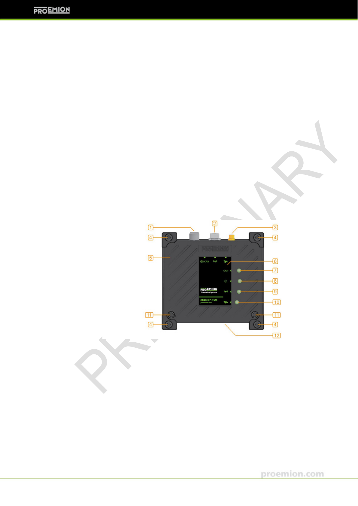
1. Main connector
7. CAN LED
PRELIMINARY 1 About the device
1 About the device
This chapter gives an overview of the device elements and functions and also
describes the intended use. It further lists the available device variants and the
product certifications.
For detailed specifications, please refer to chapter 9, Technical data.
1.1 Important device information
1.1.1 Device elements
Fig. 1-1 Device elements CANlink GSM / UMTS 5xxx (figure shows model 5101)
© 2012 PROEMION● V2.00 ● pe-cl-gsm-umts-5xxx-dm-e.docx ● created by InFi (JUL 19, 2012) ● preliminary release
PROEMION GMBH, Phone: +49 661 9490-600, Fax: -666, info@proemion.com, proemion.com 1
2. GSM/UMTS connector
3. GPS connector
4. Mounting holes
5. Aluminum enclosure
6. Front foil
8. ON LED
9. GSM/UMTS LED
10. GPS LED
11. Enclosure screws
12. T ype label (see next chapter)
CANlink GSM / UMTS 5xxx Device Manual
NOTICE
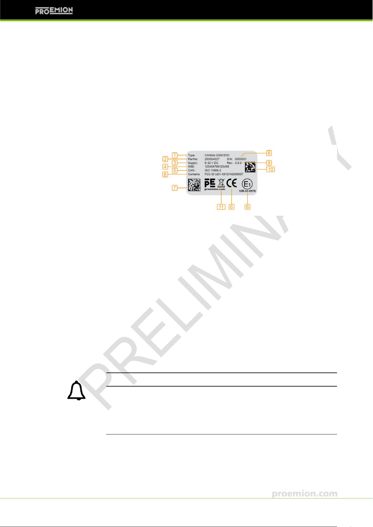
The device’s type label contains important information.
►
Solvents can destroy the
►
PRELIMINARY 1 About the device
1.1.1.1 Type label
The CANlink GSM / UMTS 5xxx type label is located at the bottom of the enclosure
and provides the following information:
Fig. 1-2 CANlink GSM / UMTS 5xxx type label
1. Device name and type
2. Product number
3. Power supply
4. International Mobile Station Equipment Identity (IMEI) number
5. CAN specification
6. Certifications
7. Traceability codes
8. Serial number
9. Hardware version
10. IMEI code
11. Disposal requirements (see chapter 7 Disposal)
Do not remove the type label.
imprint.
Do not contact the type label with any solvent-containing substance.
© 2012 PROEMION● V2.00 ● pe-cl-gsm-umts-5xxx-dm-e.docx ● created by InFi (JUL 19, 2012) ● preliminary release
PROEMION GMBH, Phone: +49 661 9490-600, Fax: -666, info@proemion.com, proemion.com 2

CANlink GSM / UMTS 5xxx Device Manual
DANGER
Danger due to possi
CANlink GSM / UMTS
networks
►
►
►
PRELIMINARY 1 About the device
1.1.2 Intended use
bly deficient data transmission
5xxx operates using radio signals and cellular
and is not authorized for use in safety-related applications.
Deficient network coverage, failure or malfunction of the device may lead to
deficient data transmission. Because of this, connection cannot be guaranteed
at all times under all conditions.
Do not operate the device in machines and applications where life depends on
the proper operation of this piece of equipment.
Never rely solely upon any wireless device for essential communications.
This device is designed to be used in systems which must be checked for
conformity with legal requirements prior to placing into operation. The
integrator of this device is responsible to check and comply with regional
directives and requirements.
CANlink GSM 5xxx interfaces are designed for transmitting data that is available
within a CAN network via GSM/GPRS, CANlink UMTS 5xxx devices additionally
via EDGE/UMTS/HSDPA.
The interfaces are suitable for use in mobile and stationary systems for industry,
small business area, and in agricultural and forestry machinery. They feature an
easy-to-install aluminum enclosure which can be bolted to a panel or mounted to a
DIN rail TS35. For more detailed information, see chapter 4.7 Mounting.
© 2012 PROEMION● V2.00 ● pe-cl-gsm-umts-5xxx-dm-e.docx ● created by InFi (JUL 19, 2012) ● preliminary release
PROEMION GMBH, Phone: +49 661 9490-600, Fax: -666, info@proemion.com, proemion.com 3
CANlink GSM / UMTS 5xxx Device Manual
NOTICE
IP
►
►
Compliance with CE
This device complies with the directives, standards, and normative documents
listed in
Compliance with FCC
This device complies with Part 15 of the FCC Rules. Operation is subject to the
following two conditions:
PRELIMINARY 1 About the device
CANlink GSM / UMTS 5xxx devices are IP 65-rated, i.e. protected against contact
as well as ingress of dust and against water jets against the enclosure (tested
under defined conditions of pressure and time).
65 protection is only ensured if all connectors are plugged in.
Before exposing the device to dust and water, plug in all connectors.
Do not immerse the device in water or other liquids.
1.1.3 Product conformity
For more detailed information on the respective tests, refer to chapter 10
Certifications.
1.1.3.1 CANlink GSM 5xxx
CANlink GSM 5xxx complies with the requirements of the following standards and
legal regulations:
chapter 10 Certifications.
1. this device may not cause harmful interference, and
2. this device must accept any interference received, including interference
that may cause undesired operation.
© 2012 PROEMION● V2.00 ● pe-cl-gsm-umts-5xxx-dm-e.docx ● created by InFi (JUL 19, 2012) ● preliminary release
PROEMION GMBH, Phone: +49 661 9490-600, Fax: -666, info@proemion.com, proemion.com 4

CANlink GSM / UMTS 5xxx Device Manual
Compliance wit h E1
This device has been approved by the KBA (Kraftfahrt-Bundesamt, Federal Office
for
Compliance with CE
This device complies with the directives, standards, and normative documents
listed in
Compliance with E1
PENDING
Compliance wit h FCC
This device complies with Part 15 of the FCC Rules. Operation is subject to the
following two conditions:
PRELIMINARY 1 About the device
Motor Traffic) to comply with Regulation No. 10.
1.1.3.2 CANlink UMTS 5xxx A1
CANlink UMTS 5xxx A1 (regional variant for frequency bands used in area 1:
Europe, etc.) complies with the requirements of the following standards and legal
regulations:
chapter 10 Certifications.
1.1.3.3 CANlink UMTS 5xxx A2
CANlink UMTS 5xxx A2 (regional variant for frequency bands used in area 2: USA,
etc.) complies with the requirements of the following standards and legal
regulations:
1. this device may not cause harmful interference, and
2. this device must accept any interference received, including interference
that may cause undesired operation.
© 2012 PROEMION● V2.00 ● pe-cl-gsm-umts-5xxx-dm-e.docx ● created by InFi (JUL 19, 2012) ● preliminary release
PROEMION GMBH, Phone: +49 661 9490-600, Fax: -666, info@proemion.com, proemion.com 5
CANlink GSM / UMTS 5xxx Device Manual
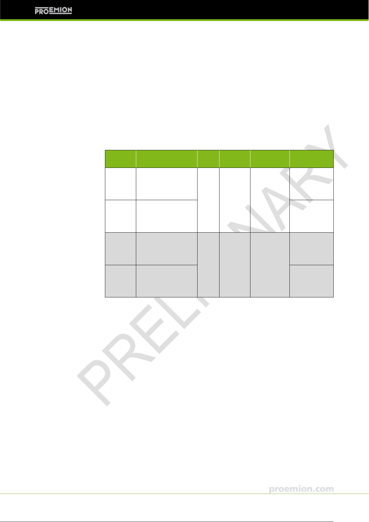
Model
GPS
I/Os
M12 main
connector
Product
number
5001
Power
Power
5102
2x analog IN 0...10 V
2x digital OUT
Wireless CAN
interface
PRELIMINARY 1 About the device
1.2 Device functions
CANlink GSM / UMTS 5xxx interfaces transmit data available on a CAN bus via
GSM telecommunication services and GPRS. In addition to data transmission via
GSM/GPRS, the CANlink UMTS devices use the EDGE, UMTS and HSDPA
standards to reduce data transmission latency and to improve data transfer rate.
Some device variants feature a GPS receiver for determining position data and/or
I/O functionality. For more detailed information on the different models, refer to
chapter 1.2.1 Available models.
For more detailed information on CANlink GSM / UMTS 5xxx and Proemion
functionalities, refer to chapter 3 Functionality and features
1.2.1 Available models
CANlink GSM / UMTS 5xxx is available with various options. The four ciphers
attached to the family name CANlink GSM or CANlink UMTS designate the
different variants.
You can find this name extension on the type label at the bottom of the enclosure.
There are many other standard or customized variants available, please contact
Proemion for more information.
The tables below list the distinctive features of the devices covered in this manual.
For detailed specifications, please refer to chapter 9, Technical data; for the
technical drawings refer to chapter 8, Technical drawings.
1.2.1.1 CANlink GSM 5xxx
5-pin CAN &
5-pin CAN &
253 004 028
253 004 027
5101
no no
yes no
© 2012 PROEMION● V2.00 ● pe-cl-gsm-umts-5xxx-dm-e.docx ● created by InFi (JUL 19, 2012) ● preliminary release
PROEMION GMBH, Phone: +49 661 9490-600, Fax: -666, info@proemion.com, proemion.com 6
yes
Tab. 1-1 Distinctive features of standard CANlink GSM 5xxx models
8-pin CAN &
Power & I/O
253 004 032
CANlink GSM / UMTS 5xxx Device Manual
Model
Frequency bands
(MHz)
GPS
I/Os
M12 main
connector
Product
number
GSM/GPRS/EDGE:
900/2100
GSM/GPRS/EDGE:
850/1900
900/2100
GSM/GPRS/EDGE:
850/1900
PRELIMINARY 1 About the device
1.2.1.2 CANlink UMTS 5xxx
Each CANlink UMTS model is available in two regional variants for use in areas
where different frequency bands are used:
• A1: Area 1 (Europe, etc.)
• A2: Area 2 (USA, etc.)
5201 A1
850/900/1800
UMTS/HSDPA:
5-pin
no no
CAN &
Power
5201 A2
850/900/1800/1900
UMTS/HSDPA:
GSM/GPRS/EDGE:
5302 A1
5302 A2
Tab. 1-2 Distinctive features of standard CANlink UMTS 5xxx models
850/900/1800
UMTS/HSDPA:
850/900/1800/1900
UMTS/HSDPA:
yes
2x an. IN
0...10 V
2x dig.
OUT
8-pin
CAN &
Power & I/O
1.2.2 Scope of supply
1.2.2.1 CANlink GSM / UMTS 5xxx single device
253 004 029
253 004 040
253 004 037
253 004 038
© 2012 PROEMION● V2.00 ● pe-cl-gsm-umts-5xxx-dm-e.docx ● created by InFi (JUL 19, 2012) ● preliminary release
PROEMION GMBH, Phone: +49 661 9490-600, Fax: -666, info@proemion.com, proemion.com 7
CANlink GSM / UMTS 5xxx is delivered with the following components:
‒ 1x CANlink GSM / UMTS 5xxx device

CANlink GSM / UMTS 5xxx Device Manual
Starter Kits
Product number
CANlink GSM 5101 Starter Kit
253 044 105
CANlink UMTS 5302 Starter Kit
253 000 106
PRELIMINARY 1 About the device
1.2.2.2 Starter Kits
CANlink GSM 5101 and CANlink UMTS 5302 are also available as a Starter Kit
encompassing the following components:
CANlink GSM 5 101 Starter Kit
‒ 1x CANlink GSM 5101 device
‒ 1x CANview USB gateway
‒ 1x GSM/GPS antenna
‒ 1x CAN/power cable
‒ 1x CAN bus termination
‒ 1x Power supply
‒ 1x RM System Tools CD
CANlink UMTS 5302 Starter Kit
‒ 1x CANlink UMTS 5302 device (variant A1 or A2)
‒ 1x CANview USB gateway
‒ 1x GSM/UMTS/GPS antenna
‒ 1x CAN/power cable
‒ 1x CAN bus termination
‒ 1x Power supply
‒ 1x RM System Tools CD
On the RM System Tools CD, you will find documentation and various software
tools for configuring and deploying the device.
Tab. 1-3 CANlink GSM / UMTS 5xxx Starter Kits
For a list of separately available software and accessories, refer to chapter 1.2.3.
© 2012 PROEMION● V2.00 ● pe-cl-gsm-umts-5xxx-dm-e.docx ● created by InFi (JUL 19, 2012) ● preliminary release
PROEMION GMBH, Phone: +49 661 9490-600, Fax: -666, info@proemion.com, proemion.com 8

CANlink GSM / UMTS 5xxx Device Manual
Software
Product number
RM System Tools CD
157 002 059
Accessories
Product number
CAN Cable M12 5-Pin / open
wire ends
136 000 005
CAN Cable 5-Pin M12 \ 9-PIN SUBD
CAN connector (f)
136 000 009
plug
CAN Cable 5m M12 8-Pin / open
CAN cable 5m with 8-pin female connector
136 000 011
GPS flat antenna
GPS connector SMA-male
157 000 020
GSM Quad Band flat antenna
GSM-connector FME-female
GSM/UMTS/GPS combi flat antenna
GPS connector SMA-male
157 000 084
Magnetic pad for GSM/UMTS/GPS combi
antenna 157000084
141 000 008
Adapter SM A-male to FME-male
157 000 030
Adapter SM A-female to FME-female
157 000 039
DIN rail mounting kit
141 000 010
PRELIMINARY 1 About the device
1.2.3 Software and accessories
Round 5 pin CAN connector (f) to open
Round 5 pin CAN connector (f) to SUBD 9
CAN Cable 5-Pin \ 9-pin SUBD Power
Round 5 pin CAN connector (f) to SUBD 9
CAN connector (f) with additional power
Roof mounting, dxh 76x21 mm,
cable RG174, l=5m,
Roof mounting, dxh 76x21 mm,
cable RG174, l=3.5 m,
850/900/1800/1900 MHz,
dashboard/window mounting
wxhxd 100x66x21 mm
cable RG174, l=3 m
GSM/UMTS: 850/900/1800/1900/2100 MHz
GSM/UMTS-connector FME-female
136 000 028
157 000 028
© 2012 PROEMION● V2.00 ● pe-cl-gsm-umts-5xxx-dm-e.docx ● created by InFi (JUL 19, 2012) ● preliminary release
PROEMION GMBH, Phone: +49 661 9490-600, Fax: -666, info@proemion.com, proemion.com 9

CANlink GSM / UMTS 5xxx Device Manual
For further information see our website:
proemion.com
or contact our support team:
support.rmcan.com
PRELIMINARY 1 About the device
1.3 Service and support
The most recent driver, software, firmware, and documentation versions are
available for download from the website of our partner RM Michaelides
rmcan.com
Customer Login
User: support
Password: canbyrm
© 2012 PROEMION● V2.00 ● pe-cl-gsm-umts-5xxx-dm-e.docx ● created by InFi (JUL 19, 2012) ● preliminary release
PROEMION GMBH, Phone: +49 661 9490-600, Fax: -666, info@proemion.com, proemion.com 10

CANlink GSM / UMTS 5xxx Device Manual
These instructions are part of the device. They contain text and illustrations for the
correct handling of the module and must be read before
Before deploying the device described in this document, read the entire manual
including all safety information.
Adhere to the information contained in this manual and other product
documentation. Non
with use as prescribed below, wrong installation or handling can result in serious
harm concerning the safety of people and plant.
Keep this manual for future use and make all information available to anyone
deploying the device
T
and plant. It is not permitted and leads to an exclusion of any liability and warranty
claims.
The device must be installed, connected and put into
electrician.
In the
This device is designed to be used in systems which must be checked for
conformity with legal requirements prior to placing into operati
this device is responsible to check and comply with regional directives and
requirements.
PRELIMINARY 2 Safety information
2 Safety information
In this chapter, you will find important information on how to avoid life-threatening
situations and injuries and how to prevent product damage.
2.1 General information
-observance of the notes, operation that is not in accordanc e
, even after installation.
ampering with the device can lead to considerable risks for the safety of people
event of malfunctions or uncertainties, please contact the manufacturer.
installation or use.
operation by a qualified
on. The integrator of
© 2012 PROEMION● V2.00 ● pe-cl-gsm-umts-5xxx-dm-e.docx ● created by InFi (JUL 19, 2012) ● preliminary release
PROEMION GMBH, Phone: +49 661 9490-600, Fax: -666, info@proemion.com, proemion.com 11

CANlink GSM / UMTS 5xxx Device Manual
DANGER
Danger due to
CANlink GSM / UMTS
networks
►
►
DANGER
Danger
►
5xxx's
►
PRELIMINARY 2 Safety information
2.2 Safety advice
2.2.1 General
possibly deficient data transmission
5xxx operates using radio signals and cellular
and is not authorized for use in safety-related applications.
Deficient network coverage, failure or malfunction of the device may lead to
deficient data transmission. Because of this, connection cannot be guaranteed
at all times under all conditions.
Do not operate the device in machines and applications where life depends on
the proper operation of this piece of equipment.
Never rely solely upon any wireless device for essential communications.
2.2.2 Health care
of interference caused by RF energy
Medical equipment ma y be sensitive to RF energy.
When in a hospital or other health care facility, observe the restrictions on the
use of mobiles. Switch CANlink GSM / UMTS 5xxx off, if instructed to do so by
the guidelines posted in sensitive areas.
The operation of cardiac pacemakers, other implanted medical equipment and
hearing aids can be affected by interference from CANlink GSM / UMTS
antennas placed close to the device.
If in doubt about potential danger, contact a physician or the manufacturer of
the equipment to verify that it is properly shielded. Pacemaker patients are
advised to keep CANlink GSM / UMTS 5xxx and its antennas away from the
pacemaker while it is on.
© 2012 PROEMION● V2.00 ● pe-cl-gsm-umts-5xxx-dm-e.docx ● created by InFi (JUL 19, 2012) ● preliminary release
PROEMION GMBH, Phone: +49 661 9490-600, Fax: -666, info@proemion.com, proemion.com 12

CANlink GSM / UMTS 5xxx Device Manual
DANGER
Danger
►
►
DANGER
Danger of explosion
can
►
►
PRELIMINARY 2 Safety information
2.2.3 Air traffic
of interference caused by RF energy
The operation of wireless appliances in an aircraft is forbidden to prevent
interference with communications systems. Failure to observe these
instructions may lead to the suspension or denial of cellular services to the
offender, legal action, or both.
Switch off CANlink GSM / UMTS 5xxx before boarding an aircraft.
Make sure it cannot be switched on inadvertently.
2.2.4 Explosives
Operation of any electrical equipment in potentially explosive atmospheres
constitute a safety hazard.
Adhere to the respective regulations and precautions when you are near petrol
stations, fuel depots, chemical plants or where blasting operations are in
progress.
Do not mount the antenna in the close environment of fuel tanks, vessels with
explosives and insufficient l y shiel ded el ectr onic de vic e s.
© 2012 PROEMION● V2.00 ● pe-cl-gsm-umts-5xxx-dm-e.docx ● created by InFi (JUL 19, 2012) ● preliminary release
PROEMION GMBH, Phone: +49 661 9490-600, Fax: -666, info@proemion.com, proemion.com 13

CANlink GSM / UMTS 5xxx Device Manual
CAUTION
Danger due to
►
►
CAUTION
D
►
PRELIMINARY 2 Safety information
2.2.5 Antennas
absorption of RF energy
Mobile communication devices may pose a health risk when operated in the
close proximity of persons.
Install the antenna(s) used for the CANlink GSM / UMTS 5xxx devices to
provide a separation distance of at least 20 cm / 8 inches from all persons.
Do not operate them in conjunction or co-locate them with any other antenna
or transmitter.
2.2.6 Electronic equipment
anger of interference cau sed by RF energy
CANlink GSM / UMTS 5xxx receives and transmits radio frequency energy
while switched on. Interference can occur if it is used close to TV sets, radios,
computers or inadequately shielded equipment.
Follow any special regulations and always switch off the CANlink GSM / UMTS
5xxx wherever forbidden, or when you suspect that it may cause interference
or danger.
© 2012 PROEMION● V2.00 ● pe-cl-gsm-umts-5xxx-dm-e.docx ● created by InFi (JUL 19, 2012) ● preliminary release
PROEMION GMBH, Phone: +49 661 9490-600, Fax: -666, info@proemion.com, proemion.com 14

CANlink GSM / UMTS 5xxx Device Manual
NOTICE
►
he reverse
voltage protection of the power supply. Applying a reversed voltage in this case
►
►
IP
►
►
The maximum torque for fixing the enclosure screws is 1.5 Nm.
►
►
Operation without antennas
►
►
PRELIMINARY 2 Safety information
2.3 Avoidance of property damage
Do not connect the housing to Ground externally. This will suspend t
will destroy the supply circuits.
Disconnect the device externally before handling it. Also disconnect an y
independently supplied output load circuits.
To avoid damage to the device, connect/disconnect the main connector only if
the power supply to the device is switched off.
65 protection is only ensured if all connectors are plugged in.
Before exposing the device to dust and water, plug in all connectors.
Do not immerse the device in water or other liquids.
When opening/closing the enclosure, do not exceed this value.
The device can only be repaired by the manufacturer.
can destroy the radio modem.
Do not operate the device without antennas.
To prevent misuse immediately inform your network operator in case of loss or
theft of the SIM card or the radio modem.
2.4 FCC notice
The devices covered in the manual may only be used in mobile or stationary
systems in which under normal operating conditions the separation distance
between the antenna(s) and all persons is at least 20 cm (approx. 8 inches). The
antenna(s) must further not be co-located or operated in conjunction with any
antenna or transmitter.
© 2012 PROEMION● V2.00 ● pe-cl-gsm-umts-5xxx-dm-e.docx ● created by InFi (JUL 19, 2012) ● preliminary release
PROEMION GMBH, Phone: +49 661 9490-600, Fax: -666, info@proemion.com, proemion.com 15

CANlink GSM / UMTS 5xxx Device Manual
Note: This equipment has been tested and found to comply with the limits for a
Class B digital device, pursuant to part 15 of the FCC Rules. These limits are
designed to provide reasonable protection against harmful interference in a
residential installation. This equipment generates, uses
frequency energy and, if not installed and us ed in acc ordanc e with the ins truc ti ons,
may cause harmful interference to radio communications. However, there is no
guarantee that interference will not occur in a particular installation.
equipment does cause harmful interference to radio or television reception, which
can be determined by turning the equipment off and on, the user is encouraged to
try to correct the interference by one or more of the following measures:
►
►
►
►
Modifications not expressly approved by the manufacturer could void the user's
authority to operate the equipment under FCC rules.
PRELIMINARY 2 Safety information
According to FCC requirements, the antenna gai n, including cable loss, must not
exceed the limits of 7.3 dBi in the 850 MHz Cellular band and 12.7 dBi in the PCS
1900 MHz band (CANlink GSM 5xxx devices) or 7.2 dBi in the 850 MHz cellular
band and 3.5 dBi in the PCS 1900 MHz band respectively (CANlink UMTS 5xxx
devices).
Compliance of CANlink GSM / UMTS 5xxx devices in all final product
configurations is the responsibility of the integrator.
Reorient or relocate the receiving antenna.
Increase the separation between the equipment and receiver.
Connect the equipment into an outlet on a circuit different from that to which
the receiver is connected.
Consult the dealer or an experienced radio/TV technician for help.
2.5 Warranty and liability
We assume no liability for defects caused by normal wear, external influences, and
errors of installation, operating or maintenance. This also applies if the customer
itself or third parties without our approval modify the components of our products
(e.g. devices, elements or additional hardware facilities; programs or program
elements of the software).
and can radiate radio
If this
© 2012 PROEMION● V2.00 ● pe-cl-gsm-umts-5xxx-dm-e.docx ● created by InFi (JUL 19, 2012) ● preliminary release
PROEMION GMBH, Phone: +49 661 9490-600, Fax: -666, info@proemion.com, proemion.com 16

CANlink GSM / UMTS 5xxx Device Manual
Some device variants feature a GPS receiver for determining position data and/or
I/O functionality.
chapter
GPS
I/Os
GPRS/EDGE/
UMTS/HSDPA
PRELIMINARY 3 Functionality and features
3 Functionality and features
In this chapter, you will find information on the device functionality. Further, the
device features, such as connectors and pin assignments, interfaces, indicator and
operating elements, etc., are described in detail.
3.1 Functional range
CANlink GSM / UMTS 5xxx devices allow for communication via CAN, GSM, and
the Internet.
For more detailed information on the different models, refer to
1.2.1 Available models.
The GPS enables the devices to determine their position using the Global
Positioning System. The position data can then be transmitted via GSM/UMTS to
another GSM/PSTN/ISDN/UMTS device or made available to the connected CAN
bus system.
The data of the I/Os can also be made available to the CAN bus or be transmitted
via GSM/UMTS. The non-volatile logging memory can be used to collect CAN data
over a period of time. The complete contents of the logging memory can then be
transmitted via GPRS/UMTS in one burst.
All CANlink GSM / UMTS 5xxx devices feature GPRS service; the CANlink UMTS
5xxx devices additionally feature EDGE/UMT S/HSDPA services. Beyond the GSM
functionality, these services allow for communication with web servers at higher
data rates. The communication is based on the TCP/IP protocol.
Using these services requires a connection to an Internet server.
© 2012 PROEMION● V2.00 ● pe-cl-gsm-umts-5xxx-dm-e.docx ● created by InFi (JUL 19, 2012) ● preliminary release
PROEMION GMBH, Phone: +49 661 9490-600, Fax: -666, info@proemion.com, proemion.com 17

CANlink GSM / UMTS 5xxx Device Manual
For further information about a standard or customized solution see the Proemion
website
If you want to integrate
5xxx into your own infrastructure and
require further information, please contact our support team at
support.rmcan.com
For more detailed information on using the
corresponding Software Manuals. You can find these manuals on the
Tools CD
PRELIMINARY 3 Functionality and features
As a standard solution for this, Proemion offers various software and server
solutions:
• With Proemion Real-Time, you can access CAN data of monitored
machines or vehicles in near real-time – regardless of your current
location.
• The Proemion Web Portal solution provides comprehensive options for
machine park and fleet management via the Internet, such as reporting,
optimizing routes and processes or theft protection with the help of
geofencing.
For more detailed information on Proemion functionalities, refer to chapter
3.1.1 Operating modes.
www.proemion.com
CANlink GSM / UMTS
RM System Tools, please refer to the
.
3.1.1 Operating modes
CANlink GSM / UMTS 5xxx can be operated in two different modes:
• Real-time mode
• File-transfer mode
3.1.1.1 Real-time mode
RM System
CAN messages are received by the device and sent via the Proemion server to the
remote PC. On this computer there may be an analysis software which can handle
the CAN messages. A bi-directional data transfer is possible. When higher layer
protocols are used, a special firmware and software adaptation may be necessary
due to the delay times caused by the GSM/UMTS network. For this operation a
permanent connection (GSM/UMTS coverage) is necessary.
© 2012 PROEMION● V2.00 ● pe-cl-gsm-umts-5xxx-dm-e.docx ● created by InFi (JUL 19, 2012) ● preliminary release
PROEMION GMBH, Phone: +49 661 9490-600, Fax: -666, info@proemion.com, proemion.com 18

CANlink GSM / UMTS 5xxx Device Manual
NOTICE
►
he reverse
Applying a reversed voltage in this case
►
PRELIMINARY 3 Functionality and features
3.1.1.2 File-transfer mode
In this operation mode the CANlink GSM / UMT S 5xxx either logs specific CAN
messages and GPS position data according to its configuration and sends them in
®
a special format to the Proemion server or a CANopen
master controller can send
files of any format to the Proemion server using the CANlink GSM / UMTS as a
kind of gateway or router to the Proemion server. The devices have an internal
non-volatile memory which allows to store the files in case of a GSM outage. When
the connection is recovered the files are sent to the server automatically.
3.2 Connectors
CANlink GSM / UMTS 5xxx is equipped with the following connectors:
• 1x Main connector
• 1x GSM connector
• 1x GPS connector (models with GPS functionality only)
3.2.1 Main connector
The main connector serves for
• connecting the device to the CAN bus
• supplying the device with power
Therefore, CANlink GSM / UMTS 5xxx has to be connected to the CAN bus in
order to operate.
Do not connect the housing to Ground externally. This will suspend t
voltage protection of the power supply.
will destroy the supply circuits.
To avoid damage to the device, connect/disconnect the main connector only if
the power supply to the device is switched off.
© 2012 PROEMION● V2.00 ● pe-cl-gsm-umts-5xxx-dm-e.docx ● created by InFi (JUL 19, 2012) ● preliminary release
PROEMION GMBH, Phone: +49 661 9490-600, Fax: -666, info@proemion.com, proemion.com 19
CANlink GSM / UMTS 5xxx Device Manual
Depending on the model, the main connector has different functions and a different
number of pins:
For more detailed information on the di
Available
CAN/power connector
5-pin M12, male, A-coded, front view
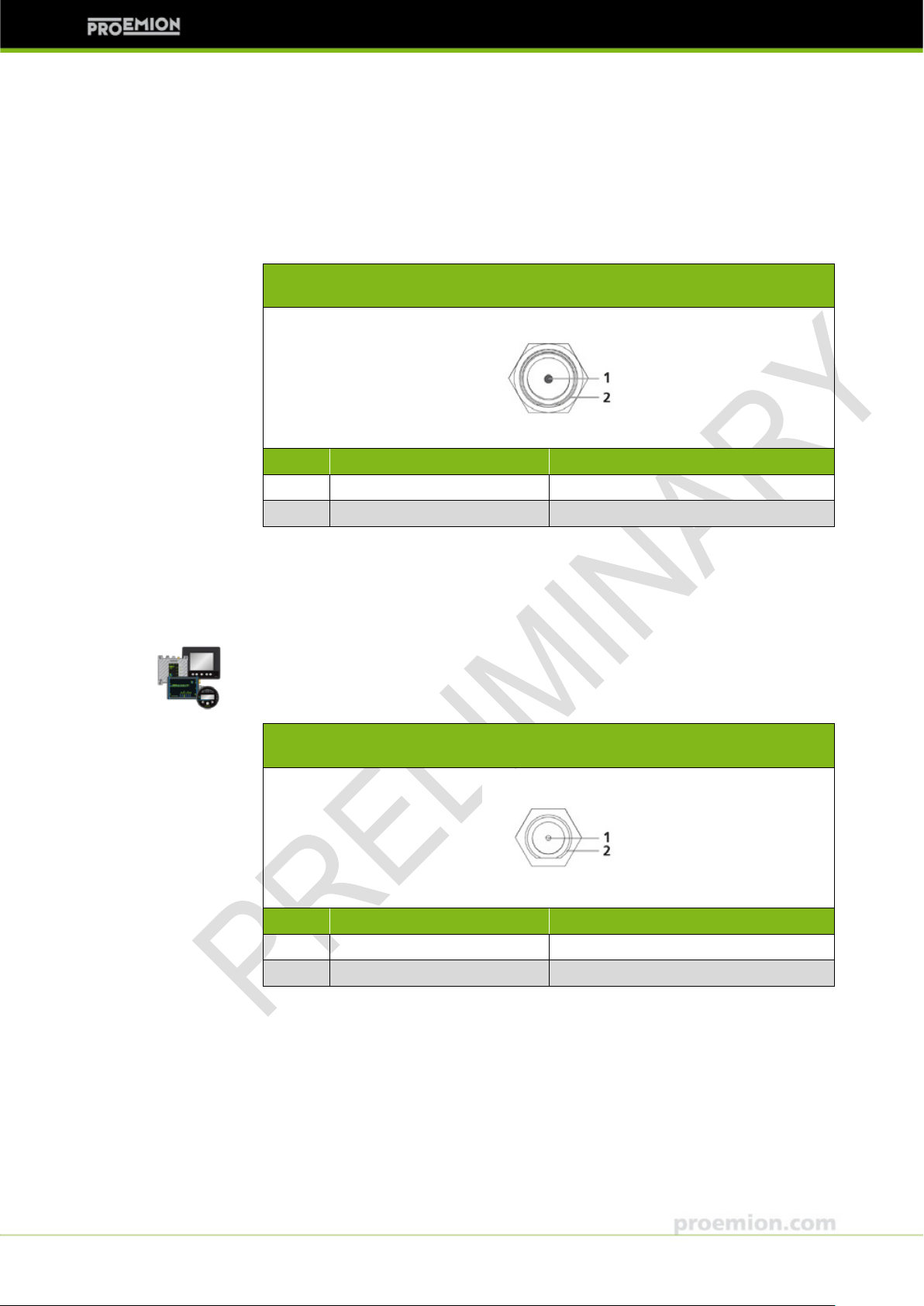
Pin
Designation
Color
Description
1
Ground
Brown
Power supply
2
VCC 6 … 32 V DC
White
Power supply
3
n.c. (not connected)
Blue
4 CAN-High
Black
CAN
5
CAN-Low
Grey, green
CAN
PRELIMINARY 3 Functionality and features
• Models without I/O functionality (5001, 5101 & 5201):
5-pin M12 male, CAN/power
• Models with I/O functionality (5102 & 5302):
8-pin M12 male, CAN/power & I/O functionality
fferent models, refer to chapter 1.2.1
models.
3.2.1.1 5-pin M12 CAN/power connector
The table and drawing below show the pin assignment of the 5-pin M12 connector.
The colors stated in the table belo w are the conductor colors of the cable listed in
the section Accessories and provided in the Starter Kit.
Fig. 3-1 5-pin M12 CAN/power connector with pin assignment
© 2012 PROEMION● V2.00 ● pe-cl-gsm-umts-5xxx-dm-e.docx ● created by InFi (JUL 19, 2012) ● preliminary release
PROEMION GMBH, Phone: +49 661 9490-600, Fax: -666, info@proemion.com, proemion.com 20
CANlink GSM / UMTS 5xxx Device Manual
CAN/power c o n n ector
8-pin M12, male, A-coded, front view
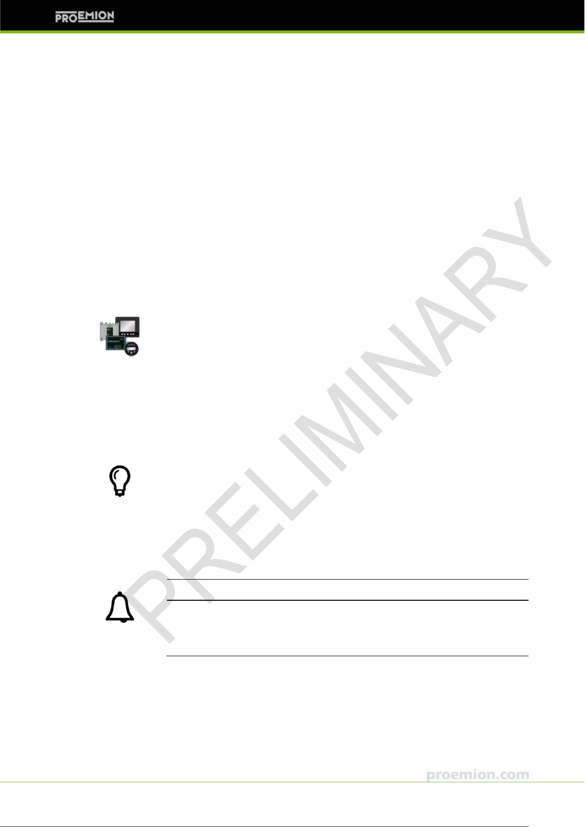
Pin
Designation
Color
Description
1
Analog IN 1
White
I/O 2 Analog IN 2
Brown
I/O
3
Digital OUT 1
Green
I/O 4 Digital OUT 2
Yellow
I/O 5 CAN-High
Grey
CAN
6
CAN-Low
Pink
CAN
7
VCC 6 … 32 V DC
Blue
Power supply
8
Ground
Red/shield
Power supply
PRELIMINARY 3 Functionality and features
3.2.1.2 8-pin M12 CAN/power & I/O connector
The table and drawing below show the pin assignment of the 8-p in M12 connector.
The colors stated in the table below are the conductor colors of the cable listed in
the section Accessories and provided in the Starter Kit.
Fig. 3-2 8-pin M12 CAN/power & I/O connector with pin assignment
The additional I/Os consist of two analog inputs that have an input range of
0…10 V DC. Optionally they can also be used as digital inputs with a maximum
input voltage of up to 32 V DC.
The short-circuit proof digital outputs are PnP switching and can be diagnosed by
the CANlink GSM / UMTS 5xxx device. They will apply the supply voltage of the
device to the output pins and are able to provide a current of up to 500 mA.
© 2012 PROEMION● V2.00 ● pe-cl-gsm-umts-5xxx-dm-e.docx ● created by InFi (JUL 19, 2012) ● preliminary release
PROEMION GMBH, Phone: +49 661 9490-600, Fax: -666, info@proemion.com, proemion.com 21
CANlink GSM / UMTS 5xxx Device Manual
GSM/UMTS connector
FME, male, front view
Pin
Designation
Description
1
Signal
GSM/UMTS
2
Ground
Shield/housing
The models 51
GPS connector
SMA, female, front view
Pin
Designation
Description
1
Signal
GPS
2
Ground
Shield/housing
PRELIMINARY 3 Functionality and features
3.2.2 GSM/UMTS connector
Fig. 3-3 FME GS M/UMTS connector with pin assignment
3.2.3 GPS connector
01, 5102, 5301 & 5302 are equipped with a GPS connector.
© 2012 PROEMION● V2.00 ● pe-cl-gsm-umts-5xxx-dm-e.docx ● created by InFi (JUL 19, 2012) ● preliminary release
PROEMION GMBH, Phone: +49 661 9490-600, Fax: -666, info@proemion.com, proemion.com 22
Fig. 3-4 SMA GPS connector with pin assignment
CANlink GSM / UMTS 5xxx Device Manual
Depending on the model, CANlink GSM / UMTS 5xxx is equipped with 3 or 4 LEDs
respectively.
Models without
For a list of
models
If green and red
NOTICE
If all LEDs are constantly
(
►
PRELIMINARY 3 Functionality and features
3.3 Indicator elements
The device is equipped with the following indicator elements:
• 1x CAN LED
• 1x ON LED
• 1x GSM/UMTS LED
• 1x GPS LED (models with GPS functionality only)
3.3.1 LEDs
GPS functionality do not feature a GPS LED.
the different models and their features, see chapter 1.2.1 Available
.
All LEDs are bicolor (green and red) and signal the device status with various
flashing codes.
are simultaneously on, the LED will appear orange.
The following tables describe the LED light characteristics and the corresponding
device status.
green at the same time and synchronously flashing red
i.e. orange), the device is in firmware update mode.
Do not switch the device off.
© 2012 PROEMION● V2.00 ● pe-cl-gsm-umts-5xxx-dm-e.docx ● created by InFi (JUL 19, 2012) ● preliminary release
PROEMION GMBH, Phone: +49 661 9490-600, Fax: -666, info@proemion.com, proemion.com 23
 Loading...