

MANUALE UTENTE - INSTRUCTION MANUAL
Sistema di Discussione Wireless
Wireless Discussion System
DSWKIT

2

INDICE
1. PRECAUZIONI D’USO ............................................................................................................. 4
2. DESCRIZIONE ......................................................................................................................... 6
3. FUNZIONI E CONTROLLI PANNELLO FRONTALE .............................................................. 7
4. FUNZIONI E CONTROLLI PANNELLO POSTERIORE ........................................................... 7
5. FUNZIONI E CONTROLLI CONSOLLE MICROFONICA WIRELESS BMW ........................... 8
6. COME UTILIZZARE IL SISTEMA ............................................................................................ 9
7. RICARICA DELLE BATTERIE ............................................................................................... 11
8. TIPO DI CONNESSIONI ......................................................................................................... 12
9. CONTENUTO DELLA CONFEZIONE .................................................................................... 12
10. CARATTERISTICHE TECNICHE ........................................................................................... 13
3
1. PRECAUZIONI D’USO
AVVERTENZA:Per ridurre il rischio di folgorazione, non rimuovere il coperchio (o il pannello posteriore). All’interno non sono contenute parti
ATTENZIONE: Per ridurre il rischio d’incendio o di folgorazione, non esporre questo apparecchio alla pioggia o all’umidità.
Questo simbolo, ove compare, segnala la presenza di un voltaggio pericoloso non isolato all’interno del corpo dell’apparecchio –
Questo simbolo, ove appare, segnala, importanti istruzioni d’uso e manutenzione nel testo allegato. Leggere il manuale
RACCOMANDAZIONI:
Tutte le istruzioni di sicurezza e funzionamento devono essere lette prima di mettere in funzione l’apparecchio.
Conservare le istruzioni:
Le istruzioni di sicurezza e di funzionamento devono essere conservate per un futuro riferimento.
Il presente manuale è parte integrante del prodotto e lo deve accompagnare in caso di eventuali cambi di proprietà. In questo modo il nuovo
proprietario potrà conoscere le istruzioni relative a installazione, funzionamento e sicurezza.
Prestare attenzione:
Tutte le avvertenze sull’apparecchio e nelle istruzioni di funzionamento devono essere seguite fedelmente.
Osservare tutti gli avvertimenti.
Seguire le istruzioni:
Tutte le istruzioni per il funzionamento e per l’utente devono essere seguite.
riparabili dall’utente; affidare la riparazione a personale qualificato.
voltaggio sufficiente a costituire un rischio di folgorazione.
.
Le note precedute dal simbolo contengono importanti informazioni sulla sicurezza: leggerle con particolare attenzione.
ISTRUZIONI DI SICUREZZA IN DETTAGLIO.
Acqua ed umidità:
L’apparecchio non deve essere utilizzato in prossimità di acqua (per es. vicino a vasche da bagno, lavelli da cucina, in prossimità di piscine
ecc.).
Ventilazione:
L’apparecchio deve essere posto in modo tale che la sua collocazione o posizione non interferisca con l’adeguata ventilazione. Per esempio,
l’apparecchio non deve essere collocato su un letto, copri-divano, o superfici simili che possono bloccare le aperture di ventilazione, o posto in
una installazione ad incasso, come una libreria o un armadietto che possono impedire il flusso d’aria attraverso le aperture di ventilazione.
Calore:
L’apparecchio deve essere posto lontano da fonti di calore come radiatori, termostati, asciuga biancheria, o altri apparecchi che producono
calore.
Alimentazione:
• L’apparecchio deve essere collegato soltanto al tipo di alimentazione descritto nelle istruzioni d’uso o segnalato sull’apparecchio.
• Se la spina in dotazione non combacia con la presa, rivolgersi ad un elettricista per farsi installare una presa appropriata.
Messa a terra o polarizzazione:
• Si devono prendere precauzioni in modo tale che la messa a terra e la polarizzazione dell’ apparecchio non siano pregiudicate.
• Le parti metalliche dell’apparecchiatura sono collegate a massa tramite il cavo d’alimentazione.
• Se la presa utilizzata per alimentazione non possiede collegamento a massa, rivolgersi ad un elettricista qualificato per fare collegare
l’apparato a massa tramite il terminale.
Protezione del cavo di alimentazione:
Il cavo di alimentazione elettrica deve essere installato in modo che non venga calpestato o pizzicato da oggetti posti sopra o contro, prestando
particolare attenzione a cavi e spine, prese a muro.
Pulizia:
• Quando l’unità deve essere pulita, è possibile eliminare la polvere utilizzando un getto d’aria compressa o un panno inumidito.
• Non pulire l’unità utilizzando solventi quali trielina, diluenti per vernici, fluidi, alcol, fluidi ad alta volatilità o altri liquidi infiammabili.
Periodi di non utilizzo:
Il cavo di alimentazione dell’apparecchio deve essere staccato dalla presa se rimane inutilizzato per un lungo periodo.
Ingresso di liquidi o oggetti:
Si deve prestare attenzione che non cadano oggetti e non si versino liquidi nel corpo dell’apparecchio attraverso le griglie.
4

Uso sicuro della linea d’alimentazione:
• Quando si scollega l’apparato alla rete tenere saldamente sia la spina che la presa.
• Quando l’unità non viene utilizzata per un periodo prolungato, interrompere l’alimentazione estraendo la spina dalla presa
dell’alimentazione
• Per evitare danni alla linea d’alimentazione dell’apparato, non mettere in trazione il cavo d’alimentazione e non utilizzare un cavo
attorcigliato.
• Per evitare il danneggiamento del cavo d’alimentazione dell’apparato, assicurarsi che questo non venga calpestato o schiacciato da oggetti
pesanti.
Spostamento dell’unità:
Prima di ogni spostamento, verificare che l’unità sia spenta. Il cavo d’alimentazione deve essere estratto dalla presa, così come i collegamenti
dell’unità con altre linee.
Non smontare l’unità:
Non tentare di smontare né riparare da soli l’unità. Per qualsiasi problema non risolvibile con l’aiuto del presente manuale, rivolgersi a un
tecnico qualificato o consultare la nostra compagnia. Qualsiasi uso non appropriato può causare incendi o scosse elettriche.
Malfunzionamenti:
• Non tentare mai di eseguire riparazioni diverse da quelle descritte nel presente manuale.
• Contattare un centro di servizio autorizzato o del personale altamente qualificato nei seguenti casi:
- Quando l’apparato non funziona o funziona in modo anomalo.
- Se il cavo d’alimentazione o la spina sono danneggiati.
- Sono penetrati oggetti estranei o è stato versato del liquido nell’apparecchio.
- L’apparecchio è stato esposto alla pioggia.
- L’apparecchio non sembra funzionare normalmente o presenta un evidente
cambiamento nelle prestazioni.
- L’apparecchio è caduto, o il corpo è danneggiato.
Manutenzione:
L’utente non deve tentare di riparare l’apparecchio al di là di quanto descritto nelle istruzioni di funzionamento. Ogni altra riparazione deve essere
affidata a personale specializzato.
IMPORTANTI NORME DI SICUREZZA:
• Installare seguendo le istruzioni.
• Il voltaggio d’alimentazione dell’unità è abbastanza elevato per evitare il rischio di scosse elettriche, non installare, collegare o sconnettere
l’alimentazione quando l’apparato è acceso.
• Non aprire mai l’apparecchiatura: all’interno non esistono parti utilizzabili dall’utente.
• Se si avverte uno strano odore proveniente dall’apparato, spegnerlo immediatamente e sconnettere il cavo dell’alimentazione.
• Non ostruire le griglie di ventilazione dell’apparato.
• Evitare che l’unità lavori in sovraccarico per tempo prolungato.
• Non forzare i comandi (pulsanti, controlli, ecc.)
• Avvitare completamente i terminali a vite degli altoparlanti per garantire la sicurezza dei contatti.
•
Per ragioni di sicurezza, non annullare il collegamento a massa della spina. Il collegamento a massa è necessario per salvaguardare la
sicurezza dell’operatore
• Utilizzare unicamente i connettori e gi accessori specificati dal produttore.
• L’apparato deve essere collocato in un rack metallico (vedi INSTALLAZIONE) e tenuto lontano da:
¾ Luoghi umidi
¾ Esposizione diretta a fonti di calore (come luce solare).
¾ Luoghi non sufficientemente ventilati
• In presenza di temporali con fulmini o quando l’apparato non è utilizzato, estrarre la spina d’alimentazione dalla presa.
•
Per prevenire il rischio di incendi e scosse elettriche, è necessario tenere l’apparato lontano da spruzzi e gocce. Sopra l’apparato non
devono essere collocati vasi o altri oggetti contenenti liquidi. In caso si verifichino interferenze nel circuito di provenienza, il valore di THD
sarà superiore al 10%. Non installare questo apparato in una libreria o in altri luoghi a spazio ristretto
• PROEL S.P.A. declina ogni responsabilità in caso di scorretta installazione dell’unità.
5

Grazie per aver scelto un prodotto Proel e della fiducia riposta nel nostro marchio, sinonimo di professionalità,
accuratezza, elevata qualità ed affidabilità. Tutti i nostri prodotti sono conformi alle normative CE per utilizzazione
continua in impianti di diffusione sonora.
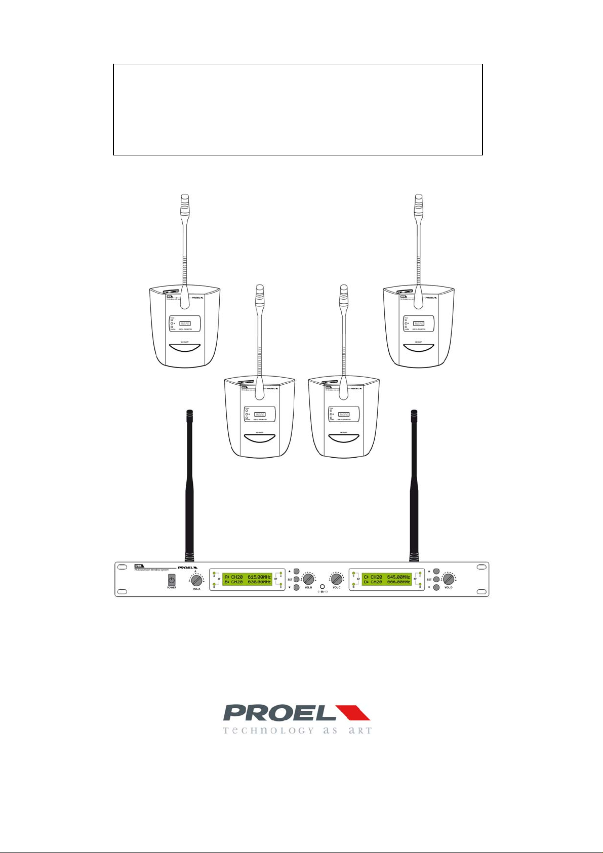
2. DESCRIZIONE
Il sistema di Discussione senza fili si compone di unità ricevente denominata DWS corredata di quattro basi
wireless BMW e di un carica batterie.
Il sistema lavora in tecnologia UHF PLL ed è dotato di circuito anti interferenza e sistema TONE LOCK.
Due range di frequenza disponibili: a: 610÷ 670 MHz e b:730÷ 790MHz
In ogni range di frequenza possono operare contemporaneamente fino a 3 unità riceventi per un massimo di 12
postazioni. Utilizzando entrambi i range di frequenza possiamo ottenere un sistema fino a 6 unità riceventi (3 tipo a e 3
tipo b) per un massimo di 24 postazioni (12 tipo a – 12 tipo b) operanti contemporaneam ente.
Ogni Unità centrale dispone di 4 canali:
Range a:
Canale A: banda 610.00 ÷ 624.75 MHz
Canale B: banda 625.00 ÷ 639.75 MHz
Canale C: banda 640.00 ÷ 654.75 MHz
Canale D: banda 655.00 ÷ 669.75 MHz
Range b:
Canale A: banda 730.00-744.75MHz
Canale B: banda 745.00-759.75MHz
Canale C: banda 760.00-774.75MHz
Canale D: banda 775.00-789.75MHz
Ciascuna base BMW opera esclusivamente in una delle quattro bande (facilmente individuabile sul fondo della base
stessa (fig.3, rif.11). La base è alimentata mediante una coppia di batterie ricaricabili tipo AA 1.2V 1200mA capaci di
conferire una durata di 8-9 h con selettore di potenza di trasmissione in posizione Hi e di 10-11 h con selettore in
posizione Lo. In alternativa può essere impiegata una normalissima coppia di batterie usa e getta tipo AA da 1,5V
Funzioni principali:
• Doppio Display
• Tasti di navigazione
• Controllo del livello di ogni singola base microfonica
• Tecnologia all’infrarosso per l’impostazione della frequenza operativa
• Uscita Bilanciata e sbilanciata mixata
• Singole uscite per ogni canale
• Modalità frequenze canalizzate o Tuning
• Controllo dello Squelch separato per ogni singaola Banda
• Consolle wireless con display ed anello luminoso per indicare la condizione operativa
• Portata 50/60 mt
• Case in metallo da 1 unità rack 19” standard
Prodotto conforme alla normativa CE
6
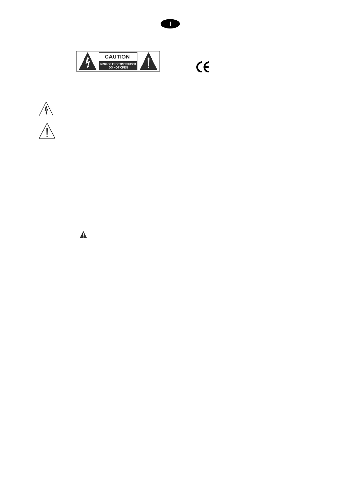
3. FUNZIONI E CONTROLLI PANNELLO FRONTALE
1. POWER
Interruttore principale
2. VOL
Volume del rispettivo canale microfonico
3. AF
I rispettivi led si accendono quando si sta parlando sulle rispettive basi
4. RF
I rispettivi led si accendono quando sul canale è in corso una trasmissione
5. Tasti di navigazione
Permettono di accedere alle impostazioni di ogni singolo canale
6. Display
Visualizza le informazioni relative ai rispettivi canali A e B / C e D
7. IR
Trasmettitore IR
8. Alette
Alette di fissaggio a Rack standard 19”
4. FUNZIONI E CONTROLLI PANNELLO POSTERIORE
fig.1
1. Connettore antenna C & D
Inserire l’antenna (in dotazione) operante in banda di frequenza C e D nel connettore a baionetta C&D ANT.
Posizionare l’antenna verticalmente
Nota: Non invertire le antenne in quanto la ricezione sarebbe sensibilmente ridotta.
fig.2
7
2. Connettore antenna A & B
Inserire l’antenna (in dotazione) operante in banda di frequenza A e B nel connettore a baionetta A&B ANT.
Posizionare l’antenna verticalmente
Nota: Non invertire le antenne in quanto la ricezione sarebbe sensibilmente ridotta.
3. MIX BAL OUT
Uscita di segnale mixata bilanciata (XLR3 Maschio) a livello linea.
(Collegare quest’uscita al mixer o all’amplificatore di sala).
4. MIX
Uscita di segnale mixata sbilanciata a livello linea.
(Collegare quest’uscita al mixer o all’amplificatore di sala).
5. ABCD
Uscite di tipo sbilanciato. Ad ogni uscita corrisponde esclusivamente il segnale proveniente dalla rispettiva
postazione microfonica.
6. Connettore alimentazione VDC
Collegare a questo connettore l’alimentatore AC/DC precedentemente collegato alla presa di rete 117230VAC.
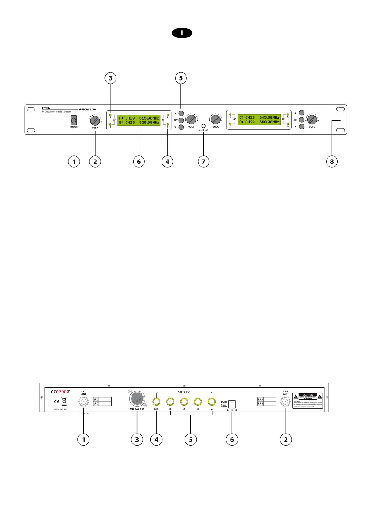
5. FUNZIONI E CONTROLLI CONSOLLE MICROFONICA WIRELESS BMW
1. Capsula microfonica
2. Indicatore luminoso di microfono attivo
Quando il microfono è attivo l’indicatore è acceso
fig.3
8

3. MIC ON/OFF
4. Power
5. IR
6. Low Bat
7. DISPLAY
Premendo questo tasto il microfono si accende e si è abilitati a parlare. Ad una successiva pressione il
microfono si spegne.
Il led è acceso quando il microfono è in trasmissione.
Porta infrarossi
Quando il led si accende sostituire o ricaricare le batterie.
Il display indica la frequenza di trasmissione della base microfonica e il livello di carica delle batterie.
La barra tratteggiata indica il livello di carica delle batterie, quando la barra si riduce a 3 elementi la batteria è
scarica.
8. VOL
Agire sul potenziometro per aumentare o diminuire il volume di uscita della base
9. H – R
RF Power
Regola la potenza di trasmissione della base microfonica. Per distanze (riferite all’unità ricevente) inferiori a
20 metri utilizzare l’impostazione L (Low Power), mentre per distanze superiori impostare il selettore su H
(Hight Power). Massima distanza operativa 50/60 metri.
Nota: l’impostazione del selettore influenza la durata delle batterie (8-9 h in Hi e 10-11 H in Lo)
10. Vano Batterie
11. Etichetta
Etichetta riportante la il canale e la banda operativa della base microfonica
6. COME UTILIZZARE IL SISTEMA
Collegare all’ingresso (fig.2, rif.6) l’alimentatore AC/DC precedentemente collegato alla presa di rete 117-
230VAC e accendere l’unità ricevente mediante il pulsante POWER (fig.1, rif.1).
Nota: Il sistema è già preimpostato in fabbrica e normalmente non necessita di essere reimpostato. Essendo tutti i
sistemi programmati sulle medesime frequenze, nel caso di utilizzo di più sistemi contemporaneamente è necessaria
una riprogrammazione.
9

Impostazione Canale A (Analogamente per il Canale C):
Premere due volte il tasto SET (fig.1, rif.5) e impostare la modalità del canale (CHANNEL/TUNE)mediante le
frecce su e giù (fig.1, rif.5) e premere SET per Confermare.
In modalità CHANNEL su ogni banda abbiamo a disposizione 60 canali spaziati di 250KHz.
In modalità TUNE su ogni banda abbiamo a disposizione 300 canali spaziati di 50KHz
La scelta della modalità dipende dall’occupazione in frequenza di ogni singolo paese e dalla presenza di possibili
interferenze..
Premere tre volte il tasto SET e impostare un livello di Squelch compreso tra -0,75dBm e -100dBm
Aumentando lo Squelch andiamo ad aumentare la soglia di apertura del canale RX, saranno ricevuti solo i segnali
superiori alla soglia.
Aumentare la soglia in presenza di disturbi esterni.
Impostazione manuale della frequenza di utilizzo:
Dopo aver impostato la modalità CHANNEL o TUNE premere una volta il tasto SET, la frequenza
operativa inizierà a lampeggiare, spostarsi con le frecce “giù” e “su” (fig.1, rif.5) e impostare la frequenza che
si intende utilizzare. Individuare tra le quattro basi in dotazione quella operante nello stesso range di
frequenze che si sta programmando (guardando le indicazioni riportate sul fondo della stessa (fig.3, rif.11) e
accenderla. Posizionare la base in modo che il trasmettitore IR (fig.1, rif.7) e il ricevitore IR (fig.3, rif.5) siano
uno di fronte all’altro e premere il tasto freccia “su” a questo punto a display comparirà la seguente
schermata
Quando la base microfonica sarà agganciata il rispettivo led RF (fig.1, rif.4) si accenderà e sul display della
base (fig.3, rif.7) sarà riportata la stessa frequenza del display. A questo punto la base della Banda A è
programmata e pronta all’uso.
Impostazione automatica della frequenza di utilizzo:
Dopo aver impostato la modalità CHANNEL o TUNE, Individuare tra le quattro basi in dotazione quella
operante nello stesso range di frequenze che si sta programmando (guardando le indicazioni riportate sul
fondo della stessa (fig.3, rif.11) ed accenderla.
Posizionare la base in modo che il trasmettitore IR (fig.1, rif.7) e il ricevitore IR (fig.3, rif.5) siano uno di fronte
all’altro, premere per due secondi il tasto freccia “su” (fig.1, rif.5) a questo punto a display comparirà la
seguente schermata
L’unità centrale farà una scansione delle frequenze libere ed assegnerà alla base microfonica la prima
frequenza non occupata.
Quando la base microfonica sarà agganciata il rispettivo led RF (fig.1, rif.4) si accenderà e sul display della
base (fig.3, rif.7) sarà riportata la stessa frequenza del display.
A questo punto la base della Banda A è programmata e pronta all’uso.
10

Impostazione Canale B (Analogamente per il Canale D):
Dopo aver premuto una volta il tasto SET (fig.1, rif.5) (la frequenza operativa inizierà a lampeggiare),
premere contemporaneamente SET e freccia “giù” (fig.1, rif.5) per passare alla Banda B.
Viceversa dalla Banda B: dopo aver premuto una volta il tasto SET (fig.1, rif.5) (la frequenza operativa inizierà
a lampeggiare), premere contemporaneamente SET e freccia “su” (fig.1, rif.5) per passare alla Banda A
A questo punto la frequenza operativa della Banda B inizierà a lampeggiare:
Ripetere le stesse operazioni descritte nella programmazione della Banda A facendo attenzione che la
trasmissione IR sarà avviata premendo una sola volta il tasto freccia “giù” (fig.1, rif.5) e che la scansione nella
programmazione automatica sarà avviata premendo per due seco ndi il tasto freccia “giù” (fig.1, rif.5)
Lista delle frequenze compatibili nei sistemi multicanale:
CANALE
KIT
KIT a
KIT b
7. RICARICA DELLE BATTERIE
Estrarre le 2 batterie dal vano batterie posto sul fondo della base (fig.3, rif.10).
Inserire le batterie nel carica batterie in dotazione.
Alimentare il carica-batterie.
Quando i led di segnalazione da rossi diventano verdi le batterie saranno cariche.
Tempo di ricarica circa 4-5 ore.
GP 1
GP 2
GP 3
GP 1
GP 2
GP 3
CH A
619.75 MHz
612.75 MHz 636.75 MHz 647.50 MHz 668.75 MHz
611.25 MHz
759.75 MHz 767.75 MHz 741.00 MHz 776.75 MHz
761.75 MHz 786.00 MHz 748.25 MHz 772.00 MHz
763.50 MHz 773.25 MHz 742.25 MHz 780.75 MHz
CH B
639.25 MHz 650.25 MHz 669.50 MHz
634.50 MHz 641.00 MHz 659.25 MHz
CH C
CH D
11

8. TIPO DI CONNESSIONI
Connessione di tipo bilanciata:
Connessione di tipo sbilanciata:
Connessione di tipo bilanciata con jack stereo
Connessione di tipo sbilanciata con jack stereo
Connessione Bilanciata su morsetto EUROBLOC
Connessione Sbilanciata su morsetto EUROBLOC
Connessione RCA
9. CONTENUTO DELLA CONFEZIONE
• Unità Centrale
• Quattro basi microfoniche
• Alimentatore AC/DC
• Caricabatteria esterno
• Cavi di collegamento
12

10. CARATTERISTICHE TECNICHE
MODEL DWS
System Four-channels receiver
Frequency band: UHF 610.00 ÷ 669.75MHz
Receiver type: PLL UHF Synthesized
Frequency response: 50Hz - 18KHz (-3dB)
T.H.D: < 0,5% 1KHZ
Modulation mode FM (F3E)
S/N Ratio > 105dB
Dynamic range >105dB
Audio output
Power Supply DC 12V-230/117Vca adaptor
Power consumption 8W
Dimensions (WxDxH) 483x21x44 mm – 1U Rack standard 19”
Weight 2,26 Kg
MODEL BMW
System Wireless Microphone Unit
Transmission mode PLL Multi-channels, up 300 frequency preset for each
Frequency band:
Frequency response: 50Hz - 18KHz (-3dB)
Modulation mode FM (F3E)
RF Output power Higth level:10 dBm
Tone Frequency 32 ÷ 51.2 KHz
Max deviaton +/-45KHz
Powe Supply
Microphone type Cardioid electrete condenser
Gooseneck length 42 mm
Dimensions (WxDxH) 134x156x480mm
Weight 0,6 Kg
Balanced: 600mV
Unbalanced: 2V
frequency band
a: UHF 610.00 ÷ 670.00MHz
b: UHF 730.00÷ 790.00MHz
Low level:5 dBm
Battery: 2xAA 1.2V-1200mAh (rechargeable batteries) or
2x AA 1.5 V
Il prodotto è conforme alla Direttiva 89/336/CEE (Compatibilità Elettromagnetica)
e successive modifiche 92/31/CEE e 93/68/CEE, secondo i seguenti standard:
EN 50082-1:1997, EN 55013:1990, EN 55020:1994
inoltre, è conforme alla Direttiva 73/23/CEE (Bassa Tensione)
e successive modifiche 93/68/CEE, secondo il seguente standard:
EN 60065:1998
13

AVVERTENZA
Questo apparecchio radio è inteso per uso professionale nell’ambito dell’intrattenimento e applicazioni similari.
Questo apparecchio potrebbe essere in grado di funzionare a frequenze non autorizzate nella regione in cui si trova
l’utente. Si consiglia di rivolgersi alle autorità competenti per ottenere le informazioni necessarie relative alle frequenze
autorizzate nella propria regione per i sistemi radiomicrofonici.
In alcuni casi potrebbe essere necessaria una licenza ministeriale per l’uso di questo apparecchio. Per i possibili
requisiti rivolgersi alle autorità competenti.
L’utente si assume l’esclusiva responsabilità per l’acquisizione della licenza delle attrezzature senza fili e la
licenziabilità dipende dalla classificazione e dall’applicazione dell’utente e dalla frequenza selezionata.
Ai sensi del D. Lgs. 269/2001 art.6 comma 3
Il prodotto è conforme alla Direttiva 89/336/CEE (Compatibilità Elettromagnetica) e successive modifiche 92/31/CEE e
93/68/CEE.
Inoltre, è conforme alla Direttiva 73/23/CEE (Bassa Tensione) e successive modifiche 93/68/CEE.
La Proel SpA persegue una politica di costante ricerca e sviluppo, di conseguenza si riserva il diritto di apportare miglioramenti ai prodotti esistenti,
senza preavviso e in qualunque momento. REV. 00 29/13
14

INDICE
1. IMPORTANT SAFETY INSTRUCTIONS ................................................................................ 16
2. DESCRIPTION ....................................................................................................................... 18
4. FUNCTIONS AND REAR PANEL CONTROLS ..................................................................... 19
5. FUNCTIONES AND CONTROLS WIRELESS MIROPHONE CONSOLE BMW ................... 20
6. HOW TO USE THE SYSTEM ................................................................................................. 21
7. BATTERY RECHARGE PROCESS ....................................................................................... 23
8. TYPE OF CONNECTION ....................................................................................................... 24
9. PACKAGE CONTENT............................................................................................................ 25
10. TECHNICAL FEATURES ....................................................................................................... 25
15

1. IMPORTANT SAFETY INSTRUCTIONS
CAUTION: To reduce the risk of electric shock do not remove cover (or back panel). No user serviceable parts inside. Refer servicing to
WARNING: To reduce the risk of fire or electric shock, do not expose this apparatus to rain or moisture.
This symbol is intended to alert the user of the presence of uninsulated dange rous voltage within the product enclos ure that ma y
This symbol is intended to alert the user of the presence of important operating and maintenance (servicing) instruction in the
INSTRUCTIONS:
All safety and operating instructions should be read before the product is operated.
Retain these instructions:
All safety and operating instructions should be retained for future reference.
This owner’s manual should be considered as a part of the product, it must accompany it at all times, and it needs to be delivered to the new user
when this product is sold. In this way the new owner will be aware of all the installation, operating and safety instructions.
Heed all warnings:
All warnings on the product and in owner’s manual should be adhered to.
Heed all warnings.
Follow all instructions:
All operating and user’s instructions must be followed.
qualified personnel only.
be of sufficient magnitude to constitute a risk of electric shock to persons.
literature accompanying the appliance. Please carefully read the owner’s manual.
Sentences preceded by symbol contain important safety instruction. Please read it carefully.
DETAILED SAFETY INSTRUCTIONS.
Water and moisture:
This apparatus should not be used near water (i.e. bathtub, kitchen sink, swimming pools, etc.)
Ventilation:
This apparatus should be placed in a position that doesn’t interfere with its correct ventilation. This unit, for example, should not be placed on a
bed, sofa cover o similar surfaces that could cover ventilation openings, or placed in a built-in installation, such a bookcase or a cabinet that
could block air flow trough ventilation openings.
Heat:
This apparatus should be placed away from sources of heat, like radiators, heat registers, stoves or other products (including amplifiers) that
produce heat.
Power sources:
• This apparatus should only be connected to a power source of type specified in this owner’s manual or on the unit.
• If the supplied AC power cable plug is different from wall socket, please contact an electrician to change the AC power plug.
Grounding or Polarization:
• All precautions must be observed in order to avoid defeating grounding or polarization.
• Unit metal parts are grounded through the AC power cord.
• If the AC power outlet doesn’t have grounding, consult an electrician for outlet grounding.
Power cable protection:
The power cable should be routed in such a way that it will not be walked on or pinched by items placed upon or against it, paying particular
attention to cables at their connections, receptacles and wall outlet.
Cleaning:
• You can clean the exterior of the unit with compressed air or a damp cloth.
• Don’t clean the unit using solvents like trichloroethylene, thinners, alcohol, or other volatile or flammable fluids.
Non use periods:
The unit AC power cable should be unplugged from the outlet if it’s unused for long periods.
16

Objects or liquid entry into the unit:
Be careful that no objects fall into the unit or that no liquid is spilled inside the unit through ventilation openings.
Safe power line use:
• Hold the plug and the wall outlet firmly while disconnecting the unit from AC power.
• When the unit will not be used for a long period of time, please unplug the power cord from AC power outlet.
• To avoid power cable damage, don’t strain the AC power cable and don’t bundle it.
• In order to avoid damage to the unit's power cable, be sure that the power cable is not walked on or pinched by heavy objects.
Unit relocation:
Before relocating the unit, please control the unit is turned off. The power cord must be unplugged from the wall outlet, and all the co nnecting
cables should be disconnected as well.
Do not open this unit:
Do not attempt to open or repair this unit yourself. For any problem not described in this owner’s manual, please refer to qualified personnel only
or consult us or your National Distributor. Any improper operation could result in fire or electric shock.
Damages requiring services:
• Do not attempt to perform operations not described in this user’s manual.
• In the following cases please refer to an authorized service center or skilled personnel:
- When the unit works improperly or it doesn’t work at all.
- If power cord or plug is damaged.
- If liquid has spilled, or objects have fallen into the unit.
- The unit has been exposed to rain.
- The unit doesn’t operate normally or exhibits a marked change in performance.
- If the product has been dropped or has been damaged in any way.
Maintenance:
The user shouldn’t attempt maintenance not described in this user’s manual. All maintenance should be performed by qualified personnel only.
IMPORTANT SAFETY INSTRUCTIONS:
• Install this unit following owner’s manual instructions.
• Do not install, connect or disconnect power supply when the unit is powered, otherwise there is a high risk of electric shock.
• Do not open the unit, there are no user serviceable parts inside.
• If you detect a particular smell from the unit, please immediately turn it off and disconnect the AC po wer cord.
• Don’t block the unit's ventilation openings.
• Avoid using this unit in overload for a long period.
• Don’t force commands (switches, controls, etc.)
• To obtain good speaker wire contact, please tighten the screw terminals firmly.
• For safety reasons, do not defeat the grounding connection. Grounding is for user safety.
• Use only connectors and accessories suggested by the manufacturer. .
• This unit should be fitted in an equipment rack (see INSTALLAT ION) and kept far from:
¾ Wet places
¾ Direct exposure to heat sources (like sun light)
¾ Improperly ventilated places
• Disconnect the power cord during storms or when the unit is not in use.
• In order to prevent fire and reduce risk of electric shock, it is necessary to keep the unit far from dripping water. Plea se don’t put cups ,
vases or other object containing liquids over the unit. In case of interference from source signal, THD value will raise over 10%. Don’t place
this unit in a bookshelf or in other enclosed spaces.
• PROEL S.P.A. is not responsible for any damage that occurs due to a incorrect installation of the unit.
17

Thank you for choosing this Proel product and for trusting our brand, which strives to be synonymous with
professionalism, precision, high quality and reliability. All of our products comply with EC regulations regarding audio
equipment for continuous use.
2. DESCRIPTION
Wireless conference system is composed by a receiver unit referred DWS, four wireless stands BMW and a
battery charger.
The system is UHF PLL and is equipped with an anti- interferences system and TONE LOCK.
2 Frequencies range are available within the following bands : a: 610÷ 670 MHz and b:730÷ 790MHz
For each frequency range 3 receivers units for a maximum of 12 microphone units. When both range of
frequencies are used, we can obtain up to 6 receivers units (3 from one frequency range and 3 from the other ) for a
maximum of 24 microphone units (12 with set up on the frequency range of the type a and 12 of the type b ) working
contemporaneously.
Each central unit features 4 channels:
Range a:
Channel A: band 610.00 ÷ 624.75 MHz
Channel B: band 625.00 ÷ 639.75 MHz
Channel C: band 640.00 ÷ 654.75 MHz
Channel D: band 655.00 ÷ 669.75 MHz
Range b:
Channel A: band 730.00-744.75MHz
Channel B: band 745.00-759.75MHz
Channel C: band 760.00-774.75MHz
Channel D: band 775.00-789.75MHz
Each stand BMW is operating exclusively on one of the fourth frequency ranges ( you can easily read on each stand
rear back (fig.3, ref.11). The stand power supply is effected through a couple of rechargeable AA 1,2V 1200mA
batteries or in alternative a couple of normal disposable AA,1,5 V batteries.
Note: the batteries timing is 8-9 h when the Tx power selector is on Hi position or 10-11 h when the selector is on Lo
position.
Main features:
• Dual display
• Keys for navigation
• Single level control for each stand
• Infrared technology for operating frequency set up
• Balanced output and mixed unbalanced output
• Single output for each channel
• Channel or Tuning frequency mode
• Squelch control separately and for each single stand
• Wireless console with display and light ring to indicate operating condition
• Range 50/60 mt
• Case in metal one unit 19” rack standard
Product complies with CE regulations
18

3. FUNCTIONS AND FRONT PANNEL CONTROLS
1. POWER
Main Switch
2. VOL
Microphone channel volume control
3. AF
When the stands are in use, the corresponding Led is ON.
4. RF
When set on channel, there is one transmission active and the corresponding Led is ON
5. Navigation keys
Allow to access to the single channel setting
6. Display
Displays the information of channel A and B / C and D
7. IR
IR Transmitter
8. Brackets
Brackets for 19” Rack standard fixing purposes
4. FUNCTIONS AND REAR PANEL CONTROLS
fig.1
1. Antenna C & D connector
Insert the antenna ( supplied with the package) operating in frequency C and D into bayonet connector C&D
ANT. Set the antenna vertically.
fig.2
19

Note: do not invert the antenna in order to avoid reducing substantially the reception quality.
2. Antenna A & B connector
Insert antenna ( supplied with the package ) operating frequency A and B into the bayonet connector A &B
ANT. Set vertically the antenna.
Note: do not invert the Antenna in order to avoid reducing substantially the reception quality.
3. MIX BAL OUT
Balance mixed signal output (XLR3 Male ) line level.
(Connect this output to the eventual available mixer or amplifier .
4. MIX
Unbalanced and mixed output line level.
(Connect this output to the eventual available mixer or amplifier).
5. ABCD
Unbalanced output. to each output does correspond exclusively the respective microphone stand signal.
6. VDC power supply connector
Connect this connector to AC/DC power supply prior connect to the main power supply 117-230VAC.
5. FUNCTIONES AND CONTROLS WIRELESS MIROPHONE CONSOLE BMW
1. Microphone capsule
2. Indicator light on active microphone
fig.3
20

When the microphone is ON this indicator light is ON.
3. MIC ON/OFF
4. Power
5. IR
6. Low Bat
7. DISPLAY
Pressing this key the microphone status is ON and the speech is enabled, the following key press switches
off the microphone.
led is ON when the microphone is operating.
Infrared (input) door.
When Led is ON, replace or recharge the battery.
Display states the microphone stand frequency of transmission and the level of the battery charge.
Dashes line drawing inform on the battery charge level , When the dashes are just 3, the battery is
discharged.
8. VOL
Microphone stand volume output level control.
9. H - R
RF Power
For microphone stand transmission power set up. When the distance ( with reference to the receiver unit) is
less than 20 meters use L (Low Power) set up, while for distances above 20 meters set the selector on
H(High Power). The maximum operating distance 50/60 meters.
Note: the selector setting influences the battery charges duration (8-9 h at Hi and 10-11 H at Lo)
10. Battery compartment
11. Label
Label reports the microphone stand channel and operating band.
6. HOW TO USE THE SYSTEM
Connect to the input (fig.2, ref.6) AC/DC power supply. Prior connect to the main power supply 117-230VAC
and switch On the receiver Unit through the POWER key (fig.1, ref.1).
Note: the system features the factory setting and does not need any new setting up. The factory system set up
program is done on the same frequency. In case of contemporaneous multi system use, the reprogramming is
necessary.
21

Channel A set up (Similarly for Channel C):
Press 2 times SET key (fig.1, ref.5) and set channel mode (CHANNEL/TUNE) through Arrow on “down” (fig.1,
ref.5) and press SET to confirm.
CHANNEL MODE: for each band 60 channels 250 Khz spaced are available.
TUNE MODE: for each band , 300 channels 50Khz spaced are available
The selection MODE does depend on the frequency occupancy status for each country and possible interferences
presence.
Press 3 times SET key and set Squelch level within -0,75dBm e -100dBm
Increasing the Squelch level we will increase the channel RX opening level therefore only signal above will be
received.
Increase such level in case of external interferences presence.
FREQUENCY OF USE AND MANUAL SET UP:
After having set CHANNEL or TUNE Mode press one time SET key, the operating frequency will start
lighting up, shift with the arrow “down” and “Up” (fig.1, ref.5) and set the frequency you want to use. Select one
stand amongst the four microphone stands operating in the same frequency range planned to be programmed
reading the indications reported on the back rear of this stand (fig.3, ref.11) and switch on.
Position the stand to have the transmitter IR (fig.1, ref.7) and the receiver IR (fig.3, ref.5) are one front of the
other and press the Arrow “UP”, on the display will appear the following frame
When the microphone stand is coupled, the respective RF Led (fig.1, ref.4) will switch on and on the stand
display (fig.3, rif.7) the coupling frequency will appear. The stand of the Band A is programmed and ready to be
used.
AUTOMATIC SET UP OF THE FREQUENCY OF USE:
After having set CHANNEL OR TUNE Mode. Select one microphone stand within the four available
microphone stands operating in the same frequency planned to be programmed (reading the indications reported
on the rear back of this stand (fig.3, ref.11) and switch on.
Position the stand in order to have IR transmitter (fig.1, ref.7) and IR receiver IR (fig.3, ref.5) are the front one of
the other , press for 2 seconds Arrow key “UP” (fig.1, ref.5) . At this point on the display will appear the following
frame
The main central unit will scan the free frequencies and will appoint to the microphone stand the first free
available frequency .
When the microphone stand will be coupled and the relevant Led RF (fig.1, ref.4) will switch on, the same
frequency will appear on the microphone stand display.
At this point the stand of the Band A is programmed and ready for use.
22

Channel B setting (Similarly for Channel D):
After having pressed SET key (fig.1, ref.5) ( the operating frequency will start lighting up ), press
contemporaneously SET and arrow “down” (fig.1, ref.5) to pass to band B.
Vice versa from band B: after having pressed one time SET key (fig.1, ref.5) ( the operating frequency will start
lighting up), press contemporaneously SET and Arrow “up” (fig.1, ref.5) to pass to Band A
At this point the operating frequency of band B will start lighting up:
Repeat the same operations as here above described in order to program Band A. Make sure that IR
transmission process will start pressing one time Arrow Key “down” (fig.1, ref.5) and the automatic programming
process scan will start pressing for 2 seconds Arrow key “down” (fig.1, ref.5)
List of compatible frequencies for multi-channel systems:
CANALE
KIT
KIT a
KIT b
7. BATTERY RECHARGE PROCESS
Pull out the 2 batteries from the battery compartment set in the rear side of the microphone stand (fig.3, ref.10).
Insert the battery into the battery charger contained into the supply package.
Power on the battery charger.
When the red LED indicator turns green the batteries are fully charged .
Charging time is about 4-5 hours.
GP 1
GP 2
GP 3
GP 1
GP 2
GP 3
CH A
619.75 MHz
612.75 MHz 636.75 MHz 647.50 MHz 668.75 MHz
611.25 MHz
759.75 MHz 767.75 MHz 741.00 MHz 776.75 MHz
761.75 MHz 786.00 MHz 748.25 MHz 772.00 MHz
763.50 MHz 773.25 MHz 742.25 MHz 780.75 MHz
CH B
639.25 MHz 650.25 MHz 669.50 MHz
634.50 MHz 641.00 MHz 659.25 MHz
CH C
CH D
23

8. TYPE OF CONNECTION
Balanced connection:
Unbalanced connection:
Balanced connection with TRS jack
Unbalanced connection with TRS jack
Balanced connection on EUROBLOC connector
Unbalanced connection on EUROBLOC connector
RCA Connection
24

9. PACKAGE CONTENT
• Main central unit
• Four microphone stand
• AC/DC power supply
• External battery charger
• Connection cables
10. TECHNICAL FEATURES
MODEL DWS
System Four-channels receiver
Frequency band: UHF 610.00 ÷ 669.75MHz
Receiver type: PLL UHF Synthesized
Frequency response: 50Hz - 18KHz (-3dB)
T.H.D: < 0,5% 1KHZ
Modulation mode FM (F3E)
S/N Ratio > 105dB
Dynamic range >105dB
Audio output
Power Supply DC 12V-230/117Vca adaptor
Power consumption 8W
Dimensions (WxDxH) 483x21x44 mm – 1U Rack standard 19”
Weight 2,26 Kg
MODEL BMW
System Wireless Microphone Unit
Transmission mode PLL Multi-channels, up 300 frequency preset for each
Frequency band:
Frequency response: 50Hz - 18KHz (-3dB)
Modulation mode FM (F3E)
RF Output power Higth level:10 dBm
Tone Frequency 32 ÷ 51.2 KHz
Max deviaton +/-45KHz
Powe Supply
Microphone type Cardioid electrete condenser
Gooseneck length 42 mm
Dimensions (WxDxH) 134x156x480mm
Weight 0,6 Kg
Balanced: 600mV
Unbalanced: 2V
frequency band
a: UHF 610.00 ÷ 670.00MHz
b: UHF 730.00÷ 790.00MHz
Low level:5 dBm
Battery: 2xAA 1.2V-1200mAh (rechargeable batteries) or
2x AA 1.5 V
25

WARNING
LICENSING INFORMATION
Changes or modifications not expressly approved by Proel S.p.A. could void your authority to operate the equipment.
Licensing of wireless microphone equipment is the user’s responsibility, and licensability depends on the user’s
classification and application, and on the selected frequency. Proel strongly urges the user to contact the appropriate
telecommunications authority concerning proper licensing, and before choosin g and ordering frequencies.
IMPORTANT!
This equipment may be capable of operating on some frequencies not authorized in your region. Please contact your
national authority to obtain information on authorized frequencies for wireless microphone products in your region.
The product is in compliance with Directive 89/336/EEC (Electromagnetic Compatibility) and following modifications
92/31/EEC and 93/68/EEC. It is also in compliance with Directive 73/23/EEC (Low Voltage) and following modifications
93/68/EEC.
PROEL S.p.A hereby, declares that this wireless microphone system complies with the essential requirements and
other relevant provisions of
Directive 1999/5/EC.
Consult local or national radio spectrum authorities for information on possible restrictions or necessary authorizations
before using this Short Range Device.
Proel SpA maintains a policy of constant research and development, therefore we reserve the right to apply improvements to existing equipment
without prior notice. REV. 00 29/13
26

27

PROEL S.p.A.
(World Headquarters - Factory)
Via alla Ruenia 37/43
64027 Sant’Omero (Te) – Italy
Tel: +39 0861 81241
Fax: +39 0861 887862
info@proel.com
E-mail:
www.proel.com
28
 Loading...