

Page 1

SOUND REINFORCEMENT
DSO26
DIGITAL SYSTEM OPTIMIZER
’
www.proelgroup.com MADE IN EUROPE
Page 2
DSO26 User Manual
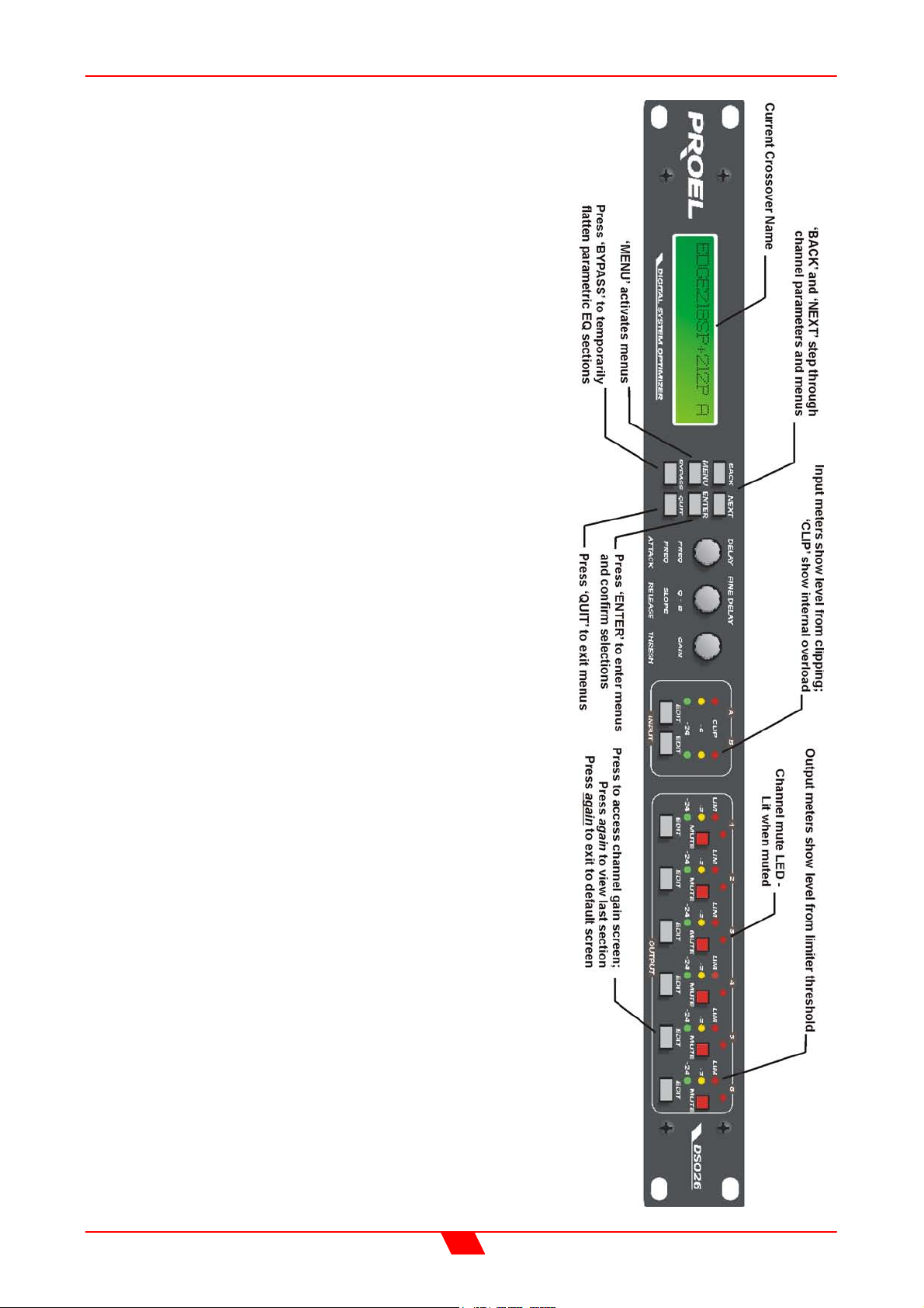
DSO26 Quick Reference
Accessing channels: press channel’s GAIN button.
First press accesses that channel’s gain. To scroll
through a channels parameters, use the BACK and NEXT
keys. Second press accesses last viewed parameter.
Third press will drop back to the default screen.
Accessing menus: press the MENU key. Use the BACK
and NEXT keys to select the sub-menu required, and
enter using the ENTER key. This applies to all levels of
menu. ENTER always confirms selections.
The Menus and their Contents
Input Setup Sub-menu: Used for ganging input gain and
base delays.
X-over Sub-menu: Used for storage and recall of
crossovers, including format, output EQ, output delay,
output gain, and limiter settings. Also used for design of
new crossovers.
Security Sub-menu: Used for locking various features of
the units, using a four digit code.
System Sub-menu: Used to view the units status, and
select various global options such as parametric EQ ‘Q’
or bandwidth units, and output meter monitoring point
(pre or post mute).
Notes
The crossover or output settings are stored and recalled
independently (using store/recall a X-Over) from the input
settings (using store/recall input memory).
The output meters show level, in dB, from the limiter
threshold. The input meters show level, in dB, from input
clip.
The high and low-pass filters are defined independently
on each channel.
To access the limiter attack and release parameters,
select ‘Auto Limiter TC’ No, when designing a crossover.
To swap parametric filter units between bandwidth (‘BW’)
and ‘Q’, enter the ‘System sub-menu, select ‘Filter Q or
BW’, and select required readout units.
2
Page 3

DSO26 User Manual
CONTENTS
DSO26 QUICK REFERENCE .............................................................................................2
The Menus and their Contents .......................................................................................................................... 2
Notes.................................................................................................................................................................. 2
CONTENTS .........................................................................................................................3
IMPORTANT SAFETY INFORMATION ..............................................................................6
THANKS..............................................................................................................................7
UNPACKING THE DSO26 ..................................................................................................7
INTRODUCTION .................................................................................................................8
Features............................................................................................................................................................. 8
FRONT PANEL FAMILIARISATION...................................................................................9
REAR PANEL CONNECTIONS ........................................................................................10
OPERATING THE DSO26.................................................................................................11
Preliminary Set-up ........................................................................................................................................... 11
DSO26 CONFIGURATIONS .............................................................................................12
Introduction ...................................................................................................................................................... 12
2 x 2 way with Mono Sum ................................................................................................................................ 12
2 x 3 way.......................................................................................................................................................... 12
4 way + 2 ......................................................................................................................................................... 14
5 way + 1 ......................................................................................................................................................... 15
6 way................................................................................................................................................................ 16
SCREEN LAYOUTS OVERVIEW .....................................................................................17
AUDIO FUNCTION SCREENS .........................................................................................18
Gain Screen ..................................................................................................................................................... 18
Polarity Screen ................................................................................................................................................ 19
Delay Screen ................................................................................................................................................... 20
High and Low Pass Filter Screens .................................................................................................................. 21
Parametric Equaliser Screen ........................................................................................................................... 22
Limiter Screen.................................................................................................................................................. 23
3
Page 4

DSO26 User Manual
MENU SELECTION...........................................................................................................24
INPUT SETUP SUB-MENU...............................................................................................25
Gang Inputs ..................................................................................................................................................... 25
X-OVER SUB-MENU.........................................................................................................26
Load a Xover ................................................................................................................................................... 26
Design a Xover ................................................................................................................................................ 26
Store a Xover................................................................................................................................................... 26
Erase a Xover Mem ......................................................................................................................................... 26
SECURITY SUB-MENU ....................................................................................................27
User Specific.................................................................................................................................................... 27
Xover Only ....................................................................................................................................................... 27
Xover + Trim .................................................................................................................................................... 27
Xover + Trim + Mute ........................................................................................................................................ 27
Changes Only .................................................................................................................................................. 27
Changes + View............................................................................................................................................... 27
Changes + Mutes ............................................................................................................................................ 27
EVERYTHING ................................................................................................................................................. 27
Entering the Password to Complete the Locking Operation............................................................................ 28
SYSTEM SUB-MENU........................................................................................................29
System Status.................................................................................................................................................. 29
LCD Contrast ................................................................................................................................................... 29
LED Brightness ................................................................................................................................................ 29
Temperature Alarm.......................................................................................................................................... 29
Wake-up Time ................................................................................................................................................. 29
Output Meters .................................................................................................................................................. 29
Filter Q or BW .................................................................................................................................................. 29
Delay Time/Distance........................................................................................................................................ 29
INTERFACE SUB-MENU..................................................................................................30
Interface Setup ................................................................................................................................................ 30
AES / EBU SUB-MENU.....................................................................................................31
Routing Options ............................................................................................................................................... 31
AES Diagnostics .............................................................................................................................................. 31
AES / EBU Connections .................................................................................................................................. 31
OPERATING NOTES ........................................................................................................32
Operating Level ............................................................................................................................................... 32
Grounding ........................................................................................................................................................ 32
4
Page 5

DSO26 User Manual
Crossover Filter Slopes ................................................................................................................................... 32
Time Alignment................................................................................................................................................ 33
Output Limiters ................................................................................................................................................ 34
Setting Accurate Limiter Thresholds................................................................................................................ 35
FACTORY PRESETS........................................................................................................37
EDGE presets.................................................................................................................................................. 37
TFL presets...................................................................................................................................................... 39
Voltage gain of TFL amplifiers ......................................................................................................................... 42
SPECIFICATIONS.............................................................................................................43
WARRANTY......................................................................................................................44
OPTIONS AND ACCESSORIES.......................................................................................44
APPENDICES ...................................................................................................................45
Appendix 1: Limiter threshold in dB to Vrms lookup table.............................................................................. 45
Appendix 2: Default X-over settings and names for all formats. ..................................................................... 46
Appendix 3: Equalisation Curves.................................................................................................................... 47
5
Page 6
DSO26 User Manual
An example of this equipment has been tested and found to comply with the
following European and international Standards for Electromagnetic
Compatibility and Electrical Safety:
Radiated Emissions (EU): EN55013-1 (1996)
RF Immunity (EU): EN55103-2 (1996) RF Immunity, ESD, Burst Transient, Surge, Dips &
Dwells
Electrical Safety (EU): EN60065 (1993)
Important Safety Information
Do not remove Covers.
No user serviceable parts inside, refer servicing to qualified service personnel.
This equipment must be earthed.
CAUTION
RISK OF ELECTRIC SHOCK
DO NOT OPEN
DO NOT EXPOSE TO RAIN OR MOISTURE
It should not be necessary to remove any protective earth or signal cable shield
connections.
Do not defeat the purpose of the polarized or grounding-type plug. A polarized plug has
two blades with one wider than the other. A grounding type plug has two blades and a third
grounding prong. The wider blade and the third prong are provided for your safety. When
the provided plug does not fit into your outlet, consult an electrician for replacement of the
obsolete outlet.
Only use this equipment with an appropriate mains cord.
In the USA the cord should comply with the requirements contained in the Standard for
Cord Sets and Power Supply Cords, UL 817, be marked VW-1, and have an ampacity
rating not less than the marked rating of the apparatus.
6
Page 7

DSO26 User Manual
THANKS
Thank you for choosing the DSO26 for your application. Please spend a little time reading
through this manual, so that you obtain the best possible performance from the unit.
All our products are carefully designed and engineered for cutting-edge performance and
world-class reliability. If you would like further information about this or any other product,
please contact us.
We look forward to hearing from you in the near future.
UNPACKING THE DSO26
After unpacking the unit, please check it carefully for any damage. If any is found,
immediately notify the carrier concerned - you, the consignee, must instigate any claim.
Please retain all packaging in case of future re-shipment.
7
Page 8

DSO26 User Manual
INTRODUCTION
The DSO26 is a powerful DSP based audio processor, ideally suited for live sound
applications, where it combines the functions of a multitude of conventional products in a
compact 1U unit. To achieve this, the DSO26 has two inputs and six outputs which can be
configured in five basic crossover modes – 3 x 2 way; 2 x 3 way; 4 way; 5 way; and 6 way.
Each input has a gain control, and variable base delay. Each output has a gain control,
variable delay, high and low pass filters, five bands of fully parametric equalisation, polarity
switching and, additionally, a fully featured limiter.
Multi-part security lock-out is available for all controls.
The DSO26 is also available with optional AES/EBU digital inputs and outputs.
It has been designed for quick, intuitive adjustment through the use of multiple controls to
provide an easy-to-use interface.
Features
Superb audio quality – carefully optimised double precision signal processing
coupled with a 40-bit internal data path ensures a dynamic range in excess of
110dB. The high sampling rate means minimal filtering providing exceptional sonic
purity.
A flexible 2-input/6-output multi-mode format caters for any crossover configuration,
regardless of scale.
A total of 30 parametric equalisation bands are available, each providing +15 to –
30dB of gain at centre frequencies between 20Hz and 20kHz, with a wide range of
‘Q’s available between 0.4 to 128. All parameters feature fine resolution with 1/36
octave frequency steps, 0.1dB gain increments, and 100 ‘Q’ settings. Any
parametric section can also be set to operate as a high or low shelving filter.
Each output features a high performance limiter, provided with complete control
over attack, release and threshold parameters. To aid set-up, the output meters
show headroom to the limiter threshold, and use time constants that track those of
the limiter to display precise power usage.
Each output features variable high and low pass filters, with a choice of 12, 18 or
24dB/Octave roll-off, and Butterworth, Bessel or Linkwitz-Riley responses.
Independent control of each high and low pass filter allows asymmetric crossover
bands to be created.
Delay of up to 650mS may be independently set for each output, with an
exceptionally fine minimum increment of 2.6µS.
Three velocity-sensitive encoders provide a familiar and intuitive control format with
all filter information displayed simultaneously on a backlit LCD screen.
AES/EBU Digital input and output interfaces are available as an option.
Input and output balancing transformers are also available as an option.
8
Page 9
DSO26 User Manual
FRONT PANEL FAMILIARISATION
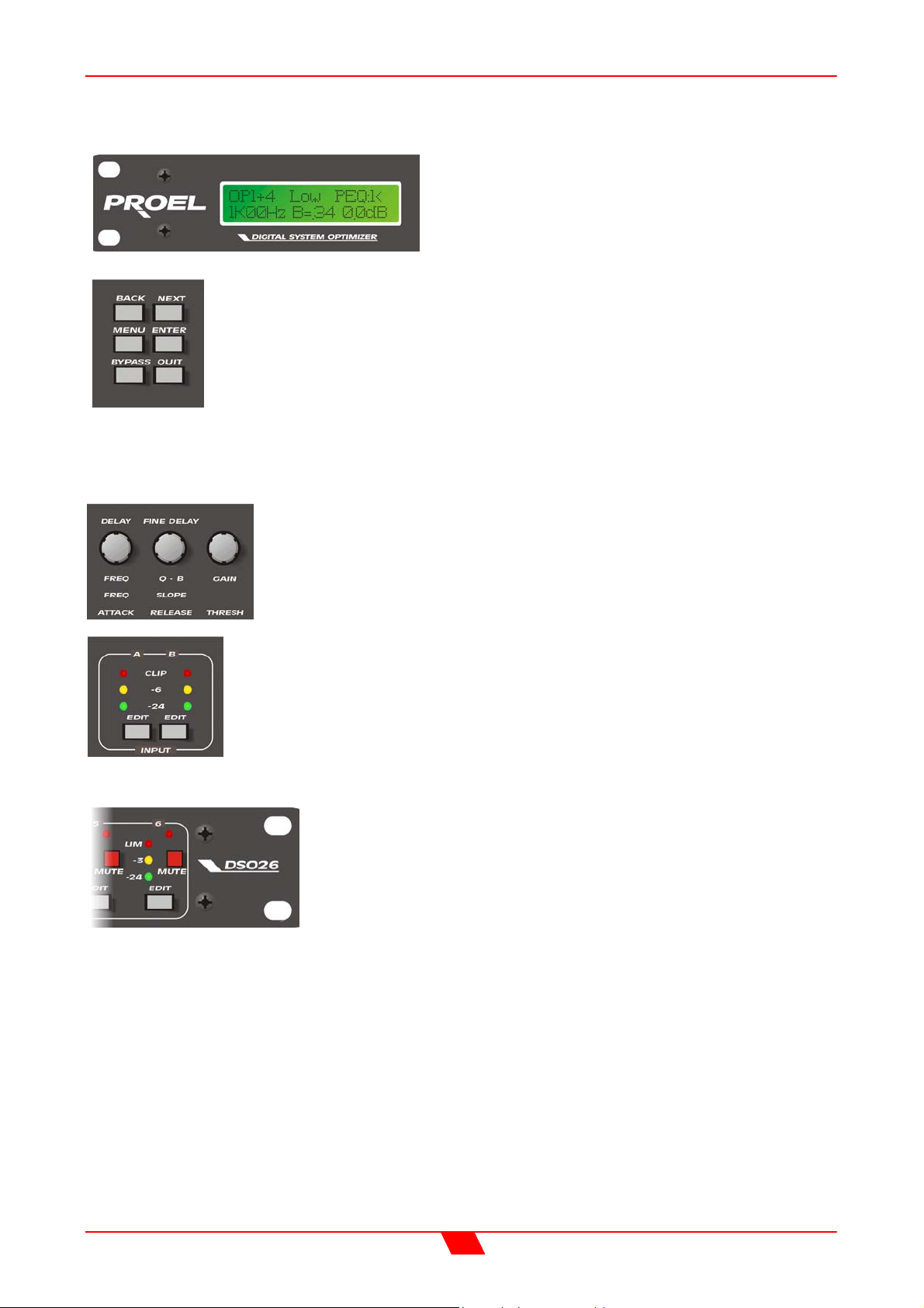
LCD Screen: shows menu options, channel
information, and various parameters as they are
adjusted.
Next Key : moves forwards through the list of available parameters.
Back Key : moves back through the list of available parameters.
Menu Key : activates the main menu. A second press selects the last
menu edited. Selection of different menus may be accomplished using the
Back and Next keys, or by turning the ‘Freq’ encoder.
Enter Key : enters the chosen menu and confirms choices.
Bypass Key : bypasses the currently selected parametric EQ section.
Note that, for safety reasons, the high and low pass filters cannot be bypassed using this
key.
Quit Key : exits the menu.
Encoders : three velocity sensitive controls allow the relative
parameter displayed on the LCD screen to be adjusted.
Gain Keys : one for each input and output, allowing instant access to
the gain screen for the selected channel.
Input Meters : display available headroom below clipping. The yellow
‘-6dB’ LED illuminates at 6dB below the actual clipping point of the input
section. The red ‘Clip’ LED shows digital overflow and can therefore
illuminate independently of the rest of the meter.
Output Meters: display headroom below limiting. The yellow
LED illuminates 3dB below limiting for that channel. The red
LED indicates the onset of limiting.
Mute Keys: mutes the appropriate channel, and illuminates
the associated LED.
9
Page 10
DSO26 User Manual
REAR PANEL CONNECTIONS
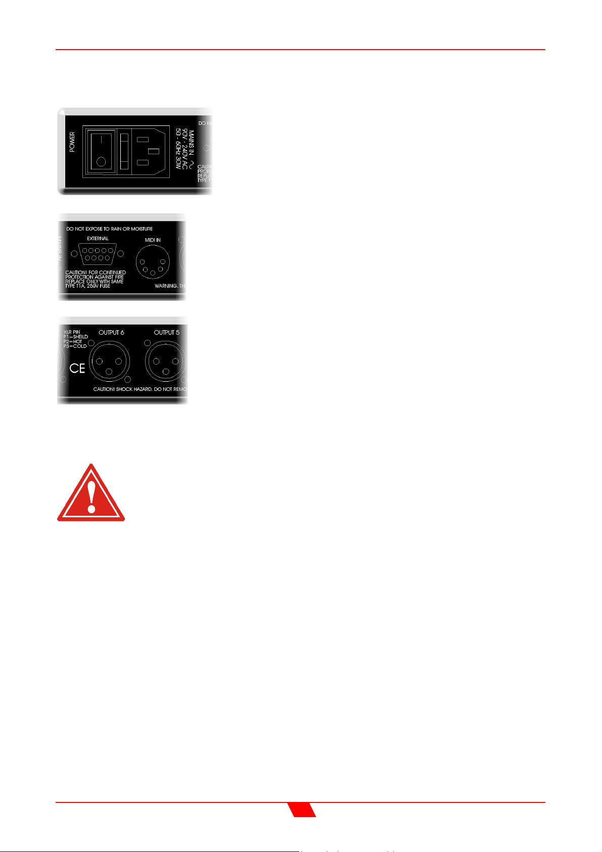
Power Switch: turns the units mains supply off and on.
Mains Fuse: located in a finger-proof holder adjacent to
the mains inlet. A spare fuse is also located in this holder.
Mains Inlet: connected via a standard IEC socket.
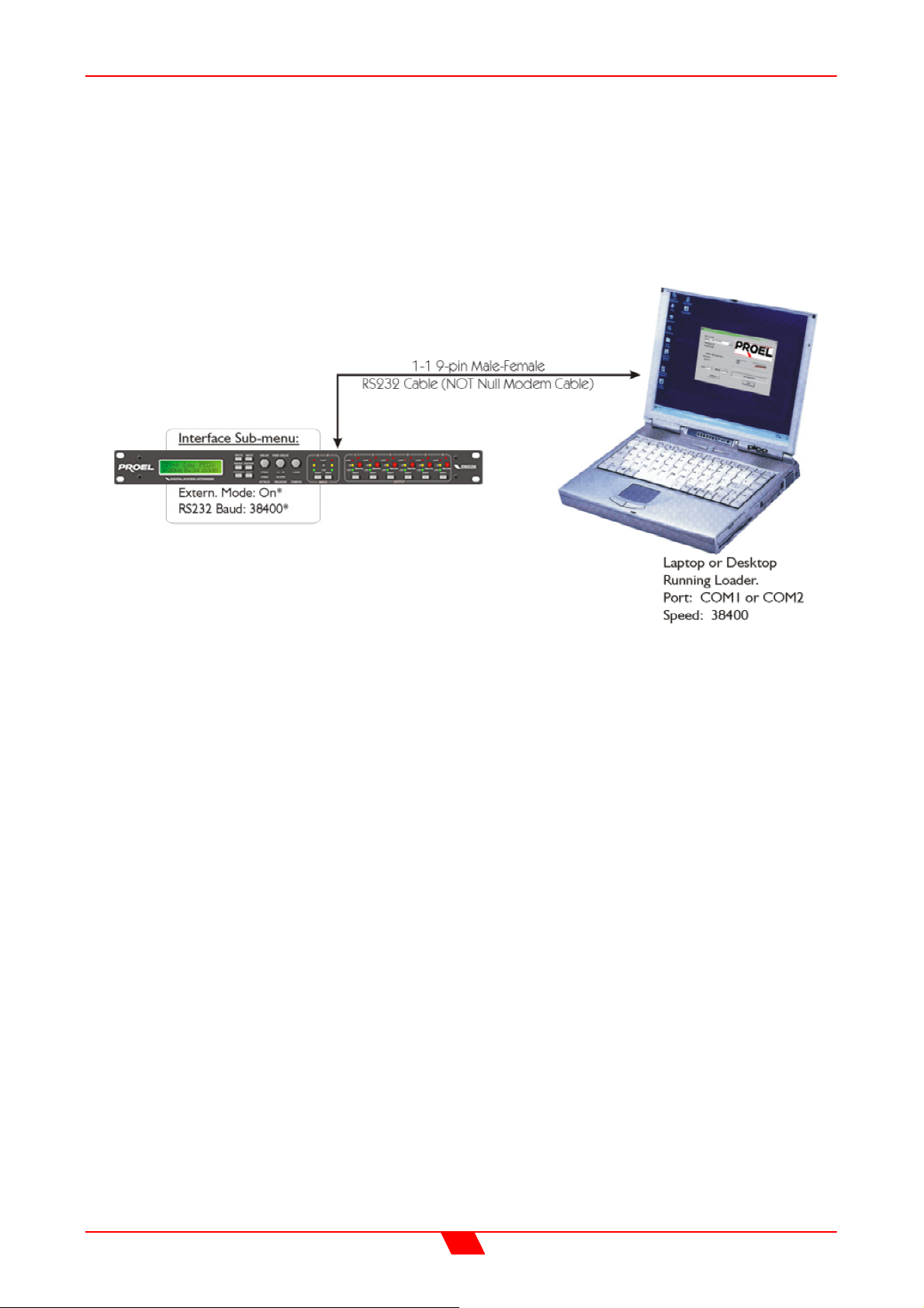
External: RS232 standard via a 9 pin D-type connector, for
connection to a PC, enabling the uploading of new software to
the unit.
Audio In-Out: 3 pin XLR sockets are provided for each
channel. All are fully balanced, pin 2 hot, 3 cold, 1 screen.
Always replace the fuse with the correct type and rating as shown on the
rear panel legend.
10
Page 11

DSO26 User Manual
OPERATING THE DSO26
If you want to use the Proel EDGE and TFL presets you can skip this section and jump
directly to ‘Load a Xover’ page 26.
Preliminary Set-up
The procedure below should be followed when first installing a DSO26.
Design your crossover! To do this, press MENU, and use the BACK or NEXT key to
select ‘X-over sub-menu’ and then press ENTER. Use the BACK or NEXT key to
select ‘Design a X-over’ and then press ENTER. Finally, use the BACK or NEXT
key to select the desired configuration and follow the set-up wizard to finalise your
design.
Note that when in a menu, ENTER is always used to confirm selections. The
current selection is marked with an asterisk ‘*’.
Use the GAIN keys on each output channel with the BACK and NEXT keys to select
the high pass filters, low pass filters, parametrics etc. Note that when designing a
new crossover, the high and low pass filters will be set to default values. See
appendix 2 for more information.
Use the GAIN keys on each input channel with the BACK and NEXT keys to select
the gain and delay available on each input.
Note that if no action is taken in menu mode, the unit will return to normal ‘default’
mode after about twenty (20) seconds. Repeat the above directions to return to
menu mode.
11
Page 12

DSO26 User Manual
DSO26 CONFIGURATIONS
Introduction
To simplify the set-up of the DSO26, 5 crossover modes are selectable from the X-over
sub-menu. These all have parametric equalisers, high and low pass filters, gain controls,
delay and limiters. The following set of diagrams detail how each of the five modes is
internally configured. Note that the 2 x 3 way and 3 x 2 way modes also offer the option of
ganged parameter adjustment for stereo systems.
2 x 2 way with Mono Sum
This format feeds input A to outputs 1 and 2, designated low and high respectively. Input
B feeds outputs 3 and 4, low and high respectively. Outputs 5 and 6 are both fed from the
sum of inputs A and B. Output 6 is a full bandwidth output by default, with output 5 being
bandwidth limited as a sub output.
AES/EBU Digital input and output interfaces are available as an option (factory fitted only).
Input and output balancing transformers are also available as an option (factory fitted only).
12
Page 13

DSO26 User Manual
2 x 3 way
This format feeds input A to outputs 1, 2, and 3 designated low, mid, and high respectively.
Input B feeds outputs 4, 5, and 6, as low, mid, and high respectively.
Note that this configuration, as with the 2 x 2 way, can have the outputs ganged for stereo
operation. This gangs outputs 1 & 4, 2 & 5, and 3 & 6, so that they track identically. It can
be selected or modified by entering the ‘Design a Xover’ function again.
AES/EBU Digital input and output interfaces are available as an option (factory fitted only).
Input and output balancing transformers are also available as an option (factory fitted only).
13
Page 14
DSO26 User Manual
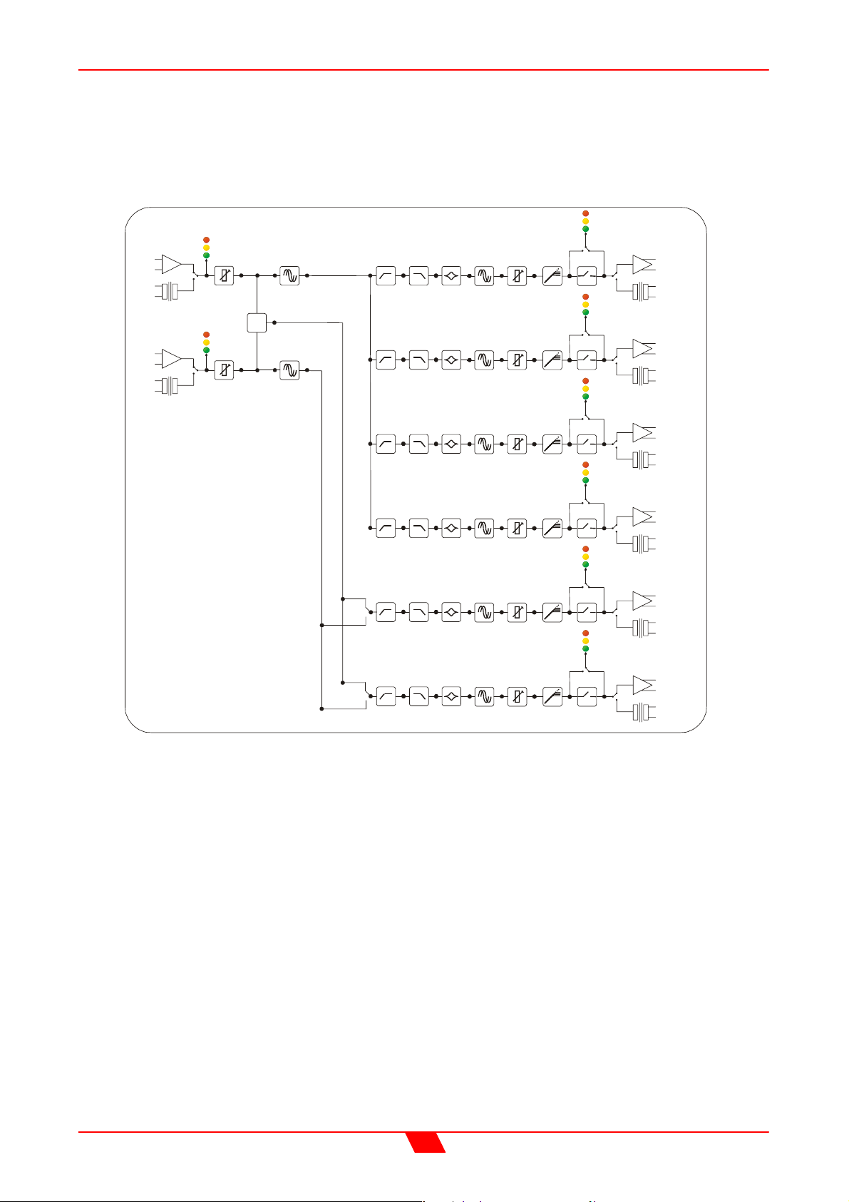
4 way + 2
This format feeds input A to outputs 1, 2, 3, and 4 designated low, lo-mid, hi-mid and high
respectively. Outputs 5 and 6 are configured as auxiliaries, with their source being either
input B, or the sum or inputs A and B.
INPUT
INPUT
B
ANALOGUE
SELECT
A
DIGITAL
ANALOGUE
SELECT
DIGITAL
GAIN MAIN DELAY
SUM
Σ
GAIN MAIN DELAY
HPF LPF PEQ x 5
LPF PEQ x 5
HPF
HPF
LPF
PEQ x 5
HPF
LPF
PEQ x 5
HPF
LPF
PEQ x 5
GAIN
DELAY
DELAY
DELAY
DELAY
DELAY GAIN LIMIT MU TE
GAIN
GAIN
GAIN
LIMIT MU TE
LIMIT MU TE
LIMIT MU TE
LIMIT MU TE
SELECT
SELECT
SELECT
SELECT
SELECT
ANALOGUE
DIGITAL
ANALOGUE
DIGITAL
ANALOGUE
DIGITAL
ANALOGUE
DIGITAL
ANALOGUE
DIGITAL
OUTPUT 1
LOW
OUTPUT 2
LO-MI D
OUTPUT 3
HI-MID
OUTPUT 4
HIGH
OUTPUT 5
AUX 1
SELECT
ANALOGUE
DIGITAL
OUTPUT 6
AUX 2
HPF LPF
PEQ x 5
DELAY
GAIN
LIMIT MU TE
AES/EBU Digital input and output interfaces are available as an option (factory fitted only).
Input and output balancing transformers are also available as an option (factory fitted only).
14
Page 15
DSO26 User Manual
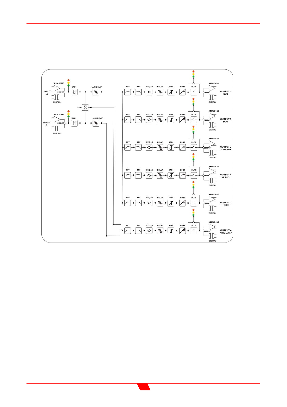
5 way + 1
This format feeds input A to outputs 1, 2, 3, 4, and 5 designated sub, low, lo-mid, hi-mid
and high respectively. Output 6 is configured as an auxiliary, with the source being either
input B, or the sum or inputs A and B.
AES/EBU Digital input and output interfaces are available as an option (factory fitted only).
Input and output balancing transformers are also available as an option (factory fitted only).
15
Page 16
DSO26 User Manual
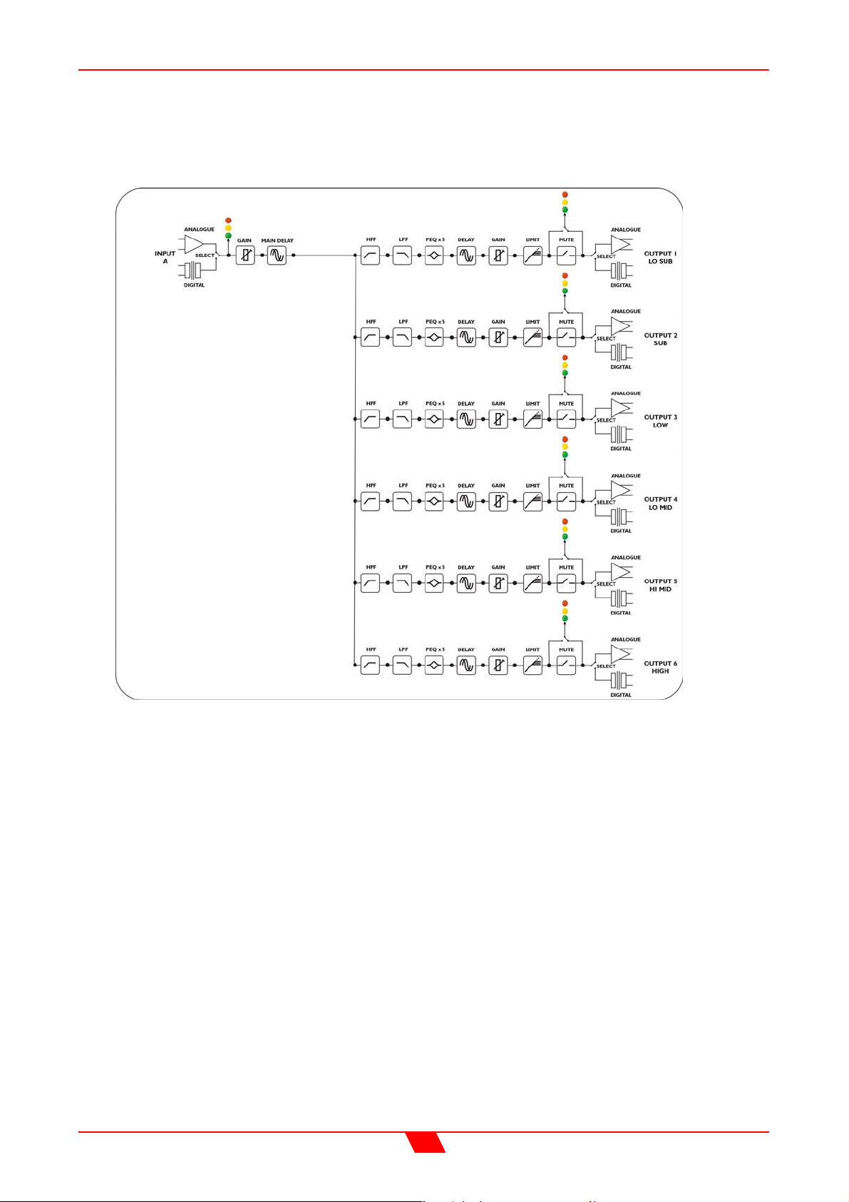
6 way
This format feeds input A to all outputs designated lo-sub, through high, 1 to 6
respectively.
AES/EBU Digital input and output interfaces are available as an option (factory fitted only).
Input and output balancing transformers are also available as an option (factory fitted only).
16
Page 17
DSO26 User Manual
C
X
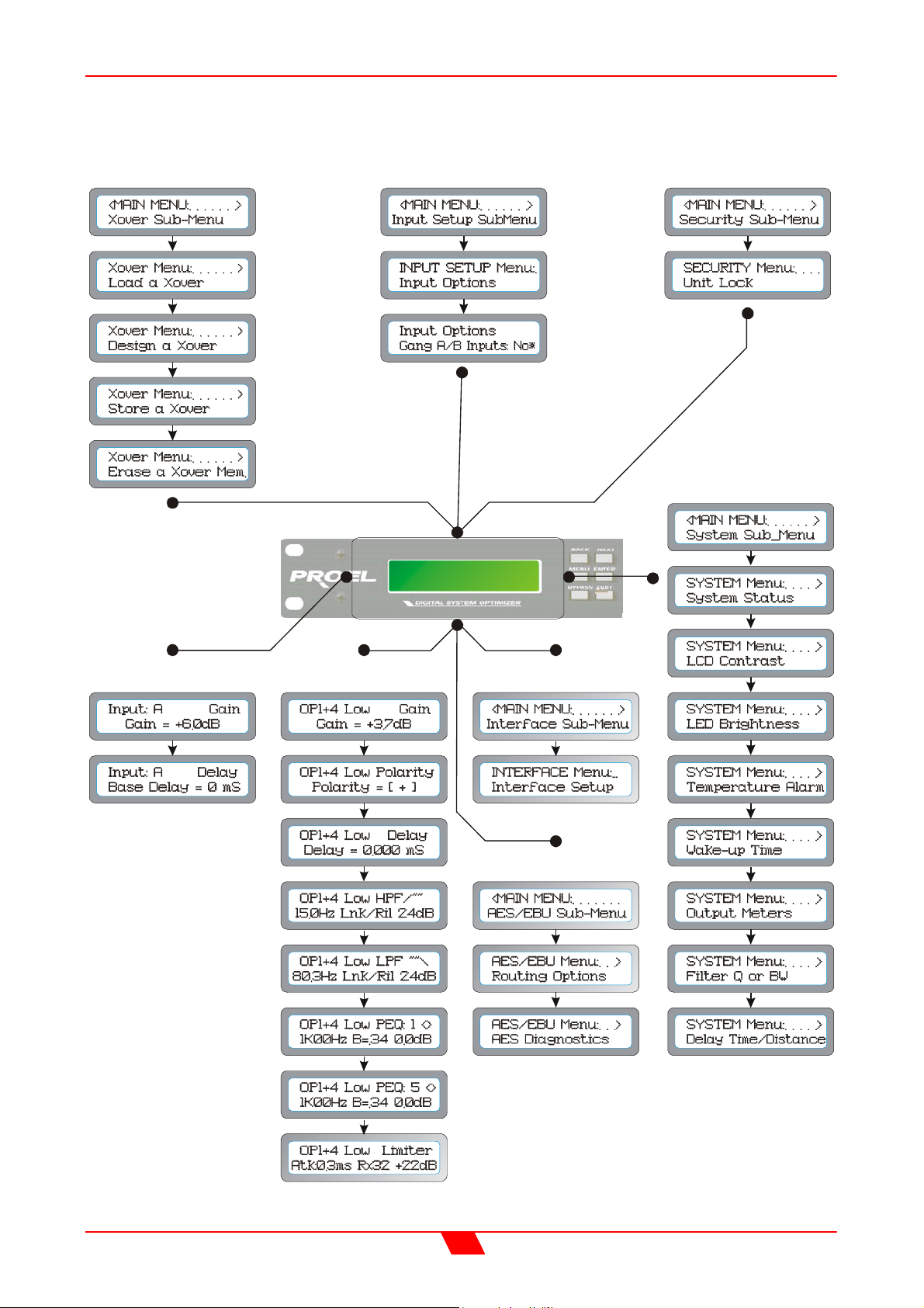
SCREEN LAYOUTS OVERVIEW
over Sub-Menu
Input Setup Sub-Menu
Security Sub-Menu
NEXT
MENU-ENT ER
MENU-NEXT-
-ENTER
Default Screen
rossover Name
INPUT
GAIN
OUTPUT
GAIN
Input Section Screens Output Section Screens
ENTER
MENU-NEX Tx3-
-ENTE R
MENU-NEXTx4-
-ENTER
Interface Sub-Menu
MENU
R
E
T
N
-E
2
EXTx
-N
System Sub-Menu
ENTER
NEXT
NEXT
NEXT
MENU-NEXTx5-
-ENTER
ENTER
AES/EBU Sub-Menu
ENTER
NEXT
PEQ’s 2 to 4
17
Page 18
DSO26 User Manual
AUDIO FUNCTION SCREENS
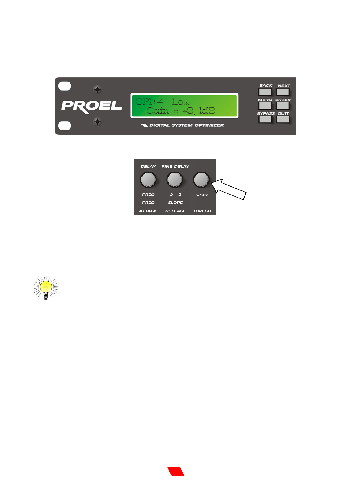
Gain Screen
To adjust the gain:
Use the ‘GAIN’ control.
Each input and output has an individual gain screen. The inputs have a range of +6dB to
–40dB, adjustable in 0.1dB steps and the outputs have a range of +15dB to –40dB, again
adjustable in 0.1dB steps.
For further details on this topic, see the section entitled
“Operating Level” on page 32.
18
Page 19
DSO26 User Manual
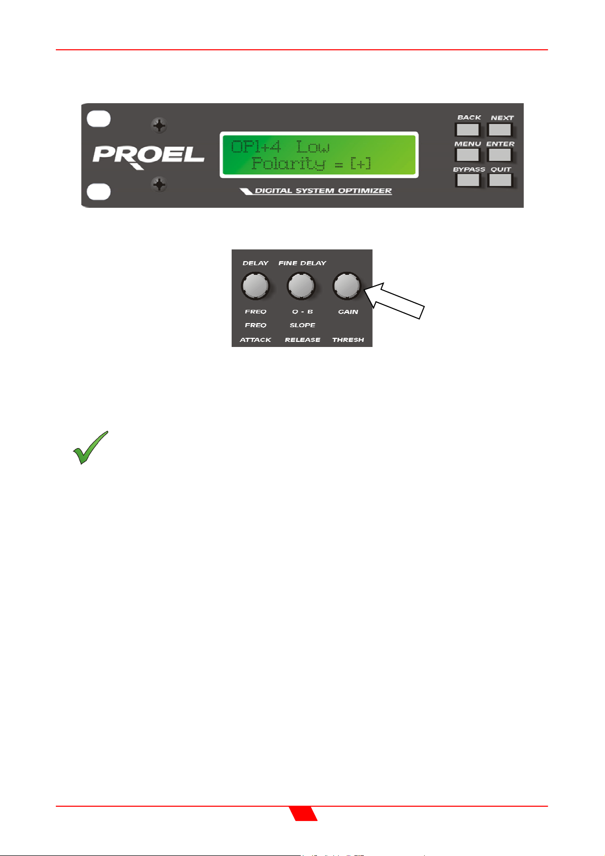
Polarity Screen
To adjust the polarity:
Use the ‘GAIN’ control to switch between + and -.
Each output has an independent polarity screen. This gives the flexibility to reverse (flip by
180°) the phase of individual outputs.
Note: When the outputs are ganged, the polarity screens remain individual.
19
Page 20
DSO26 User Manual
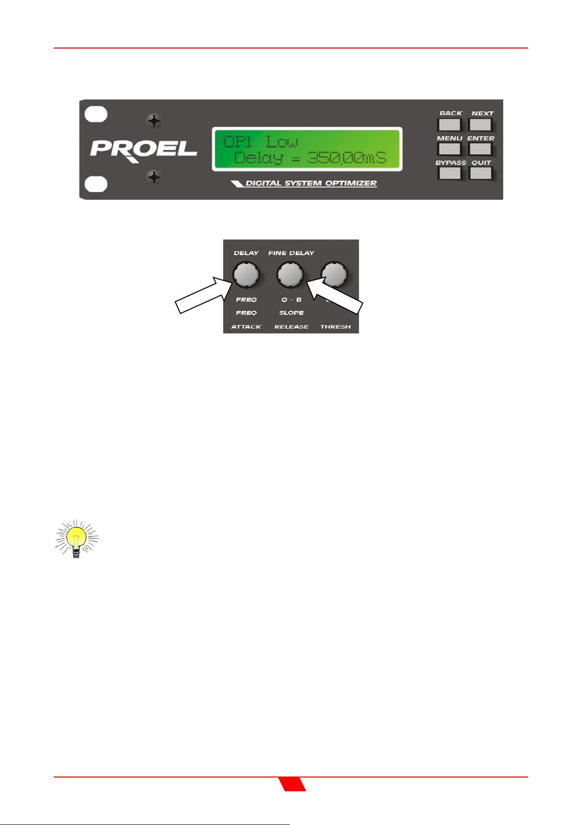
Delay Screen
To adjust delay settings:
Use the ‘DELAY’ control for coarse control. (1mS steps)
Use the ‘FINE DELAY’ control for fine control. (2.6µS steps)
Each input and output has an independent delay time control. Input delay (base delay) is
adjustable in 1mS steps. Output delay is adjustable in 2.6µS steps or in 1mS steps giving
complete control over driver time alignment.
The combination of input (base) delay and output delay can be a maximum of 650mS. So,
for example, setting a base delay of 500mS on input A will only leave 150mS for any
outputs that are sourced from input A. The exception to this rule is for any ‘aux’ outputs
(available in 4 and 5 way crossover modes). Choosing the source as a mono sum (Inputs
A + B) will allow 650mS of output delay, regardless of the input delay settings.
For further details on this topic, see the section entitled “Time Alignment” on
page 33.
20
Page 21
DSO26 User Manual
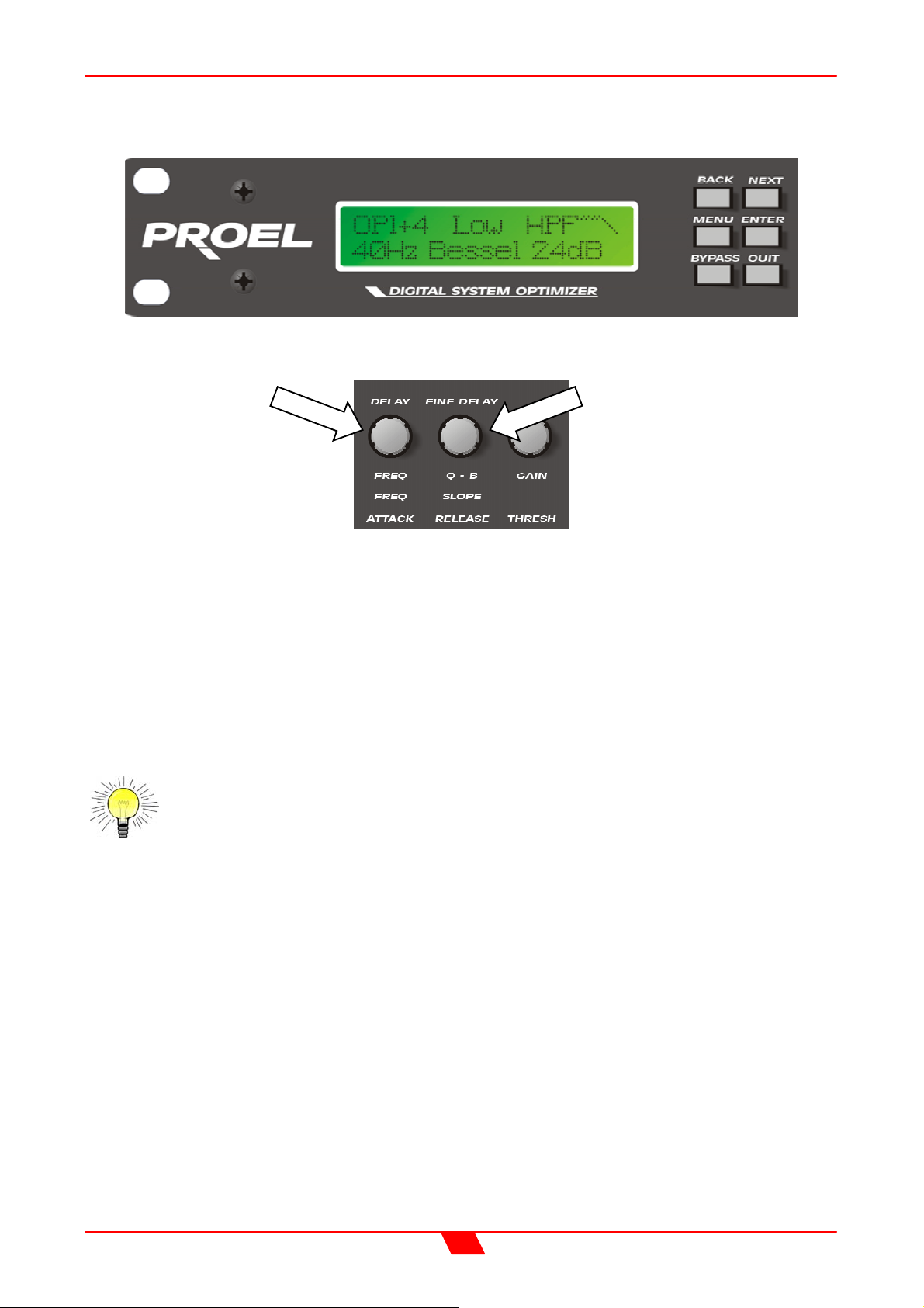
High and Low Pass Filter Screens
To adjust HPF/LPF settings:
Use the ‘FREQ’ control for the frequency.
Use the ‘SLOPE’ control for the slope.
Each output has an independent high pass filter and an independent low pass filter. Both
filters have a range of selectable slopes, which are Bessel 12dB, 18dB and 24dB,
Butterworth 12dB, 18dB and 24dB, and Linkwitz-Riley 24dB.
Highpass filters have a range of <10Hz (through) to 16kHz and Lowpass filters have a
range of 22kHz (through) to 39Hz in 1/36 octave steps.
HPFs and LPFs can be set asymmetrically.
For further details on this topic, see the section entitled “Crossover Filter Slopes”
on page 32.
21
Page 22
DSO26 User Manual
Parametric Equaliser Screen
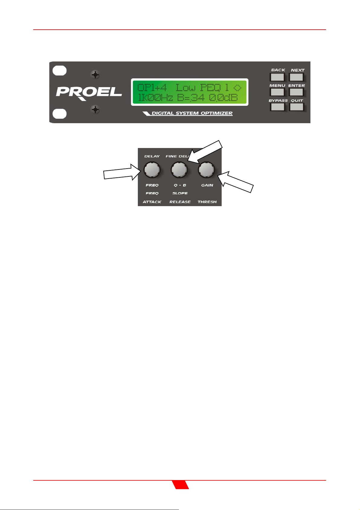
To adjust parametric settings:
Use the ‘FREQ’ control for the frequency.
Use the ‘Q’ control for the Q.
Use the ‘GAIN’ control for the gain.
Each parametric section can be positioned at a frequency from 20Hz to 20kHz and
features a wide range of 'Q’s to produce response curves ranging from broad to notch. The
gain control ranges from +15dB to -30dB in 0.1dB steps. Frequency steps are 1/36 octave
resolution for precise control. Since all filtering is achieved in DSP all settings are resettable with absolute accuracy and in ganged mode parameters track identically. Very
narrow band notch filters (maximum ‘Q’ of 128) can be achieved and unlike analogue
filters these tight ‘Q’ filters are entirely stable. The maximum notch depth is -30dB.
Parametric filters are carefully implemented using Double Precision processing. This
method is costly in terms of processing power but yields substantial benefits in terms of
the DSO26's exceptional noise performance and greatly improved low frequency stability.
(Note: To show parametric filters in bandwidth (BW) rather than ‘Q’, go into the ‘System
sub-menu’, select ’filter Q or BW’, select BW.)
To switch a filter from parametric mode to shelving mode, set the gain of the filter to 0dB
and then turn the ‘Q’ control anti-clockwise until ‘HiSHF’ or ‘LoSHF’ is displayed. Now set
the frequency and gain as required. To set the filter back to a parametric section, just
ensure that the gain is at 0dB, otherwise the ‘Q’ control will have no effect.
22
Page 23
DSO26 User Manual
Limiter Screen
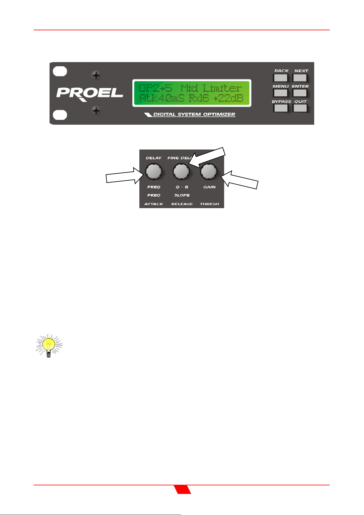
To adjust limiter settings:
Use the ‘ATTACK’ control to adjust the attack time.
Use the ’RELEASE’ control for the release time.
Use the ‘THRESH’ control for the limiter threshold.
Each output has an independent high performance limiter.
All limiters have an attack range of 0.3mS to 90mS, release times are 2, 4, 8, 16 and 32
times the attack time and thresholds range from +22dB to –10dB in 1dB steps.
If the automatic limiter time constant option is in use, all limiter screens will say ‘automatic’
and the time constants will be set from the high pass filter frequency. A table of dB to
Vrms, in case the amplifier sensitivity is given in Volts rather than dB, is in appendix 1.
The output meters are linked to the time constants of the limiters so true output metering is
achieved.
For further details on this topic, see the section entitled “Output Limiters” on
page 33.
23
Page 24
DSO26 User Manual
MENU SELECTION
The following menu selections are available:
Xover Sub-menu:
Load a Xover – loads a pre-defined crossover.
Design a Xover – starts the set-up wizard for designing a new crossover.
Store a Xover – stores all output settings as a defined crossover.
Erase a Xover Mem. – erase an individual crossover memory.
Input Set-up Sub-menu:
Gang Inputs - Allows ganging of inputs for stereo operation.
Security Sub-menu:
Locks the unit with a 4 digit code, at one of many user definable levels.
DO NOT ENTER THIS MENU BEFORE HAVING THOROUGHLY UNDERSTOOD THE
WAY THE LOCK-OUT WORKS, AS DESCRIBED ON PAGE 27.
System Sub-menu:
System Status – displays unit info, such as version & internal temperature.
LCD Contrast – adjusts the contrast of the LCD screen.
LED Brightness – adjusts the brightness of all indicator LEDs.
Temperature Alarm – sets a temperature warning threshold in °C.
Wake-up Time – sets time take for unit to pass audio after power-up.
Output Meters – selects whether meters are monitoring pre or post mute.
Filter Q or BW – selects display type for parametric filter screens.
Delay Time/Distance – select units to display delays in (mS/m/ft)
Interface Sub-menu:
Interface Setup – enable/disable interface and set baud rate.
AES/EBU Sub-menu:
Routing Options – select various routing options.
AES Diagnostics – shows complete status of AES signal.
(Only available if the AES/EBU option is fitted.)
24
Page 25

DSO26 User Manual
INPUT SETUP SUB-MENU
There is one option in this menu:
Gang Inputs
Gangs A and B inputs so that precise adjustments can be made to both inputs
simultaneously. Both GAIN LEDs will light when the inputs are accessed and the LCD will
show A+B. All adjustments are now absolute and any adjusted parameters on both
channels will become identical . If it is necessary to introduce an off-set on any parameter,
un-gang the inputs, and adjust. If re-ganged, channel B will jump to channel A’s setting.
25
Page 26
DSO26 User Manual
X-OVER SUB-MENU
Load a Xover
Loads a stored crossover from the selection available. Enter accepts the selected name
and loads immediately.
Design a Xover
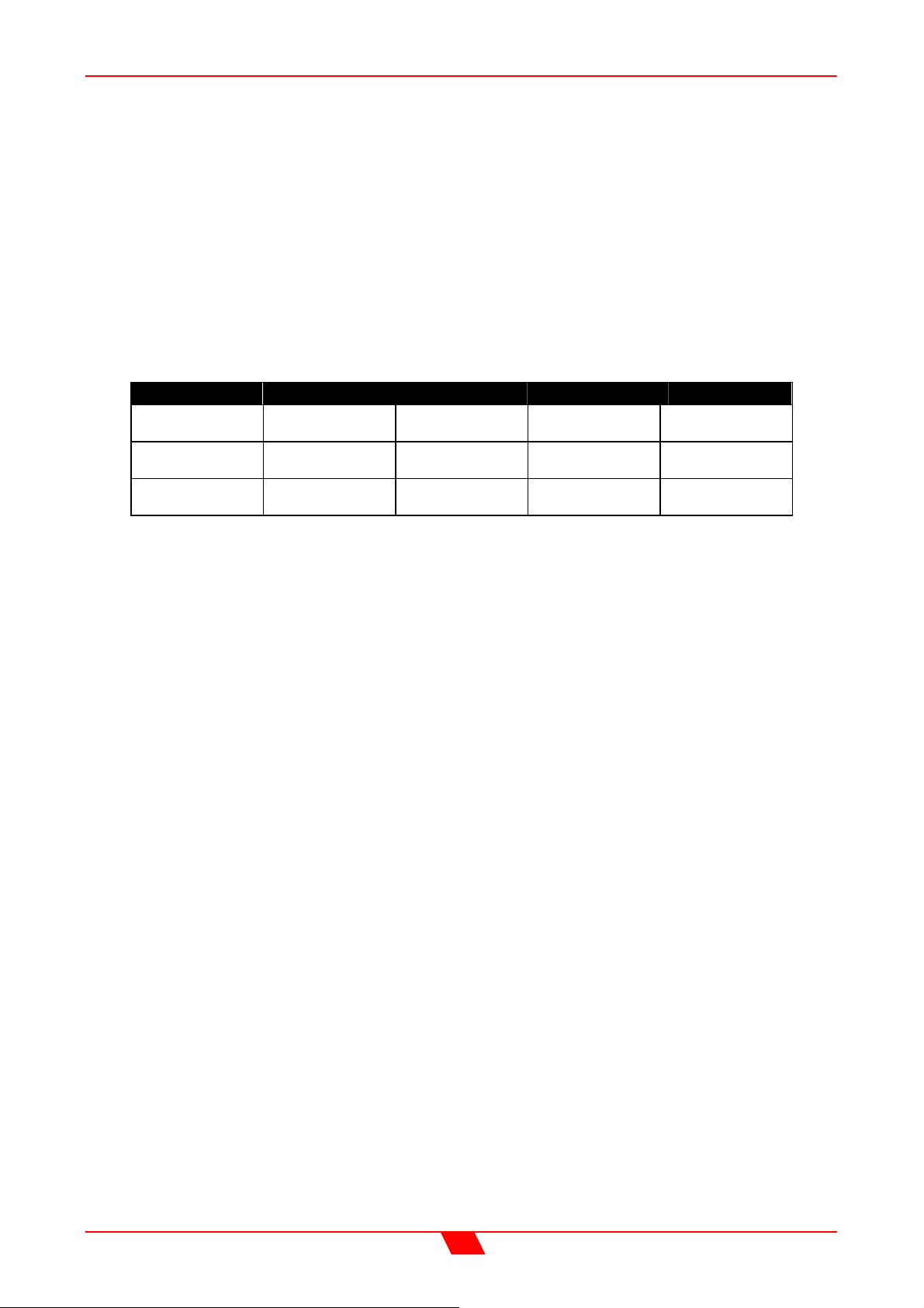
Opens a wizard to design a crossover. Options include format type, ganging of outputs,
routing and automatic limiter time constants. The table below outlines which options are
available dependant on what type of crossover is chosen for the design.
2 x 2 Way 2 x 3 Way 4 Way 5 Way 6 Way
Out 5
Source:A/A+B
Gang
Outputs:Yes/No
Auto Limit
TC:Yes/No
Gang
Outputs:Yes/No
Auto Limit
TC:Yes/No
Out 6
Source:A/A+B
Auto Limit
TC:Yes/No
Out 6
Source:A/A+B
Auto Limit
TC:Yes/No
Auto Limit
TC:Yes/No
Store a Xover
Stores a X-over (all output settings) to one of 9 locations. Crossovers can be named, using
the same method as memories, with up to 16 characters which appear in the default
screen on the top line of the display.
Erase a Xover Mem
Permits clearing (erasing) of individual crossover memories from the unit. Note that, once
erased, the memory name disappears from the list of recallable locations. If the crossover
memory is currently in use, it’s name will remain on the default screen, and the current
settings will not be changed.
26
Page 27

DSO26 User Manual
SECURITY SUB-MENU
After selecting the ‘Security Sub-Menu’ and pressing ENTER, select one of the lock types,
after choosing the most appropriate one for your application. As ever, ENTER will confirm
your selection.
User Specific
Upon pressing ENTER to select this type of lock, each parameter group is presented in
turn. Choose the type of lock (as above) using the FREQ encoder, and press ENTER to
confirm each parameter. After the last parameter, the unit requests a password. The
description of this operation is given at the end of this section.
This option allows the user to specify, for each type of parameter, whether it is to be
completely accessible (‘No Lock’), viewable but not adjustable (‘Control’), or effectively
unavailable (‘Display’). The ability to operate mutes, store or recall memories, or even
access the menus may also be locked.
Xover Only
All input parameters are available, but only the gain trim is available on the outputs,
effectively locking all the crossover settings. All mutes remain active.
Xover + Trim
All input parameters available, but no output parameters – the crossover sections are
completely locked. All mutes remain active.
Xover + Trim + Mute
As for ‘Xover + Trim’ but additionally, output mutes are locked. Input mutes remain active.
Changes Only
All parameters may be viewed, but none may be adjusted. This applies to both inputs and
outputs. All mutes remain active.
Changes + View
No parameters are accessible – in effect the GAIN keys do nothing. All mutes remain
active.
Changes + Mutes
All parameters may be viewed, but none may be adjusted. This applies to both inputs and
outputs. All mutes are also locked.
EVERYTHING
No parameters are accessible – in effect the GAIN and MUTE keys do nothing.
27
Page 28
DSO26 User Manual
Entering the Password to Complete the Locking Operation
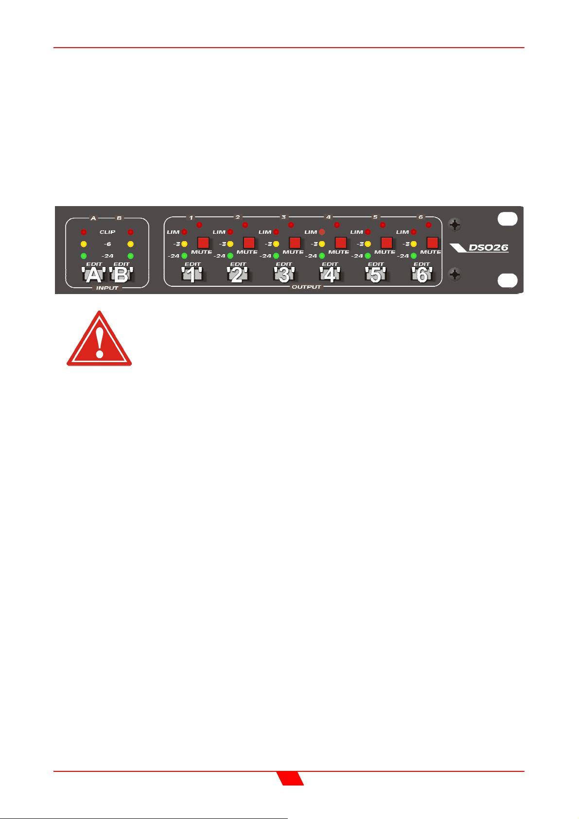
After selection of the lock type from the list above, a four-digit security code will be asked
for. This can be entered by using the ‘FREQ’ control to select a character, and the ‘BACK’
and ‘NEXT’ keys to move to the next character.
Alternatively, the ‘GAIN’ keys can be used to enter a code by pressing any combination of
the eight buttons. Each ‘GAIN’ key represents its channel labelling, so any combination of
A, B, 1, 2, 3, 4, 5 and 6 can be used as a code, as shown below.
IMPORTANT - Please note your code! If the security code number is
forgotten contact your local sales office.
28
Page 29

DSO26 User Manual
SYSTEM SUB-MENU
System Status
Displays unit information including software version and temperature.
Curr. Temp. = current temperature in degrees Celsius.
Max1. Temp. = maximum temperature this session.
Max2. Temp. = maximum temperature ever reached.
LCD Contrast
Adjusts the LCD contrast from 0 to 100.
LED Brightness
Adjusts the LED brightness from 1 to 15.
Temperature Alarm
Sets a temperature warning between 20 and 80°C. The default screen will flash ‘ALARM.
Temp = n°C’ when the specified temperature is reached. (N.B. the warning does not affect
the units’ performance in any respect.)
Wake-up Time
Sets how the unit starts up with one of the following options.
0 to 60 seconds: Waits the specified time before unit wakes up.
Mute hold: Turns on and holds all output mutes when turned on.
(N.B. Wake-up is a slow ramp in level for about 5 seconds.)
Output Meters
Selects whether the output meters are pre or post mute. If the meters are set to read premute, they will still show the level, even if the channel has been muted.
Filter Q or BW
Selects whether ‘Q’ or Bandwidth is displayed in the parametric screens.
Delay Time/Distance
Selects whether delay is displayed in milliseconds, metres, or feet.
29
Page 30
DSO26 User Manual
INTERFACE SUB-MENU
Interface Setup
If the interface is enabled, the option will become available to select the baud rate. This
must be set to match tat on the PC to be used for the program update. Typically, the setup would be as below.
30
Page 31

DSO26 User Manual
AES / EBU SUB-MENU
Connection of AES/EBU signals is via the existing rear panel XLR connectors.
With the AES/EBU option fitted, AES Receive and Diagnostic modes are provided.
Routing Options
Selects the input source – either analogue or digital, and similarly the output source, again
either analogue or digital.
AES Diagnostics
Reports validity flag, clock speed and errors present in the incoming AES digital signal.
AES / EBU Connections
The AES/EBU digital signal is a stereo data stream, and so only one input XLR and three
output XLRs are used for the digital interface.
The connections are as follows:
Input A - Analogue Input at all times
Input B - Switchable between digital (stereo) input and analogue input
Output 1 - Switchable between digital out (for channels 1 & 2) and analogue out 1
Output 2 - Switchable between digital out (for channels 3 & 4) and analogue out 2
Output 3 - Switchable between digital out (for channels 5 & 6) and analogue out 3
Output 4 - Analogue output 4 only
Output 5 - Analogue output 5 only
Output 6 - Analogue output 6 only
31
Page 32
DSO26 User Manual
OPERATING NOTES
Operating Level
With any audio signal processing equipment it is necessary to ensure adequate signal
level is used through the device, to avoid sacrificing noise performance. With equalisation
in use it may be necessary to reduce the input level, as gain within the unit may cause
digital clipping, indicated by the top red LED's lighting independently of the rest of the
meter.
It should be noted that the figure quoted for the maximum input level options is the clipping
point for that option (not a safe operating level). Always ensure that this clipping point is no
lower than that for the following equipment in the signal chain, and allow extra margin if
equalisation sections are boosted.
Grounding
The Screen (shield) pins on all audio connectors are normally connected directly to the
ground pin of the IEC mains inlet. The chassis is also directly connected to this pin.
Never operate this unit without the mains safety ground connected. Signal ground (0V) is
in turn connected to the chassis ground.
To avoid ground loops, cable shields should be connected to ground at one end only. The
normal convention is that the shield is only connected at the output XLR.
Crossover Filter Slopes
Please consult the block diagrams on page 12 for details of the various configurations
available. All crossover modes feature adjustable crossover frequencies with a choice of
slopes, 5 bands of driver compensation E.Q. per output and delay time plus limiters for
each output. A powerful 8 band parametric equaliser is also provided on each input for
room equalisation. Phase reverse is provided for each output.
A choice of Bessel or Butterworth slopes at 12/18/24dB per octave and Linkwitz-Riley at
24dB per octave are provided. Since Low and High pass functions are separately
adjusted, asymmetric slopes are easily achieved, if required. It should also be noted that
the turnover frequency displayed on the DSO26 is the -3dB point for all slopes except
24dB Linkwitz-Riley where the -6dB point is shown. If the -6dB point is to be used for the
Bessel or Butterworth filter, take the required crossover frequency, multiply this by the
appropriate factor from the following table and then select the closest available frequency
on the DSO26's display.
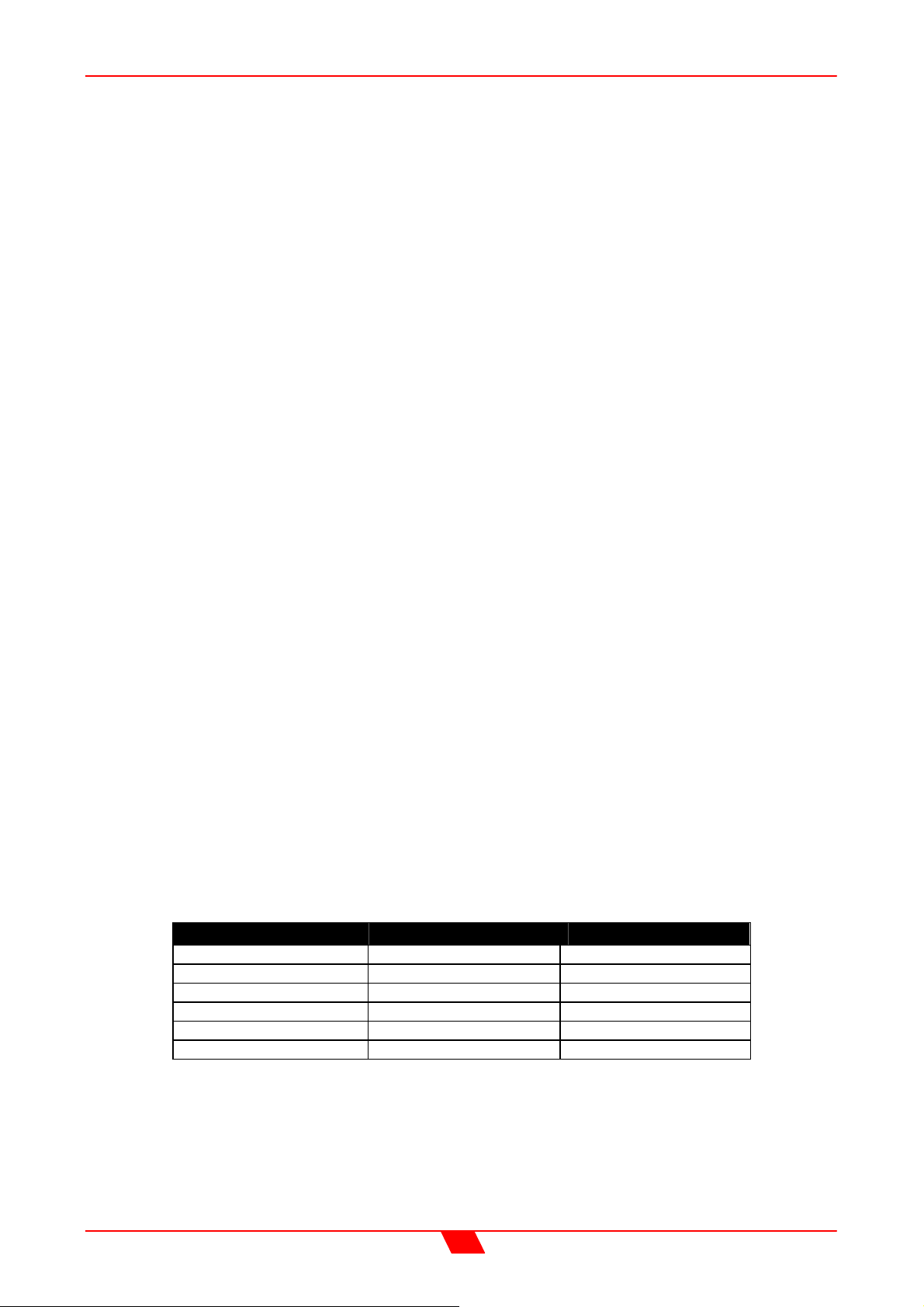
Filter Type High pass factors Low pass factors
Bessel 12dB/Oct. 1.45 0.69
Butterworth 12dB/Oct. 1.31 0.76
Bessel 18dB/Oct. 1.37 0.73
Butterworth 18dB/Oct. 1.19 0.84
Bessel 24dB/Oct. 1.35 0.74
Butterworth 24dB/Oct. 1.15 0.87
Please note that unlike conventional analogue crossovers, crossover points and slopes
are set with absolute accuracy since component tolerance problems do not occur.
32
Page 33
DSO26 User Manual
Time Alignment
A further advantage of the DSO26 over conventional products is the provision of an
independently adjustable delay section for each output. This allows the true arrival time
from multiple drivers to precisely aligned rather than relying on the compromise 'phase
adjust' approach. Delay time is adjustable in 2.6µS steps (1mm).
Please see page 20 for details of how to adjust the delay times.
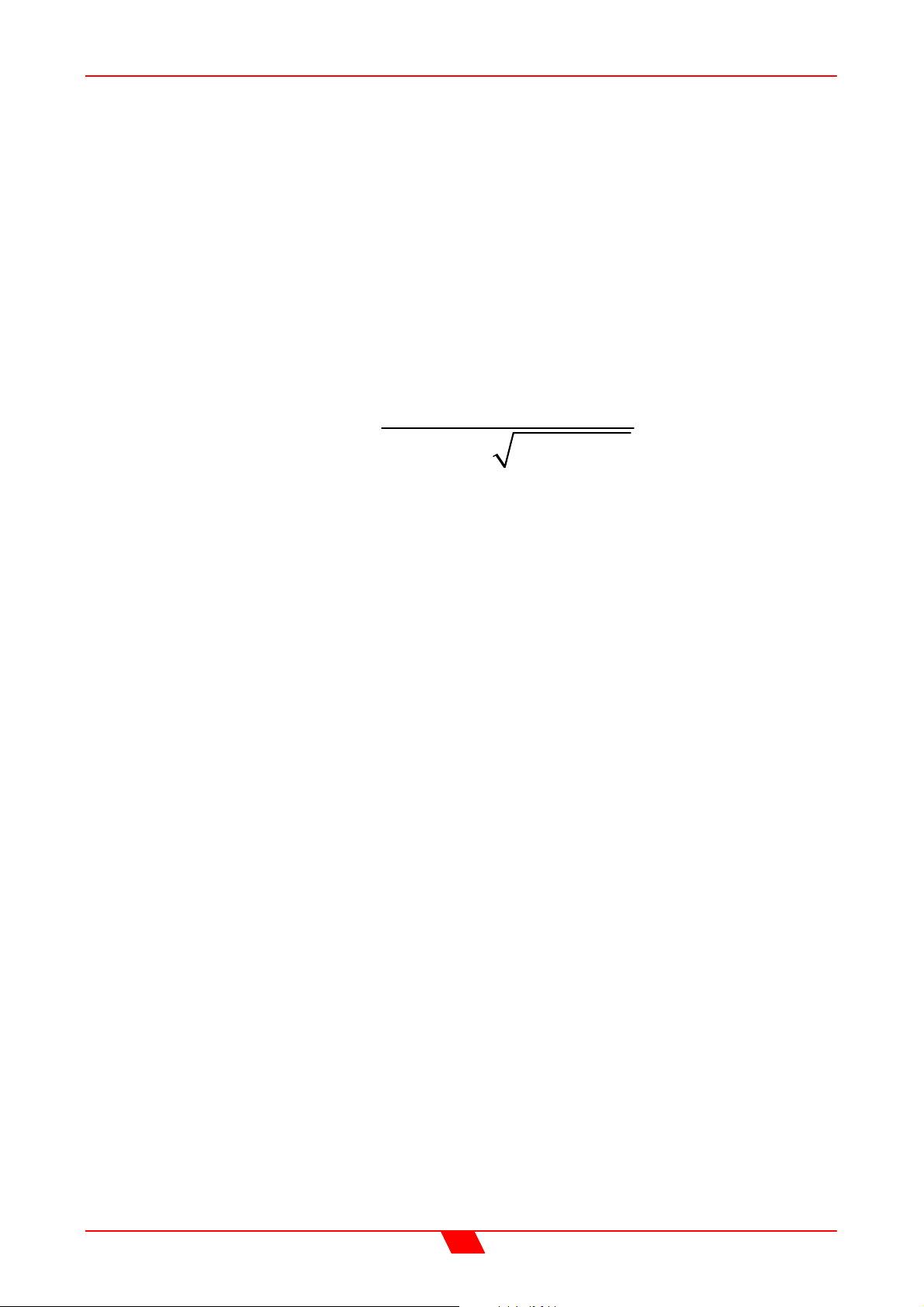
To convert from units of time (i.e. milliseconds) to units of distance use the following
formula:
1 343ms mm=
To calculate time delay for a known distance, use:
T
delay
where:
L = Distance in meters
°C is the temperature in °C.
To simplify this equation at 20°C:
Note: Centigrade = (Fahrenheit –32) x 0.5555.
=
T
(1.126ft) @ 20°C (68° F)
20,06 273
= L [meters] x 2.192
delay
T
delay
++°
= L [feet] x 0.955
L
C
33
Page 34
DSO26 User Manual
Output Limiters
High performance digital limiters are provided for each output with control over attack time,
release time and threshold level parameters - see page 23 for details. This level of control
allows the user to balance the required subjective quality of the limiter against the driver
protection requirements. It does also mean that an incorrectly set limiter may sound awful!
In particular, as with all limiters, using too fast an attack or release time will result in
excessive low frequency distortion. In the ‘Design a Xover’ sub-menu there is an option for
automatic limiter time constants.
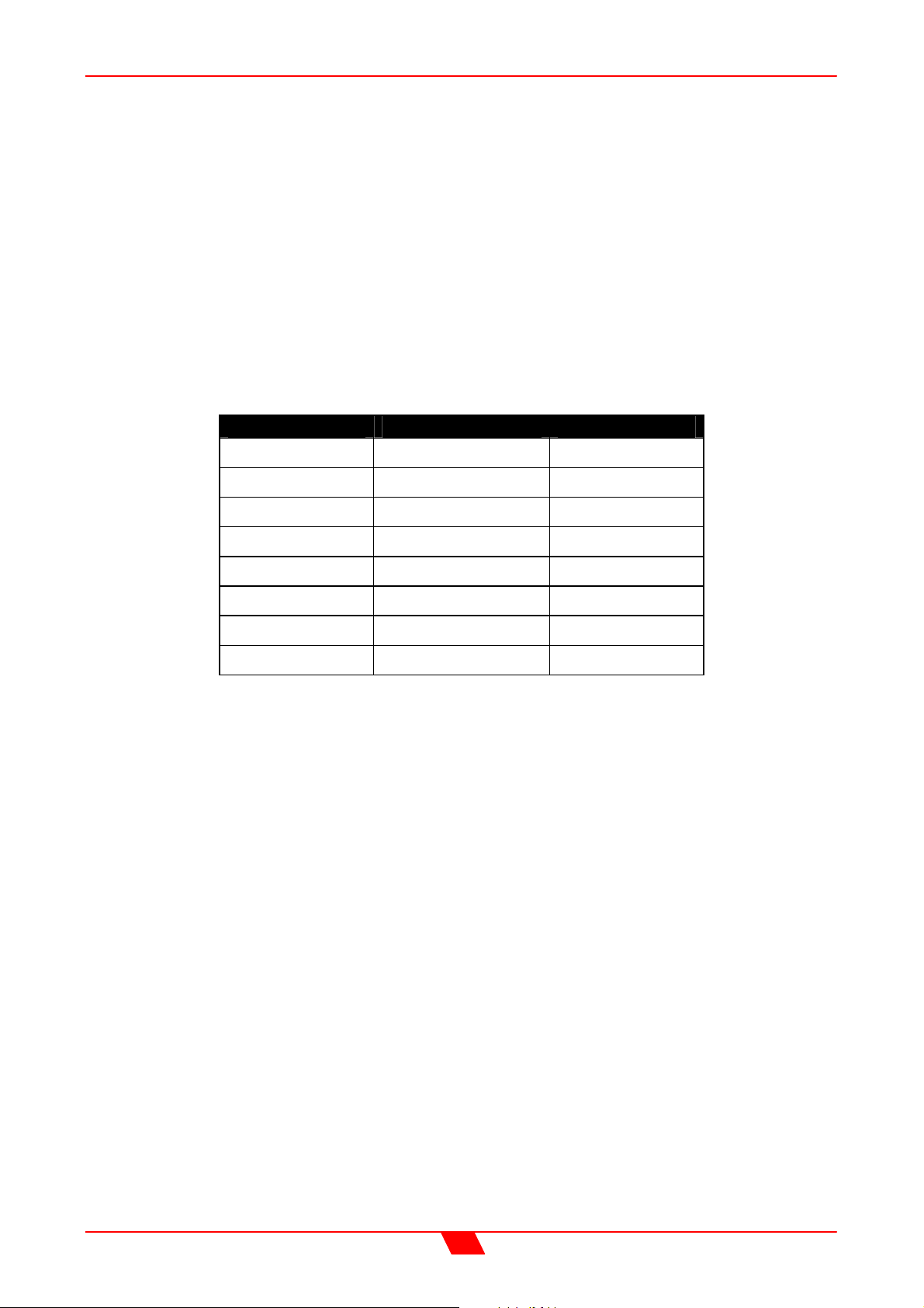
In this mode the time constants will be automatically set from the Highpass filter frequency
according to the table below.
The time constants are set by the high pass filter frequency for that channel.
High Pass Filter Auto Attack Time Release Time
<10Hz – 31Hz 45mS x16 (720mS)
31Hz – 63Hz 16mS x16 (256mS)
63Hz – 125Hz 8mS x16 (128mS)
125Hz – 250Hz 4mS x16 (64mS)
250Hz – 500Hz 2mS x16 (32mS)
500Hz - 1kHz 1mS x16 (16mS)
1kHz – 2kHz 0.5mS x16 (8mS)
2kHz – 22kHz 0.3mS x16 (4mS)
34
Page 35
DSO26 User Manual
Setting Accurate Limiter Thresholds
The limiters built into the DSO26 are intended to be used for for loudspeaker driver
protection, as opposed to amplifier protection. All modern professional power amplifiers
designed for live sound use have their own limiters which are tailored to protecting the
amplifier from clipping.
The following section describes how to set up the DSO26’s limiters to provide exceptional
protection against driver overheating, and cone over-excursion.
Most speaker systems are given a power rating in Watts RMS. This is the maximum
continuous power that the system will handle and often appears very conservative. In
reality, as music program is far from continuous in nature, the peak power of the system is
much higher – up to ten times the continuous figure. Any limiter, which is to protect the
driver from damage, must be able to fulfil the following tasks.
Have an attack time which is calculated to allow transients through but keep the RMS level
below the speaker manufacturers specification;
Have a release time which is sufficiently long to avoid the limiter itself modulating the
program ;
Be intelligent enough to adjust the envelope of the limiter according to the frequency
content of the program material.
The DSO26’s limiters are capable of performing all these tasks. The only parameter which
the user must set manually is the threshold, and it is crucial that this is done correctly.
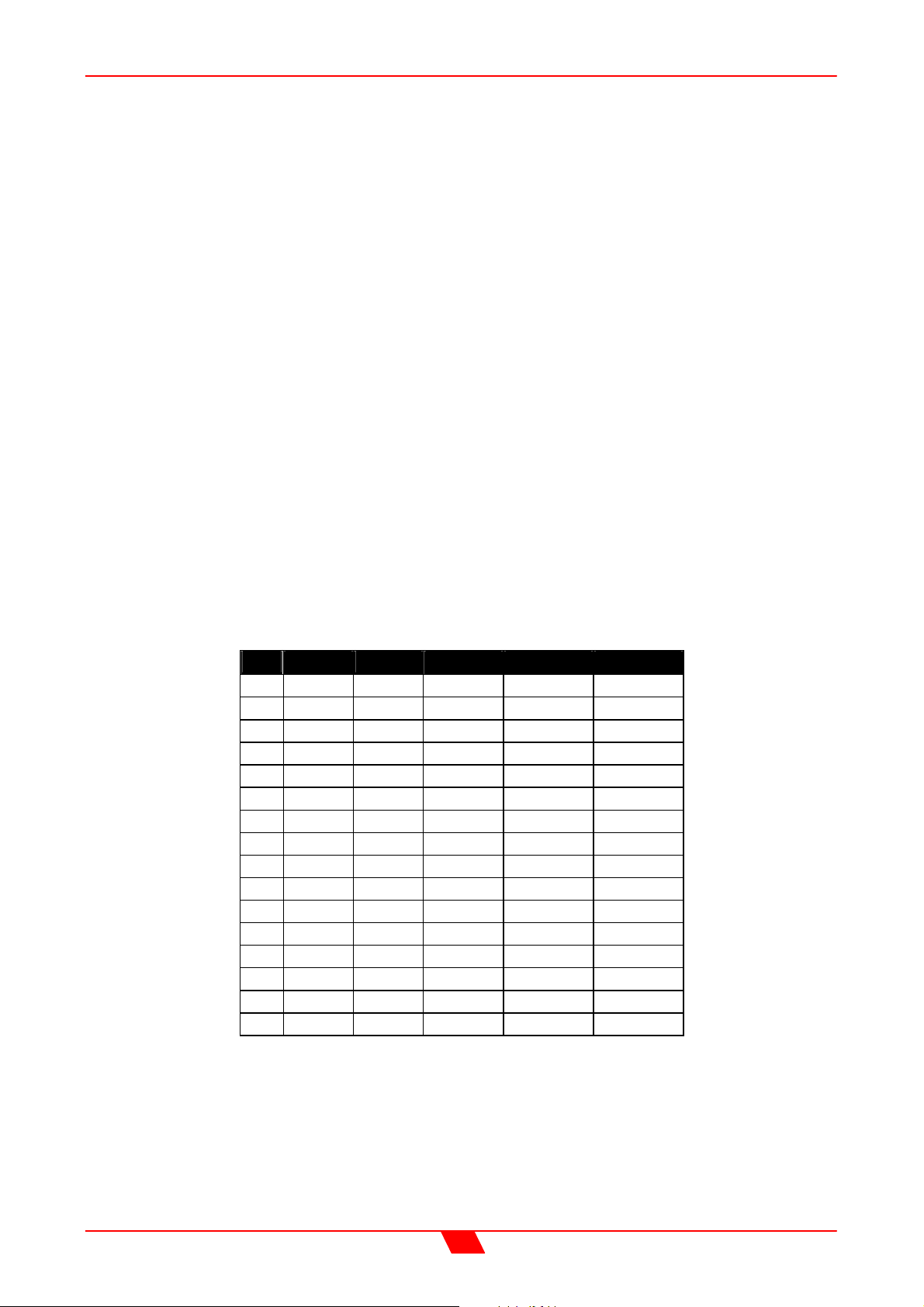
Consider the table below.
dB Ratio Vrms
45 177.83 137.74 2371.71 4743.42 9486.83
44 158.49 122.77 1883.91 3767.83 7535.66
43 141.25 109.41 1496.45 2992.89 5985.79
42 125.89 97.52 1188.67 2377.34 4754.68
41 112.20 86.91 944.19 1888.39 3776.78
40 100.00 77.46 750.00 1500.00 3000.00
39 89.13 69.04 595.75 1191.49 2382.98
38 79.43 61.53 473.22 946.44 1892.87
37 70.79 54.84 375.89 751.78 1503.56
36 63.10 48.87 298.58 597.16 1194.32
35 56.23 43.56 237.17 474.34 948.68
34 50.12 38.82 188.39 376.78 753.57
33 44.67 34.60 149.64 299.29 598.58
32 39.81 30.84 118.87 237.73 475.47
31 35.48 27.48 94.42 188.84 377.68
30 31.62 24.49 75.00 150.00 300.00
Using this table it is a straightforward procedure to work out the required setting of the
limiter thresholds for the system. Follow the steps described overleaf.
First, check the RMS power rating of the speaker system, and its impedance.
Look up this value in the table above, using the closest value below the rated power of the
speaker system. Note the corresponding ‘dB’ value.
Check the gain of your amplifier, which needs to be in ‘dB’.
Pwr 8 Ω Pwr 4 Ω Pwr 2 Ω
35
Page 36

DSO26 User Manual
Subtract this gain figure from the dB value obtained from the table to find the required
absolute setting for the limiter thresholds.
Note that, for safety, always set the limiter threshold 1 or 2 dB below the maximum
allowable worked out using the above method.
ALWAYS REFER TO YOUR SPEAKER MANUFACTURER FOR LIMITER
SETTINGS.
36
Page 37
DSO26 User Manual
FACTORY PRESETS
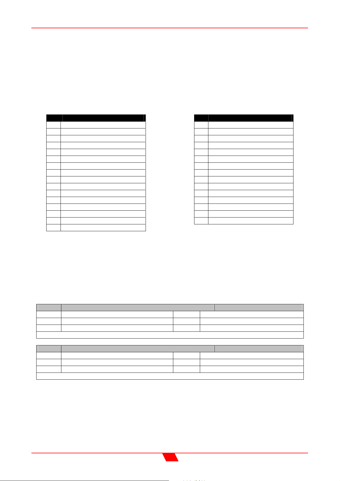
DSO26 is factory preloaded with presets for the EDGE and TFL loudspeaker lines.
The presets were optimized by engineers at Proel to achieve the best performance.
As a general rule Sat and Aux outputs are not locked and can be programmed by users to
fulfill their needs. All Aux outputs are muted by default.
Sub out gain is trimable, its limiter thresholds are generally left free and the delay time is
unlocked. The default time alignement was calculated in Proel’s anechoic chamber taking
into account the most common speaker placement positions.
No Preset Name
10 EDGE121SP+212P A
11 EDGE218SP+212P A
12 EDGE121+218+212A
13 EDGE121SP+212P B
14 EDGE218SP+212P B
15 EDGE121+218+212B
16 Sub+EDGE15CXP BA
17 EDGE121SP + SAT
18 AUX + TFL10 BA
19 AUX + TFL12 BA
20 AUX + TFL15 BA
21 AUX + TFL152 BA
22 AUX + TFL212 BA
23 TFL115SP + SAT
24 TFL115SP + 10 P BA
25 TFL115SP + 12 P BA
Note: Always check Proel website http://www.proelgroup.com for updates.
No Preset Name
26 TFL115SP + 15 P BA
27 TFL118SP + SAT
28 TFL118SP + 10 P BA
29 TFL118SP + 12 P BA
30 TFL118SP + 15 P BA
31 TFL118SP + 152P BA
32 TFL215SP + SAT
33 TFL215SP+12P BA
34 TFL215SP+15P BA
35 TFL215SP+152P BA
36 TFL215SP+212P BA
37 TFL218SP + SAT
38 TFL218SP+15P BA
39 TFL218SP+152P BA
40 TFL218SP+212P BA
EDGE presets
There are two versions of EDGE presets, A and B. These differ in the high frequency
shelving presets. Version A is suited for indoor applications or when EDGE 212P are not
arrayed. Version B is for outdoor applications or when EDGE 212P are arrayed, resulting
in a better dispersion pattern.
10 EDGE121SP+212P A 2x3 way crossover
Out 1 Sub Out 4 Sub
Out 2 Mid Out 5 Mid
Out 3 High Out 6 High
Allowed Sub gain trim and delay time; normal High shelving eq.
11 EDGE218SP+212P A 2x3 way crossover
Out 1 Low Out 4 Low
Out 2 Mid Out 5 Mid
Out 3 High Out 6 High
Allowed Low gain trim and delay time; normal High shelving eq.
37
Page 38
DSO26 User Manual
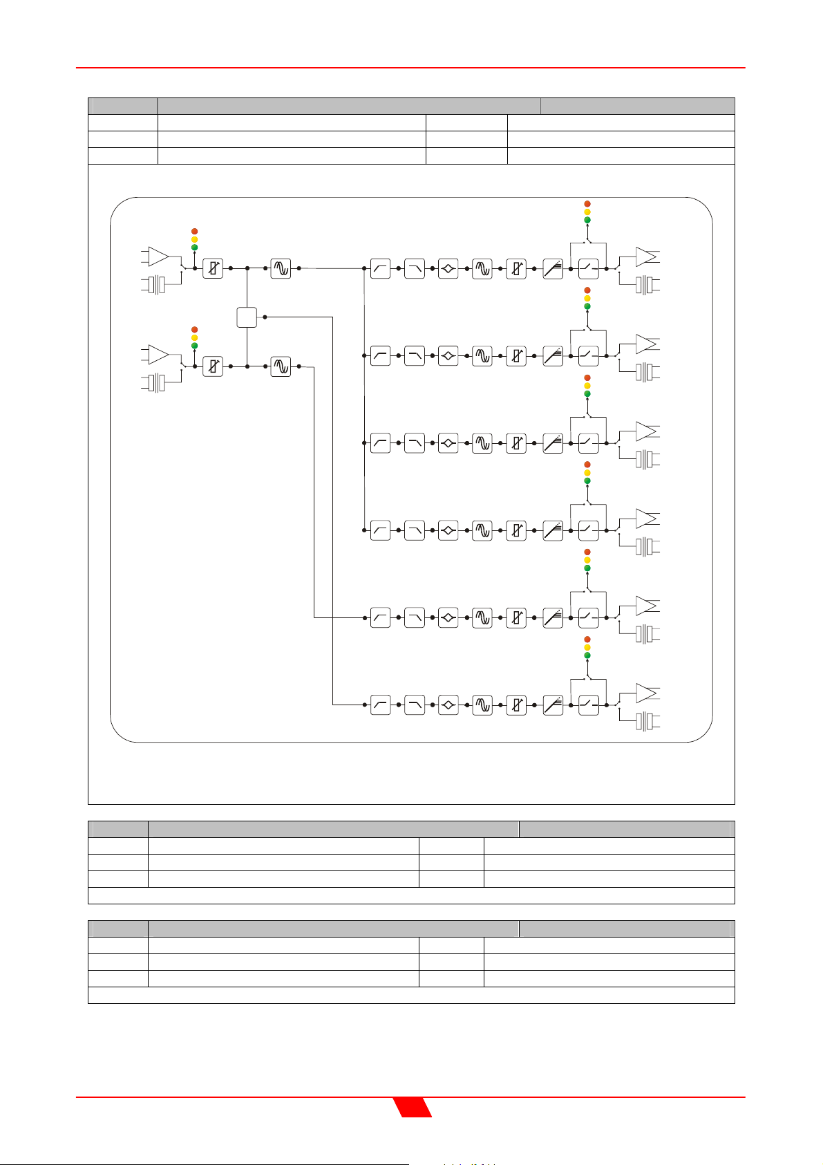
12 EDGE121+218+212A 4 way crossover plus 2 aux’s
Out 1 Low Out 4 Sub
Out 2 Mid Low Out 5 B2Sub
Out 3 Mid High Out 6 Aux
Allowed Sub, B2Sub gain trim and delay time; normal High shelving eq.
INPUT
A
INPUT
B
ANALOGUE
SELECT
DIGITAL
ANALOGUE
SELECT
DIGITAL
GAIN
GAIN
SUM
Σ
MAIN DELAY
MAIN DELAY
HPF LPF
HPF
HPF
HPF
HPF
SELECT
SELECT
SELECT
SELECT
SELECT
ANALOGUE
DIGITAL
ANALOGUE
DIGITAL
ANALOGUE
DIGITAL
ANALOGUE
DIGITAL
ANALOGUE
OUTPUT 1
LOW
OUTPUT 2
MID LOW
OUTPUT 3
MID HIGH
OUTPUT 4
SUB
OUTPUT 5
B TO SUB
PEQ x 5
LPF
PEQ x 5
LPF
PEQ x 5
LPF
PEQ x 5
LPF
PEQ x 5
GAIN
DELAY
DELAY GAIN LIMI T MUTE
DELAY GAIN LIMI T MUTE
DELAY GAIN LIMI T MUTE
DELAY GAIN LIMI T MUTE
LIMIT MUTE
DIGITAL
HPF LPF
PEQ x 5
DELAY GAIN LIMI T MUTE
ANALOGUE
SELECT
DIGITAL
AES/EBU Digital input and output interfaces are available as an option (factory fitted only).
Input and output balancing transformers are also available as an option (factory fitted only).
13 EDGE121SP+212P B 2x3 way crossover
Out 1 Sub Out 4 Sub
Out 2 Mid Out 5 Mid
Out 3 High Out 6 High
Allowed Sub gain trim and delay time; increased High shelving eq.
14 EDGE218SP+212P B 2x3 way crossover
Out 1 Low Out 4 Low
Out 2 Mid Out 5 Mid
Out 3 High Out 6 High
Allowed Low gain trim and delay time; increased High shelving eq.
OUTPUT 6
AUXILI ARY
38
Page 39
DSO26 User Manual
15 EDGE121+218+212B 4 way crossover plus 2 aux’s
Out 1 Low Out 4 Sub
Out 2 Mid Low Out 5 B2Sub
Out 3 Mid High Out 6 Aux
Allowed Sub, B2Sub gain trim and delay time; increased High shelving eq.
16 Sub+EDGE15CXP BA 2x3 way crossover
Out 1 Sub Out 4 Sub
Out 2 Low Out 5 Low
Out 3 High Out 6 High
Allowed Sub gain trim, limiter threshold and delay time
17 EDGE121SP + SAT 2x3 way crossover
Out 1 Sub Out 4 Sub
Out 2 Sat Out 5 Sat
Out 3 Aux Out 6 Aux
TFL presets
TFL presets are intended to optimse the performance of the TFL loudspeaker line.
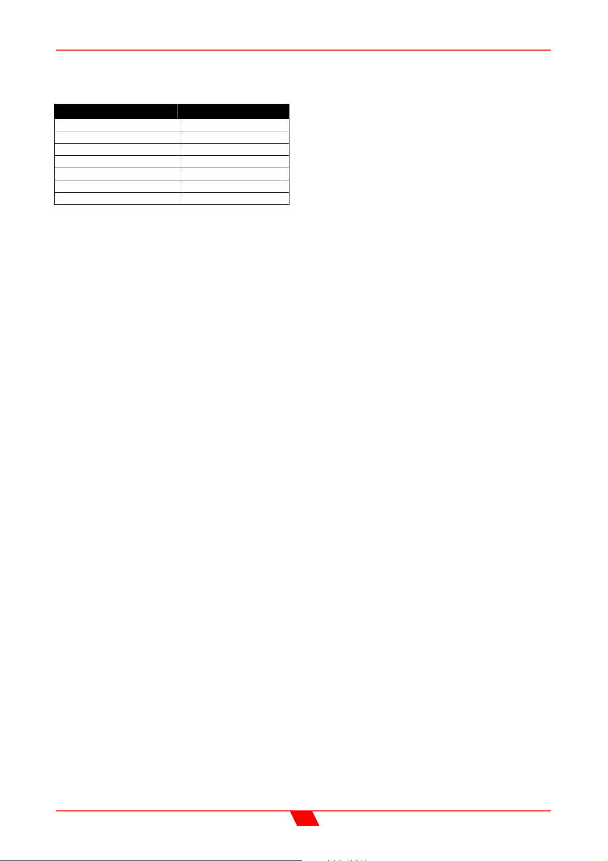
Due the non constant voltage gain of the Proel PRL line of amplifiers (see table at the end
of this section), these presets are valid ONLY if used with the PRL amplifiers specified.
18 AUX + TFL10P BA 2x3 way crossover
Out 1 Aux Out 4 Aux
Out 2 Low Out 5 Low
Out 3 High Out 6 High
Low PRL600, High PRL600
19 AUX + TFL12P BA 2x3 way crossover
Out 1 Aux Out 4 Aux
Out 2 Low Out 5 Low
Out 3 High Out 6 High
Low PRL950, High PRL600
20 AUX + TFL15P BA 2x3 way crossover
Out 1 Aux Out 4 Aux
Out 2 Low Out 5 Low
Out 3 High Out 6 High
Low PRL1400, High PRL600
21 AUX + TFL152P BA 2x3 way crossover
Out 1 Aux Out 4 Aux
Out 2 Low Out 5 Low
Out 3 High Out 6 High
Low PRL1400, High PRL600
22 AUX + TFL212P BA 2x3 way crossover
Out 1 Aux Out 4 Aux
Out 2 Low Out 5 Low
Out 3 High Out 6 High
Low PRL1400, High PRL600
39
Page 40
DSO26 User Manual
23 TFL115SP + SAT 2x3 way crossover
Out 1 Sub Out 4 Sub
Out 2 Sat Out 5 Sat
Out 3 Aux Out 6 Aux
Sub PRL1400
24 TFL115SP + 10P BA 2x3 way crossover
Out 1 Sub Out 4 Sub
Out 2 Low Out 5 Low
Out 3 High Out 6 High
Sub PRL1400, Low PRL600, High PRL600
25 TFL115SP + 12P BA 2x3 way crossover
Out 1 Sub Out 4 Sub
Out 2 Low Out 5 Low
Out 3 High Out 6 High
Sub PRL1400, Low PRL950, High PRL600
26 TFL115SP + 15P BA 2x3 way crossover
Out 1 Sub Out 4 Sub
Out 2 Low Out 5 Low
Out 3 High Out 6 High
Sub PRL1400, Low PRL1400, High PRL600
27 TFL118SP + SAT 2x3 way crossover
Out 1 Sub Out 4 Sub
Out 2 Sat Out 5 Sat
Out 3 Aux Out 6 Aux
Sub PRL1400
28 TFL118SP + 10P BA 2x3 way crossover
Out 1 Sub Out 4 Sub
Out 2 Low Out 5 Low
Out 3 High Out 6 High
Sub PRL1400, Low PRL600, High PRL600
29 TFL118SP + 12P BA 2x3 way crossover
Out 1 Sub Out 4 Sub
Out 2 Low Out 5 Low
Out 3 High Out 6 High
Sub PRL1400, Low PRL950, High PRL600
30 TFL115SP + 15P BA 2x3 way crossover
Out 1 Sub Out 4 Sub
Out 2 Low Out 5 Low
Out 3 High Out 6 High
Sub PRL1400, Low PRL1400, High PRL600
31 TFL115SP + 152P BA 2x3 way crossover
Out 1 Sub Out 4 Sub
Out 2 Low Out 5 Low
Out 3 High Out 6 High
Sub PRL1400, Low PRL1400, High PRL600
40
Page 41

DSO26 User Manual
32 TFL215SP + SAT 2x3 way crossover
Out 1 Sub Out 4 Sub
Out 2 Sat Out 5 Sat
Out 3 Aux Out 6 Aux
Sub PRL950 bridged
33 TFL215SP + 12P BA 2x3 way crossover
Out 1 Sub Out 4 Sub
Out 2 Low Out 5 Low
Out 3 High Out 6 High
Sub PRL950 bridged, Low PRL950, High PRL600
34 TFL215SP + 15P BA 2x3 way crossover
Out 1 Sub Out 4 Sub
Out 2 Low Out 5 Low
Out 3 High Out 6 High
Sub PRL950 bridged, Low PRL1400, High PRL600
35 TFL215SP + 152P BA 2x3 way crossover
Out 1 Sub Out 4 Sub
Out 2 Low Out 5 Low
Out 3 High Out 6 High
Sub PRL950 bridged, Low PRL1400, High PRL600
36 TFL215SP + 212P BA 2x3 way crossover
Out 1 Sub Out 4 Sub
Out 2 Low Out 5 Low
Out 3 High Out 6 High
Sub PRL950 bridged, Low PRL1400, High PRL600
37 TFL218SP + SAT 2x3 way crossover
Out 1 Sub Out 4 Sub
Out 2 Sat Out 5 Sat
Out 3 Aux Out 6 Aux
Sub PRL1400 bridged
38 TFL218SP + 15P BA 2x3 way crossover
Out 1 Sub Out 4 Sub
Out 2 Low Out 5 Low
Out 3 High Out 6 High
Sub PRL1400 bridged, Low PRL1400, High PRL600
39 TFL218SP + 152P BA 2x3 way crossover
Out 1 Sub Out 4 Sub
Out 2 Low Out 5 Low
Out 3 High Out 6 High
Sub PRL1400 bridged, Low PRL1400, High PRL600
40 TFL218SP + 212P BA 2x3 way crossover
Out 1 Sub Out 4 Sub
Out 2 Low Out 5 Low
Out 3 High Out 6 High
Sub PRL1400 bridged, Low PRL1400, High PRL600
41
Page 42
DSO26 User Manual
Voltage gain of TFL amplifiers
Amplifier Voltage gain [dB]
PRL250 30
PRL600 33
PRL950 36
PRL1400 37
PRL600 bridged 39
PRL950 bridged 41
PRL1400 bridged 43
42
Page 43

DSO26 User Manual
SPECIFICATIONS
Inputs: 2 electronically balanced
Impedance: > 10k ohms.
CMRR : >65dB 50Hz - 10kHz.
Outputs: 6 electronically balanced
Source Imp: < 60ohms
Min. Load: 600ohm
Max. Level: +20dBm into 600 ohm
Frequency Resp.:+½dB 20Hz-20kHz
Dyn Range:>110dB 20Hz-20k unwtd
Distortion:< .02%@1kHz,+18dBm
Maximum Delay: 650 mS
Min Step Size: 2.6 µS
Input Gain: +6dB to -40dB in 0.1dB steps
Output Gain: +15dB to -40dB in 0.1dB
steps and mute
Parametric Equalisation
5 Sections per Output
Filter Gain: +15dB to -30dB in 0.1dB
steps.
Freq. Range: 20Hz - 20kHz, 1/36 octave
steps. (368 positions)
Filter Q / BW: 0.4 to 128 / 2.5 to 0.008
(Sections switched to shelving response)
Low frequency: 20Hz - 1kHz
High frequency: 1kHz - 20kHz
Shelf gains: ±15dB in 0.1dB steps.
Options = Transformers available.
Optional Interfaces AES/EBU Digital Input/Output
Due to continuing product improvement the above specifications are subject to change.
High and Lowpass Filters
Filters: 1 of each per output.
Freq. Range HPF: 10Hz - 16kHz
1/36 octave steps.
Freq. Range LPF: 35Hz - 22kHz
1/36 octave steps.
Responses:
Bessel/Butterworth 12-18-24dB/Oct.
Linkwitz-Riley 24dB/Oct.
Limiters
Threshold: +22dBu to -10dBu
Attack time: 0.3 to 90 milliseconds
Release time: 2/4/8/16/32 x Attack time
Display:2x20 character backlit LCD
Input meter: 2 x 3 point
Output meter: 6 x 3 point
Connectors
Inputs: 3 pin female XLR
Outputs: 3 pin male XLR.
External: 9 pin DEE connector (RS232)
Power: 3 pin IEC
Power: 60 to 250V ±15% @ 50/60Hz.
Consumption: < 20 watts.
Weight: 3.5kg. Net (4.8kg. Shipping)
Size: 1.75"(1U) x 19" x 11.8"
(44 x 482 x 300mm) excluding connectors
43
Page 44
DSO26 User Manual
Warranty
This product is warranted against defects in components and workmanship only, for a
period of one year from the date of shipment to the end user. During the warranty period,
Proel will, at it's discretion, either repair or replace products which prove to be defective,
provided that the product is returned, shipping prepaid, to an authorised Proel service
facility.
Defects caused by unauthorised modifications, misuse, negligence, act of God or accident,
or any use of this product that is not in accordance with the instructions provided by Proel,
are not covered by this warranty.
This warranty is exclusive and no other warranty is expressed or implied. Proel is not liable
for consequential damages.
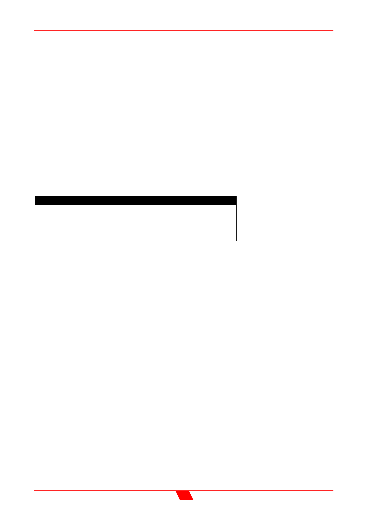
Options and Accessories
Part Description
DSO26 Transformer balanced inputs (factory fitted only)
DSO26 Transformer balanced outputs (factory fitted only)
AES/EBU Digital inputs/outputs (factory fitted only)
9 pin ‘D’ type to 9 pin ‘D’ type cable. (1m)
44
Page 45
DSO26 User Manual
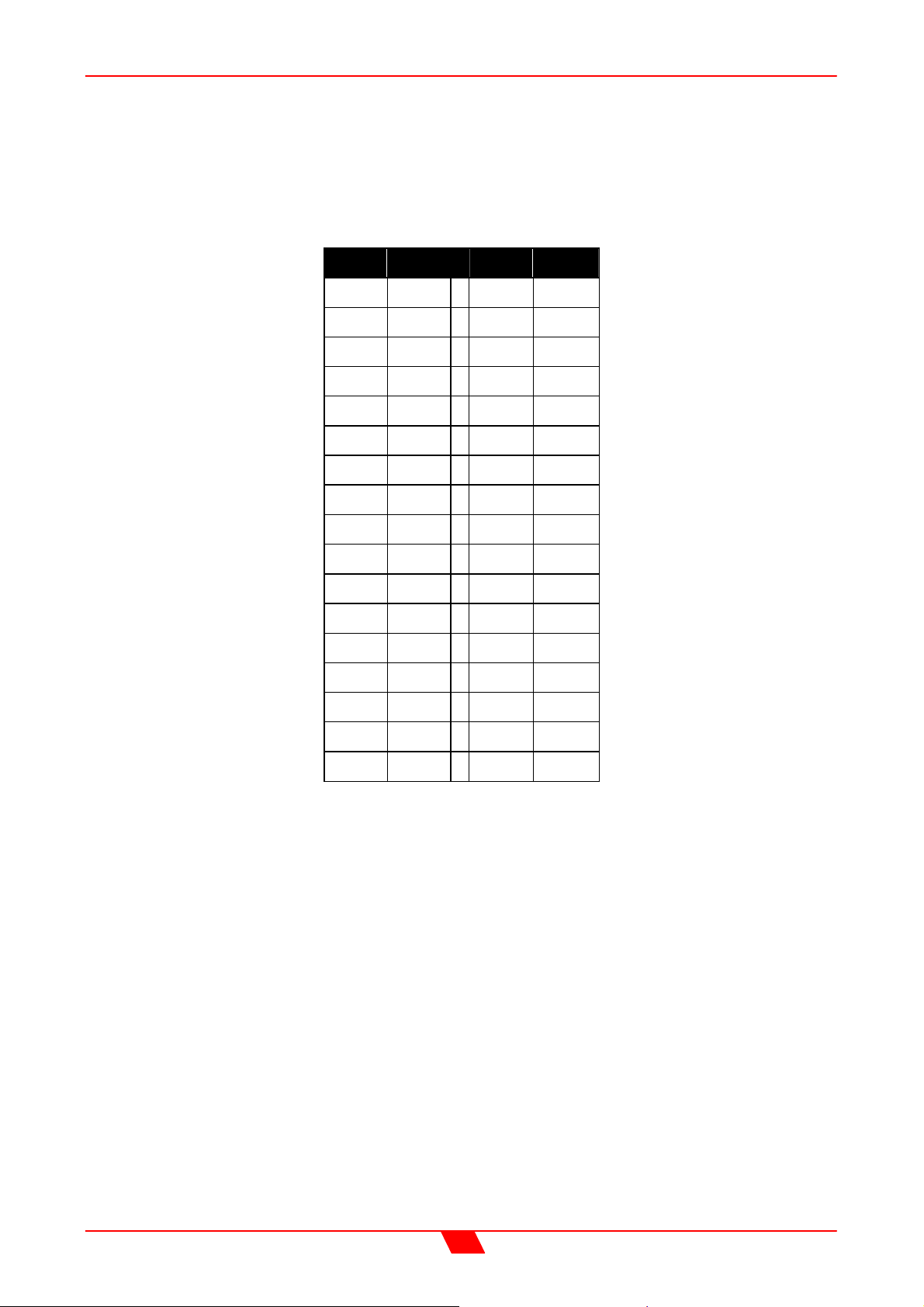
APPENDICES
Appendix 1: Limiter threshold in dB to Vrms lookup table.
dB Vrms dB Vrms
+22 9.75 +5 1.38
+21 8.69 +4 1.23
+20 7.75 +3 1.09
+19 6.90 +2 0.98
+18 6.15 +1 0.87
+17 5.48 0 0.77
+16 4.89 -1 0.69
+15 4.36 -2 0.62
+14 3.88 -3 0.55
+13 3.46 -4 0.49
+12 3.08 -5 0.44
+11 2.75 -6 0.39
+10 2.45 -7 0.35
+9 2.18 -8 0.31
+8 1.95 -9 0.27
+7 1.73 -10 0.24
+6 1.55
Calculation:
Vrms = 0.7746 x 10 ^ (dBu + 20)
45
Page 46
DSO26 User Manual
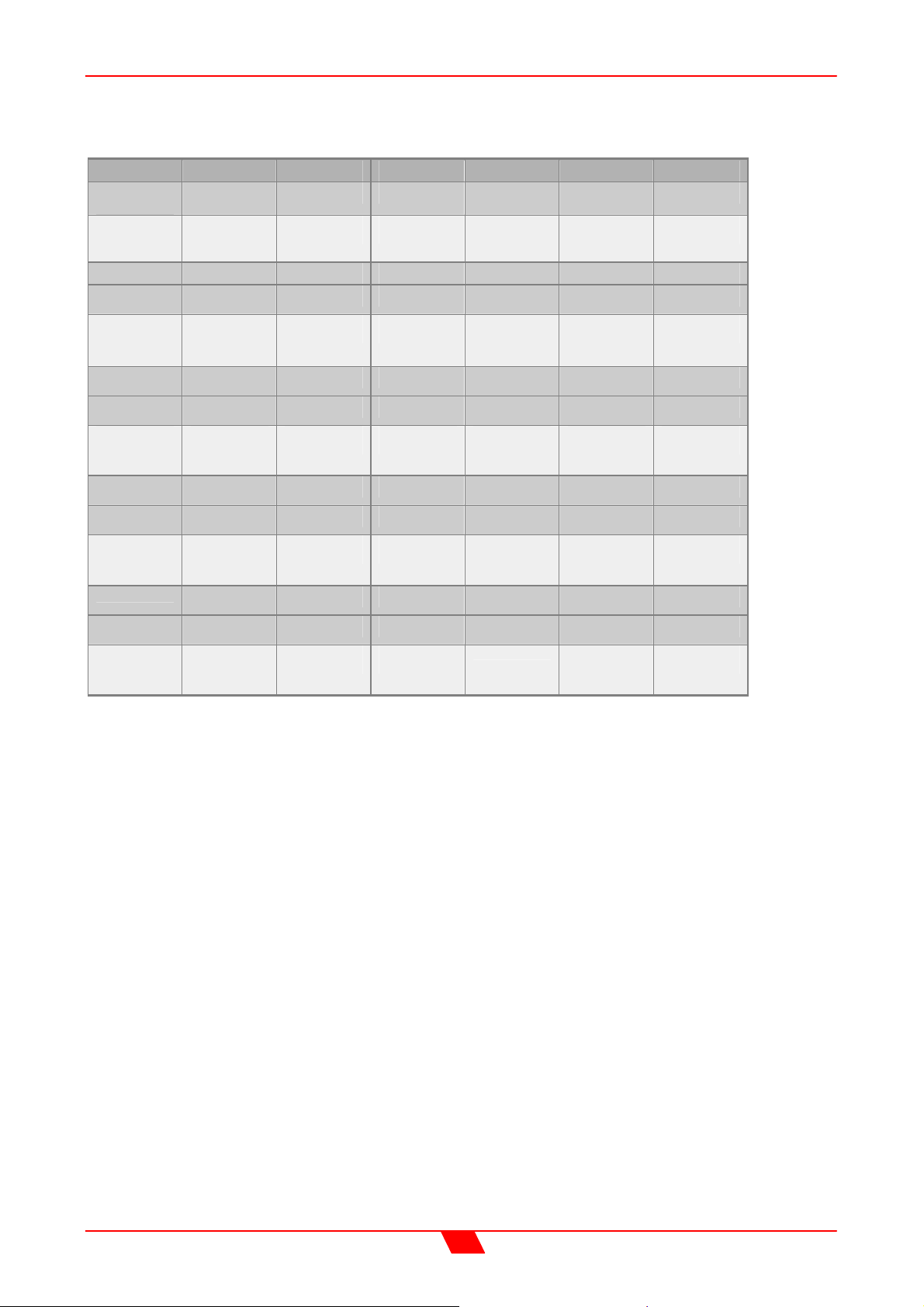
Appendix 2: Default X-over settings and names for all formats.
X-over Output 1 Output 2 Output 3 Output 4 Output 5 Output 6
2x2
way+Ms
Low High Low High Msub Aux
120Hz –
1k82Hz
1k82Hz –
22kHz
120Hz –
1k82Hz
1k82Hz –
22kHz
24.8Hz –
120Hz
<10Hz –
22kHz
2 x 3 way
4 way + 2
5 way + 1
6 way
Low Mid High Low Mid High
22.1Hz –
120Hz
120Hz –
1k82Hz
1k82Hz –
22kHz
Low LoMid HiMid High Aux Aux
15Hz –
149Hz
149Hz –
1k31Hz
1k31Hz –
8kHz
Sub Low LoMid HiMid High Aux
15Hz –
80.3Hz
80.3Hz –
180Hz
180Hz –
1k31Hz
LoSub Sub Low LoMid HiMid High
15Hz –
80.3Hz
80.3Hz –
149Hz
149Hz –
1kHz
Note: All filters set to 24dB Linkwitz-Riley.
22.1Hz –
120Hz
8kHz – 22kHz 20.1Hz –
1k31Hz –
8kHz
1kHz – 4kHz 4kHz –
120Hz –
1k82Hz
22kHz
8kHz – 22kHz 20.1Hz –
10k1Hz
1k82Hz –
22kHz
20.1Hz –
22kHz
22kHz
10k1Hz –
22kHz
46
Page 47
DSO26 User Manual
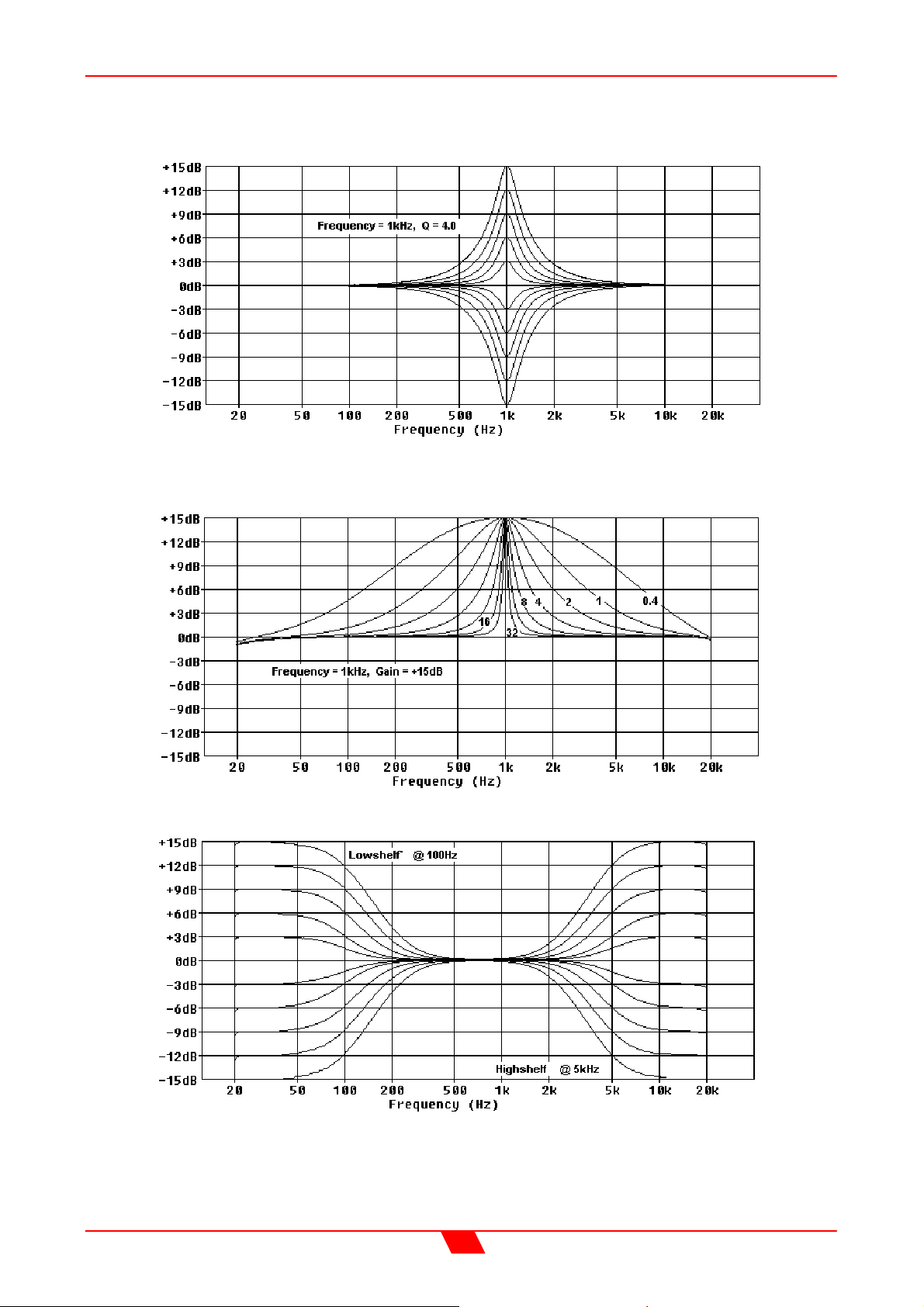
Appendix 3: Equalisation Curves
Parametric Filter Gain Curves
Parametric Filter ‘Q’ Curves
Parametric Filter High and Low Shelving Responses
47
Page 48
DSO26 User Manual
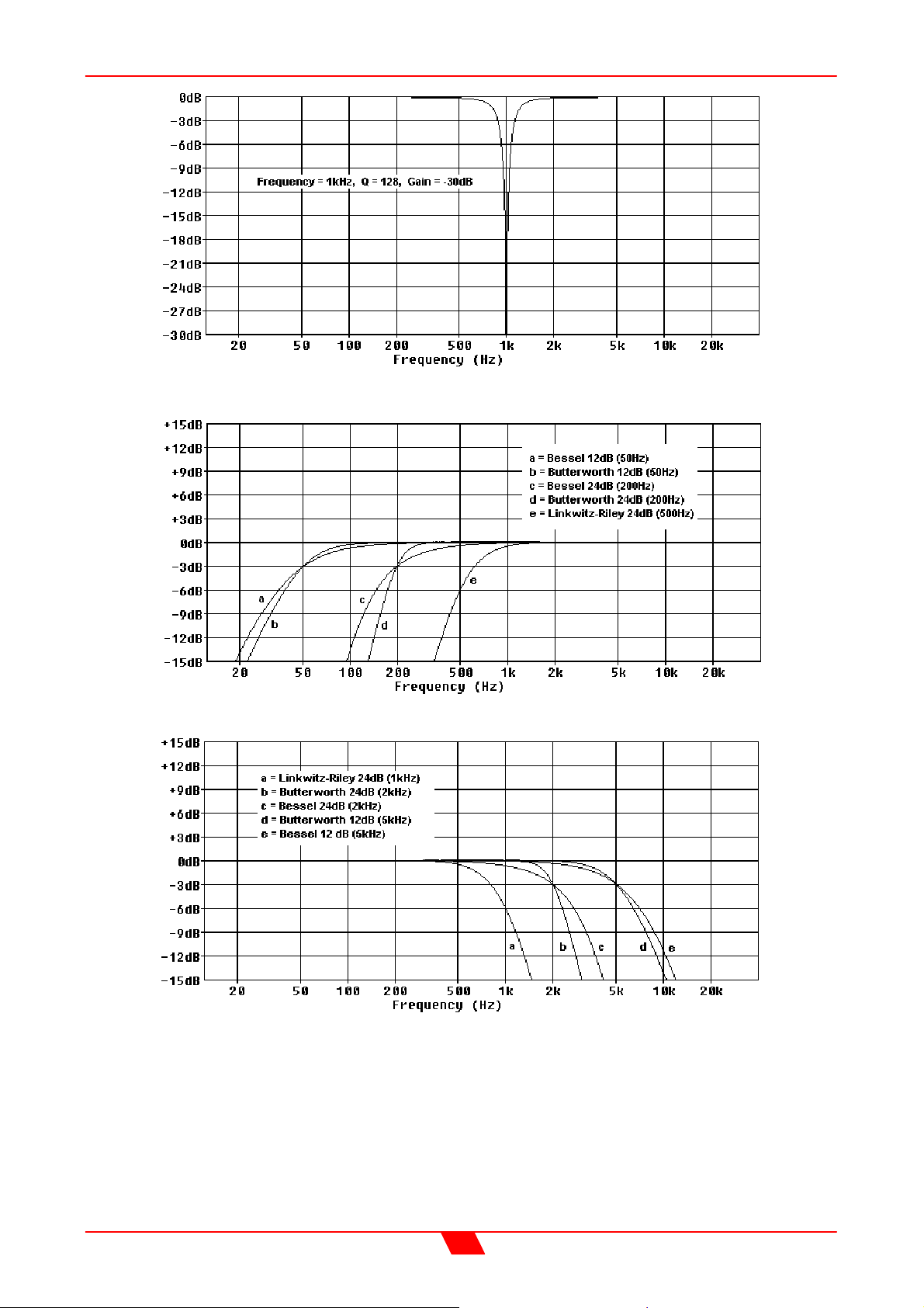
Parametric Filter High ‘Q’ – Notch Filter Response
High Pass Filter Response Curves
Low Pass Filter Response Curves
48
Page 49

Page 50

PROEL S.p.A.
(World Headquarters – Factory)
Via alla Ruenia, 37/43
64027 Sant’Omero (TE) – Italy
Tel: +39.0861.81241
Fax: +39.0861.887862
E-mail: [email protected]
www.proelgroup.com
 Loading...