

MANUALE UTENTE - INSTRUCTION MANUAL
Sistema conferenza – Conference system
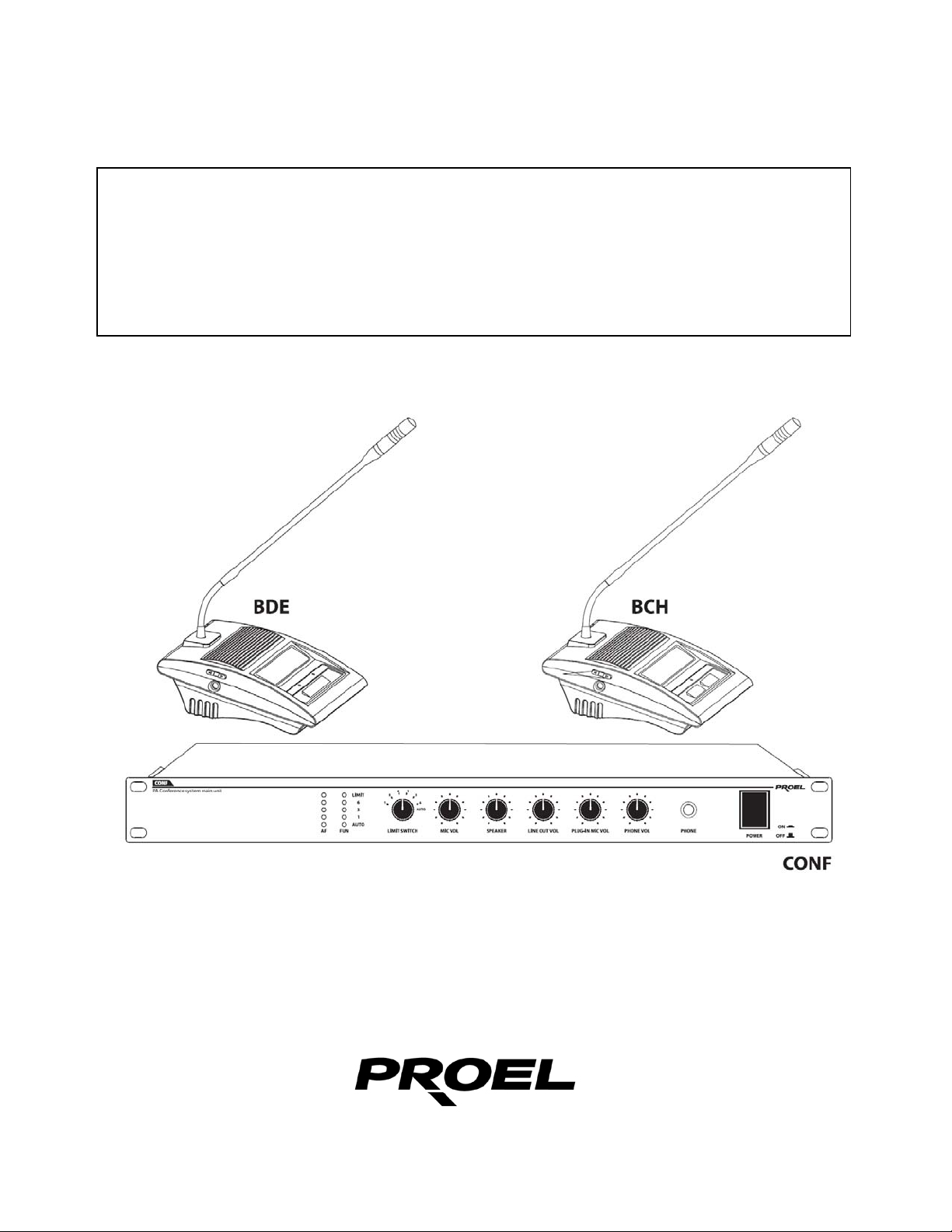
CONF - BCH - BDE

1. PRECAUZIONI D’USO
AVVERTENZA:
ATTENZIONE:
Questo simbolo, ove compare, segnala la presenza di un voltaggio pericoloso
Questo simbolo, ove appare, segnala, importanti istruzioni d’uso e
RACCOMANDAZIONI:
Tutte le istruzioni di sicurezza e funzionamento devono essere lette prima di mettere in funzione
l’apparecchio.
Conservare le istruzioni:
Le istruzioni di sicurezza e di funzionamento devono essere conservate per un futuro riferimento.
Il presente manuale è parte integrante del prodotto e lo deve accompagnare in caso di eventuali
cambi di proprietà. In questo modo il nuovo proprietario potrà conoscere le istruzioni relative a
installazione, funzionamento e sicurezza.
Prestare attenzione:
Tutte le avvertenze sull’apparecchio e nelle istruzioni di funzionamento devono essere seguite
fedelmente
Osservare tutti gli avvertimenti.
Seguire le istruzioni:
Tutte le istruzioni per il funzionamento e per l’utente devono essere seguite.
.
Per ridurre il rischio di folgorazione, non rimuovere il coperchio (o il pannello
posteriore). All’interno non sono contenute parti riparabili dall’utente; affidare
la riparazione a personale qualificato.
Per ridurre il rischio d’incendio o di folgorazione, non esporre questo
apparecchio alla pioggia o all’umidità.
non isolato all’interno del corpo dell’apparecchio – voltaggio sufficiente a
costituire un rischio di folgorazione.
manutenzione nel testo allegato. Leggere il manuale
.

Le note precedute dal sim bolo contengono importanti informazioni sulla sicurezza:
leggerle con particolare attenzione.
ISTRUZIONI DI SICUREZZA IN DETTAGLIO.
Acqua ed umidità:
L’apparecchio non deve essere utilizzato in prossimità di acqua (per es. vicino a vasche da
bagno, lavelli da cucina, in prossimità di piscine ecc.).
Ventilazione
L’apparecchio deve essere posto in modo tale che la sua collocazione o posizione non
interferisca con l’adeguata ventilazione. Per esempio, l’apparecchio non deve essere
collocato su un letto, copri-divano, o superfici simili che possono bloccare le aperture di
ventilazione, o posto in una installazione ad incasso, come una libreria o un armadietto che
possono impedire il flusso d’aria attraverso le aperture di ventilazione.
Calore:
L’apparecchio deve es sere p osto lontano d a fonti d i calo re com e radiatori, term ostati, asciuga
biancheria, o altri apparecchi che producono calore.
Alimentazione:
• L’apparecchio deve essere collegato soltanto al tipo di alimentazione descritto nelle
• Se la spina in dotazione non combacia con la presa, rivolgersi ad un elettricista per farsi
Messa a terra o polarizzazione:
• Si devono prendere precauzioni in modo tale che la messa a terra e la polarizzazione
• Le parti metalliche dell’apparecchiatura sono collegate a massa tramite il cavo
• Se la pre sa utilizzata per alimentazione non possiede collegamento a massa, rivolgersi
Protezione del cavo di alimentazione:
Il cavo di alimentazione elettrica deve essere installato in modo che non venga calpestato o
pizzicato da oggetti posti sopra o contro, prestando particolare attenzione a cavi e spine,
prese a muro.
Pulizia:
• Quando l’unità deve essere pulita, è possibile eliminare la polvere utilizzando un getto
• Non pulire l’unità utilizzando solventi quali trielina, diluenti per vernici, fluidi, alcol, fluidi ad
Periodi di non utilizzo:
Il cavo di alimentazione dell’apparecchio deve essere staccato dalla presa se rimane
inutilizzato per un lungo periodo.
:
istruzioni d’uso o segnalato sull’apparecchio.
installare una presa appropriata.
dell’ apparecchio non siano pregiudicate.
d’alimentazione.
ad un elettricista qualificato per fare collegare l’apparato a massa tramite il terminale.
d’aria compressa o un panno inumidito.
alta volatilità o altri liquidi infiammabili.

Ingresso di liquidi o oggetti:
Si deve prestare attenzione che non cadano oggetti e non si versino liquidi nel corpo
dell’apparecchio attraverso le griglie.
Uso sicuro della linea d’alimentazione:
• Quando si scollega l’apparato alla rete tenere saldamente sia la spina che la presa.
• Quando l’unità non viene utilizzata per un periodo prolungato, interrompere
l’alimentazione estraendo la spina dalla presa dell’alimentazione
• Per evitare danni alla linea d’alimentazione dell’apparato, non mettere in trazione il cavo
d’alimentazione e non utilizzare un cavo attorcigliato.
Per evitare il danneggiamento del cavo d’alimentazione dell’apparato, assicurarsi che
•
questo non venga calpestato o schiacciato da oggetti pesanti.
Spostamento dell’unità:
Prima di ogni spostamento, verificare che l’unità sia spenta. Il cavo d’alimentazione deve
essere estratto dalla presa, così come i collegamenti dell’unità con altre linee.
Non smontare l’unità:
Non tentare di smontare né riparare da soli l’unità. Per qualsiasi problema non risolvibile con
l’aiuto del presente manuale, rivolgersi a un tecnico qualificato o consultare la nostra
compagnia. Qualsiasi uso non appropriato può causare incendi o scosse elettriche.
Malfunzionamenti:
• Non tentare mai di eseguire riparazioni diverse da quelle descritte nel presente manuale.
• Contattare un centro di servizio autorizzato o del personale altamente qualificato nei
seguenti casi:
- Quando l’apparato non funziona o funziona in modo anomalo.
- Se il cavo d’alimentazione o la spina sono danneggiati.
- Sono penetrati oggetti estranei o è stato versato del liquido nell’apparecchio.
- L’apparecchio è stato esposto alla pioggia.
- L’apparecchio non sembra funzionare normalmente o presenta un evidente
cambiamento nelle prestazioni.
- L’apparecchio è caduto, o il corpo è danneggiato.
Manutenzione:
L’utente non deve tentare di riparare l’apparecchio al di là di quanto descritto nelle istruzioni di
funzionamento. Ogni altra riparazione deve essere affidata a personale specializzato.
IMPORTANTI NORME DI SICUREZZA:
• Installare seguendo le istruzioni.
• Il voltaggio d’alimentazione dell’unità è abbastanza elevato per evitare il rischio di scosse
elettriche, non installare, collegare o sconnettere l’alimentazione quando l’apparato è
acceso.
• Non aprire mai l’apparecchiatura: all’interno non esistono parti utilizzabili dall’utente.
• Se si avverte uno strano odore proveniente dall’apparato, spegnerlo immediatamente e
sconnettere il cavo dell’ ali m en taz io ne .
• Non ostruire le griglie di ventilazione dell’apparato.
• Evitare che l’unità lavori in sovraccarico per tempo prolungato.
• Non forzar e i c omandi (pulsanti, control l i , ec c.)

• Avvitare completamente i terminali a vite degli altoparlanti per garantire la sicurezza dei
contatti.
•
• Utilizzare unicamente i connettori e gi accessori specificati dal produttore.
•
• In presenza di temporali con fulmini o quando l’apparato non è utilizzato, estrarre la spina
•
• PROEL S.P.A. declina ogni responsabilità in caso di scorretta installazione dell’unità.
Per ragioni di sicurezza, non annullare il collegamento a massa della spina. Il
collegamento a massa è necessario per salvag uardare la sicurezza dell’operatore
L’apparato deve essere collocato in un rack metallico (vedi INSTALLAZIONE) e tenuto
lontano da:
Luoghi umidi
Esposizione diretta a fonti di calore (come luce solare).
Luoghi non sufficientemente ventilati
d’alimentazione dalla presa.
Per prevenire il rischio di incendi e scos se elettriche, è necessario tene re l’apparat o
lontano da spruzzi e gocce. Sopra l’apparato non devono essere collocati vasi o altri
oggetti contenenti liquidi. In caso si verifichino interferenze nel circuito di provenienza, il
valore di THD sarà superiore al 10%. Non installare questo apparato in una libreria o in
altri luoghi a spazio ristretto

Grazie per aver scelto un prodotto Proel e della fiducia riposta nel nostro
marchio, sinonimo di professionalità, accuratezza, elevata qualità ed affidabilità.
Tutti i nostri prodotti sono conformi alle normative CE per utilizzazione continua
in impianti di diffusione sonora.
2. DESCRIZIONE
Il Sistema di conferenza e discussione è composto dall’unità principale
denominata CONF, dalle unità microfoniche Delegato (BDE) e Presidente
(BCH) caratterizzate da un’elevata sensibilità, da un’ampia risposta in
frequenza e dotate di microfono cardioide elettrete con anello luminoso per una
facile identificazione del microfono abilitato. Il sistema è dotato di cavi precablati
che ne rendono l’installazione estremamente semplice e flessibile.
L’impianto potrà essere composto da un massimo di 45 basi microfoniche (44
basi Delegato + 1 base Presidente), interconnesse fra loro in cascata su tre
BUS di connessioni indipendenti (in ogni caso non superare mai le 15 unità per
ogni linea). Il collegamento in serie delle postazioni si realizza tramite singoli
cavi multipolari preintestati, adatti per l’allestimento di sistemi sia mobili che
fissi.
funzioni principali:
Alimentazione e controllo diretto di n° 45 unità microfoniche.
•
Base presidente con priorità
•
Tre modalità operative degli interventi: 1 - 3 o 6 postazioni attive in
•
contemporanea.
Funzione AUTO
•
Ingressi di segnale MICRO e LINEA per unità esterne.
•
Uscite TAPE per registrazione e LINEA per amplificazione di sala.
•
Uscita cuffia con controllo di livello per monitoraggio.
•
Controllo livello sensibilità microfoni.
•
Controllo livello altoparlanti monitor delle unità.
•
Prodotto conforme alla normativa CE
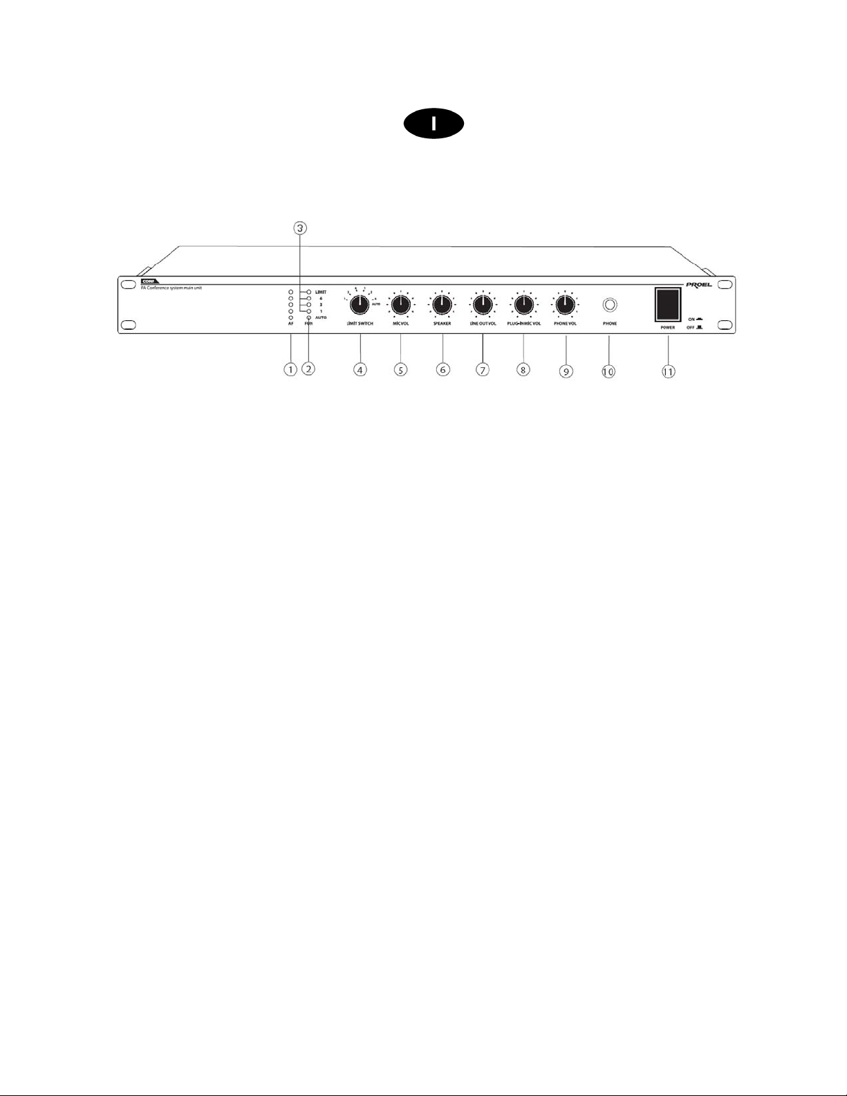
3. FUNZIONI E CONTROLLI PANNELLO FRONTALE
1. Indicatore livello AF
indica l’intensità del segnale audio
2. Indicatore AUTO
Quando la funzione AUTO è attiva la spia led è accesa. In questa
condizione, se una base microfonica non riceve il segnale audio per
più di 1 minuto, viene automaticamente disattivat a.
3. Indicatori
Led 1 ON: è abilitato un solo microfono alla volta
Led 3
contemporaneamente
Led 6
contemporaneamente
ON: possono funzionare al massimo 3 microfoni
ON: possono funzionare al massimo 6 microfoni
fig.1
Led LIMIT ad ON: il sistema ha raggiunto la quantità
massima dei microfoni abilitati
4. LIMIT SWITCH
Ruotando questo selettore impostiamo il numero di microfoni (1-3 o 6)
che possono funzionare contemporaneamente. Le prime 3 posizioni
limitano il numero di microfoni in modalità NORMALE, mentre le
restanti tre in modalità AUTOMATICA.
Nota: In modalità automatica (AUTO) quando la postazione
microfonica non riceve il segnale audio per piu’ di 1 minuto, si disattiva
automaticamente.
5. MIC VOL
Regola il livello audio dei microfoni delle postazioni
6. SPEAKER
Regola il livello audio dell’altoparlante monitor delle post azioni
7. LINE OUT VOL
Regola il livello sull’uscita LINE OUT
8. PLUG IN MIC VOL
Regola il livello del microfono esterno
9. PHONE VOL
Regola il livello dell’uscita cuffia
10. PHONE
Connessione cuffia (jack 6,3 mm)
11. POWER
Interruttore principale
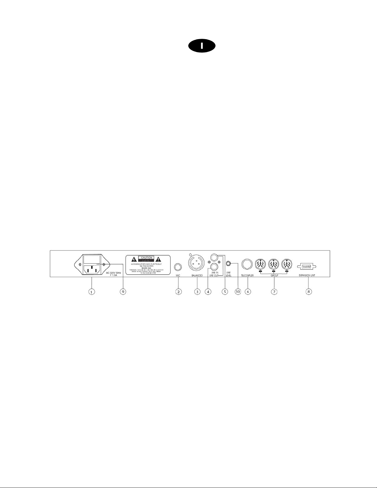
4. FUNZIONI E CONTROLLI PANNELLO POSTERIORE
1. Ingresso per l’alimentazione di rete
230Vac / 50Hz
2. MIC
Ingresso microfonico bilanciato (Jack stereo 6,3)
3. Uscita di segnale bilanciata
Collegare a quest’uscita il mixer o l’amplificatore di sala
4. LINE IN
Ingresso a livello linea. Collegare a quest’ingresso una sorgente audio
tipo lettori CD ecc.
5. LINE OUT
Uscita sbilanciata a livello linea. Per registrare la conferenza collegare
a quest’uscita un registratore
6. COUPLER TELEFONICO
Disponibile per applicazioni future
(RCA)
(XLR3)
fig.2

7. GROUP
N° 3 ingressi per unità Presidente/Delegato. Ad ogni linea può essere
collegato un numero massimo di 15 unità (non superare questa
quantità) per un totale di 44 delegati e 1 presidente
8. EXPANSION UNIT
Disponibile per applicazioni future
9. Fusibile
alloggio per fusibile da 1,5A
10. LINE LEVEL
Regola il livello del segnale sull’ingress o LI NE IN
5. FUNZIONI E CONTROLLI UNITA’ DELEGATO (BDE)
fig.3
1. Capsula microfonica
2. Anello luminoso
3. Comando di regolazione del volume altoparlante monitor
4. Ingresso cuffia (jack stereo 3,5 mm)
5. MIC
Se il limite massimo di basi che funzionano contemporaneamente alla
conferenza non è stato raggiunto, premendo questo tasto si è abilitati
a parlare
6. Altoparlante monitor

6. FUNZIONI E CONTROLLI UNITA’ PRESIDENTE (BCH)
1. Capsula microfonica
2. Anello luminoso
3. Comando di regolazione del volume altoparlante monitor
4. Ingresso cuffia (jack stereo 3,5 mm)
5. MIC
Se il limite massimo di basi che funzionano contemporaneamente alla
conferenza non è stato raggiunto, premendo questo tasto si è abilitati
a parlare
6. PRIORITY
Mediante la pressione di questo tasto il Presidente toglie la parola a
tutte le unità in funzione
7. Altoparlante monitor
fig.4
7. Collegamenti
Collegare la presa di alimentazione alla rete 230VAC, utilizzando i cavi di
connessione a corredo collegare ai 3 ingressi
in cascata (come riportato in fig.5) avendo l’accortezza di collegare un massimo
di 15 postazioni per ogni linea. Il sistema gestisce un'unica base Presidente che
può essere inserita in una qualsiasi posizione della catena.
GROUP (fig.2 rif.7
) le postazioni

Se i cavi in dotazione non dovessero essere sufficienti è possibile utilizzare le
prolunghe
CV3, CV5
e
CV10
(opzionali).
TIPO DI CONNESSIONI
Connessione di tipo bilanciata:
fig.5

Connessione di tipo sbilanciata:
Connessione di tipo bilanciata con jack stereo
Connessione di tipo sbilanciata con jack stereo
Connessione Bilanciata su morsetto EUROBLOC
Connessione Sbilanciata su morsetto EUROBLOC
Connessione RCA

8. Come utilizzare il sistema
Accendere l’unità
CONF
, l’indicatore luminoso (
fig1. rif.11
) indicherà il numero
di basi che possono funzionare contemporaneamente a seconda della scelta
effettuata mediante il selettore
LIMIT SWITCH (fig1. rif4
selettore impostare sia la quantità prescelta che il tipo di funzionamento (
), mediante questo
AUTO
o normale), a tale scopo vedere paragrafo 3. Regolare i controlli di volume
Microfoni e diffusori secondo le proprie esigenze. Il sistema è pronto per essere
utilizzato, premendo il tasto MIC (fig.3 rif.5 - fig.4 rif.5) sulla base presidente o
delegato, l’anello luminoso si accende ed è possibile parlare, ad una successiva
pressione del Tasto MIC o dopo un minuto se la funzione AUTO è attiva, il
microfono si spegne. La base Presidente è dotata di tasto
PRIORITY
la cui
pressione porta allo stato OFF tutte le basi delegato che stavano funzionando in
al momento.
9. Specifiche Tecniche
Model CONF
Delegate/Chairman inte rface
Frequency response (-3dB)
S/N Radio
Weight
Dimensions (WxHxD)
8P-DIN sochet / n°3 BUS
100-12,5KHz
>70 dB
2,5Kg
483x44x200
Il prodotto è conforme alla Direttiva 89/336/CEE (Compatibilità Elettromagnetica)
e successive modifiche 92/31/CEE e 93/68/CEE, secondo i seguenti standard:
EN 50082-1:1997, EN 55013:1990 , E N 5502 0 :19 94
inoltre, è conforme alla Direttiva 73/23/CEE (Bassa Tensione)
e successive modifiche 93/68/CEE, secondo il seguente standard:
EN 60065:1998
La Proel SpA persegue una politica di costante ricerca e sviluppo, di conseguenza si riserva il diritto di
apportare miglioramenti ai prodotti esistenti, senza preavviso e in qualunque momento.

1. IMPORTANT SAFETY INSTRUCTIONS
CAUTION:
WARNING:
This symbol is intended to alert the user of the presence of uninsulated
This symbol is intended to alert the user of the presence of important operating
INSTRUCTIONS:
All safety and operating instructions should be read before the product is operated.
Retain these instructions:
All safety and operating instructions should be retained for future reference .
This owner’s manual should be considered as a part of the product and it must accompany it
every time, and delivered to the new user when this product is sold. In this way the new owner will
be aware of all the installations, operating and safety instructions.
Heed all warnings:
All warnings on the product and in owner’s manual should be adhered to.
Heed all warnings.
Follow all instructions:
All operating and user’s instructions must be followed.
To reduce the risk of electric shock do not remove cover (or back panel). No
user serviceable parts inside. Refer servicing to qualified personnel only.
To reduce the risk of fire or electric shock, do not expose this apparatus to
rain or moisture.
dangerous voltage within the product enclosure that may be of sufficient
magnitude to constitute a risk of electric shock to persons.
and maintenance (servicing) instruction in the literature accompanying the
appliance. Please carefully read the owner’s manual.

Sentences preceded by
DETAILED SAFETY INSTRUCTIONS.
Water and moisture:
This apparatus should not be used near water (i.e. bathtub, kitchen sink, swimming pools,
etc.)
Ventilation
This apparatus should be placed in a position that doesn’t interfere with correct ventilation.
This unit, for example, should not be placed on a bed, sofa cover o similar surfaces that could
cover ventilation openings, or placed in a built-in installation, such a bookcase or a cabinet
that could block air flow trough ventilation openings.
Heat:
This apparatus should be placed away from heat sources, like radiators, heat registers, stoves
or other products (including amplifiers) that produce heat.
Power sources:
• This apparatus should be connected only to power source type specified in this owner’s
•
Grounding or Polarization:
• All precautions must be observed in order to avoid grounding or polarization defeating.
• Unit metal parts are grounded through the AC power cord.
• If the AC power outlet doesn’t have grounding, consult an electrician for outlet grounding.
Power cord protection:
The power cord should be routed in a way it will not be walked on or pinched by items placed
upon or against it, paying particular attention to cords at plugs, convenience receptacles and
wall outlet.
Cleaning:
• You can clean the unit with a compressed air flow or a wet cloth.
• Don’t clean the unit using solvents like trichloroethylene, thinners, alcohol, or other fluids
Non use periods:
The unit AC power cord should be unplugged from the outlet if it’s unused for a long period.
:
manual or on the unit.
If the supplied AC power cable plug is different from wall socket, please contact an
electrician to change the AC power plug.
with very strong volatility and flammability.
symbol contain important safety instruction. Please read it carefully.

Objects or liquid entry inside the unit:
Be careful that no objects fall or liquid is spilled inside the unit through ventilation openings.
Safe power line use:
• Keep firmly the plug and the wall outlet while disconnecting the unit from AC power.
• When the unit will not be used for a long period of time, please unplug the power cord
from AC power outlet.
• To avoid unit power cord damages, please don’t strain the AC power cable and don’t
bundle it.
• In order to avoid unit power cord damages, please be sure that the power cord is not
walked on or pinched by heavy objects.
Unit relocation:
Before any unit relocation please control the unit is turned off. The power cord must be
unplugged by the wall outlet, and all the connections wires should be disconnected as well.
Don’t open this unit:
Don’t attempt to open or repair this unit by yourself. For any problem solution not described in
this owner’s manual, please refer to qualified personnel only or consult us or your National
Distributor. Any improper operation could result in fire or electric shock.
Damages requiring services:
• Don’t attempt to do operations not described in this user’s manual.
• In the following cases please refer to an authorized maintenance center or skilled
personnel:
- When the unit works improperly or it doesn’t work at all.
- If power cord or plug are damaged.
- If liquid has spilled, or objects have fallen into the unit.
- The unit has been exposed to rain.
- The unit doesn’t operate normally o it exhibits a marked change in performance.
- If the product has dropped or it has been damaged in any way.
Maintenance:
The user shouldn’t attempt maintenance operation not described in this user’s manual. Every
maintenance operation should be done by qualified personnel only.
IMPORTANT SAFETY INSTRUCTIONS:
• Install this unit following owner’s manual instructions.
• Don’t install, connect or disconnect power supply when the unit is powered, otherwise
there’s an high risk of electric shock.
• Don’t open the unit, there are no user serviceable parts inside.
• If you detect a particular smell from the unit, please immediately turn it off and disconnect
the AC power cord.
• Don’t block the unit ventilation openings.
• Avoid to use this unit in overload for a long period.
• Don’t force commands (switches, controls, etc.)

• To obtain good speakers wire contacts, please tighten the screw terminals firmly.
•
• Use only connectors and accessories suggested by the manufacturer. .
• This unit should be placed in a rack (see INSTALLATION) and kept far from:
• Disconnect the power cord during storms or when the unit is not used.
•
•
For safety reason, don’t defeat the grounding connection. Grounding is useful for user
safety.
Wet places
Direct exposure to heat sources (like sun light)
Non properly ventilated places
In order to prevent fi re and electric shock risks, it ’s necessary to keep the unit far
from sprinkling and drops. Ple ase don’t put cups, vase s or other object contain ing liquids
over the unit. In case of interferences from source signal, THD value will raise over 10%.
Don’t place this unit in a bookshelf o in other places with small room.
PROEL S.P.A. is not responsible for any damage that occurs due to a wrong unit
installation.

Thank you for choosing one of Proel products, and for your confidence towards
our brand, synonymous of professionalism, accuracy, high quality and reliability.
All our products are CE approved and designed for continuous use in
professional i n stallation systems.
2. DESCRIPTION
Proel system for conference and discussion is composed by the main central
unit CONF, delegate microphone stand unit (BDE) and the chairman stand unit
(BCH). The microphone stands units are high sensibility characterized and are
electret cardioide microphone equipped. Each microphone stand unit is with a
lighting ring to allow to the user to individuate the activation s tatus. The system
is supplied with pre-wired cables for an “ easy plug and play” purposes.
Proel conference system configuration involves up to a maximum of 45
microphone stands (44 Delegate stands + 1 Chairman stand). Interconnection
in cascade on 3 independent connections BUS (do never over 15 stands units
per BUS). The serial connection is to be effected by single multi-pole cable
suitable for both temporary or fixed installation.
Main functions:
Direct control and power supply for 45 microphone st ands.
•
Chairman microphone stand with priority purposes.
•
3 interventions operating mode: 1- 3 or 6 microphone stands
•
contemporaneous activation
AUTO operatine mode
•
MICRO and LINE signal inputs for external units.
•
TAPE and LINE outputs for recording and ambient sound reinforcement
•
purposes.
Headphone output with monitoring level control.
•
Microphone sensibility level control.
•
Loudspeaker monitor unit level control.
•
Product in compliance with
standards
CE

3. FUNCTIONS AND FRONT PANEL CONTROLS
1. AF level indicator
For audio signal intensity level indication
2. AUTO indicator
When AUTO function is activated, the led is ON status. In this case
and if for more d’un one minute there is no audio signal on one of the
microphone stands of the configuration, AUTO function is disabled
automatically.
3. Indicators
fig.1
Led 1
Led 3 ON: a maximum of 3 microphones can be
activated contemporaneously
Led 6
activated contemporaneously
Led LIMIT ad ON: the system has reached the
maximum number of microphones to be activated
contemporaneously
4. LIMIT SWITCH
Throughout such selector rotation, the number of microphones
contemporaneous activation can be set (1-3 o 6). The fir st 3 p osition s
limit the number of microphones in NORMALE MODE whilst the
remaining 3 positions limit the number of microph one in AUTOMATIC
MODE.
Nota: AUTO mode is disabled when for one of the microphone stand
for one minute there is no Audio Signal
ON: only one microphone per time is abled
ON: a maximum of 6 microphones can be

5. MIC VOL
For microphone stand audio level cont rol
6. SPEAKER
For stand monitor loudspeaker audio level control
7. LINE OUT VOL
Output LINE OUT level control
8. PLUG IN MIC VOL
External microphone level control
9. PHONE VOL
For headphone output level control
10. PHONE
Headphone Connection (jack 6,3 mm)
11. POWER
Main power switch
4. FUNCTIONS AND CONTROL FOR REAR PANEL
1. Main power supply input 230Vac / 50Hz
2. MIC
Microphone balanced input (Ja ck stereo 6, 3)
3. Balanced signal output
For mixer/amplifier connection
4. LINE IN
Line level input. For audio sources (CD player,Mp3 etc..) connection.
5. LINE OUT (RCA)
Unbalanced line level output. For recording purposes connections
6. COUPLER TELEFONICO
Available for future Proel conference system up grade
(XLR3)
fig.2

7. GROUP
N° 3 inputs for chairman/delegates microphone stands. Up to 15
microphone stands can be connected to each line ( do never exceed
such number of units) for a total of 44 delegate stands and one
chairman.
8. EXPANSION UNIT
Available with future system up grade
9. Fusibile
Fuse of 1,5 a compartment
10. LINE LEVEL
LINE IN Signal level control
5. FUNCTIONS AND CONTROLS FOR DELEGATE MICROPHONE
STAND (BDE)
fig. 3
1. Microphone capsule
2. lighting ring
3. key for loudspeaker mo nitor volume control
4. Headphone input (ja ck stereo 3,5 mm)
5. MIC
Press such key to enable the microphone stand when the maximum
number of microphone stands activated contemporaneously is not
reached
6. Monitor loudspeaker

6. FUNCTIONS AND CHAIRMAN STAND CONTROLS (BCH)
1. Microphone capsule
2. Lighting ring
3. Monitor loudspeaker volume control
4. Headphone input (ja ck stereo 3,5 mm)
5. MIC
Press such key to enable the microphone stand when the maximum
number of operating microphone stands contemporaneously is not
reached.
6. PRIORITY
Pressing such key all the microphone stands involved by the
configuration are disable
7. Monitor loudspeaker
fig.4
7. Connections
Connect the main power plug to the main power supply voltage 230VAC, using
the connection cables included in the standard package to the 3
(fig. 2 ref .7) in cascade ( revert to fig.5). Do not exceed 15 microphone stands
per line. The present conference system can manage only one chairman
microphone sand to be inserted -in a free way- in th e microphone stands chain
GROUP
inputs

In case the cables included in the supply are not sufficient, it is possible to
consider optional extension cables referred respectively
CV5
(
five meters length
) and
CV10
(
10 meters length
).
CV3
3 meters length)
(
CONNECTIONS TYPE
Balanced connection:
fig.5

Unbalanced connections:
Balanced connection with jack stereo
Unbalanced connection with jack stereo
Balanced connection on EUROBLOC Terminal
Unbalanced connection on EUROBLOC terminal
RCA connection

8. How to use Proel conference system
Power the main central unit
CONF
, the led (
fig1. ref.11
) will indicate the
number of microphone stands to able contemporaneously and in accordance
with the selection choice throughout
LIMIT SWITCH (fig1. rif4
). Such selector
allows to set both: the able quantity of microphone stands to operate
contemporaneously and the operating mode (
AUTO
or normal). For such
setting steps revert to paragraph 3. Set microphones and loudspeakers volume
control in accordance with the requirement. The system is ready for use, press
Key
MIC (fig.3 ref.5 - fig.4 ref.5
) of Chairman microphone or delegate
microphone stand, the lighting ring is ON status and it is possible to start the
conference/speech. The next
key pressing and if
MIC
AUTO
function is
activated, the microphone is disabled. Chairman microphone stand is priority
key equipped. In fact when
PRIORITY
key is pressed all the remaining
microphone stands involved by the configuration will b e disabled.
9. Technical specifications
Model CONF
Delegate/Chairman interface
Frequency response (-3dB)
S/N Radio
Weight
Dimensions (W x H x D)
8P-DIN socket / n°3 BUS
100-12,5KHz
>70 dB
2,5Kg
483x44x200
The product is in compliance with Directive 89/336/EEC (Electromagnetic Compatibility)
and following modifications 92/31/EEC and 93/68/EEC, as the following standards:
EN 50082-1:1997, EN 55013:1990 , E N 55020:1994
it is also in compliance with Directive 73/23/EEC (Low Voltage)
and following modifications 93/68/EEC, as the following standard:


PROEL S.p.A.
(World Headquarters - Factory)
Via alla Ruenia 37/43
64027 Sant’Omero (Te) – Italy
Tel: +39 0861 81241
Fax: +39 0861 887862
E-mail: info@proelgroup.com
installation.proelgroup.com
 Loading...