

Page 1
MANUALE UTENTE - INSTRUCTION MANUAL
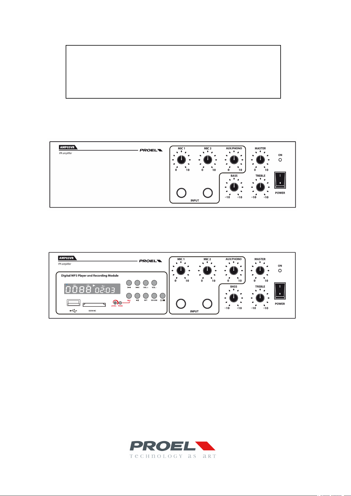
Amplificatore PA – PA Amplifier
AMP03V / AMP03VR
AMP03V
AMP03VR
Page 2

2
Page 3

INDICE
1. PRECAUZIONI D’USO ............................................................................................................................ 4
2. DESCRIZIONE .......................................................................................................................................... 6
3. FUNZIONI E CONTROLLI PANNELLO FRONTALE ........................................................................ 6
4. FUNZIONI E CONTROLLI PANNELLO POSTERIORE .................................................................... 7
5. MODULO LETTORE REGISTRATORE ............................................................................................... 8
6. INSTALLAZIONE ................................................................................................................................... 10
7. ESEMPI DI POSSIBILI CONNESSIONI ............................................................................................. 12
8. CARATTERISTICHE TECNICHE ........................................................................................................ 13
9. CONTENUTO DELLA CONFEZIONE ................................................................................................ 13
3
Page 4
1. PRECAUZIONI D’USO
AVVERTENZA:Per ridurre il rischio di folgorazione, non rimuovere il coperchio (o il pannello posteriore). All’interno non sono contenute parti
ATTENZIONE: Per ridurre il rischio d’incendio o di folgorazione, non esporre questo apparecchio alla pioggia o all’umidità.
Questo simbolo, ove compare, segnala la presenza di un voltaggio pericoloso non isolato all’interno del corpo dell’apparecchio –
Questo simbolo, ove appare, segnala, importanti istruzioni d’uso e manutenzione nel testo allegato. Leggere il manuale
RACCOMANDAZIONI:
Tutte le istruzioni di sicurezza e funzionamento devono essere lette prima di mettere in funzione l’apparecchio.
Conservare le istruzioni:
Le istruzioni di sicurezza e di funzionamento devono essere conservate per un futuro riferimento.
Il presente manuale è parte integrante del prodotto e lo deve accompagnare in caso di eventuali cambi di proprietà. In questo modo il nuovo
proprietario potrà conoscere le istruzioni relative a installazione, funzionamento e sicurezza.
Prestare attenzione:
Tutte le avvertenze sull’apparecchio e nelle istruzioni di funzionamento devono essere seguite fedelmente.
Osservare tutti gli avvertimenti.
Seguire le istruzioni:
Tutte le istruzioni per il funzionamento e per l’utente devono essere seguite.
Le note precedute dal simbolo
ISTRUZIONI DI SICUREZZA IN DETTAGLIO.
Acqua ed umidità:
L’apparecchio non deve essere utilizzato in prossimità di acqua (per es. vicino a vasche da bagno, lavelli da cucina, in prossimità di piscine
ecc.).
Ventilazione:
L’apparecchio deve essere posto in modo tale che la sua collocazione o posizione non interferisca con l’adeguata ventilazione. Per esempio,
l’apparecchio non deve essere collocato su un letto, copri-divano, o superfici simili che possono bloccare le aperture di ventilazione, o posto in
una installazione ad incasso, come una libreria o un armadietto che possono impedire il flusso d’aria attraverso le aperture di ventilazione.
Calore:
L’apparecchio deve essere posto lontano da fonti di calore come radiatori, termostati, asciuga biancheria, o altri apparecchi che producono
calore.
Alimentazione:
• L’apparecchio deve essere collegato soltanto al tipo di alimentazione descritto nelle istruzioni d’uso o segnalato sull’apparecchio.
• Se la spina in dotazione non combacia con la presa, rivolgersi ad un elettricista per farsi installare una presa appropriata.
Messa a terra o polarizzazione:
• Si devono prendere precauzioni in modo tale che la messa a terra e la polarizzazione dell’ apparecchio non siano pregiudicate.
• Le parti metalliche dell’apparecchiatura sono collegate a massa tramite il cavo d’alimentazione.
• Se la presa utilizzata per alimentazione non possiede collegamento a massa, rivolgersi ad un elettricista qualificato per fare collegare
l’apparato a massa tramite il terminale.
Protezione del cavo di alimentazione:
Il cavo di alimentazione elettrica deve essere installato in modo che non venga calpestato o pizzicato da oggetti posti sopra o contro, prestando
particolare attenzione a cavi e spine, prese a muro.
Pulizia:
• Quando l’unità deve essere pulita, è possibile eliminare la polvere utilizzando un getto d’aria compressa o un panno inumidito.
• Non pulire l’unità utilizzando solventi quali trielina, diluenti per vernici, fluidi, alcol, fluidi ad alta volatilità o altri liquidi infiammabili.
Periodi di non utilizzo:
Il cavo di alimentazione dell’apparecchio deve essere staccato dalla presa se rimane inutilizzato per un lungo periodo.
Ingresso di liquidi o oggetti:
riparabili dall’utente; affidare la riparazione a personale qualificato.
voltaggio sufficiente a costituire un rischio di folgorazione.
.
contengono importanti informazioni sulla sicurezza: leggerle con particolare attenzione.
4
Page 5

Si deve prestare attenzione che non cadano oggetti e non si versino liquidi nel corpo dell’apparecchio attraverso le griglie.
Uso sicuro della linea d’alimentazione:
• Quando si scollega l’apparato alla rete tenere saldamente sia la spina che la presa.
• Quando l’unità non viene utilizzata per un periodo prolungato, interrompere l’alimentazione estraendo la spina dalla presa
dell’alimentazione
• Per evitare danni alla linea d’alimentazione dell’apparato, non mettere in trazione il cavo d’alimentazione e non utilizzare un cavo
attorcigliato.
• Per evitare il danneggiamento del cavo d’alimentazione dell’apparato, assicurarsi che questo non venga calpestato o schiacciato da oggetti
pesanti.
Spostamento dell’unità:
Prima di ogni spostamento, verificare che l’unità sia spenta. Il cavo d’alimentazione deve essere estratto dalla presa, così come i collegamenti
dell’unità con altre linee.
Non smontare l’unità:
Non tentare di smontare né riparare da soli l’unità. Per qualsiasi problema non risolvibile con l’aiuto del presente manuale, rivolgersi a un
tecnico qualificato o consultare la nostra compagnia. Qualsiasi uso non appropriato può causare incendi o scosse elettriche.
Malfunzionamenti:
• Non tentare mai di eseguire riparazioni diverse da quelle descritte nel presente manuale.
• Contattare un centro di servizio autorizzato o del personale altamente qualificato nei seguenti casi:
- Quando l’apparato non funziona o funziona in modo anomalo.
- Se il cavo d’alimentazione o la spina sono danneggiati.
- Sono penetrati oggetti estranei o è stato versato del liquido nell’apparecchio.
- L’apparecchio è stato esposto alla pioggia.
- L’apparecchio non sembra funzionare normalmente o presenta un evidente
cambiamento nelle prestazioni.
- L’apparecchio è caduto, o il corpo è danneggiato.
Manutenzione:
L’utente non deve tentare di riparare l’apparecchio al di là di quanto descritto nelle istruzioni di funzionamento. Ogni altra riparazione deve essere
affidata a personale specializzato.
IMPORTANTI NORME DI SICUREZZA:
• Installare seguendo le istruzioni.
• Il voltaggio d’alimentazione dell’unità è abbastanza elevato per evitare il rischio di scosse elettriche, non installare, collegare o sconnettere
l’alimentazione quando l’apparato è acceso.
• Non aprire mai l’apparecchiatura: all’interno non esistono parti utilizzabili dall’utente.
• Se si avverte uno strano odore proveniente dall’apparato, spegnerlo immediatamente e sconnettere il cavo dell’alimentazione.
• Non ostruire le griglie di ventilazione dell’apparato.
• Evitare che l’unità lavori in sovraccarico per tempo prolungato.
• Non forzare i comandi (pulsanti, controlli, ecc.)
• Avvitare completamente i terminali a vite degli altoparlanti per garantire la sicurezza dei contatti.
Per ragioni di sicurezza, non annullare il collegamento a massa della spina. Il collegamento a massa è necessario per salvaguardare la
•
sicurezza dell’operatore
• Utilizzare unicamente i connettori e gi accessori specificati dal produttore.
• L’apparato deve essere collocato in un rack metallico (vedi INSTALLAZIONE) e tenuto lontano da:
• In presenza di temporali con fulmini o quando l’apparato non è utilizzato, estrarre la spina d’alimentazione dalla presa.
•
• PROEL S.P.A. declina ogni responsabilità in caso di scorretta installazione dell’unità.
Luoghi umidi
Esposizione diretta a fonti di calore (come luce solare).
Luoghi non sufficientemente ventilati
Per prevenire il rischio di incendi e scosse elettriche, è necessario tenere l’apparato lontano da spruzzi e gocce. Sopra l’apparato non
devono essere collocati vasi o altri oggetti contenenti liquidi. In caso si verifichino interferenze nel circuito di provenienza, il valore di THD
sarà superiore al 10%. Non installare questo apparato in una libreria o in altri luoghi a spazio ristretto
5
Page 6
Grazie per aver scelto un prodotto Proel e della fiducia riposta nel nostro marchio, sinonimo di professionalità,
accuratezza, elevata qualità ed affidabilità. Tutti i nostri prodotti sono conformi alle normative CE per utilizzazione
continua in impianti di diffusione sonora.
2. DESCRIZIONE
L’AMP03V è stato specificatamente progettato per la trasmissione di annunci microfonici e/o programmi
musicali in tutti i sistemi P.A.
Avendo, oltre alla normale alimentazione di rete, anche l’alimentazione a 12Vdc si presta particolarmente alle
esigenze di diffusione sonora Veicolare.
Esso presenta:
• Due ingressi MIC
• Un ingresso PHONO/AUX con sensibilità commutabile mediante selettore
• Indicatore di accensione a led
• Controllo generale del volume
• Controllo del volume microfono MIC1
• Controllo del volume microfono MIC2
• Controllo del volume AUX
• Regolazione toni bassi e alti
• Vite per connessione a terra
• Quattro uscite di cui tre a tensione costante (100V/70V/25V) e una a impedenza costante (4Ω)
• Funzione Priorità dell’ingresso MIC1
• Modulo registratore/riproduttore file Formato MP3 (solo AMP03VR)
• Kit veicolare opzionale comprensivo di staffa di fissaggio amplificatore e cavo di alimentazione
completo di fusibile
• Alimentazione: 220Vac / 117 Vac 50-60 Hz ; 12 Vdc
Prodotto conforme alla normativa CE
3. FUNZIONI E CONTROLLI PANNELLO FRONTALE
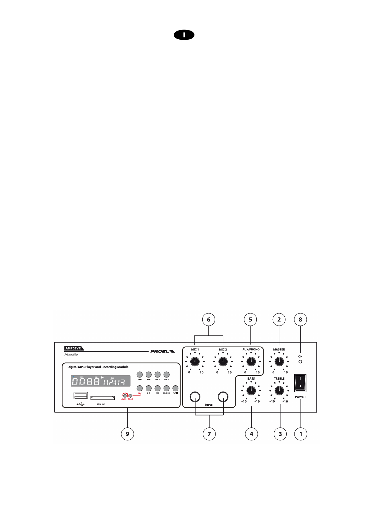
fig.1
1. POWER
Interruttore principale
2. MASTER
Controllo volume generale
6
Page 7
3. TREBLE
Controllo toni Alti
4. BASS
Controllo toni Bassi
5. AUX/PHONO
Controllo volume ingresso PHONO/AUX posteriore
6. MIC1 – MIC2
Controllo di volume ingressi MIC1 e MIC2
Nota: MIC1 ha la funzione di priorità sugli altri ingressi
7. INGRESSI MIC1 - MIC 2
Jack mono 6.3 mm
8. LED di Accensione
9. Modulo Lettore / Registratore in formato MP3 (solo AMP03VR)
4. FUNZIONI E CONTROLLI PANNELLO POSTERIORE
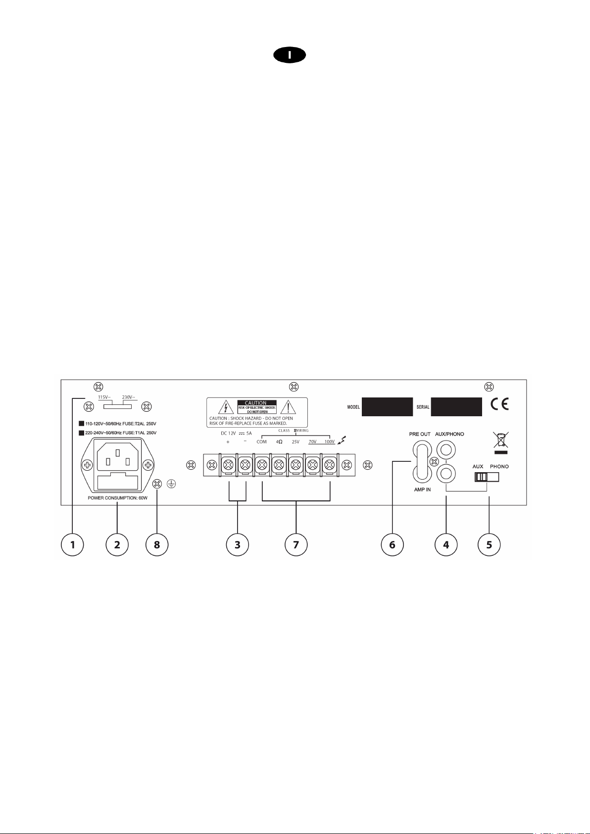
1. SELETTORE TENSIONE DI RETE
2. INGRESSO ALIMENTAZIONE DI RETE
Collegare l’unità alla rete 230Vac 50/60Hz o 117Vac 50/60Hz
Nota: per l’utilizzo alla tensione di riferimento è 117Vac 50/60Hz spostare il selettore di rete nella posizione
117Vdc
Alloggio per fusibile T 1A 250V.
3. MORSETTI ALIMENTAZIONE DC 12V
I due morsetti permettono all’unità di essere alimentata in corrente continua attraverso una sorgente esterna
es. generatore o batteria a 12V DC.
Nel caso di utilizzo in corrente continua inserire nella linea d’alimentazione V DC un fusibile da 5A 12V.
4. AUX/PHONO IN
Ingresso ausiliario (RCA)
Collegare a quest’ingresso una sorgente sonora esterna (lettore CD, MP3, DVD ecc.)
fig.2
7
Page 8
5. SELETTORE
6. INSERT
Consente di selezionare la sensibilità tra AUX e PHONO
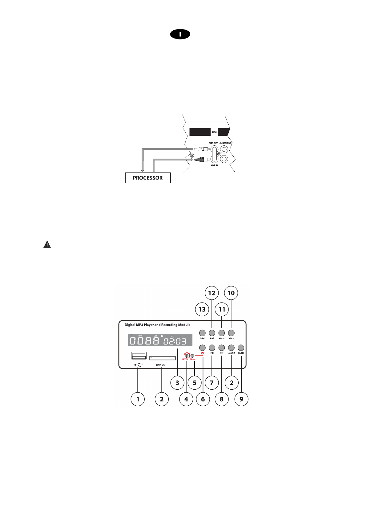
Di serie l’ingresso AMP IN è collegato con l’uscita PRE OUT con un ponticello. E’ possibile ottenere
un’ottimizzazione del segnale da amplificare interponendo tra i due terminali un’unità esterna (es.
equalizzatore, processore ecc.). Per il collegamento riferirsi alla figura.
7. MORSETTI DI USCITA
Collegare i diffusori tra COM e la tensione desiderata (100V/ 70V/100V). Vedi paragrafo 6.2
8. Vite GND
Permette la messa a terra delle parti meccaniche dell’unità qualora ì la presa di corrente non sia provvista del
“polo di terra”
Attenzione
La connessione deve essere effettuata da personale qualificato.
5. MODULO LETTORE REGISTRATORE
(fig.2 rif. 8).
1. Interfaccia USB
2. Interfaccia SD/MMC
3. DISPLAY
4. LEVEL
Regola il livello della registrazione
fig.3
8
Page 9

5. PEAK
Il led s’illumina quando viene raggiunto il livello di picco.
Per una buona qualità della registrazione evitare che il led di picco rimanga costantemente acceso
6. REC
Dopo aver acceso il modulo (fig.3 rif .9) e regolato opportunamente il livello di registrazione (fig.3 rif .4),
questo inciderà sulla buona riuscita della registrazione, collegare una sorgente audio a uno dei 3 ingressi
disponibili (fig.1 rif .7 - fig.2 rif 4) e regolarne il rispettivo livello.
Inserire la chiavetta USB o la scheda SD negli appositi ingressi rispettivamente (fig.3 rif .1 - fig.3 rif .2 ).
Premendo il tasto REC nel display comparirà la scritta REC e il dispositivo sarà pronto per la registrazione,
premendo nuovamente il tasto REC la scritta REC inizia a lampeggiare e dopo qualche istante la
registrazione avrà inizio e a display verrà visualizzato il contatore con il tempo di registrazione corrente .
Per terminare la registrazione premere il tasto (fig.1 rif .9) e assicurarsi che il contatore non venga più
visualizzato.
Nota:
se il supporto di memoria contiene dei brani questi andranno automaticamente in riproduzione con la
funzione repeat all attivata. Questo non impedisce di iniziare una registrazione.
Nel supporto di memoria verrà creata una cartella F:\RECORD\LINEIN all’interno della quale verrà
memorizzata la registrazione con il seguente nome FILE_001.MP3, se si ripete il processo il nuovo file
verrà memorizzato come FILE_002.MP3 e così via.
Dal modulo registratore riproduttore non è possibile sovrascrivere o eliminare una registrazione
esistente
7. PLAY / PAUSA
Dopo aver acceso il modulo (fig.3 rif .9) inserire la chiavetta USB o la scheda SD negli appositi ingressi
rispettivamente (fig.3 rif .1 - fig.3 rif .2 )
Se il supporto di memoria contiene dei brani questi andranno automaticamente in riproduzione con la
funzione repeat all attivata.
Nota:
Saranno riprodotti tutti i brani presenti nel supporto di memoria anche se sono state create delle
sottocartelle da PC
La riproduzione di un brano registrato dal modulo sarà contrassegnata dalla scritta a display “FrE”
Durante la riproduzione, premendo il tasto PLAY/PAUSA (fig.3 rif .7) la riproduzione si blocca e rimarrà tale
fino ad una nuova pressione del tasto.
8. RPT
Premendo ciclicamente questo tasto possiamo impostare il tipo di riproduzione:
“ nessun simbolo ” i brani vengono riprodotti una sola volta
“ REP I ” ripete ciclicamente lo stesso brano
“ REP ALL ” ripete ciclicamente tutta la sequenza di brani
“ REP ” ripete in maniera casuale i brani una sola volta
9. ON OFF /STOP
Premendo il pulsante per 3 secondi il modulo si accende (Funzione ON). Premendo nuovamente il pulsante
per 3 secondi il modulo si spegne (funzione OFF)
Premendo questo tasto durante la riproduzione di un brano, essa viene arrestata (funzione STOP).
10. VOL +
Premere il pulsante per aumentare il livello di volume di riproduzione
11. VOL –
Premere il pulsante per diminuire il livello di volume di riproduzione
12. BRANO SUCCESSIVO
Premere il pulsante per passare al brano successivo
13. BRANO PRECEDENTE
Premere il pulsante per passare al brano precedente
9
Page 10
6. INSTALLAZIONE
1. Connessioni d’ingresso
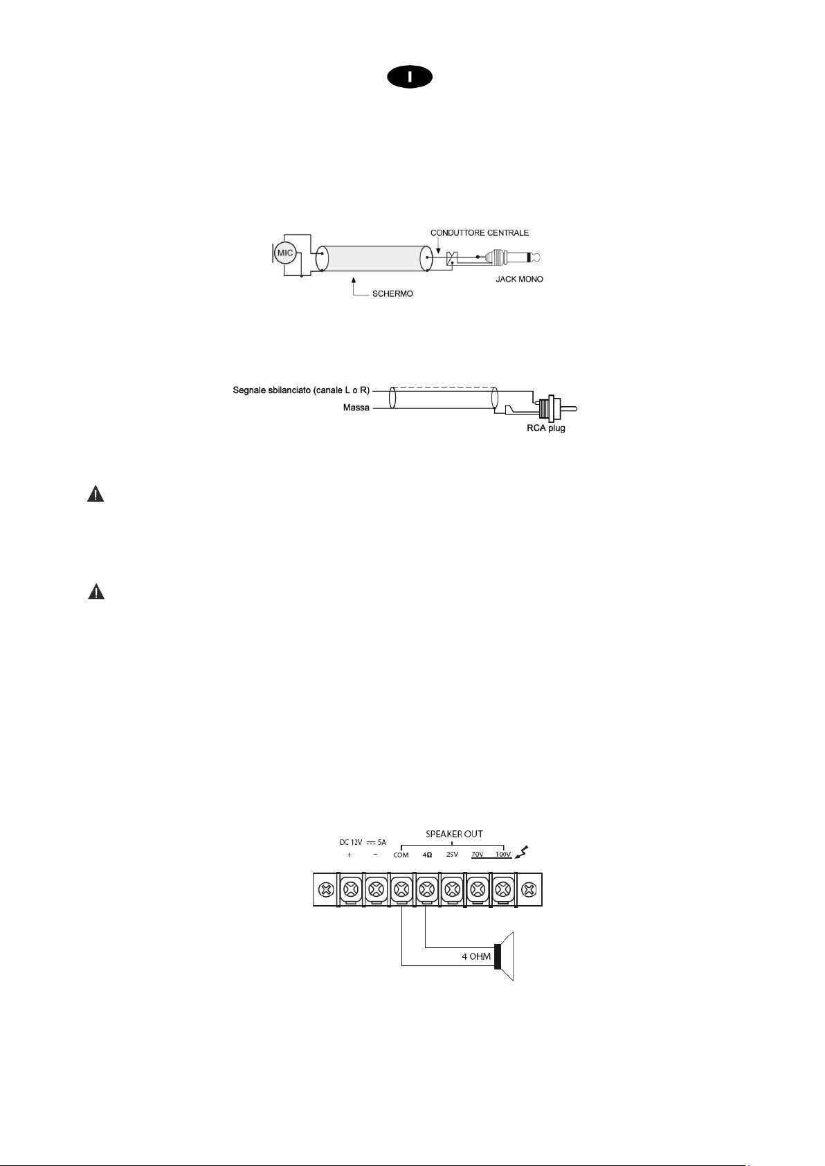
• Gli ingressi MIC1 e MIC2 (fig1, rif.7) sono di tipo Jack Mono 6.3 e sono utilizzabili per il collegamento di
microfoni dinamici a bassa impedenza (30-600Ω). L’ingresso MIC1 è provvisto della funzione VOX e, quando
viene pilotato con un segnale, provvede a renderlo prioritario escludendo tutti gli altri ingressi; in questo modo
viene diffuso unicamente il segnale audio dell’ingresso MIC1.
• L’ingresso AUX/PHONO (fig.2, rif.4) è utilizzato per il collegamento di sorgenti audio con uscita del segnale
livello “linea” (es. sintonizzatore AM/FM, lettore di cassette, lettore CD, ecc.). Le prese R e L consentono
l’ingresso del canale destro (R) e sinistro (L) attraverso connettori RCA
• Presa cavo d’alimentazione.
.
Consente l’alimentazione dell’unità (fig.2 rif.2)
Attenzione
Prima di alimentare l’unità, controllare che il selettore della tensione di alimentazione (fig.2 rif.1) sia
posizionato sullo stesso valore della tensione di rete.
2. Connessioni d’uscita
Attenzione
Per prevenire il rischio di contatto con scariche elettriche non toccare mai le uscite dell’amplificatore quando
esso è in funzione.
• Connessione altoparlanti.
Per accedere ai morsetti di connessione altoparlanti (fig.2 rif. 7) rimuovere il coperchio di protezione
svitando le rispettive viti.
Il dispositivo può essere usato sia con altoparlanti a impedenza costante (4Ω) che a tensione costante
(25,70,100V). Effettuare le connessioni tenendo conto delle seguenti indicazioni.
Linea ad impedenza costante
Per ottenere una linea a impedenza costante (4Ω) collegare i due terminali rispettivamente al morsetto COM
e 4Ω.
− Al fine di garantire il massimo rendimento, l’impedenza totale degli altoparlanti collegati alla linea, deve
essere uguale all’impedenza dell’uscita dell’amplificatore.
− La somma della potenza dei diffusori non deve essere inferiore alla potenza di uscita dell’amplificatore.
− Si consiglia di ridurre al minimo la lunghezza delle connessioni, in ogni caso, aumentare la sezione del
cavo in funzione della distanza coperta.
10
Page 11
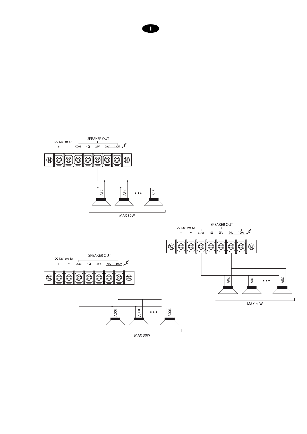
Linea a tensione costante
Per ottenere una linea a tensione costante (25,70,100V) collegare i due terminali rispettivamente al
morsetto COM e a quello contrassegnato con il valore di tensione desiderato.
− Gli altoparlanti devono essere dotati di un trasformatore avente una tensione d’ingresso uguale a quella
fornita dall’amplificatore.
− La somma della potenza degli altoparlanti non deve superare la massima potenza di uscita
dell’amplificatore.
Collegamento a 25V Collegamento a 70V
Collegamento a 100V
11
Page 12
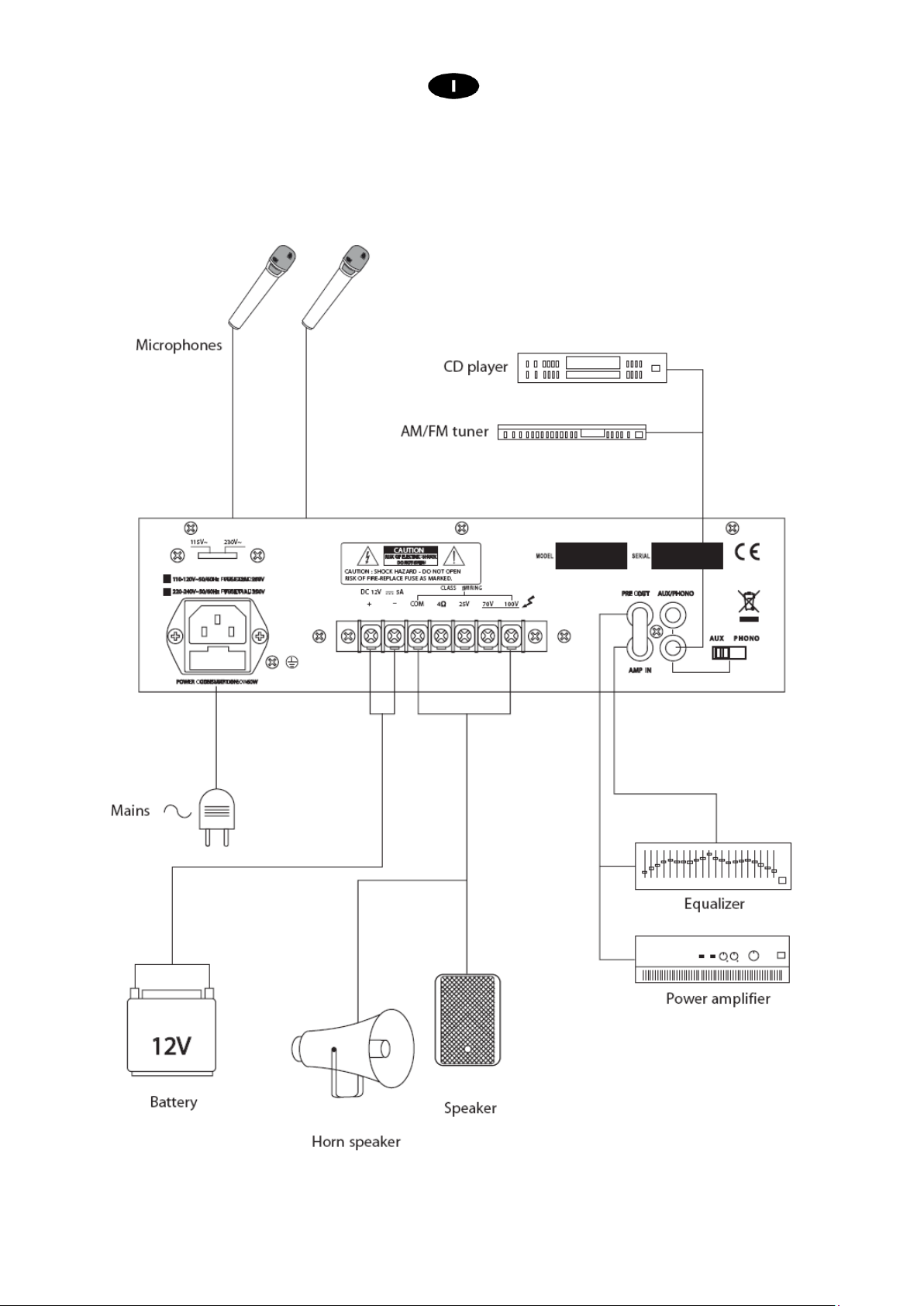
7. ESEMPI DI POSSIBILI CONNESSIONI
12
Page 13
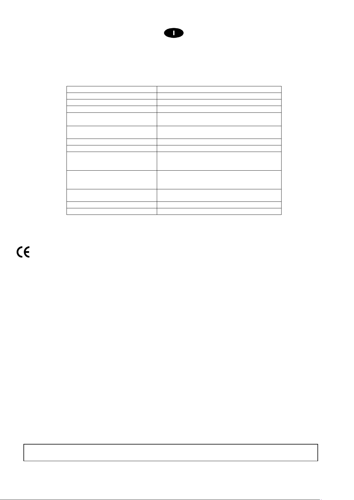
AMP03
V / AMP03VR
8. CARATTERISTICHE TECNICHE
Modello
Potenza d’uscita RMS AC 30W – DC 25W
Uscita a tensione costante 100V / 70V / 25V
Uscita a impedenza costante
Connettori d’Ingresso
Connettori d’uscita
Risposta in frequenza 80Hz – 18KHz
THD < 1%
Rapporto segnale rumore MIC1, MIC2:≥65dB
Sensibilità Ingressi
Tensione di alimentazione 220V ac – 117V ac 50/60Hz
Dimensioni (LxHxP) (in mm.) 280x190x75
Peso (Kg) 4,5
4Ω
MIC1, MIC2: Jack 6.3mm (30 - 600Ω) sbilanc.
AUX /PHONE: RCA 10 KΩ
4Ω, su morsettiera
25/70/100V su morsettiera
AUX : ≥75dB
PHONE: ≥55dB
MIC1, MIC2: -50dBV @ 1KHz
AUX : -20dBV @ 1KHz
PHONE: -50dBV @ 1KHz
12Vdc 5A
Il prodotto è conforme alla Direttiva 89/336/CEE (Compatibilità Elettromagnetica)
e successive modifiche 92/31/CEE e 93/68/CEE, secondo i seguenti standard:
EN 50082-1:1997, EN 55013:1990, EN 55020:1994
inoltre, è conforme alla Direttiva 73/23/CEE (Bassa Tensione)
e successive modifiche 93/68/CEE, secondo il seguente standard:
EN 60065:1998
9. CONTENUTO DELLA CONFEZIONE
Amplificatore
Cavo di alimentazione di rete
Manuale di utilizzo
La Proel SpA persegue una politica di costante ricerca e sviluppo, di conseguenza si riserva il diritto di apportare miglioramenti ai
prodotti esistenti, senza preavviso e in qualunque momento. REV. 00 41/11
13
Page 14

INDICE
2. DESCRIPTION ......................................................................................................................................... 17
3. FRONT PANEL FUNCTIONS AND CONTROLS .............................................................................. 17
4. REAR PANEL FUNCTIONS AND CONTROLS ................................................................................ 18
5. PLAYING AND RECORDING MODULE............................................................................................. 19
6. INSTALLATION ....................................................................................................................................... 21
7. CONNECTION EXAMPLE ..................................................................................................................... 23
8. TECHNICAL FEATURE ......................................................................................................................... 24
9. PACKAGE CONTENT ............................................................................................................................ 24
14
Page 15
1. IMPORTANT SAFETY INSTRUCTIONS
CAUTION: To reduce the risk of electric shock do not remove cover (or back panel). No user serviceable parts inside. Refer servicing to
WARNING: To reduce the risk of fire or electric shock, do not expose this apparatus to rain or moisture.
This symbol is intended to alert the user of the presence of uninsulated dangerous voltage within the product enclosure that may
This symbol is intended to alert the user of the presence of important operating and maintenance (servicing) instruction in the
INSTRUCTIONS:
All safety and operating instructions should be read before the product is operated.
Retain these instructions:
All safety and operating instructions should be retained for future reference.
This owner’s manual should be considered as a part of the product, it must accompany it at all times, and it needs to be delivered to the new user
when this product is sold. In this way the new owner will be aware of all the installation, operating and safety instructions.
Heed all warnings:
All warnings on the product and in owner’s manual should be adhered to.
Heed all warnings.
Follow all instructions:
All operating and user’s instructions must be followed.
Sentences preceded by symbol contain important safety instruction. Please read it carefully.
DETAILED SAFETY INSTRUCTIONS.
Water and moisture:
This apparatus should not be used near water (i.e. bathtub, kitchen sink, swimming pools, etc.)
Ventilation:
This apparatus should be placed in a position that doesn’t interfere with its correct ventilation. This unit, for example, should not be placed on a
bed, sofa cover o similar surfaces that could cover ventilation openings, or placed in a built-in installation, such a bookcase or a cabinet that
could block air flow trough ventilation openings.
Heat:
This apparatus should be placed away from sources of heat, like radiators, heat registers, stoves or other products (including amplifiers) that
produce heat.
Power sources:
•
This apparatus should only be connected to a power source of type specified in this owner’s manual or on the unit.
•
If the supplied AC power cable plug is different from wall socket, please contact an electrician to change the AC power plug.
Grounding or Polarization:
•
All precautions must be observed in order to avoid defeating grounding or polarization.
•
Unit metal parts are grounded through the AC power cord.
•
If the AC power outlet doesn’t have grounding, consult an electrician for outlet grounding.
Power cable protection:
The power cable should be routed in such a way that it will not be walked on or pinched by items placed upon or against it, paying particular
attention to cables at their connections, receptacles and wall outlet.
Cleaning:
•
You can clean the exterior of the unit with compressed air or a damp cloth.
•
Don’t clean the unit using solvents like trichloroethylene, thinners, alcohol, or other volatile or flammable fluids.
Non use periods:
The unit AC power cable should be unplugged from the outlet if it’s unused for long periods.
qualified personnel only.
be of sufficient magnitude to constitute a risk of electric shock to persons.
literature accompanying the appliance. Please carefully read the owner’s manual.
15
Page 16

Objects or liquid entry into the unit:
Be careful that no objects fall into the unit or that no liquid is spilled inside the unit through ventilation openings.
Safe power line use:
•
Hold the plug and the wall outlet firmly while disconnecting the unit from AC power.
•
When the unit will not be used for a long period of time, please unplug the power cord from AC power outlet.
•
To avoid power cable damage, don’t strain the AC power cable and don’t bundle it.
•
In order to avoid damage to the unit's power cable, be sure that the power cable is not walked on or pinched by heavy objects.
Unit relocation:
Before relocating the unit, please control the unit is turned off. The power cord must be unplugged from the wall outlet, and all the connecting
cables should be disconnected as well.
Do not open this unit:
Do not attempt to open or repair this unit yourself. For any problem not described in this owner’s manual, please refer to qualified personnel only
or consult us or your National Distributor. Any improper operation could result in fire or electric shock.
Damages requiring services:
•
Do not attempt to perform operations not described in this user’s manual.
•
In the following cases please refer to an authorized service center or skilled personnel:
- When the unit works improperly or it doesn’t work at all.
- If power cord or plug is damaged.
- If liquid has spilled, or objects have fallen into the unit.
- The unit has been exposed to rain.
- The unit doesn’t operate normally or exhibits a marked change in performance.
- If the product has been dropped or has been damaged in any way.
Maintenance:
The user shouldn’t attempt maintenance not described in this user’s manual. All maintenance should be performed by qualified personnel only.
IMPORTANT SAFETY INSTRUCTIONS:
•
Install this unit following owner’s manual instructions.
•
Do not install, connect or disconnect power supply when the unit is powered, otherwise there is a high risk of electric shock.
•
Do not open the unit, there are no user serviceable parts inside.
•
If you detect a particular smell from the unit, please immediately turn it off and disconnect the AC power cord.
•
Don’t block the unit's ventilation openings.
•
Avoid using this unit in overload for a long period.
•
Don’t force commands (switches, controls, etc.)
•
To obtain good speaker wire contact, please tighten the screw terminals firmly.
•
For safety reasons, do not defeat the grounding connection. Grounding is for user safety.
•
Use only connectors and accessories suggested by the manufacturer. .
•
This unit should be fitted in an equipment rack (see INSTALLATION) and kept far from:
Wet places
Direct exposure to heat sources (like sun light)
Improperly ventilated places
•
Disconnect the power cord during storms or when the unit is not in use.
•
In order to prevent fire and reduce risk of electric shock, it is necessary to keep the unit far from dripping water. Please don’t put cups,
vases or other object containing liquids over the unit. In case of interference from source signal, THD value will raise over 10%. Don’t place
this unit in a bookshelf or in other enclosed spaces.
•
PROEL S.P.A. is not responsible for any damage that occurs due to a incorrect installation of the unit.
16
Page 17
Thank you for choosing Proel and for your trust in our brand: we strive to guarantee professionalism, accuracy, high
quality and reliability to our customers. All of our products comply with EC regulations on sound reinforcement devices.
2. DESCRIPTION
AMP03V was specifically designed to deliver announcements and/or music programs through P.A. systems. It
can be powered both from a standard AC mains network or by 12 V DC, therefore it is particularly useful for
audio distribution on board vehicles.
It features:
• Two MIC inputs
• One PHONO/AUX input with selectable sensitivity
• LED power indicator
• Master Volume
• MIC1 Volume Control
• MIC2 Volume Control
• AUX Volume Control
• Low and High Tone Controls
• A screw for ground wiring
• Four outputs: three constant voltage outputs (100 V/70 V/25 V) and one constant impedance output (4 Ω)
• MIC1 Input Priority Function
• MP3 file recorder/player module (only AMP03VR)
• Optional Vehicle Mounting Kit with fixing bracket for the amplifier and power cable with fuse
• Power supply: 220 V AC / 117 V AC 50-60 Hz ; 12 V DC
This product complies with EC regulations
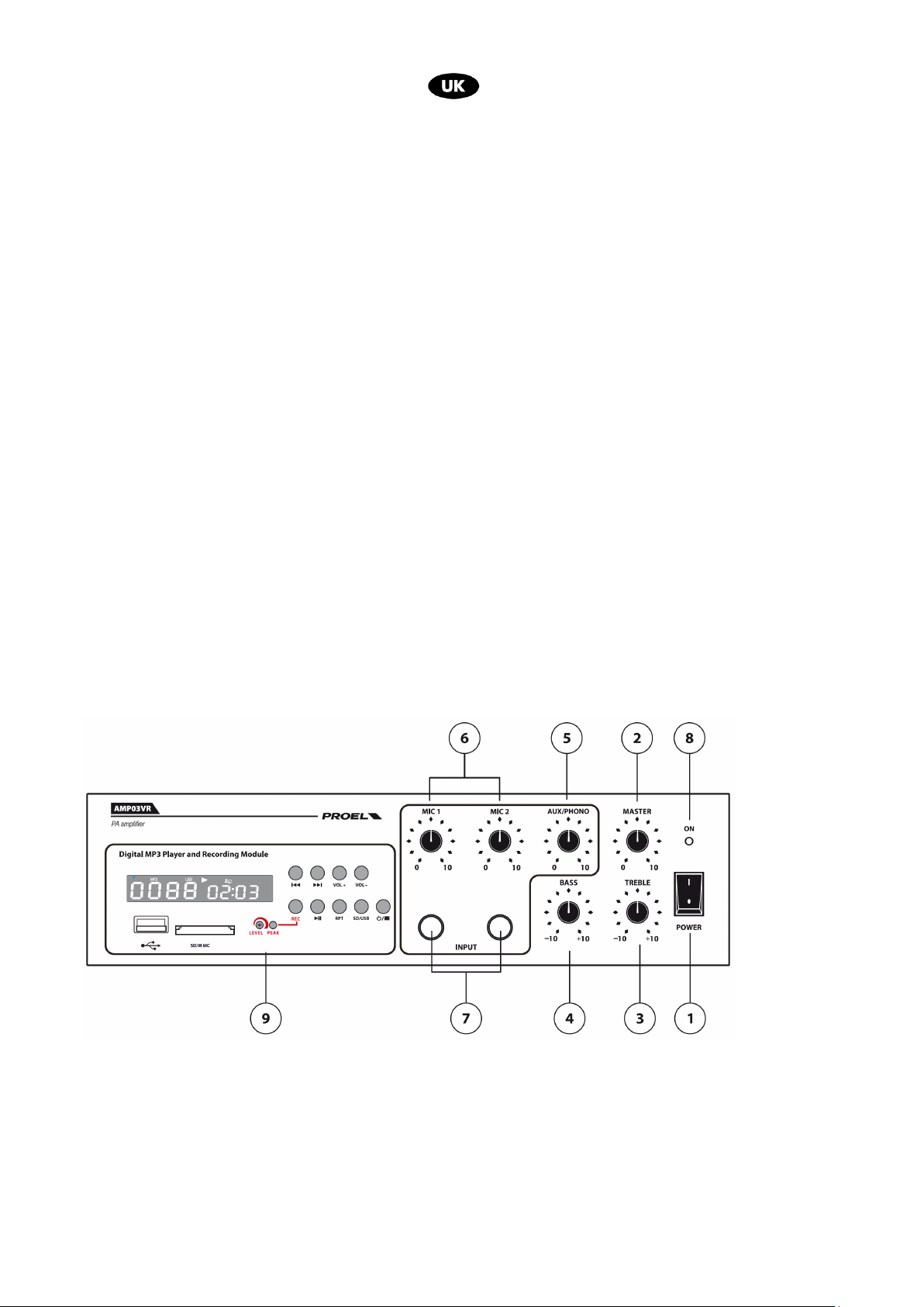
3. FRONT PANEL FUNCTIONS AND CONTROLS
fig.1
1. POWER
Power switch
2. MASTER
Master Volume
3. TREBLE
High Tone Control
17
Page 18
4. BASS
Low Tone Control
5. AUX/PHONO
PHONO/AUX rear input volume control
6. MIC1 – MIC2
Volume Controls of MIC1 & MIC2 inputs
Note: MIC1 has priority over all the other inputs
7. MIC1 - MIC 2 INPUT
6,3 mm mono jack
8. Power LED
9. MP3 Reader/Recorder Module (only AMP03VR)
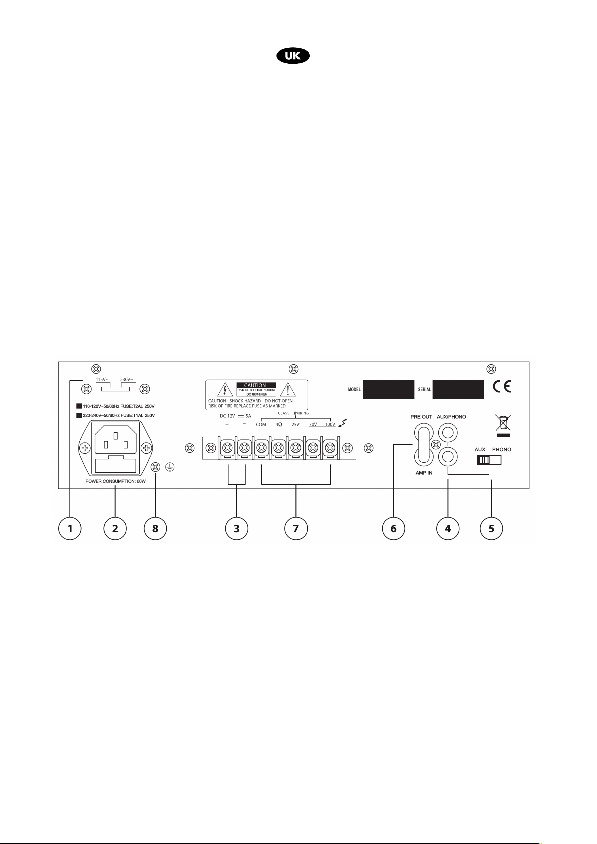
4. REAR PANEL FUNCTIONS AND CONTROLS
1. POWER SUPPLY SELECTOR
2. MAINS SOCKET
Connect the unit to a 230 V AC 50/60 Hz outlet or 117 V AC 50/60 Hz
Note: if you use a 117 V AC 50/60 Hz power supply, switch the selector to the 117 V DC position
T 1A 250V fuse housing.
3. 12 V DC POWER CONNECTORS
These two connectors allow the unit to be powered by direct current through an external power source such
as a generator or a 12 V DC battery.
If you opt for direct current powering, please insert a 5 A 12 V fuse in the V DC supply line.
4. AUX/PHONO IN
Auxiliary input (RCA)
Connect this input to an external audio source (CD player, MP3, DVD reader, etc.)
5. SELECTOR
Switches between AUX and PHONO
fig. 2
18
Page 19
6. INSERT
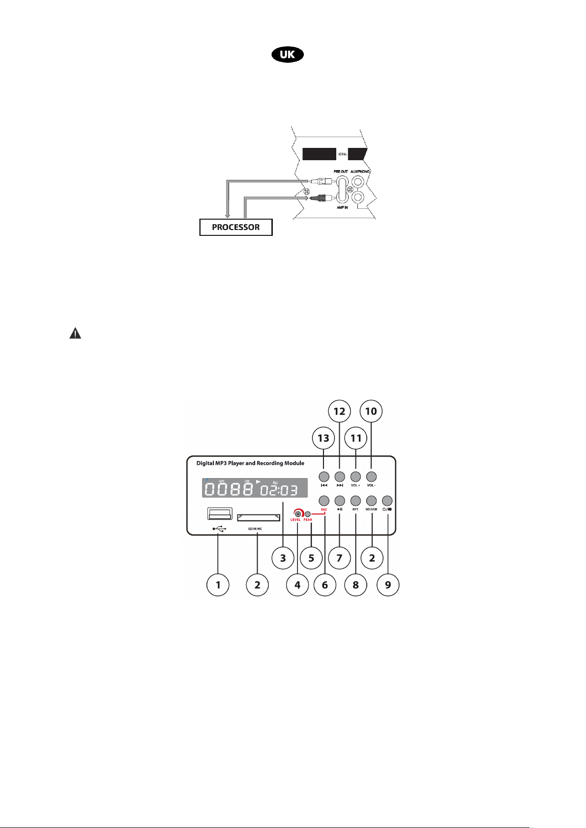
The AMP IN input is connected with the PRE OUT output by a jumper. The signal requiring amplification
can nonetheless be optimized by interposing an external unit (i.e. equalizer, processor, etc.) between the
two terminals. Refer to the illustration below for the connection.
7. OUTPUT TERMINALS
Connect the speaker lines to the COM terminal and to the desired constant voltage terminal (100 V / 70 V /
100 V). See paragraph 6.2
8. GND Screw
Allows grounding of the mechanical parts of the unit in case the mains cable has no ground pole. (fig.2 ref.8).
Warning
The connection must be carried out by qualified professionals.
5. PLAYING AND RECORDING MODULE
1. USB Interface
2. SD/MMC Interface
3. DISPLAY
4. LEVEL
Sets the recording level
5. PEAK
This LED lights up when the peak level is reached.
To ensure a good recording quality, the peak LED should not be constantly lit.
fig. 3
19
Page 20

6. REC
After having switched on the module (fig. 3, ref. 9) and set the recording level (fig. 3, ref. 4), connect an audio
source to one of the three available inputs (fig. 1, ref. 7 – fig. 2, ref. 4) and adjust its level.
Insert the USB key or the SD card in the respective inputs (fig. 3, ref. 1 – fig. 3, ref. 2).
Press the REC button: the display will now show “REC” and the device will be ready to record. Press REC
again and the REC indication on the display will start flashing and in a few seconds the recording will begin.
The display will also show a meter with the current recording time.
When you wish to stop recording, press the REC button again (fig. 1, ref. 9) and make sure the meter is no
longer visualized.
7. PLAY / PAUSE
Switch on the module (fig. 3, ref. 9) and insert the USB key or the SD card in one of the respective inputs (fig.
3, ref. 1 – fig. 3, ref. 2 ).
If the memory device contains any audio files, they will be automatically played when the Repeat All function
is activated.
When you are playing something and you press the PLAY/PAUSE button (fig. 3, ref. 7) the reproduction will
stop and will not resume unless you press the button once more.
8. RPT
Use this button to set the type of reproduction:
“ no icons ”: audio files are played only once
“ REP I ”: the first file is played repeatedly
“ REP ALL ”: the sequence of files is played repeatedly
“ REP ”: randomly plays the files in the sequence only once.
9. ON OFF /STOP
Press the button holding it down for three seconds to turn on the module (ON). If you hold it down for three
more seconds, the unit will turn off (OFF).
Press this button while an audio file is being played to stop the reproduction (STOP).
10. VOL +
Press this button to increase the volume.
11. VOL –
Press this button to decrease the volume.
12. NEXT TUNE
Press this button to skip to the next audio file.
13. LAST TUNE
Press this button to go back to the last audio file.
Note:
If the memory device contains any audio files, they will be automatically played when the Repeat All
function is activated, but it will not prevent you from starting a recording. The memory device will create
a F:\RECORD\LINEIN file in which the recording will be memorized as FILE_001.MP3. If the process is
repeated, the new file will be memorized as FILE_002.MP3 and so on.
You cannot overwrite or delete an existing recording from the playing and recording module.
Note:
All the audio files in the memory device will be played even if sub-files have been created from the PC.
When a file stored in the module is being played, the display will show “FrE”.
20
Page 21
6. INSTALLATION
1. Input connections
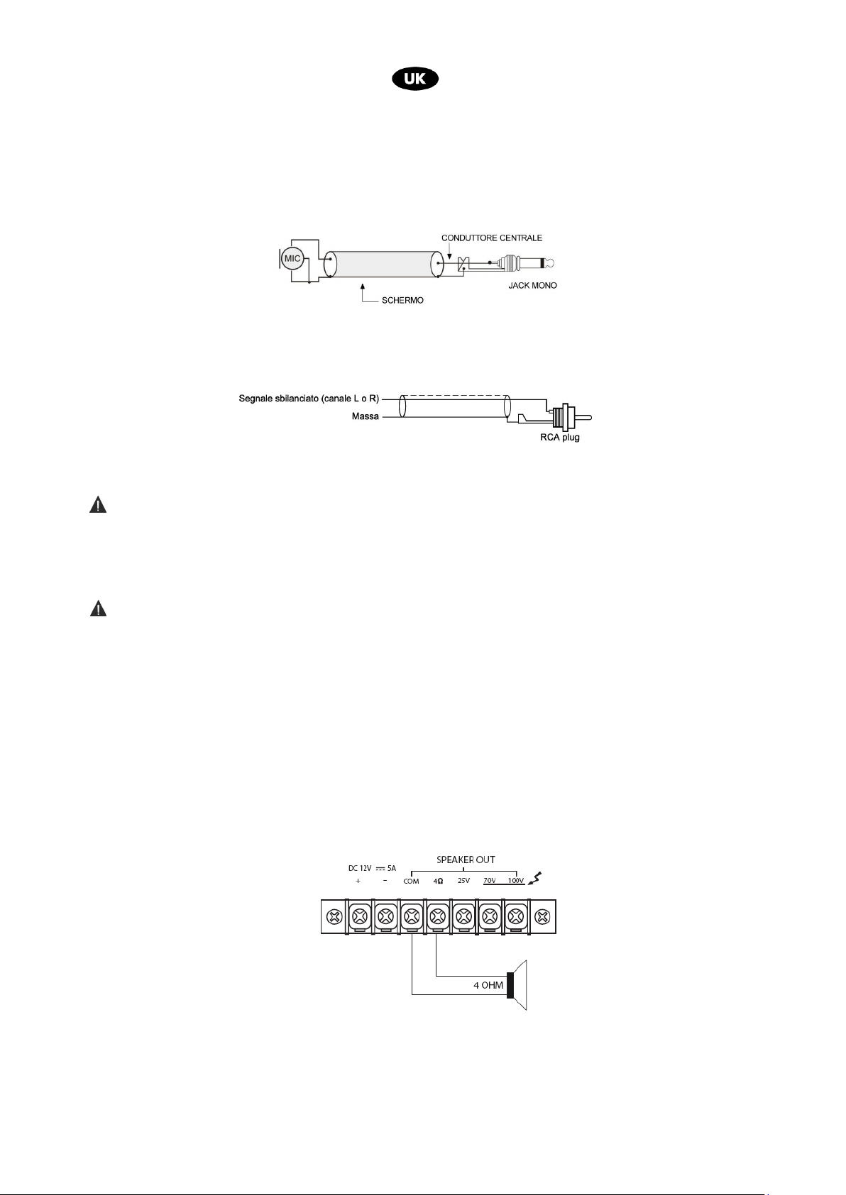
• MIC1 and MIC2 inputs (fig. 1, ref. 7) are 6.3 mm mono jacks and can be used to connect low impedance (30600 ) dynamic microphones. The MIC1 input features a VOX function that, when driven by a signal,
prioritizes it and excludes all other inputs: in this way only the audio signal present on the MIC1 input is
reproduced at the output.
• The AUX/PHONO input (fig. 2, ref. 4) is used to connect line level sound signal source (i.e. AM/FM tuner,
cassette player, CD player, etc.). The R and L RCA connectors allow the signal input of the right and left
channel respectively.
• Power Supply Cable
This supplies power to the unit (fig. 2, ref. 2).
Warning
Before you connect the unit to the mains outlet, make sure the power supply voltage selector (fig. 2, ref. 1)
matches the actual mains voltage.
2. Output connections
Beware!
To avoid the risk of electric shock do not touch the amplifier outputs when the amplifier is turned on.
• Speaker connection
To access the speaker connectors (fig. 2, ref. 7) unscrew each respective screw terminal to remove the
protective cover.
The unit can be used both with constant impedance speakers (4 Ω) and with constant voltage speakers (25 V,
70 V, 100 V). Make the connections according to the following indications.
Constant impedance line
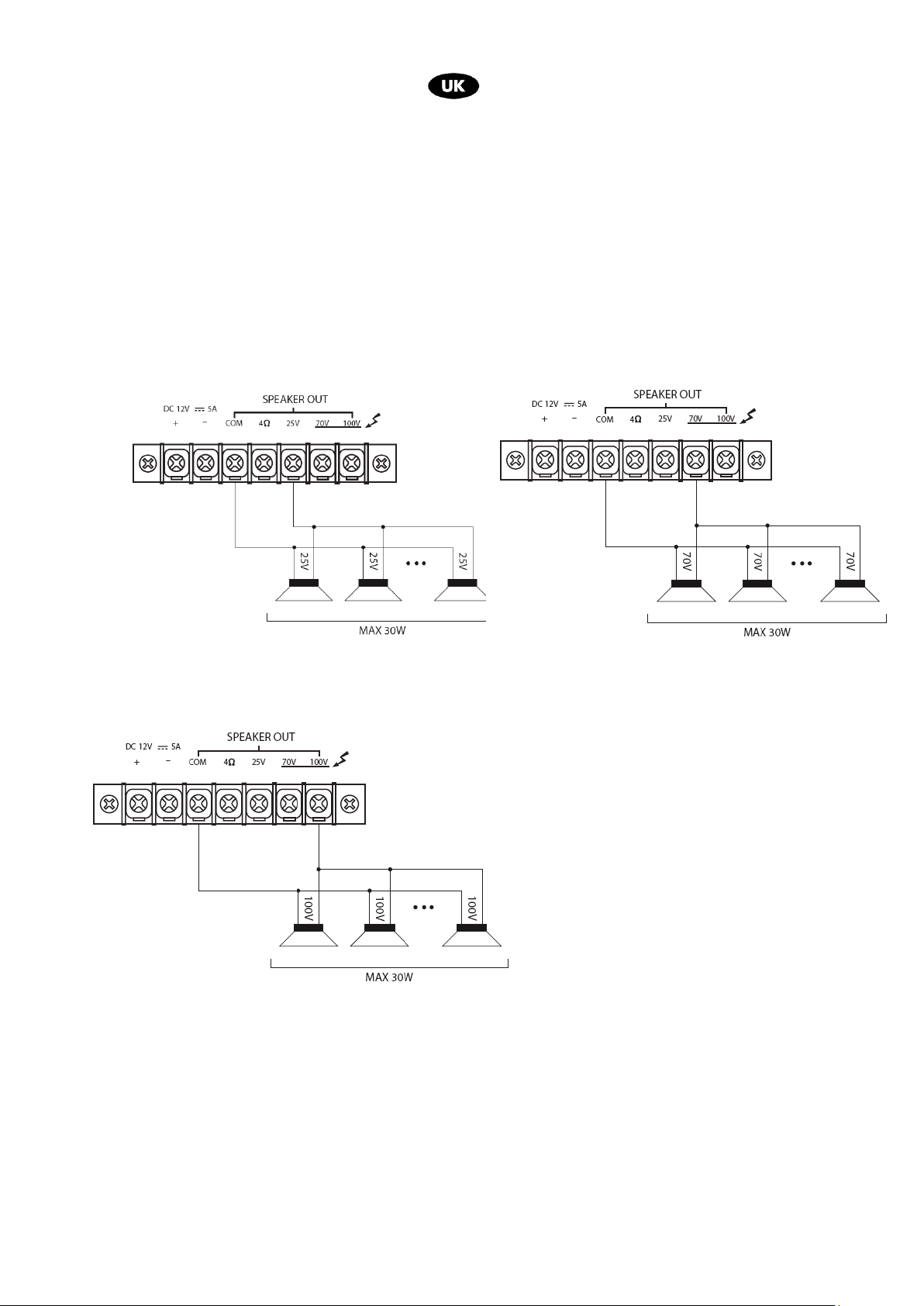
Connect one of the speaker line terminals to the COM terminal and the other to the 4 Ω terminal to get a
constant impedance line (4 Ω) .
−−−− In order to get the maximum results, the total impedance of the speakers connected to the line has to
equal the amplifier output load impedance,
−−−− The sum of the speakers power should not be lower than the amplifier output power.
−−−− We advise keeping the connection cables as short as possible. In any case, the longer the cable is, the
larger its diameter should be.
21
Page 22
Constant voltage line
In order to get a constant voltage line (25 V, 70 V, 100 V) connect one of the speaker/transformer lines to
the COM terminal and the other to the terminal bearing the voltage value that you need.
−−−− The speakers need a transformer with an input voltage equal to the input voltage provided by the
amplifier.
−−−− The sum of the speakers power should not be higher than the maximum amplifier output power.
25 V connection 70 V connection
100 V connection
22
Page 23
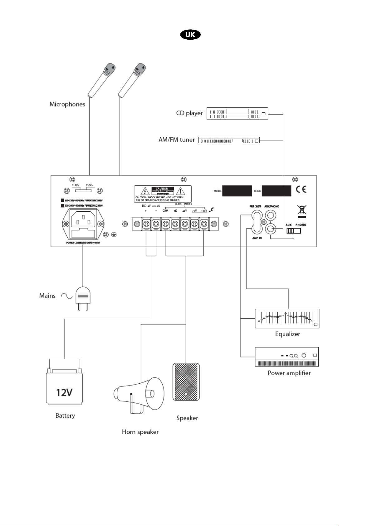
7. CONNECTION EXAMPLE
23
Page 24
Model
AMP03V / AMP03VR
8. TECHNICAL FEATURE
RMS Output Power AC 30 W – DC 25 W
Constant Voltage Output 100 V / 70 V / 25 V
Constant Impedance Output
Connettori d’Ingresso
Output connectors
Frequency Response 80 Hz – 18 kHz
THD < 1%
Signal-to-noise ratio MIC1, MIC2:≥65 dB
Input Sensitivity
Power Supply 220 V AC – 117 V AC 50/60 Hz
Dimensions (LxHxP) (in mm.) 280x190x75
Weight (kg) 4,5
4 Ω
MIC1, MIC2: unbalanced 6.3mm jack (30 – 600 Ω)
AUX /PHONE: RCA 10 kΩ
4 Ω, on screw terminal
25 V/70 V/100 V on screw terminal
AUX : ≥75 dB
PHONE: ≥55 dB
MIC1, MIC2: -50 dBV @ 1 kHz
AUX : -20 dBV @ 1 kHz
PHONE: -50 dBV @ 1 kHz
12 V DC 5 A
This product complies with Directive 89/336/CEE (Electromagnetic Compatibility)
and amendments 92/31/CEE and 93/68/CEE, according to the following standards:
EN 50082-1:1997, EN 55013:1990, EN 55020:1994
it is also compliant with Directive 73/23/CEE (Low Voltage)
and subsequnt amendments 93/68/CEE, according to the following standard:
EN 60065:1998
9. PACKAGE CONTENT
Amplifier
Power supply cable
User manual
Proel SpA is committed to a constant research and development policy and therefore reserves the right to change and improve its
products at any time without notice . REV. 00 41/11
24
Page 25

Page 26

PROEL S.p.A.
(World Headquarters - Factory)
Via alla Ruenia 37/43
64027 Sant’Omero (Te) – Italy
Tel: +39 0861 81241
Fax: +39 0861 887862
E-mail:
www.proelgroup.com
26
 Loading...