

Prodys ProntoNet User Manual

ProntoNet
User Manual
Ver 4.1.0
interstage
Phistersvej 31, 2900 Hellerup, Danmark
Telefon 3946 0000, fax 3946 0040
www.interstage.dk
- pro audio with a smile

Index
Index .................................................................................2
CE Declaration of Compliance ...................................................6
Introduction ........................................................................7
Installation Guide .................................................................9
II.1 Initial checks......................................................................... 9
II.2 Installation ........................................................................... 9
II.3 The rear panel ....................................................................... 9
II.3.1 Power.............................................................................10
II.3.2 Communication Interfaces ....................................................10
II.3.2.1. Ethernet port – the LAN Connector........................................11
II.3.2.2. ISDN Port ......................................................................12
II.3.2.3. X21 Port .......................................................................13
II.3.3 RS 232 Ports ..................................................................... 14
II.3.4 GPIO Port ........................................................................15
II.3.4.1. Inputs ..........................................................................15
II.3.4.2. Outputs ........................................................................16
II.3.5 Audio interfaces ................................................................17
II.3.5.1. Analog audio I/O .............................................................17
II.3.5.2. AES/EBU Interface ...........................................................17
II.3.6 Microswitches ................................................................... 17
The Front Panel ................................................................. 18
III.1 DISPLAY ............................................................................. 18
III.1.1 STATUS SCREEN: ...............................................................18
III.2 Control Keys: .......................................................................22
III.2.1 The CALL 1 and CALL 2 keys..................................................22
III.2.1.1. Establishing a call when ProntoNet is configured as an IP codec.....22
(NET = IP)..............................................................................22
III.2.1.2. Establishing a call when ProntoNet is configured as an ISDN codec .24
(NET = ISDN)...........................................................................24
III.2.1.3. Establishing a call when ProntoNet is configured as an X21 codec .. 24
(NET = X21)............................................................................ 24
III.2.2 The INF key .....................................................................25
III.2.2.1. Screen 1: Audio input VU meters..........................................25
III.2.2.2. Screen 2: Audio output VU meters........................................ 25
III.2.2.3. Screen 3: Decoding algorithm .............................................26
III.2.2.4. Screen 4: encoding algorithm..............................................26
III.2.2.5. Screen 5: LAN port configuration parameters .......................... 27
III.2.2.6. Screen 6: General configuration ..........................................27
Prontonet User’s Manual v410 2

III.2.2.7. Screen 7: GPIO ...............................................................27
III.2.2.8. Screen 8: IP connections ...................................................28
III.2.3 The BOOK Key ..................................................................28
THE MENU......................................................................... 29
IV.1 The Controls: Navigation keys ................................................... 29
IV.2 Main Menu: .........................................................................29
IV.3 NET: Selecting a communications port.........................................30
IV.4 ENC: Encoder algorithm selection menu....................................... 30
IV.4.1 Configuration of Encoder 1:..................................................30
IV.4.2 PCM: .............................................................................32
IV.4.3 G711: ............................................................................ 32
IV.4.4 G722: ............................................................................32
IV.4.5 MPEG Layer II:.................................................................. 33
IV.4.6 MPEG Layer III: .................................................................34
IV.4.7 AAC 2,4 LC : .................................................................... 35
IV.4.8 AAC LD...........................................................................36
IV.4.9 aptX:.............................................................................37
IV.4.9.1. STD APTX: ....................................................................37
IV.4.9.2. ENH APTX:....................................................................38
IV.5 Configuration of Encoder 2: .....................................................40
IV.6 CONF: General configuration Menu .............................................42
IV.6.1 CONF – AUD: ....................................................................42
IV.6.1.1. AES/EBU ......................................................................42
IV.6.1.2. AES/EBU TRANSPARENT (available only in 3.1.0 version or later). ..43
IV.6.2 CONF-PORTS:................................................................... 43
IV.6.2.1. LAN ............................................................................43
IV.6.2.2. ISDN ...........................................................................45
IV.6.3 CONF-SYS: ...................................................................... 48
IV.6.4 CONF-BOOK: ....................................................................51
IV.7 INF ...................................................................................53
Remote Control .................................................................. 54
V.1 General Configuration.............................................................57
V.1.1 Ports:.............................................................................58
V.1.1.1. LAN port:......................................................................58
V.1.1.2. ISDN Terminal adaptor Configuration.....................................59
V.1.1.3. X21 Ports: .....................................................................60
V.1.1.4. RS232 Ports: .................................................................. 61
V.1.1.5. SNMP Traps: ..................................................................61
V.1.1.6. GPIO Port:.....................................................................62
V.1.2 Audio Input:.....................................................................64
V.1.3 System Configuration .......................................................... 65
V.1.3.1. Exporting / Importing the configuration .................................69
V.1.4 Streaming:.......................................................................69
Prontonet User’s Manual v410 3

V.1.4.1. Tx ..............................................................................69
V.1.4.2. Rx ..............................................................................72
V.1.4.3. Test ............................................................................72
V.1.4.4. Real Time Monitoring........................................................75
V.1.5 Phone Book:.....................................................................76
V.1.6 Call Log ..........................................................................77
V.2 Controlling the ProntoNet........................................................79
V.2.1 Selecting the NET ..............................................................79
V.2.2 Configuring the Encoder:......................................................80
V.2.3 Making Calls:.................................................................... 81
V.2.4 Disconnecting the Line: .......................................................83
V.2.5 Line Status: .....................................................................83
V.2.6 Decoder Status:.................................................................84
V.3 Alarms ...............................................................................85
V.3.1 Selecting Alarms................................................................85
V.3.2 Monitoring Alarms ..............................................................86
V.3.3 Alarms History .................................................................. 86
How does the ProntoNet work? ............................................... 88
V.4 Selecting the communications interface .......................................88
V.5 Configuration parameters that are dependant on the network type
selected .................................................................................89
V.6 ProntoNet working as a “DUAL CODEC” ........................................90
V.7 About how the Decoder works and automatic searching.....................91
V.8 The ProntoNet operating as IP codec (NET = IP) ..............................93
V.8.1 UNICAST communications .....................................................93
V.8.2 Using line 2...................................................................... 93
V.8.2.1. Establishing a UNICAST connection from the ProntoNet ...............93
V.8.2.2. Establishing a MULTICAST communication from the ProntoNet....... 94
V.9 ProntoNet operating as an ISDN codec..........................................95
V.9.1 Establishing ISDN calls: ........................................................99
V.9.2 Receiving calls via ISDN: .................................................... 100
V.9.3 Restrictions in ISDN communications:..................................... 100
V.10 ProntoNet operating as an X21 codec........................................ 101
V.11 About the Ancillary Data....................................................... 101
V.12 How the backup mode works.................................................. 102
V.12.1 MASTER & SLAVE Configuration ........................................... 102
V.12.1.1. ProntoNet MASTER operation ........................................... 103
V.12.1.2. ProntoNet SLAVE operation ............................................. 104
Technical Specifications ..................................................... 106
VI.1 Audio Interfaces ................................................................. 106
Prontonet User’s Manual v410 4

VI.2 Compression...................................................................... 107
VI.2.1 BANDWIDTH (KHz) ........................................................... 107
Communications Ports............................................................... 109
LAN port ............................................................................. 109
GPIO Port ............................................................................ 109
RS232 Port........................................................................... 109
X21 Port.............................................................................. 109
VI.3 Power Supply..................................................................... 109
Main .................................................................................... 109
Secondary (Optional) ................................................................ 109
VI.4 Dimensions and Weight ......................................................... 110
VI.5 Environment...................................................................... 110
Disconnection Codes.......................................................... 111
Updating the firmware ....................................................... 113
Prontonet User’s Manual v410 5

CE Declaration of Compliance
Procesamiento Digital y Sistemas S.L., hereby declares that ProntoNet bearing
the CE168X parking are in comliance with Electromagnetic Compatibility Directive
(89/336/EEC), and the Low Voltage Directive (72/23/EEC) of the European
Union.
A “Declaration of conformity” for ProntoNet is available on file at Prodys offices in
Spain. To obtain this information, contact with sales@prodys.net
CAUTION
ProntoNet uses a Lithium battery.
Danger of explosion if battery is incorrectly replaced. Replace only with the same
or equivalent type recommended by the manufacturer. Dispose of used batteries
according to the manufacturers instructions.
Your product is designed and manufactured with high quality
materials and components, which can be recycled and reused.
When this crossed-out wheeled bin symbol with black bar underneath
is attached to a product it means that product is covered by the
European Directive 2002/96/EC.
Please, inform yourself about the local separate collection system for
electrical and electronic products.
Please act according to your local rules and do not dispose of your old
products with your normal household waste. The correct disposal of
your old product will help prevent potential negative consequences for
the environment and human health.
.
Prontonet User’s Manual v410 6

Chapter I
Introduction
ProntoNet completes the Prodys audio codec family building on the features
provided in previous models. ProntoNet extends its performance possibilities as
dual audio codec by supporting MPEG 2/4 AAC LC, MPEG 4 LD and apt-X
amongst its standard algorithms as well as bidirectional uncompressed audio
transmission over IP.
ProntoNet is also a Multi-network audio codec that can be used in different
industry standard types of communication networks:
Standard ISDN 1-BRI universal terminal adapter (U or S/T).
X21 port, connects to synchronous data transmission links (dedicated lines).
LAN connector, 10/100 Ethernet interface for audio transmission and control.
TM
About this manual
The information is arranged in the following sections:
Chapter II – Installation Guide.
This chapter provides hardware requirements and instructions for installing
the ProntoNet unit.
Chapter III – The Front Panel.
ProntoNet can be configured and controlled from the controls located on its
frontal panel. This chapter describes all of the features and controls of the
ProntoNet Front panel.
Chapter IV – The menu.
This chapter describes how to use the front panel buttons and LCD screen to
move through the menus. It describes each menu path and its associated
options and parameters.
Chapter V – The remote control.
ProntoNet can be controlled from a Web Browser. This chapter describes how
to start it and how to use it.
Prontonet User’s Manual v410 7

Chapter VI – How does the ProntoNet work?.
This chapter is a practical guide to help in understanding just how the
ProntoNet unit works under different configurations, especially the more
unusual ones.
Appendix A – Technical Specifications.
Appendix B – Disconnection Codes.
This appendix describes the meaning of the disconnecting codes showed on
the display.
Appendix C – Updating the firmware.
This appendix describes how to update the ProntoNet firmware.
Prontonet User’s Manual v410 8
Chapter II
Installation Guide
This chapter describes the ProntoNet hardware and user installation.
The installation and servicing instructions in this manual are for use by qualified personal.
II.1 Initial checks
Before unpacking unit check its packaging for any signs of damage or
mishandling during transportation, report any damage to the shipping company
immediately. Unpack the unit carefully, if you find any damage or the unit does
not work correctly, you should contact Prodys or its distributor as soon as
possible.
II.2 Installation
The ProntoNet is designed to be housed in a standard 19” rack. The unit is
44.45mm high (1U, or 1.75 inches). When choosing a suitable place for
installation, please bear the following in mind:
The position must allow for easy connection of cables to the back of
the unit.
The front panel must also be accessible, both for connections and to
be able to see the Display, keyboard and LED indicators.
The air vents must not be obstructed
We do not recommended that the unit is mounted directly above
other equipment, especially ones that generate a lot of heat.
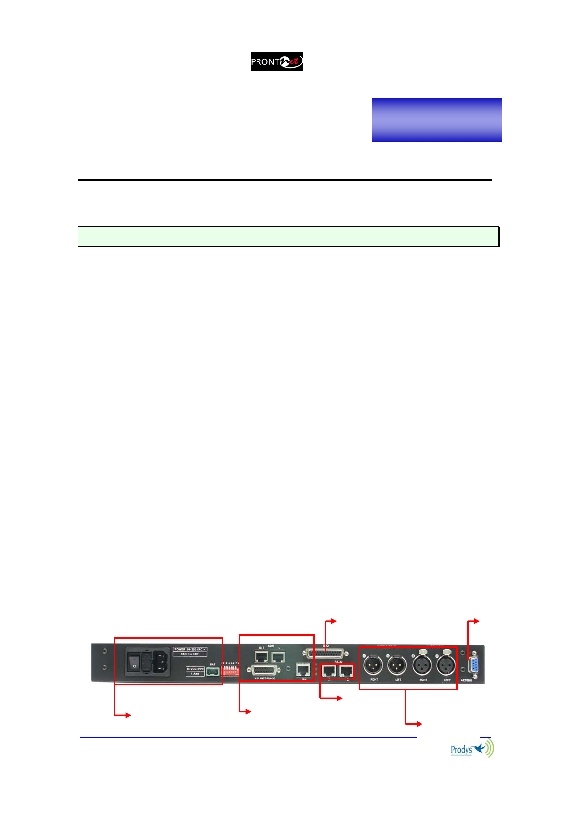
II.3 The rear panel
The majority of the connections of the ProntoNet are found on the back panel.
They are grouped together according to their function, as below:
11
GPIO Port
AES/
EBU
Prontonet User’s Manual v410 9
Power
communication
interfaces
RS232
Port
Audio
(analog)
II.3.1 Power
On the back panel you will find the main power inlet. You will also find the main
power switch and the fuse holder. The ProntoNet unit is designed to take AC
universal power, from 100 to 240 VAC with frequency between 50Hz and 60Hz.
You will also find a fuse holder that holds two fuses, one for each phase of input.
When it is necessary to replace either fuse, it is important to make sure that it
complies with the technical specifications outlined below that will ensure
adequate protection.
Fuse requirements:
Fuse type: Type T
Amps 2A
Power 250V
ATTENTION – CHANGING THE FUSE
Disconnect the power cable BEFORE changing the fuse.
24 VDC SECONDARY POWER SOURCE
THIS IS OPTIONAL AND DOES NOT COME FITTED AS STANDARD.
The unit will switch automatically from the primary power source to the
back-up power source in the event of a cut in the primary power supply.
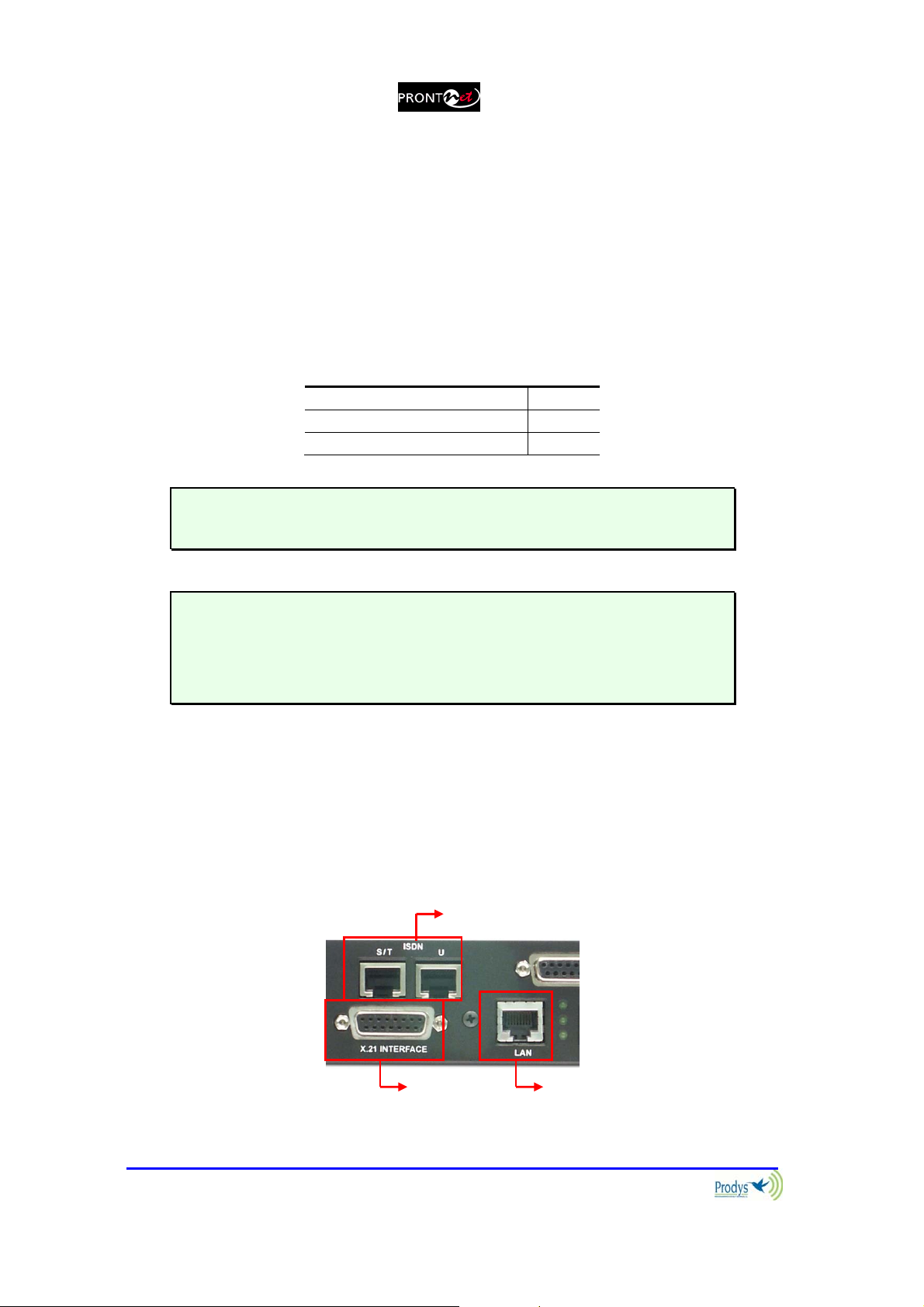
II.3.2 Communication Interfaces
The ProntoNet is equipped with three different communication interfaces –
Ethernet, ISDN and X21. These are all accessed on the rear panel, as shown in
the following diagram:
ISDN
Prontonet User’s Manual v410 10
LAN Ethernet X21

II.3.2.1. Ethernet port – the LAN Connector
The LAN socket is an standard 100Base-Tx (10/100 Mbps) Ethernet connection
that takes the typical RJ45 plug. Through this Ethernet port it is possible to
transmit and receive audio, as well as manage the equipment. Next to the
socket there are three LEDs that indicate different states for the connection and
these are very useful in problem-solving situations.
LAN LED’s:
Connection to a Hub or Switch
In the majority of cases you can simply connect the unit’s LAN port to your
Ethernet network’s Hub or Switch using an Ethernet cable (CAT5). In this
case you should use a standard ‘straight-through’ Ethernet cable (not a
‘cross-over’ cable). This kind of cable can normally be found in any IT shop.
In any case, this cable is described in more detail below:
Connection to a PC
In some cases, such as when you configure the equipment, it is possible
that you will want to connect the unit directly to a PC. In this case the PC
must have a free Ethernet port to connect to and you must use a ‘crossover’ Ethernet cable. Again, any good IT shop will stock these cables. This
time the wiring is as follows:
Prontonet User’s Manual v410 11
II.3.2.2. ISDN Port
The ProntoNet incorporates an ISDN terminal adapter that allows connection to
a basic ISDN line (2B+D). It supports different ISDN protocols (EURO_ISDN,
DMS100, AT&T 5ESS and NAT1). To connect there are two RJ45 connectors: one
for connecting to an S/T interface and the other for connecting to a U interface.
Pin S/T Connector U Connector
1
2
3
4
5
6
7
8
NC NC
NC NC
Tx + NC
Rx+ RING
Rx- TIP
Tx- NC
NC NC
NC NC
The U connector is only available if an NT1 interface is installed.
The NT1 interface is optional and is not supplied as standard.
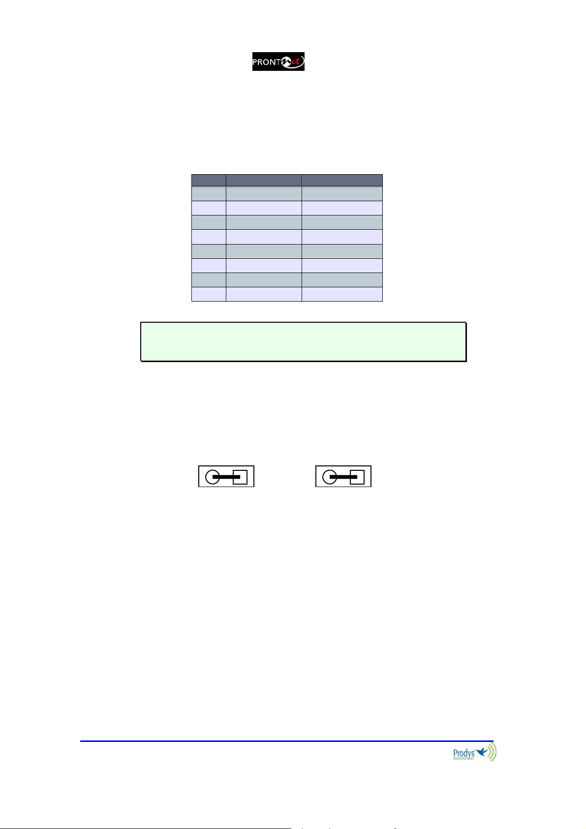
When the ProntoNet is connected to a basic rate interface with bus configuration
and the unit is the termination point, it must be loaded with 100 Ohm resistors.
These may be already fitted in the connection socket, if you do not have external
termination, the ProntoNet has jumpers available internally that can be set to
terminate the ISDN line. The jumpers are found next to the RJ45 connectors.
P2 P3
100Ω RESISTORS CONNECTED
Prontonet User’s Manual v410 12
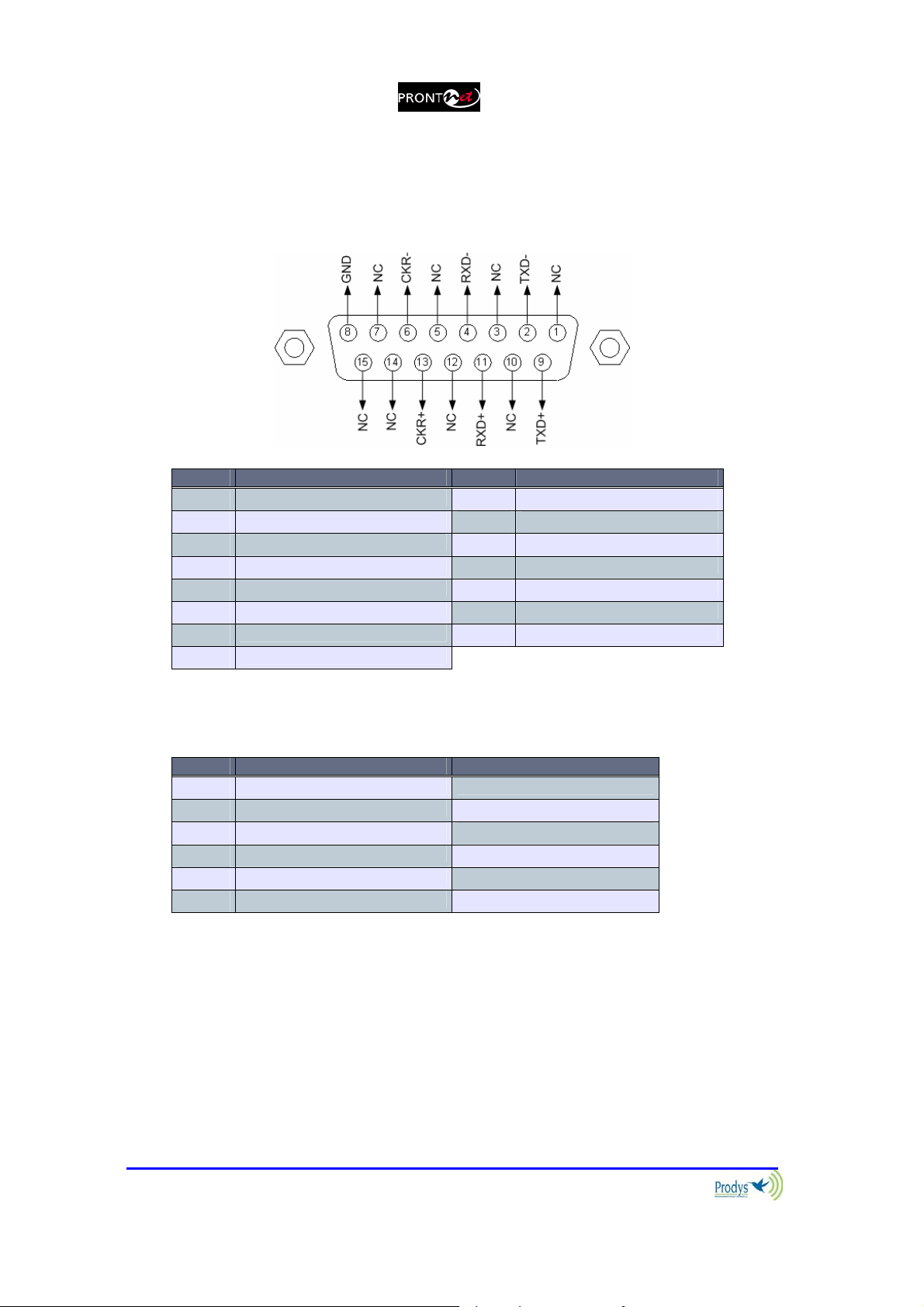
II.3.2.3. X21 Port
The X21 Port allows the transmission and reception of audio via a dedicated
digital connection. The socket is the standard 15-pin X21 subD with the
following connections:
Pin Function Pin Function
1 NC 9 Transmit Data TxD+
2 Transmit Data TxD- 10 NC
3 NC 11 Receive Data RxD+
4 Receive Data RxD- 12 NC
5 NC 13 Clock +
6 Clock - 14 NC (Internally used)
7 NC (Internally used) 15 NC
8 GND
To connect a V35 port one must bear in mind the following correlation between
signals:
Pin X21 ProntoNet V35 Signal
2 Transmit Data TxD- P
9 Transmit Data TxD+ S
4 Receive Data RxD- R
11 Receive Data RxD+ T
6 Clock - V
13 Clock+ X
Prontonet User’s Manual v410 13
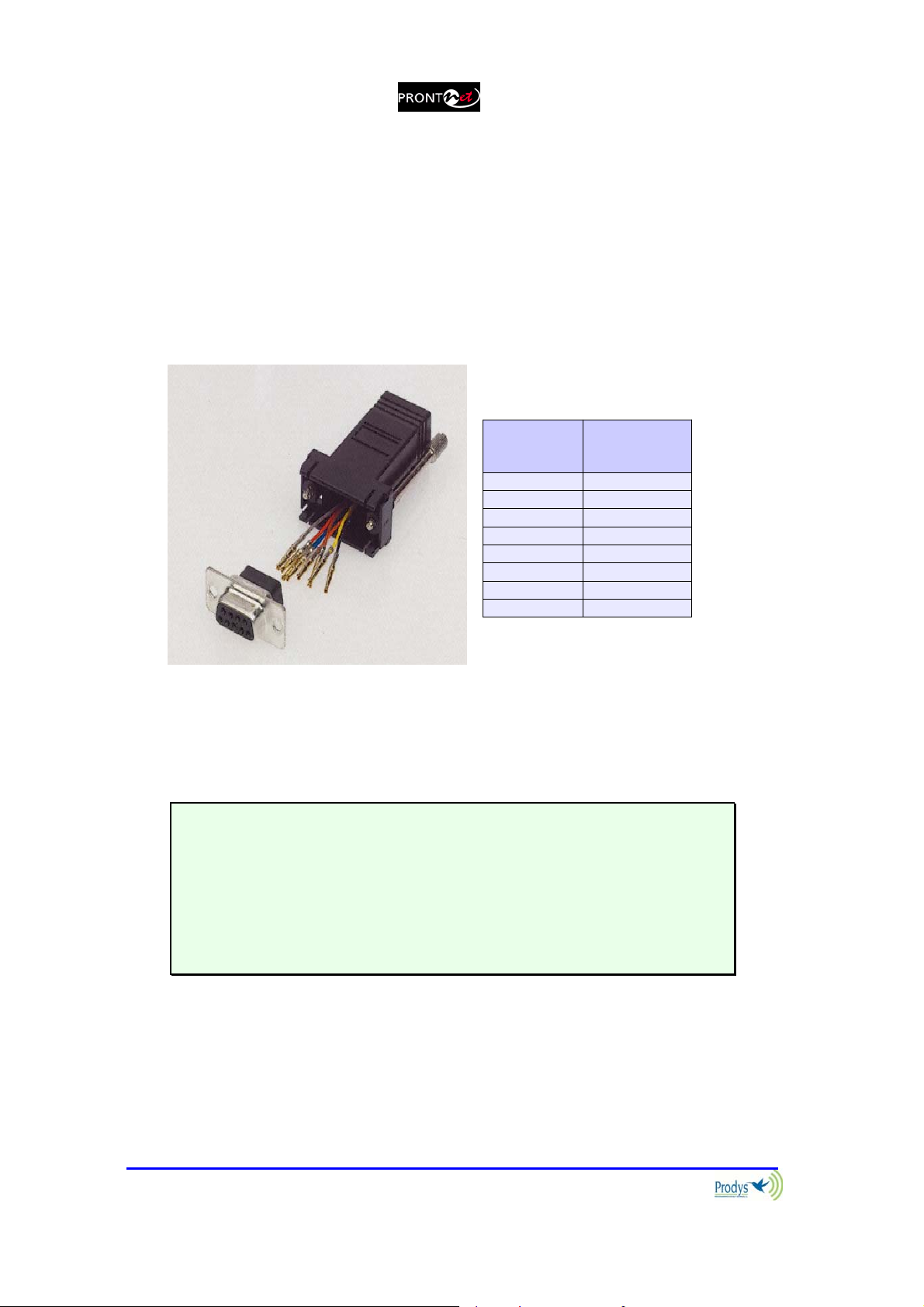
II.3.3 RS 232 Ports
There are two RS232 ports for use as auxiliary data ports. These ports allow the
transmission and reception of data along with encoded audio. Port A is always
ready. Port B is only available if the ProntoNet is configured as a DUAL Codec,
therefore able to operate two totally independent communication channels. Note
that these sockets are RJ45 connections, as opposed to the typical 9-pin subD
connections. To make the conversion between RJ45 and RS232 there are
modular connectors available that should be wired as follows:
S-Cluster
RJ45
Connector
1 (NC) 1
2 (Rx) 3
3 (GND) 5
4 (NC) 4
5 (NC) 6
6 (GND) 7
7 (Tx) 2
8 (NC) 8
1,4,5,8 must be unconnected
9-pin female
D-sub
Connector
The ports are always set to 8 DATA bits, NO parity, 1 START bit and 1 STOP bit.
The bit rate can be adjusted to between 300 and 9600 bps via software.
The ProntoNet acts as a DCE device, therefore the connection to each of the
RS232 ports is wired in the following way:
ProntoNet – Pin 7 connector RJ45.........................Pin 2 PC
ProntoNet – Pin 2 connector RJ45.........................Pin 3 PC
ProntoNet – Pin 3,6 connector RJ45......................Pin 5 PC
The ProntoNet ignores hardware handshaking signals.
Prontonet User’s Manual v410 14
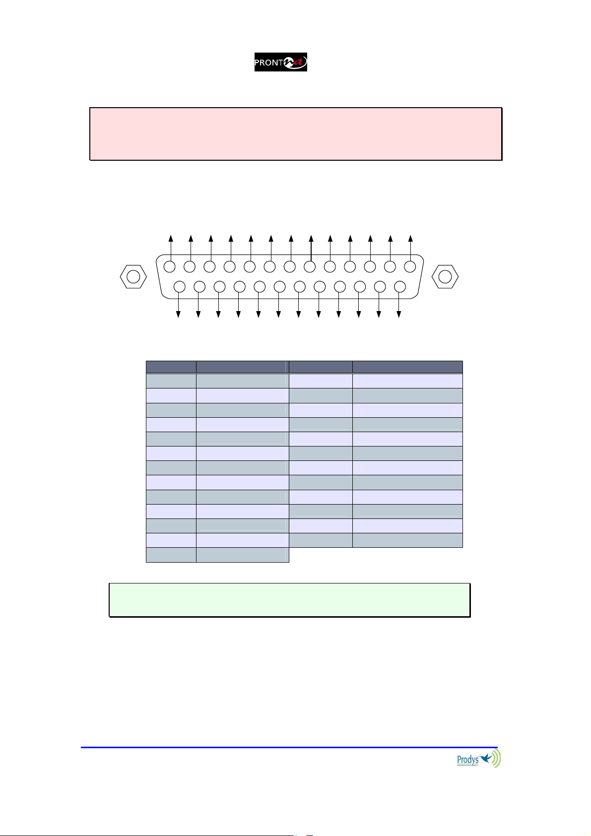
II.3.4 GPIO Port
WARNING
GPIO has been modified in ProntoNet with serial number 8938/00250 or higher.
Since this production, the GPIO is provided with 7 inputs and 7 outputs.
A subD 25 pin socket provides a general purpose connection with 7 inputs and 7
outputs. The connections must be wired according to the following diagram:
NC
NC
OUT1
OUT3
OUT5
9 678
10111213
25 24 23 22 21 14
NC
NC
OUT2
OUT4
OUT6
OUT7
GND
GND
NC
NC
NC
NC
IN2
IN4
IN6
VCC
12345
1617181920
15
IN1
IN3
IN7
IN5
Pin Function Pin Function
1
2
3
4
5
6
7
8
9
10
11
12
13
+5VDC 14 IN 7
IN 6 15 IN 5
IN 4 16 IN 3
IN 2 17 IN 1
NC 18 NC
NC 19 NC
GND 20 GND
OUT 7 21 OUT 6
OUT 5 22 OUT 4
OUT 3 23 OUT 2
OUT 1 24 NC
NC 25 NC
NC
Pin 1 is connected to +5 volts. If you need it , run this power supply through
your device with a resistor in series to limit the maximum current to 300 mA.
II.3.4.1. Inputs
The inputs are active for grounding (active low).
Prontonet User’s Manual v410 15
II.3.4.2. Outputs
The outputs are “open collector”. They allow an output of 5VDC on one pin to
facilitate interconnection with the outputs. Each output supports up to a
maximum of 40VDC / 40 mA and will require a pull-up resistor to function with
other logic inputs. An appropriate value is 2.2 Kohms.
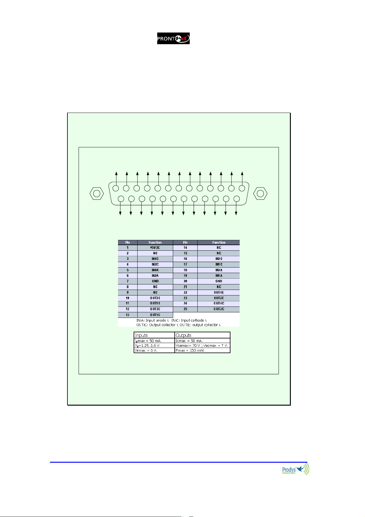
ProntoNet with serial numbers before than 8938/00250 are provided with the
following GPIO port
The GPIO port contains 4 opto-isolated inputs and outputs:
OUT6
OUT7
GND
GND
NC
NC
NC
NC
IN1
IN2
IN4
IN6
1617181920
15
IN5
IN3
NC
NC
OUT1
OUT3
OUT5
9 678
10111213
25 24 23 22 21 14
NC
NC
OUT2
OUT4
VCC
12345
IN7
Pin 1 is connected to +5VDC via a polyswitch resetable fuse and can be used
to provide power to an external circuit. The maximum current must not
exceed 300 mA.
Prontonet User’s Manual v410 16
II.3.5 Audio interfaces
II.3.5.1. Analog audio I/O
The analog audio I/O is connected through the XLR connections on the rear
panel. The wiring conforms to the following scheme:
Pin Función
1 Ground
2 Audio+
3 Audio-
These inputs and outputs are electronically balanced with a maximum
level of +22 dBu.
II.3.5.2. AES/EBU Interface
An AES/EBU interface is available via the subD 9 pin connector on the rear panel
of the unit. This connector provides the option to connect an externally
synchronised signal. The user can select via software if the digital output is to
synchronise with the audio input or with an external sync signal. The connector
is wired in the following way:
Pin Function Pin Function
1 AES/EBU IN - 6 AES/EBU IN +
2 GND 7 SYNC +
3 SYNC - 8 GND
4 GND 9 AES/EBU OUT +
5 AES/EBU OUT -
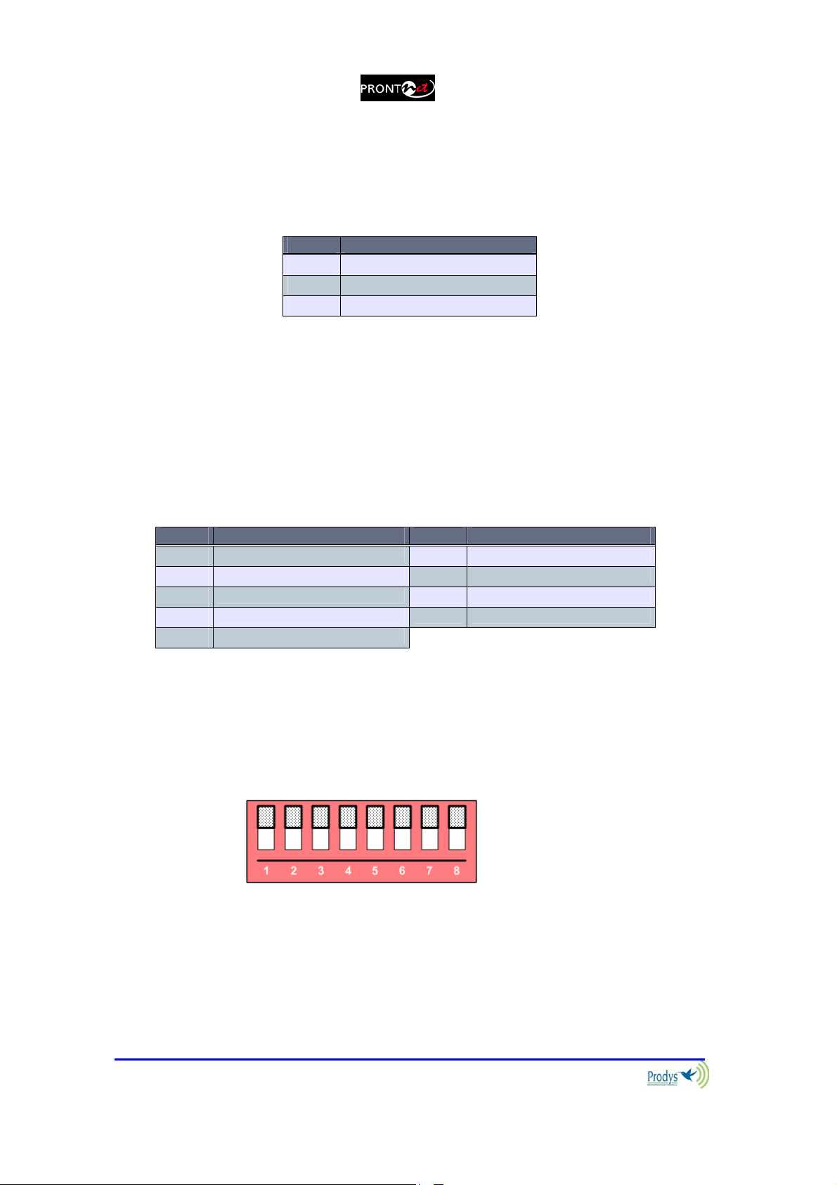
II.3.6 Microswitches
There are 8 microswitches on the back panel which are reserved for special
functions. Before turning on the unit the user must check that they are
configured according to the following diagram, which is the standard start-up
configuration:
Prontonet User’s Manual v410 17
Chapter III
The Front Panel
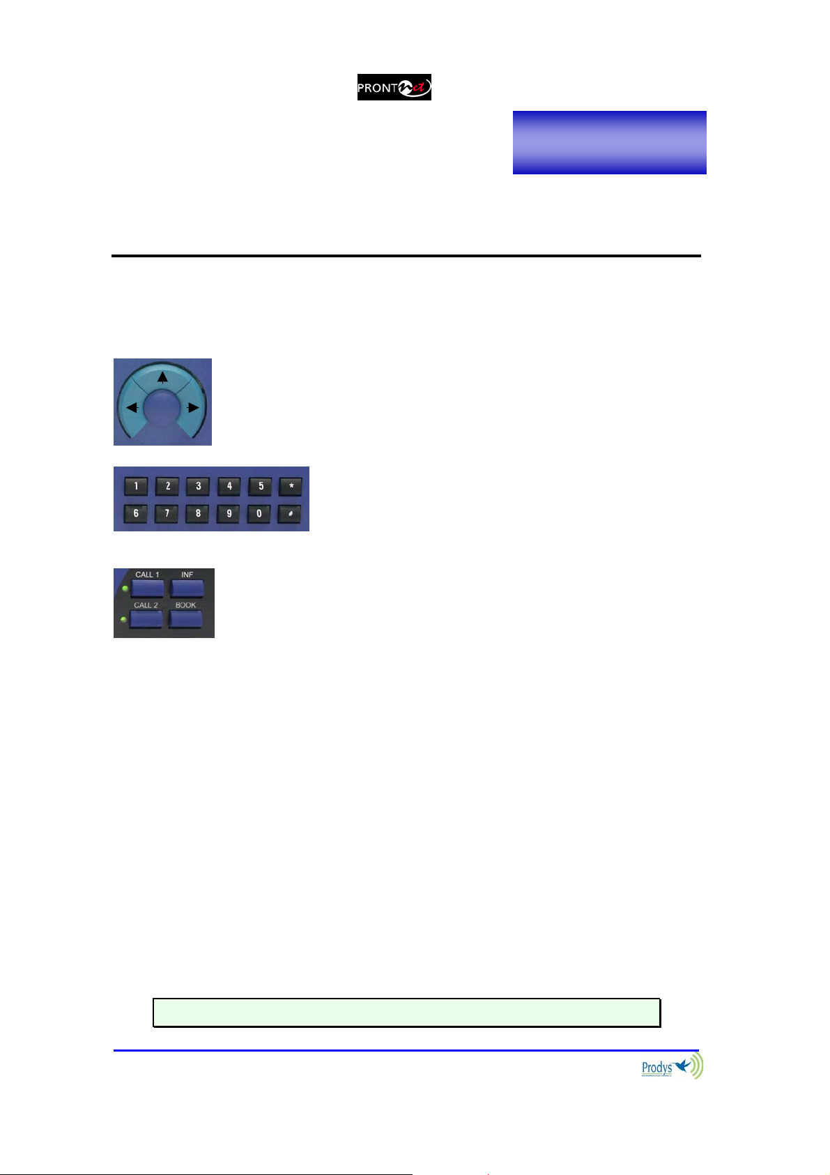
The front panel of the ProntoNet has a display and keypads that allow you to
control and configure the unit. The keys are laid out in the following manner:
o
OK
Navigation Keys: The keys ⇐ , ⇑ , ⇒ , are used for moving
around the menus and the OK is for selecting/accepting the
desired action or parameter.
Number keypad: This numeric keypad is for
entering information such as the IP address or ISDN
number that you wish to connect to.
CONTROL Keys: There are several special keys grouped
together:
CALL1 and CALL2 are for establishing and terminating
connections, and also to monitor the called/calling number.
INF is for viewing status information.
BOOK for establishing communications using a configuration
saved in the Address Book.
III.1 DISPLAY
To help explain the ProntoNet DISPLAY we should distinguish between the status
screen and the menu screen:
The status screen shows information about the communication lines and
the status of the Decoder.
The Menu screen shows the different configuration menu options and is
only displayed when you press OK on the navigation menu keys.
III.1.1 STATUS SCREEN:
This is the default screen that you will see when the ProntoNet is ‘at rest’, that is,
when you are not navigating or using the front panel keys. It reports the status
of the communications and the Decoder.
More information about this in the following sections.
Prontonet User’s Manual v410 18
(0)
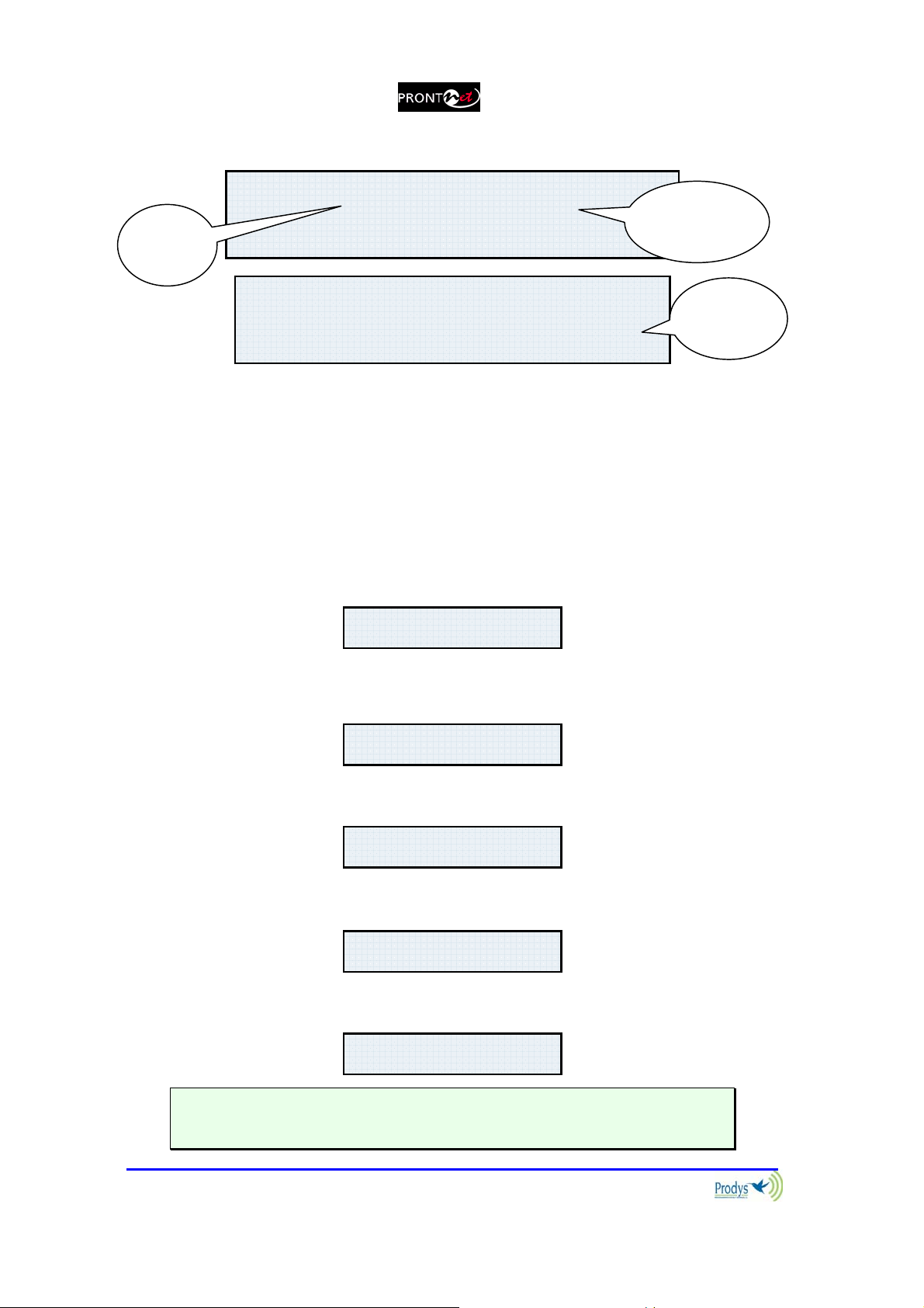
The display will show information in the following way:
Status
Line 1
L1¼ CONNECTED FRAMED
L2:IDLE
Status
Decoder 1
L1:IDLE (0) ISDN
L2:IDLE (0) BKUP ON
Backup
status
The first line shows information about the status of communication Line 1.
Followed by status information of the audio Decoder.
The second line shows information about the status of communication Line 2.
(This line will only be activated when ISDN is selected as the communication
interface.)
The communication lines will be in one of the following states:
DOWN: The communication line is not physically detected. Most likely the
interface is not plugged in. The Display shows “DOWN”:
L1:DOWN ISDN
L2:DOWN
IDLE: The line is detected physically but no connection is being made. The
display shows IDLE and the disconnection code:
L1:IDLE (0) ISDN
L2:IDLE
CONNECTED: The line is connected. The display shows “Connected” and
the Decoder status:
L1:CONNECTED FRAMED
L2:DOWN
CALLING: In the process of making a connection. The display shows an
arrow indicating outgoing calling and the ISDN number or IP address:
L1:Æ1234567890
L2:DOWN
RING: Receiving a call on the line. The display shows an arrow indicating
incoming calling and the ISDN number or IP address:
L1:Å1234567890
L2:DOWN
Each Key has an associated LED that indicates the following situations:
LED off: Line disconnected
Prontonet User’s Manual v410 19
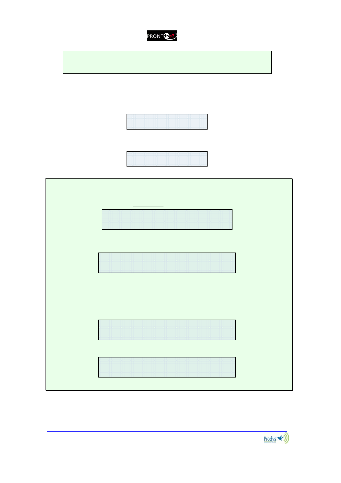
LED on: Line connected
LED blinking: Call in progress or incoming call detected
The Decoder can be in one of the following states:
FRAMED: Audio Synchronised. The displays shows the word “FRAMED”:
L1:CONNECTED FRAMED
L2:DOWN
SEARCH Searching for synchronisation. The displays shows the word
“SEARCH”:
L1:CONNECTED SEARCH
L2:DOWN
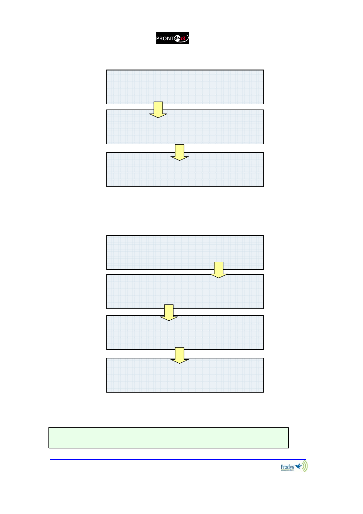
The Decoder status information only appears if the line is connected
If the line is showing an IDLE status, an indicator code will show the cause of the
last disconnection below. In Appendix B you will find explanations for each of these
codes.
L1:IDLE (0) IP
L2:NOT AVAILABLE
When the lines are not connected the selected NET will be shown.
L1:IDLE (0) IP
L2:NOT AVAILABLE
When the ProntoNet is operating as a DUAL codec, there will be two independent
Decoders, one for each line. In all other cases information will only show on the first
line of the display as there will be only one Decoder working (even if there are two
communication lines connected).
L1:IDLE (0) IP
L2:NOT AVAILABLE
When the lines are connected the direction of the arrow will indicate if the unit made
or received the connection.
L1´ CONNECTED FRAMED
L2: NOT AVAILABLE
The backup can be in one of the following states:
DISABLED: The display doesn’t show any information about it.
Prontonet User’s Manual v410 20

(10)
(10)
BKUP OFF: The backup is enabled but not activated, that is, the main line is
working appropriately.
L1:CONNECTED FRAMED
L2:--- BKUP OFF
TDWN: The main line is dropped and the display shows the countdown of
the timer.
L1:CONNECTED SEARCH
L2:--- TDWN=20
BKUP ON: The ProntoNet is working in backup mode, that is, transmitting
and receiving through the ISDN.
L1:CONNECTED FRAMED
L2:IDLE
BKUP ON
TUP: The main line is working well again and the display is showing the
countdown of the timer before of leaving the backup mode.
L1:CONNECTED FRAMED
L2:IDLE
TUP=10
Prontonet User’s Manual v410 21

III.2 Control Keys:
III.2.1 The CALL 1 and CALL 2 keys
The fundamental role of these keys is the initiation and termination of a
connection. Note that the keys have different functions depending on the
communication line status at any given moment. Additionally, the display will
also show different information depending on the type of NET selected - IP,
ISDN or X21.
Depending on the line’s status, CALL 1 and CALL 2 will function in the following
way:
With the line disconnected:
a) Initiation of a communication
access the call initiation menu. Depending on the type of NET
selected (IP, ISDN or X21) the dialog that you will see will vary.
(Note that, CALL 2 only works when ISDN is selected as the
NET).
b) Connecting to an incoming call
to manual answering, the CALL 1 or CALL 2 keys will connect the
line when an incoming call is detected on the respective lines.
With a line connected: There are two distinct functions:
a) A short press
the current connection.
b) A long press
will display on-screen the number or IP address of
(over 1 second) will disconnect the associated line.
: Pressing CALL 1 or CALL 2 will
: if the ProntoNet is pre-configured
It is posible to program a number of call retries from the ProntoNet web page.
III.2.1.1. Establishing a call when ProntoNet is configured as an IP codec
(NET = IP)
If an IP network is selected, pressing CALL 1 will display the following:
The user must select beforehand if the IP communication type is MULTICAST
mode (point to multi-point) or UNICAST mode (point to point). Next, depending
on the selected option will show:
LAN L1 MODE
{MULTICAST} UNICAST
Prontonet User’s Manual v410 22
K
K
KOKOK
MULTICAST Æ
{MULTICAST} UNICAST
LAN L1 MODE
O
LAN L1 MODE
LAN L1 DIAL
{Tx} Rx
O
10.0.0.0
To make the connection press OK. “Period” is selected with the # key.
UNICAST Æ
MULTICAST {UNICAST}
LAN L1 MODE
O
LAN L1 MODE
{UNIDIR} BIDIR
LAN L1 MODE
{Tx} Rx
LAN L1 DIAL
10.0.0.0
To make the connection press OK. “Period” is selected with the # key.
CALL2 key is available from version 3.3.1 in order to establish a second unicast
TX communication, sending the same audio as in line 1.
Prontonet User’s Manual v410 23

III.2.1.2. Establishing a call when ProntoNet is configured as an ISDN codec
(NET = ISDN)
Pressing the CALL 1 key will display the page where you can enter the number to
be called on Line 1. The CALL 2 key does the same for Line 2.
III.2.1.3. Establishing a call when ProntoNet is configured as an X21 codec
(NET = X21)
ISDN L1 DIAL
123456789012345
ISDN L2 DIAL
123456789012345
When ProntoNet is set up for dedicated lines (NET = X21) it is not necessary to
talk about establishing connections in the same way as we have been doing with
IP networks and ISDN. In reality, the CALL 1 key simply enables or disables
communication via the X21 port. The CALL 2 key does nothing as there is only
one X21 port available.
To connect the Line in X21 press CALL1. To disconnect the line press
CALL1 over 1 second.
Each Key has an associated LED that indicates the following situations:
LED off: Line disconnected
LED on: Line connected
LED blinking: Call in progress or incoming call detected
Prontonet User’s Manual v410 24

III.2.2 The INF key
This key allows the user a simple and quick way to display detailed information
on the status and configuration of the ProntoNet. Given that the screen is not
able to display all the information at once, you can cycle through the different
information screens by repeatedly pressing the INF button. These screens are:
1. Audio input VU meters.
2. Audio output VU meters.
3. Decoding algorithm.
4. Encoding algorithm.
5. IP configuration parameters.
6. General configuration: NET type selected (IP, ISDN o X21), audio
input, etc.
7. GPIO status.
Looking at each one in detail.
III.2.2.1. Screen 1: Audio input VU meters
The audio input levels are represented on-screen horizontally over 18 characters.
Each character represents 3dB. All characters showing will represent 0 dBFs.
When only one character is showing it therefore represents a value between –96
and –56 dBFs. From version 3.3.1 on, the dBFs value is indicated.
L:>>>>>>
R:>>>>>
III.2.2.2. Screen 2: Audio output VU meters
From version 3.3.1, the audio output vu meters can be monitored from
the front panel display, in the same manner as with the input vu
meters.
Prontonet User’s Manual v410 25
III.2.2.3. Screen 3: Decoding algorithm
This window shows the algorithm that is selected and synchronised for Decoder
1 and 2 (number 2 is only relevant when ProntoNet is working as a DUAL codec).
Here are some examples:
.
If the Decoder is not synchronised it will show the text “SEARCHING”
The different algorithms are written in the following way:
PCM – Mode - Fs – number of bits.
G711 – Law.
G722.
MPEG Layer II – Bit rate – Mode – Fs – CRC.
MPEG Layer III – Bit rate – Mode – Fs – CRC.
AAC MPEG2 LC – Mode – Fs – CRC.
AAC MPEG4 LC – Mode – Fs – CRC.
AAC MPEG4 LD – Mode – Fs – CRC.
aptX – Mode.
D1:MPL2-064-MN-48
D2:G722
D1:MPL2-64-ST-48
D2:NOT AVAILABLE
III.2.2.4. Screen 4: encoding algorithm
This is similar to the Decoder described above, but will describe the encoding
algorithm instead.
The different algorithms are displayed in the same way as the Decoder outlined
above, except for the following modes:
AAC MPEG2 LC – Bit rate – Mode – Fs – CRC.
AAC MPEG4 LC – Bit rate – Mode – Fs – CRC.
AAC MPEG4 LD – Bit rate – Mode – Fs – CRC.
Prontonet User’s Manual v410 26
E1:MPL2-64-MN-48-CR
E2:G722

If the Encoder is configured to automatic mode or if the Decoder is not
synchronised you will see the following:
III.2.2.5. Screen 5: LAN port configuration parameters
Here we see the IP address and mask.
III.2.2.6. Screen 6: General configuration
This shows the NET type and the audio input selected. Here are two such
examples:
a) NET = IP and analog audio input:
b) NET = ISDN and digital audio input with external sync:
E1:AUTO
E2:NOT AVAILABLE
ADDR:192.168.100.100
MASK:255.255.255.000
CODEC IP
AUDIO IN: ANALOG
CODEC ISDN
AUDIO IN: DIG - EXT
III.2.2.7. Screen 7: GPIO
This represents the GPIO status:
Prontonet User’s Manual v410 27
GPI:0000
GPO:1010

III.2.2.8. Screen 8: IP connections
III.2.3 The BOOK Key
This key directly accesses the internal Address Book. By pressing this key we can
view and connect to entries in the Address Book. (note that to edit or modify
entries we must go instead to the BOOK option in the main menu). For making
connections however, the BOOK key works like this:
Pressing BOOK you enter the Address Book index:
Using the left and right navigation keys you can go through the different entries
in the Address Book index. By pressing OK we select the item that is on-screen.
Now the screen shows the number/numbers to call, or the IP address, depending
on which has been saved.
Pressing OK again will process this information, that is, the ProntoNet will
configure the Encoder according to the BOOK entry and make the connection
over ISDN or IP. However, if you press the right arrow instead you can simply
display the encoding mode saved.
IP1:MULTICAST RX
IP2:NOT AVAILABLE
<< BOOK[01] >>
L1:1234567890
L2:1234567890
E1:MPL3-128-MN-48
When you press the BOOK key you will only be shown stored entries that
are relevant to the NET that is currently activated. So when NET = ISDN,
you will only be able to browse previously stored ISDN entries, just as
when NET = IP you will only be able to select from relevant IP addresses.
Prontonet User’s Manual v410 28

Chapter IV
THE MENU
By pressing OK on the navigation keys you enter the system’s main menu
from the default STATUS screen. We shall take a close look at the different
options available in the system menu. To aid in this, we recommend the reader
to have to hand the hierarchical menu tree in the appendices of this manual.
IV.1 The Controls: Navigation keys
Using the on-screen menus the user can control all the functions of the
ProntoNet. Using the ⇐, ⇑ and ⇒ keys it is possible to move around the system
menus and with the OK key select the desired options. Here is some more detail
on each of these keys:
⇒ : Moves to the menu option on the right. When we reach the last option, a
further press of this right arrow will cycle us round again to the first option, i.e.
we go to the left-most end of the list. The option that is available for selection
will appear on the display inside brackets ( {} ).
⇐ : Moves to the menu option on the left. When we reach the first option, a
further press of this left arrow will cycle us round again to the last option, i.e. we
go to the right-most end of the list. The option that is available for selection will
appear on the display inside brackets ( {} ).
⇑ : Returns to the previous level of the menu. If we keep pressing this key we
will leave the system menu completely and return to the STATUS screen.
OK : This selects or confirms the option that is selected (between the brackets)
and where relevant activates the subroutine associated with this option.
IV.2 Main Menu:
The main menu has the following options:
NET: This allows us to select the communications port required.
ENC: Here you can configure Encoders 1 and 2
CONF: Here you can configure various general parameters of the unit, for
instance selecting the audio input or setting up the LAN port.
INF: From here you can obtain information on the software version and
various configuration parameters of the ISDN port.
Prontonet User’s Manual v410 29
{NET}ENC CONF INF
MAIN MENU

IV.3 NET: Selecting a communications port.
The ProntoNet has three different communication ports that allow the unit to
operate over three distinct types of network: IP, ISDN and dedicated digital
networks (X21 port).
The NET option is only available if the lines are not already connected. If they
are busy, the display will show the following text:
Each NET type selection will of course have their own set of configuration
parameters, as will be seen next.
NET SELECTION
{IP}ISDN X21
NOT AVAILABLE WITH
LINE CONNECTED
IV.4 ENC: Encoder algorithm selection menu
From this option we can choose the audio Encoder algorithms. Note that the
ProntoNet can operate as a DUAL codec when ISDN is selected as the
communications interface. In this case, it is possible to have two simultaneous
communications that are totally independent and so it is possible to configure the
second Encoder. However, there are operational restrictions in the configuration
of Encoder 2 that depend on the algorithm and mode already selected for
Encoder 1. In chapter VI these restrictions are described in more detail.
If we select ENC from the main menu the following is displayed:
The ENCODER 2 option is only available if NET = ISDN.
IV.4.1 Configuration of Encoder 1:
The configuration of Encoder 1 (and Encoder 2 where available) is done in
stages, starting with the selection of an algorithm and following on with the
different parameters that relate to that particular algorithm. The ProntoNet menu
will always only display the options and parameters that are relevant to each
algorithm’s configuration. Additionally there are certain restrictions associated
SET ENCODING MODE
{ENCODER1}ENCODER2
Prontonet User’s Manual v410 30
 Loading...