

Page 1
Nov 08
Rev. 6.0
Page 2

Prodys S.L. Tel: +34 91 6896880 Θ Fax: +34 91 6943777 Θ Email: [email protected] Θ Web: www.prodys.com
Page 2
Index
Index..................................................................................2
Introduction ........................................................................6
I.1 The set of Manuals .................................................................. 6
I.2 Application Notes ................................................................... 7
I.3 The User Manual..................................................................... 7
Web Browser Control .............................................................9
Quick Start........................................................................ 18
III.1 Selection of the network interface and protocol ............................19
III.2 Selection of the network profile ...............................................20
III.3 Selection of the Encoder algorithm ............................................ 21
III.4 Dialling the destination codec ..................................................22
III.5 Stopping a communication ......................................................23
III.6 Encoder and Decoder status indication........................................23
III.7 Decoder Status .................................................................. 24
Configuration..................................................................... 25
IV.1 Interfaces ..........................................................................26
IV.1.1 LAN port .......................................................................26
IV.1.2 Ports............................................................................29
IV.1.3 SNMP configuration ..........................................................31
IV.1.4 Ethernet Port Configuration ................................................32
IV.1.5 ISDN Terminal Adaptor configuration ..................................... 33
IV.1.6 X21 Port:.......................................................................34
IV.1.7 RS232 Ports....................................................................35
IV.1.8 GPIO Port ......................................................................35
IV.1.9 Audio Configuration.......................................................... 39
IV.2 System Configuration ............................................................41
IV.2.1 TimeDate ...................................................................... 43
Page 3
Prodys S.L. Tel: +34 91 6896880 Θ Fax: +34 91 6943777 Θ Email: [email protected] Θ Web: www.prodys.com
Page 3
IV.2.2 Password.......................................................................44
IV.2.3 Aux Data .......................................................................44
IV.2.4 Software Versions ............................................................46
IV.2.5 Alarm paging ..................................................................46
IV.2.6 Net Backup .................................................................... 48
IV.2.7 Device Backup ................................................................48
IV.2.8 License.........................................................................48
IV.3 Book index .........................................................................50
IV.4 Scheduler ..........................................................................51
IV.4.1 Enabling and disabling the Scheduler .....................................52
IV.4.2 Automatic and manual call .................................................52
IV.4.3 Programming the scheduler.................................................52
IV.4.4 Scheduled call configuration ...............................................55
IV.4.5 Manual configuration ........................................................55
IV.4.5.1. Automatic configuration from the phone book .......................56
IV.4.6 Modifying existing scheduled calls......................................... 57
IV.4.7 Deleting existing scheduled calls ..........................................57
IV.4.8 Copying and pasting scheduled calls ......................................57
IV.4.9 Monitoring scheduled calls.................................................. 58
IV.5 Advanced Configuration .........................................................59
IV.6 Streaming ..........................................................................60
IV.6.1 Protocols.......................................................................60
IV.6.2 Proprietary Protocol (V1) ...................................................61
IV.6.3 Proprietary Protocol (V2) ...................................................61
IV.6.4 Proprietary Protocol (V3) ...................................................62
IV.6.5 CCS NetStar /AudioStar protocol...........................................62
IV.6.6 RTP protocol ..................................................................63
IV.6.7 SIP ..............................................................................63
IV.6.8 SAP .............................................................................65
IV.6.9 Profiles for audio streaming over IP Networks ...........................68
IV.6.10 Tx .............................................................................68
IV.6.11 Rx .............................................................................71
IV.6.12 Test ...........................................................................72
IV.6.13 Real Time Analyzer .........................................................75
IV.7 Call Log.............................................................................76
IV.8 Alarms ..............................................................................78
IV.8.1 Selecting Alarms..............................................................78
IV.8.2 Monitoring Alarms ............................................................81
IV.8.2.1. Alarms History .............................................................81
Page 4
Prodys S.L. Tel: +34 91 6896880 Θ Fax: +34 91 6943777 Θ Email: [email protected] Θ Web: www.prodys.com
Page 4
How does Prodys IP Family of codecs work? .............................. 83
V.1 Selecting the network interface ................................................83
V.2 Configuration parameters that are dependant on the network type
selected .................................................................................84
V.3 Prodys IP Family codec working as a “DUAL CODEC” over ISDN ............85
V.4 Prodys IP Family codec working as a “Double CODEC” over IP ............. 86
V.5 About how the Decoder works and automatic searching .................... 89
V.6 The Prodys codec operating over IP (Prodys Proprietary Protocols)....... 91
V.6.1 UNICAST communications....................................................91
V.6.2 MULTICAST communication.................................................. 91
V.6.3 MULTI-UNICAST................................................................ 94
V.6.4 More about Prodys Proprietary Protocols.................................. 96
V.6.5 More about Prodys Proprietary Protocol v2 ...............................96
V.6.6 More about Prodys Proprietary Protocol v3 ...............................98
V.6.7 IP ports for Prodys Proprietary protocols V1 & V2 .......................99
V.6.8 IP ports for Prodys Proprietaty protocols V3............................ 100
V.6.9 SIP (EBU TECH 3326 standard for audio over IP)....................... 101
V.6.9.1. Enabling SIP protocol for Prodys IP codecs .......................... 101
V.6.9.2. Configuring SIP ........................................................... 102
V.6.9.3. Public IP Address......................................................... 103
V.6.9.4. SIP Server Registration.................................................. 104
V.6.9.5. Calling with SIP .......................................................... 105
Peer to peer SIP calls ....................................................... 106
Calls through SIP Proxy Server............................................. 106
V.6.10 Table of ports .............................................................. 107
V.6.11 Ports definition ............................................................ 108
V.6.11.1. Management Ports ..................................................... 108
V.6.11.2. Streaming and Audio Control Ports .................................. 109
V.6.12 Examples of used ports for Prodys Proprietary Protocols............ 111
V.6.13 Examples of used ports for SIP Protocol................................ 112
V.6.14 Port Configuration......................................................... 112
V.6.14.1. Port Configuration for management ports.......................... 112
V.6.14.2. Port Configuration for Streaming and control audio ports ....... 113
Port configuration for Prodys Proprietary Protocol V1 & V2 .......... 113
Port configuration for Prodys Proprietary Protocol V3 ................ 113
V.6.14.3. Port configuration for SIP Protocol .................................. 114
V.6.14.4. Port configuration for RTP Protocol ................................. 115
V.6.15 Router configuration ...................................................... 116
V.6.16 Examples of port setup for calling over IP ............................ 117
Page 5
Prodys S.L. Tel: +34 91 6896880 Θ Fax: +34 91 6943777 Θ Email: [email protected] Θ Web: www.prodys.com
Page 5
V.6.16.1. Different network topologies and port configuration............. 117
V.6.16.2. One-to-one topology................................................... 118
V.6.16.3. Array of codecs in a back-to-back configuration .................. 120
V.6.17 Other not audio network PROTOCOLS .................................. 126
V.6.18 PRODYS IPv4 addresses ................................................... 127
V.6.19 Forward Error Correction (FEC).......................................... 127
V.7 Prodys IP Family codec operating as an ISDN codec........................ 129
V.7.1 Establishing ISDN calls...................................................... 134
V.7.2 Receiving calls via ISDN .................................................... 135
V.7.3 Restrictions in ISDN communications..................................... 135
V.8 Prodys IP Family codec operating as an X21 codec......................... 137
V.9 Net Backup function ............................................................ 138
V.9.1 Net Backup MASTER Configuration ....................................... 138
V.9.2 Net Backup SLAVE Configuration.......................................... 140
V.10 Device Backup function ....................................................... 142
V.11 Addition of the codecs to be monitored.................................. 144
V.11.1 Protection switch N+1 by the Device Backup codec.................. 145
Technical Specifications ..................................................... 147
VI.1 Compression ..................................................................... 147
VI.1.1 BANDWIDTH (KHz) .......................................................... 147
VI.2 IP Protocols and compatibility................................................ 151
Disconnection Codes.......................................................... 152
Updating the firmware ....................................................... 154
Page 6
Prodys S.L. Tel: +34 91 6896880 Θ Fax: +34 91 6943777 Θ Email: [email protected] Θ Web: www.prodys.com
Page 6
INTRODUCTION
Prodys IP Family codec stands for a large range of compatible audio codecs from
Prodys. Those codecs allow applications as dual and multi audio codec by
supporting MPEG 2/4 AAC LC, MPEG 4 LD & HE and apt-X
TM
amongst other
standard algorithms, as well as bidirectional uncompressed audio transmission
over IP.
A Prodys IP Family codec is also a Multi-network audio codec that can be used
for audio streaming over a suite of communication networks:
ISDN 1-BRI (U or S/T interfaces)
1
.
X21 synchronous data transmission links (Digital Leased Line: DLL)
2
.
LAN connector, 10/100Base-T Ethernet interface for audio transmission and
control (audio streaming over private IP networks or Internet).
PSTN connector, to connect to Public Switched Telephone Networks
3
.
I.1 The set of Manuals
The User Manual is applicable to most of the common features provided by the
Prodys IP Family codec.
For some specific features or restrictions, the user is referred to the proper
Hardware and Reference Manual applicable to the codec in use. Installation
1
For some Prodys IP Family Codecs ISDN network capability is an option (Terminal Adapter
module). Please refer to the proper Hardware and Reference Manual for this point.
2
For some Prodys IP Family Codecs X21 network capability is an option (Terminal Adapter
module). Please refer to the proper Hardware and Reference Manual for this point
3
Only available on NomadaIP.
Chapter I
Page 7
Prodys S.L. Tel: +34 91 6896880 Θ Fax: +34 91 6943777 Θ Email: [email protected] Θ Web: www.prodys.com
Page 7
requirements, physical and electrical parameters are also included in this
document.
Hardware and Reference Manuals are available for:
ProntoNet
ProntoNet LC
ProntoNet IP Decoder
Nereus
Nereus One
PortaNet
Nomada IP
If several Prodys IP Family codecs are managed by means of the ProdysControl
please refer to the ProdysControl Manual too.
Prodys IP codecs provide the user with a control protocol which allows the user
to develop customized management software. The control interface for this
protocol is either the RS232 serial port or the Ethernet port. For detailed
description please refer to the Prodys IP Family codec SDK User’s Manual.
I.2 Application Notes
For specific subjects, Applications Notes and release update (What is new,
Changelog…) the user is kindly referred to check our download area at
www.prodys.net
or contact [email protected].
I.3 The User Manual
The information of the User Manual is arranged in the following sections:
Chapter I – Introduction
This chapter lists the content of most of the documentation available at
Prodys.
Chapter II – The Web Browser Control
Prodys IP Family codec can be controlled from a Web Browser. This chapter
describes how to enable the User Interface to the codec.
Page 8

Prodys S.L. Tel: +34 91 6896880 Θ Fax: +34 91 6943777 Θ Email: [email protected] Θ Web: www.prodys.com
Page 8
Chapter III – Quick Start
This chapter is a quick guide aimed to let new user arrange his first audio
communication.
Chapter IV – Configuration
This chapter is a comprehensive manual for all configuration parameters.
Chapter V – How does the Prodys IP Family codec work?
This chapter is a practical guide to help in understanding just how the Prodys
IP Family codec works under different configurations. Singular application
examples are included.
Appendix A – Technical specifications
This appendix describes the technical specifications in common for all devices
of the Prodys IP Family.
Appendix B – Disconnection Codes
This appendix describes the meaning of the disconnecting codes showed on
the display.
Appendix C – Updating the firmware
This appendix describes how to update the Prodys IP Family codec firmware.
Page 9
Prodys S.L. Tel: +34 91 6896880 Θ Fax: +34 91 6943777 Θ Email: [email protected] Θ Web: www.prodys.com
Page 9
WEB BROWSER CONTROL
Prodys IP Family codec can be controlled remotely by using an Internet Explorer
web browser. The computer can be locally connected directly via a crossover
CAT-5 cable, sharing the same Ethernet switch with the codec’s LAN interface or
remotely via the Internet.
To access the Prodys IP Family codec from the Internet Explorer, enter the IP
address of the unit in the address bar. Keep in mind that the Prodys IP Family
codec factory IP address is 192.168.100.100 and it could be necessary to modify
the network configuration of the computer on which the web browser is running
the first time.
4
Installation Requirements
1.- Pentium 166 or higher.
2.- 64MB RAM minimum.
3.- Operating Systems:
Microsoft Windows XP, Microsoft Windows 2000,
Microsoft Windows NT 4.0 Service Pack 6 or higher,
Microsoft Windows Millennium Edition (ME), Microsoft Windows 98.
Microsoft Windows Vista.
4.- Microsoft Internet Explorer 5.0 or higher.
The screen resolution must be 1024x768 minimum.
4
Some Prodys IP Family codecs are provided with a front panel display and keyboard. For these
devices it is possible to set directly the proper IP configuration before gaining access by means of
the web browser. Please refer to the “HW and Reference Manual” of your codec for details.
Chapter II
Page 10
Prodys S.L. Tel: +34 91 6896880 Θ Fax: +34 91 6943777 Θ Email: [email protected] Θ Web: www.prodys.com
Page 10
The first time that the computer accesses the Prodys IP Family codec it is
necessary to install the software. The computer will show the following
window:
The unit is supplied with the following IP address: 192.168.100.100
Please refer to the Hardware and Reference Manual if the IP address is unknown.
A procedure to recover the factory default configuration is described.
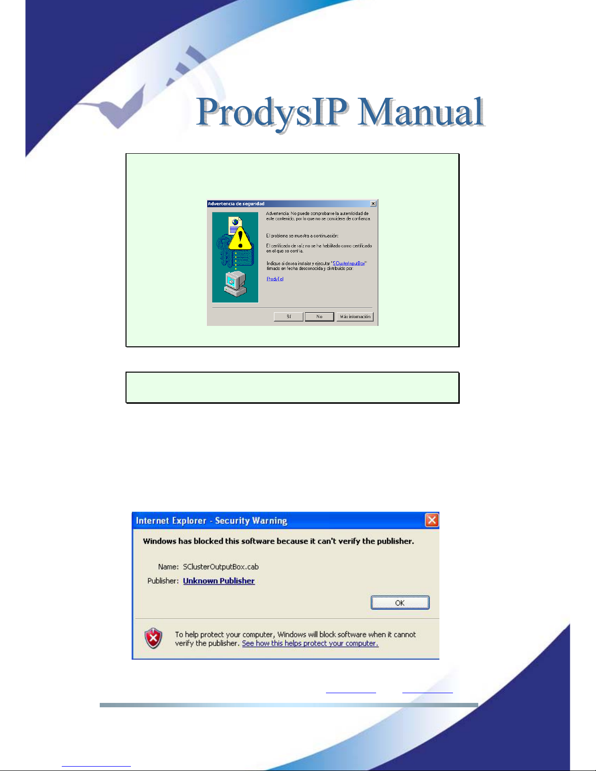
The first time the user accesses the Prodys IP Family codec web page, an OCX
file has to be downloaded and installed on the computer.
Microsoft Internet
Explorer can be configured to block OCX objects installation and/or execution.
So, depending on the configuration of the web browser, the following message
can appear when first accessing the Prodys IP Family codec web page:
Page 11
Prodys S.L. Tel: +34 91 6896880 Θ Fax: +34 91 6943777 Θ Email: [email protected] Θ Web: www.prodys.com
Page 11
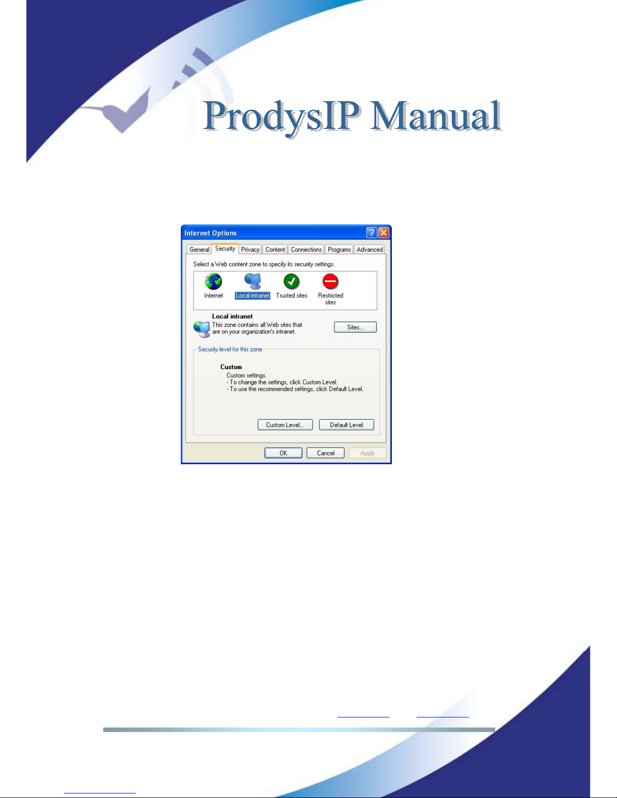
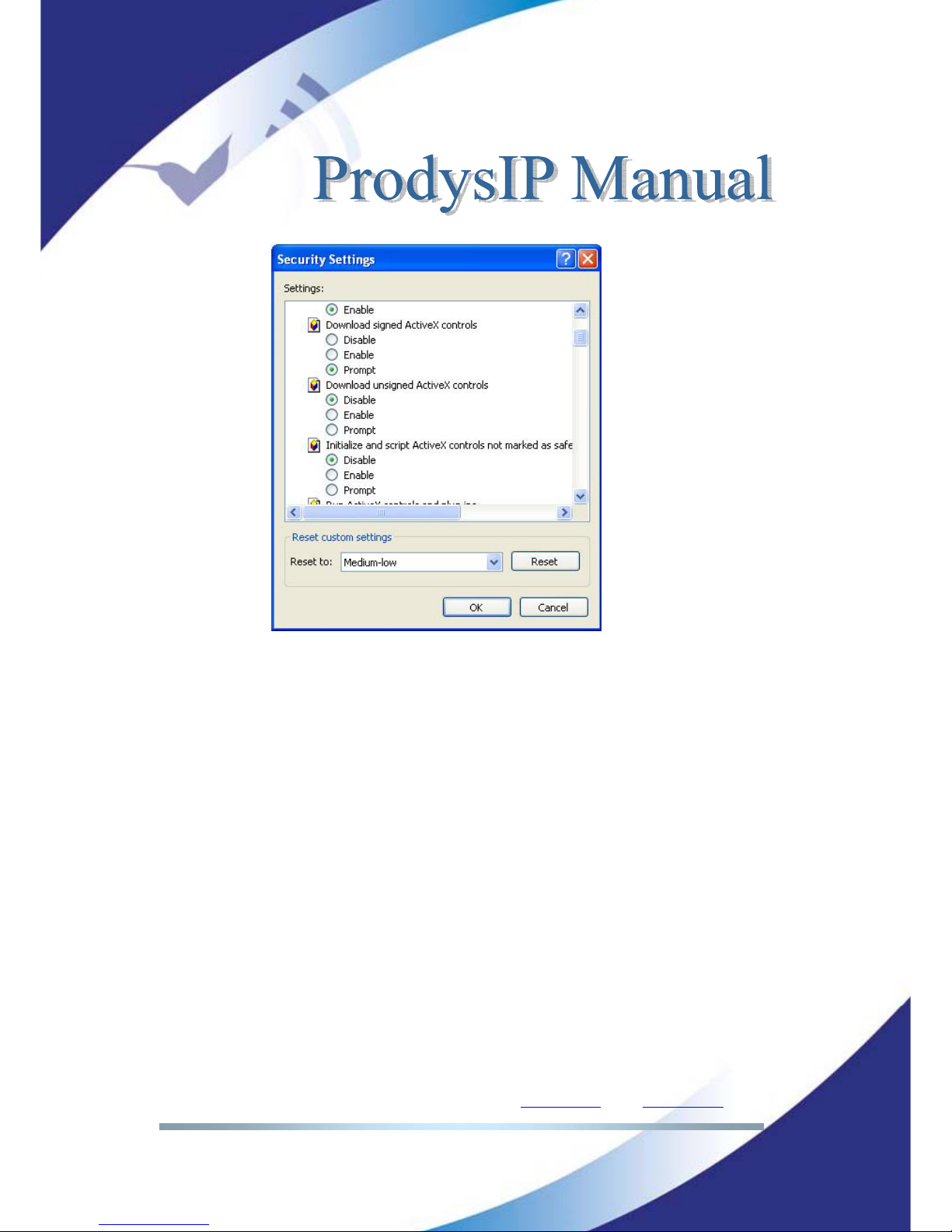
Go to Internet Options in IExplorer, click on ‘Security’ tab, and set ‘prompt’
when downloading ActiveX signed and unsigned controls at Local and
Internet zones.
Page 12
Prodys S.L. Tel: +34 91 6896880 Θ Fax: +34 91 6943777 Θ Email: [email protected] Θ Web: www.prodys.com
Page 12
Windows Vista: Should the user experience a problem when downloading the
OCX file when first accessing the web page of the unit,
please disable UAC (User
Access Control) on Windows Vista.
Once the OCX file has been installed in the
computer, UAC can be enabled again.
Each firmware version might have a different OCX file, so the new OCX should be
installed as it is done for the first access to the web page of the unit. If the unit
was upgraded and, depending on the ‘cache’ configuration of the Internet
explorer, there might be problems when accessing the web page, given that the
old web page might be offered by the browser instead of the real one, which
should be installed to replace the old one. In this case, a message indicating
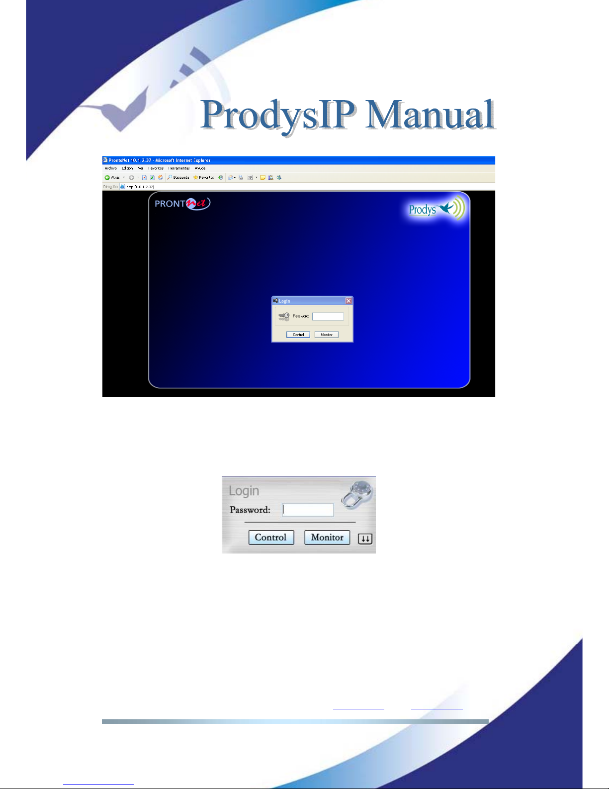
‘Incorrect Versions’ will appear as soon as the user click on ‘Control’ or ‘Monitor’
on the Prodys login page. Click on F5 to skip the cache entries, and access to the
‘real’ web page. Even after pressing F5 and, depending on the IExplrorer
configuration and/or version, this situation might continue.
In that case, go to
Internet Options in IExplorer, click on ‘General’ tab, and delete temporary files.
To access the Prodys IP Family codec from the Internet Explorer enter the IP
address of the unit in the address bar as shown here:
Page 13
Prodys S.L. Tel: +34 91 6896880 Θ Fax: +34 91 6943777 Θ Email: [email protected] Θ Web: www.prodys.com
Page 13
User can choose whether to gain the Web Browser access to the codec with
monitor or control privilege. Bear in mind that only one web browser at a time
can control the unit. However, it is possible to monitor the unit from several web
browsers simultaneously.
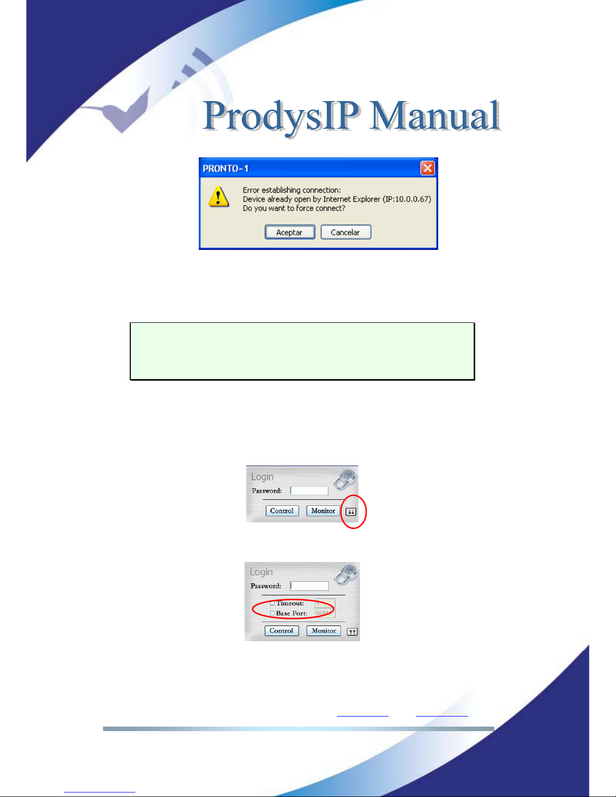
If a unit is already being controlled by a web page and we try to get the control
from another web browser, a message will appear. This message will indicate
that the unit is already being controlled from another PC and the IP address of
this computer.
Page 14
Prodys S.L. Tel: +34 91 6896880 Θ Fax: +34 91 6943777 Θ Email: [email protected] Θ Web: www.prodys.com
Page 14
It is possible to get the control by pressing OK. Then, the connection of the old
owner will be closed and the unit will be blocked for new controller.
This system is fully integrated with the ProdysControl. In that way, the
control from/to ProdysControl can be revoked. It is possible to have a unit
being controlled by ProdysControl and at the same time, web browsers
monitoring the same unit, etc…
When entering the web page, the user can set the time-out period for the
connection between the PC running the web browser and the unit. By default,
this period is set to 5 seconds. To modify this parameter, click on the advance
features button of the login window,
then define the new value from the following window:
The user should take into account that the longer the time-out, the less likely it
is that the connection between the PC and the unit will be lost.
Page 15
Prodys S.L. Tel: +34 91 6896880 Θ Fax: +34 91 6943777 Θ Email: [email protected] Θ Web: www.prodys.com
Page 15
The user control Timeout definition does not affect the audio streaming protocol
Timeout.
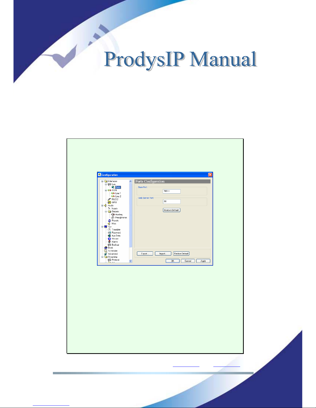
Base Port: When Prodys IP Family codec ports have been modified since the
factory default configuration, it will be necessary to indicate the new port at the
Prodys IP Family codec web browser address line. An example is given at the
end of the green remarked box.
MORE ABOUT THE PRODYS IP FAMILY CODEC PORTS
Changing Prodys IP Family codec Ports: The Prodys IP Family codec
configuration menu allows the user to configure which ports the unit will use
for its TCP/UDP/IP communications from the web page.
There are two different groups:
Web Server Port: By default, it is TCP port 80. This is the internal web server
port.
Base Port: By default, it is 50011 for TCP and UDP ports. This is the first port
of the range of ports used by the unit for management and for the audio
communications over IP with Prodys V1 and V2 protocols (Prodys V3 uses
different ports other than these ones). From this base port on, up to 32 ports
should opened/forwarded. That is, if the base port is set to 50011, the range of
ports goes from 50011 to 50041 (plus 51000 and 51001), both for UDP and
TCP. Therefore any modification of the default values should be taken into
account (e.g. opening /forwarding in the corresponding router/firewall if
required).
Page 16
Prodys S.L. Tel: +34 91 6896880 Θ Fax: +34 91 6943777 Θ Email: [email protected] Θ Web: www.prodys.com
Page 16
IMPORTANT
The following should be taken into consideration when changing the base
port:
To access the web page of the unit, the new port has to be indicated in
the http address bar of the web browser after the IP address, separated
by a colon:
http://<IP>:<Port> Example: 192.168.0.10:8080
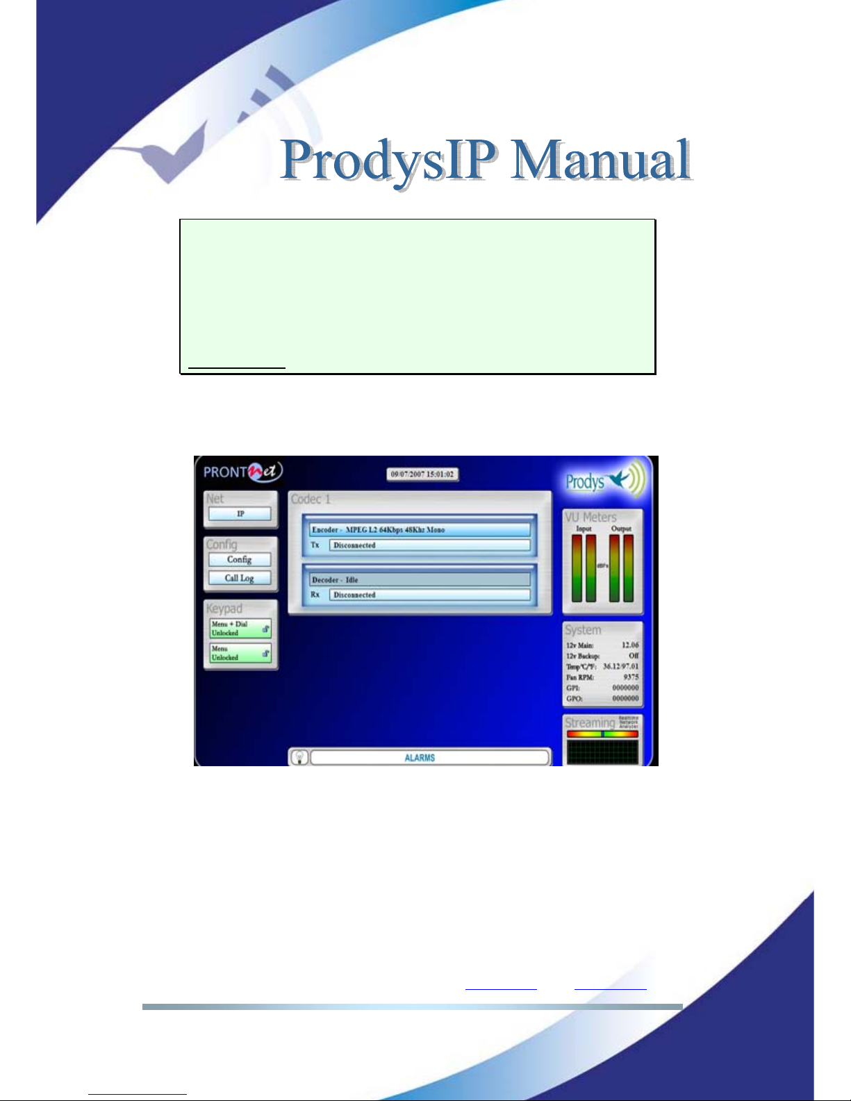
Once the page is entered correctly, the web browser will display the “Home
Page”:
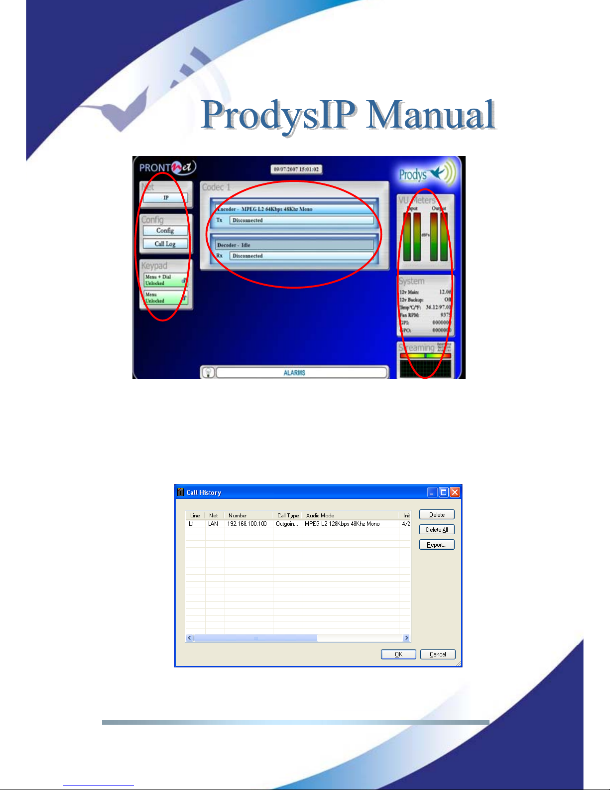
The Prodys IP Family codec Web page is arranged in three main areas:
General Configuration area.
n
Control area.
o
Monitor area.
p
Page 17
Prodys S.L. Tel: +34 91 6896880 Θ Fax: +34 91 6943777 Θ Email: [email protected] Θ Web: www.prodys.com
Page 17
By clicking on any button on the menu bar or any highlighted zone, individual
configuration pages are displayed.
Clicking on the ‘Call Log’ button brings up the Call Log: A history report has
been included to record the input and output calls according to the following
information: telephone/IP, audio modes, date and start/end time, length of each
call, etc…
n
o
p
Page 18
Prodys S.L. Tel: +34 91 6896880 Θ Fax: +34 91 6943777 Θ Email: [email protected] Θ Web: www.prodys.com
Page 18
QUICK START
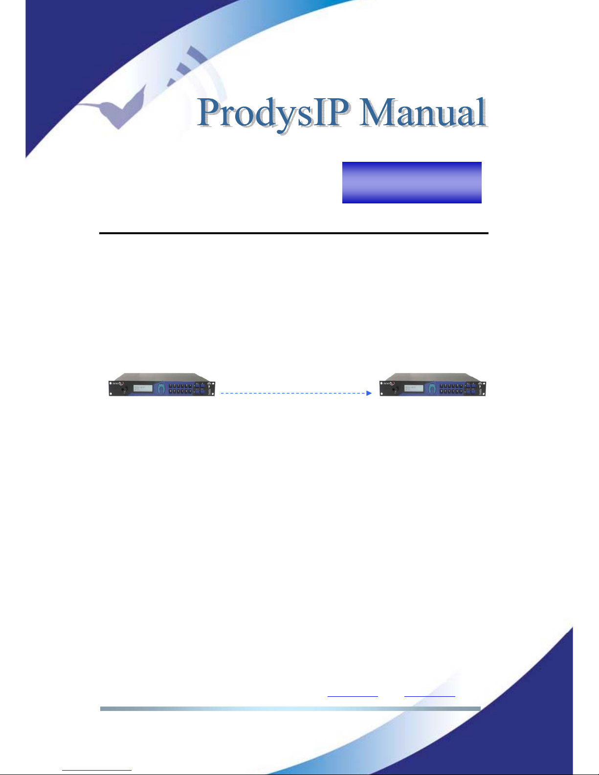
This chapter guides new user thru the basic steps to start an audio connection
over IP between two Prodys IP Family codecs.
Furthermore this example is also a good starting point for users focused on audio
connections over ISDN or X21. (Please refer to section V.7 and V.8 for a detailed
guide for those networks).
Given is:
Both codecs are connected on the same Local Area Network.
The user gains control access to the codec as detailed in chapter II.
The codecs remains with the factory default settings (but the IP address).
To recover the factory default configuration, please refer to heading of the
configuration chapter (IV).
Prodys IP codec
192.168.100.100
Prodys IP codec
192.168.100.102
Calling to 192.168.100.102
Audio streaming
Chapter III
Page 19
Prodys S.L. Tel: +34 91 6896880 Θ Fax: +34 91 6943777 Θ Email: [email protected] Θ Web: www.prodys.com
Page 19
III.1 Selection of the network interface and protocol
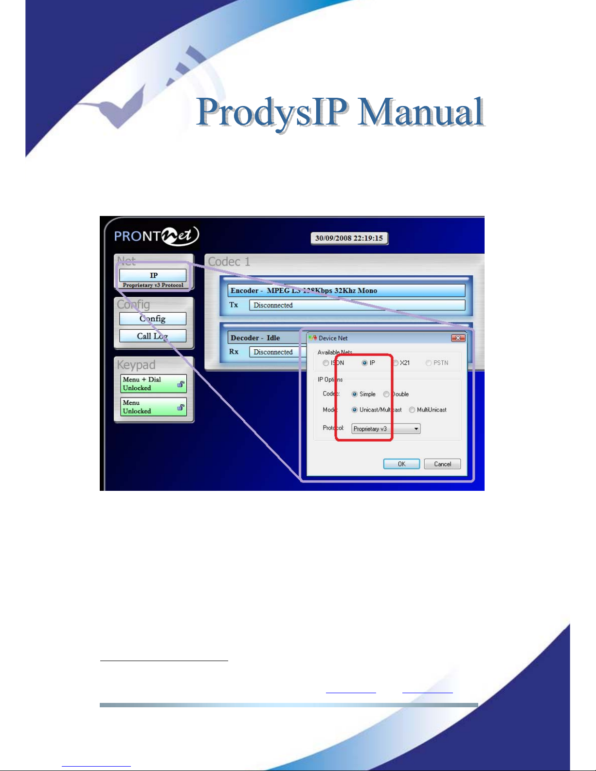
The user has to select the IP Network Interface and match the IP protocol on
both codecs. For this example we propose Proprietary Protocol V3.
5
5
Further details on section V.1
Page 20
Prodys S.L. Tel: +34 91 6896880 Θ Fax: +34 91 6943777 Θ Email: [email protected] Θ Web: www.prodys.com
Page 20
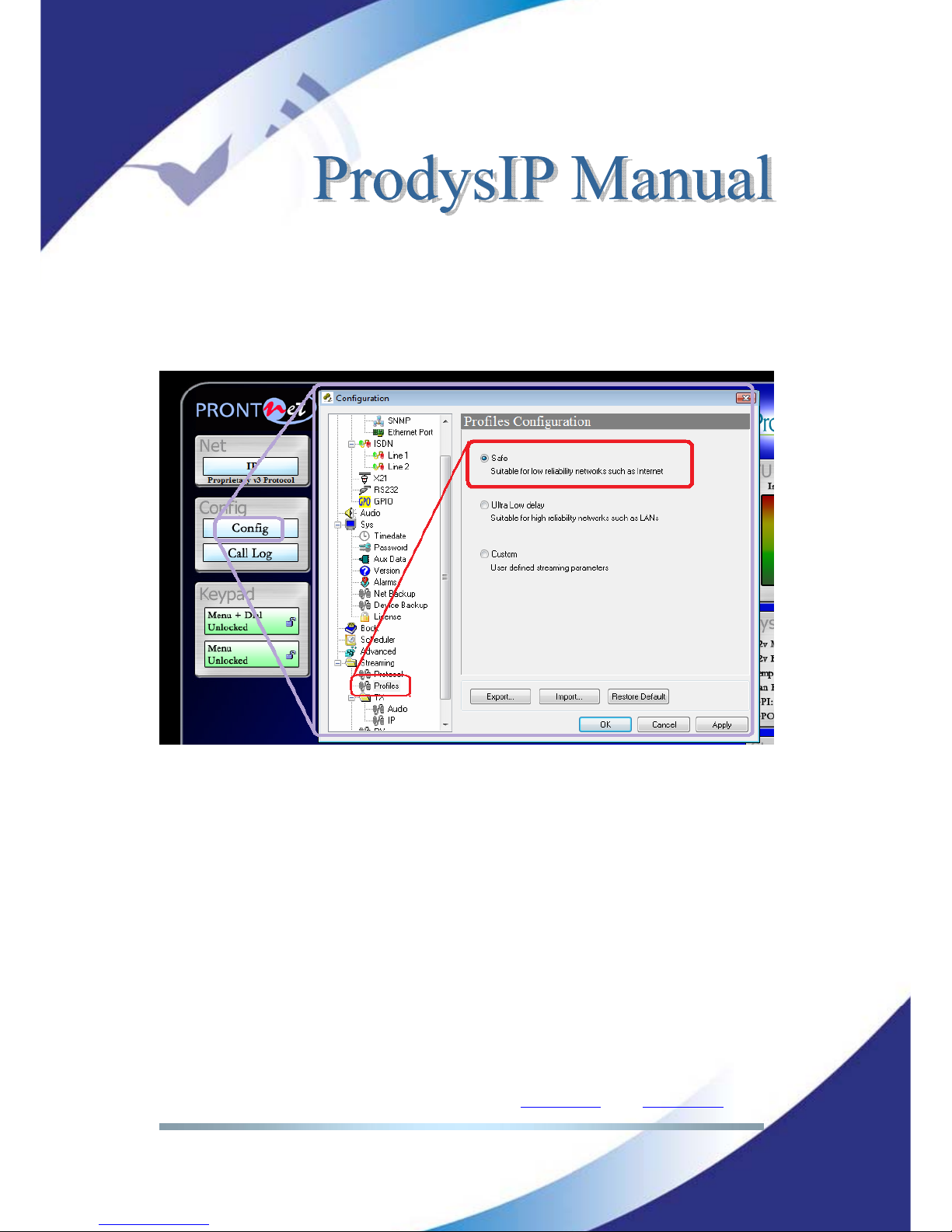
III.2 Selection of the network profile
The user might select the network profile of his choice with just a handy
shortcut.
Page 21
Prodys S.L. Tel: +34 91 6896880 Θ Fax: +34 91 6943777 Θ Email: [email protected] Θ Web: www.prodys.com
Page 21
III.3 Selection of the Encoder algorithm
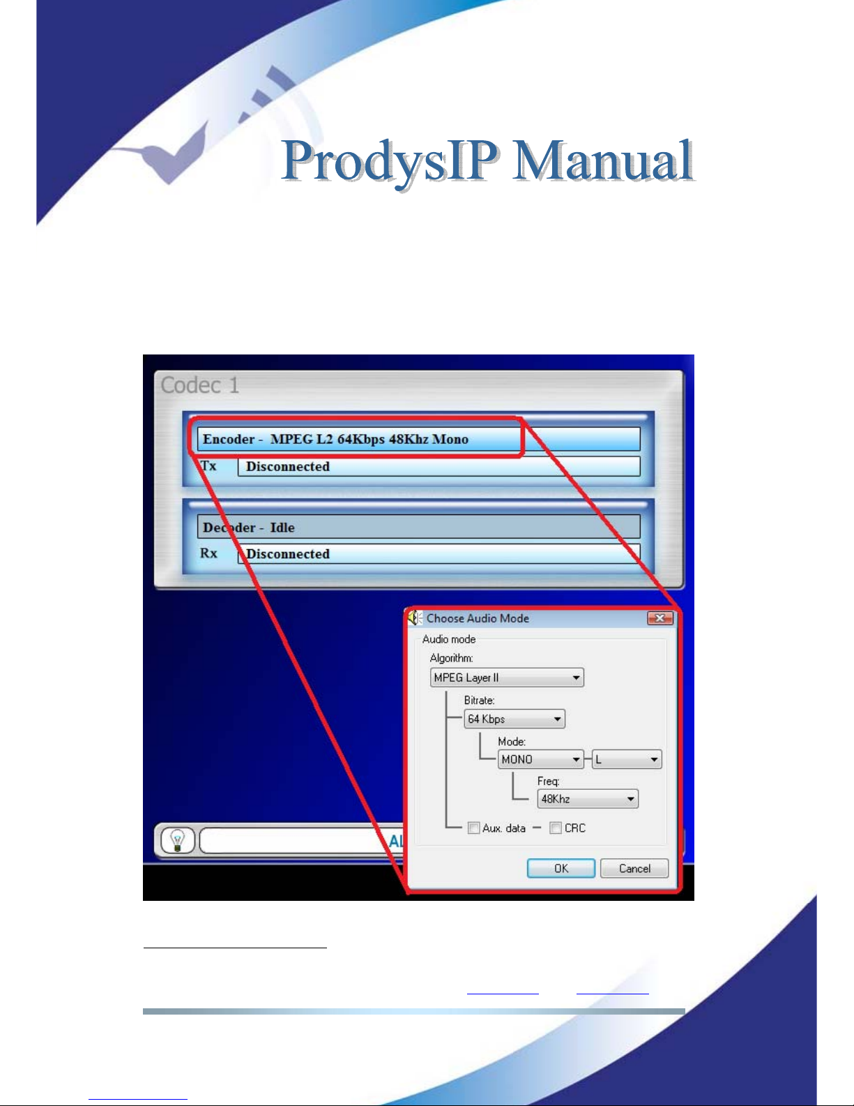
The user is required to select the Encoder compression algorithm of his fond for
both codecs in place.
It is remarked that the user is not required to define the Decoder compression
algorithm, since Prodys decoding engine is fully automated.
6
6
Further details on section V.5
Page 22
Prodys S.L. Tel: +34 91 6896880 Θ Fax: +34 91 6943777 Θ Email: [email protected] Θ Web: www.prodys.com
Page 22
III.4 Dialling the destination codec
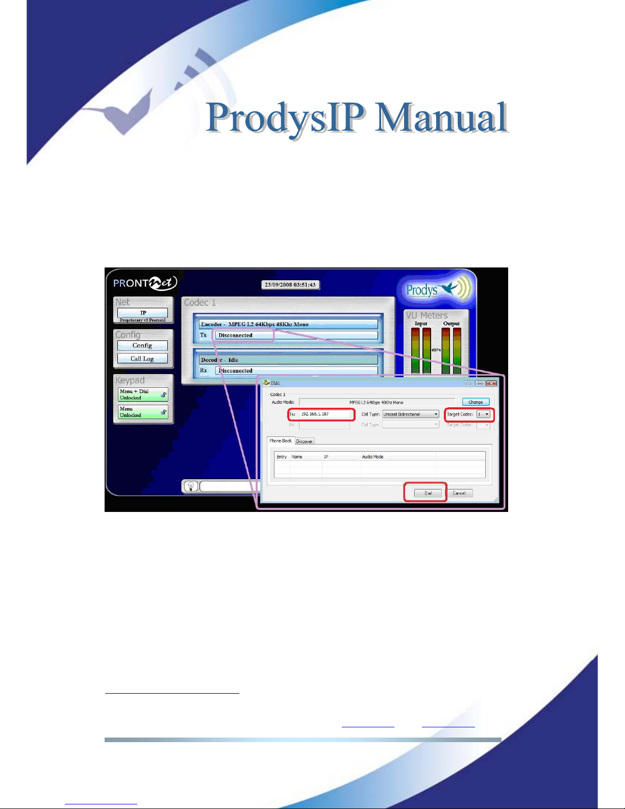
The last step is to dial the destination codec according to the figure. Parameters
to match are the IP Address of the remote codec and the codec number
7
(by
default codec 1).
Please refer also to section ¡Error! No se encuentra el origen de la
referencia. for related information.
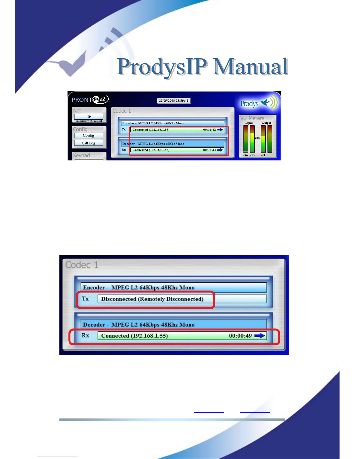
Immediately the audio streaming over IP takes place between both codecs. The
user gets feedback of the dialling success with a green connection indication.
7
Please refer to section V.4 for details on Target Codec.
Page 23
Prodys S.L. Tel: +34 91 6896880 Θ Fax: +34 91 6943777 Θ Email: [email protected] Θ Web: www.prodys.com
Page 23
III.5 Stopping a communication
The user might stop an audio stream in progress by double clicking the upper
green connection indication at any time.
III.6 Encoder and Decoder status indication
Upon the selected network interface and protocol, there are several status
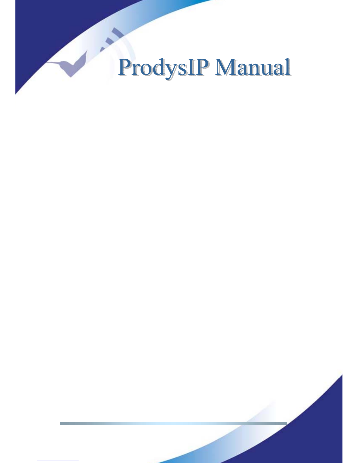
indications available for the encoder and decoder part of the codec:
<No physical Line>: The communication line is not physically detected. The
user is kindly asked to check the network interface cable.
<Connected>: The line is connected. An arrow will indicate if it is an
incoming or outgoing call.
Page 24
Prodys S.L. Tel: +34 91 6896880 Θ Fax: +34 91 6943777 Θ Email: [email protected] Θ Web: www.prodys.com
Page 24
The duration of the call also is indicated.
<Disconnected>: The line is detected physically but no audio streaming is in
progress. Beside the text appear the disconnection codes.
<Disconnected (Connection Rejected)>: The far-end codec is addressed, but
this codec can not take the call because the codec is busy or the Target
codec is not available
8
.
<Calling>: A dialling is in progress or the codec is waiting for the far-end to
complete the invitation (eg. manually answer at the far-end)
<Ring>: Receiving an in-dialling call on the line.
III.7 Decoder Status
Further information is applicable only to the Decoder status:
<Searching>: The decoder is not synchronized yet with the incoming audio
stream at the receiver. The decoder engine is searching to get in sync with
the proper compression algorithm.
<Framed>: The decoder is synchronized.
<Stopped>: Some restriction applies for the Decoder and therefore signal
will not be available at the audio outputs. (eg. the codec has not got a valid
Prodys’ license for the incoming compression algorithm, or the Decoder and
Encoder compression algorithms are incompatible on the same codec.)
8
Please refer to section V.4 for details on Target Codec.
Page 25
Prodys S.L. Tel: +34 91 6896880 Θ Fax: +34 91 6943777 Θ Email: [email protected] Θ Web: www.prodys.com
Page 25
CONFIGURATION
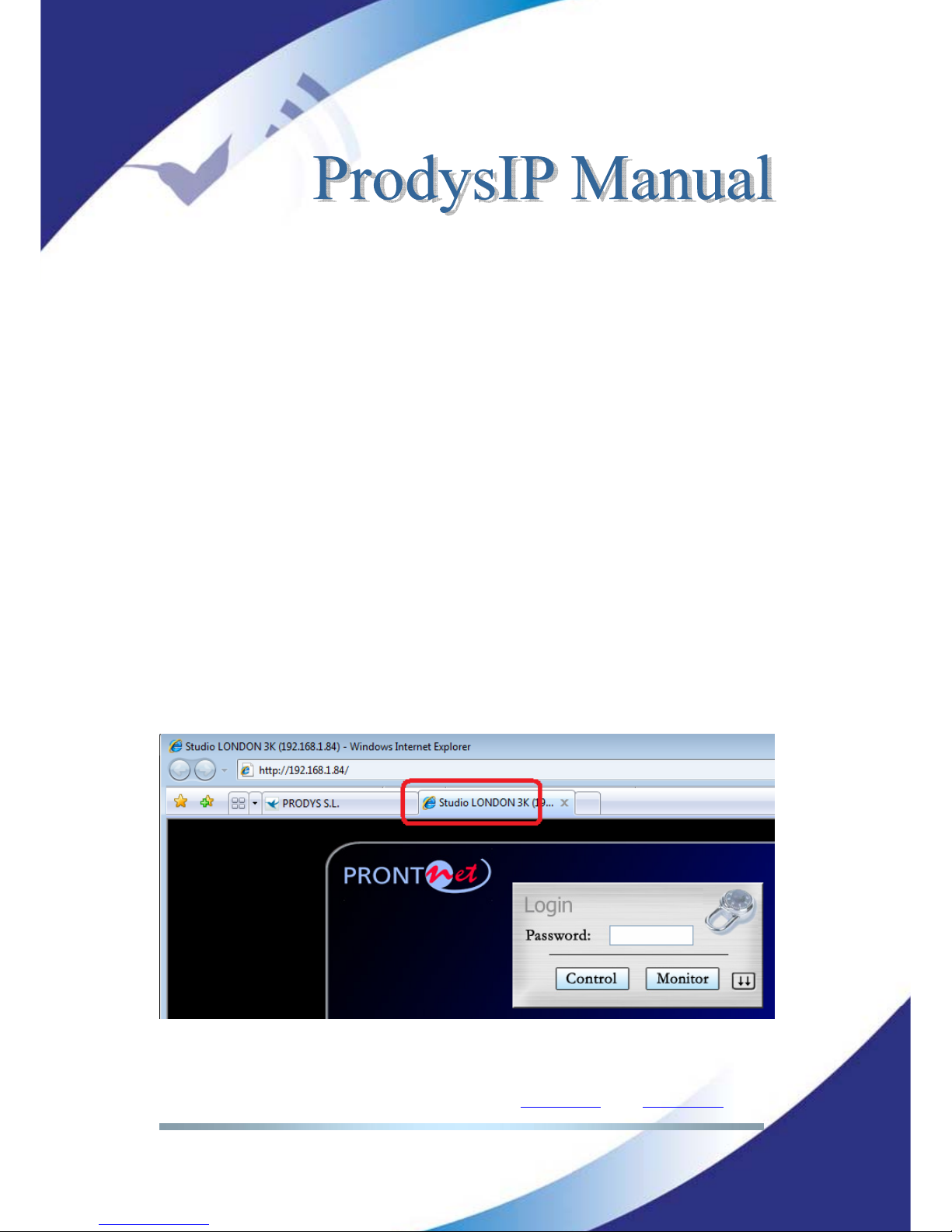
Clicking on the <Config> button from the top web browser control page brings
up the configuration page:
The factory default configuration can be restored by pressing <Restore Default>
& <OK>. This option allows the user to restore the factory default configuration,
except those parameters related to the LAN configuration: IP address, netmask
and gateway.
Chapter IV
Page 26
Prodys S.L. Tel: +34 91 6896880 Θ Fax: +34 91 6943777 Θ Email: [email protected] Θ Web: www.prodys.com
Page 26
To apply the changes, the user can press either the <OK> button or the
<Apply> button. By pressing the Apply button the changes will be applied but
the configuration window will remain.
<Export>: This option copies the complete codec configuration to the computer
disk. The user is requested to indicate the computer directory.
<Import>: It copies the complete codec configuration from the computer
directory. This imported configuration is placed in force as soon the <OK> or
<Apply> button are pressed.
IV.1 Interfaces
By clicking on the <Interfaces> menu, the port configuration dialog appears. The
ports can be selected on the left side (LAN, ISDN, X21, PSTN, RS232 or GPIO).
The right window shows the window dialog to configure the selected port. For
example, if we select the LAN interface:
IV.1.1 LAN port
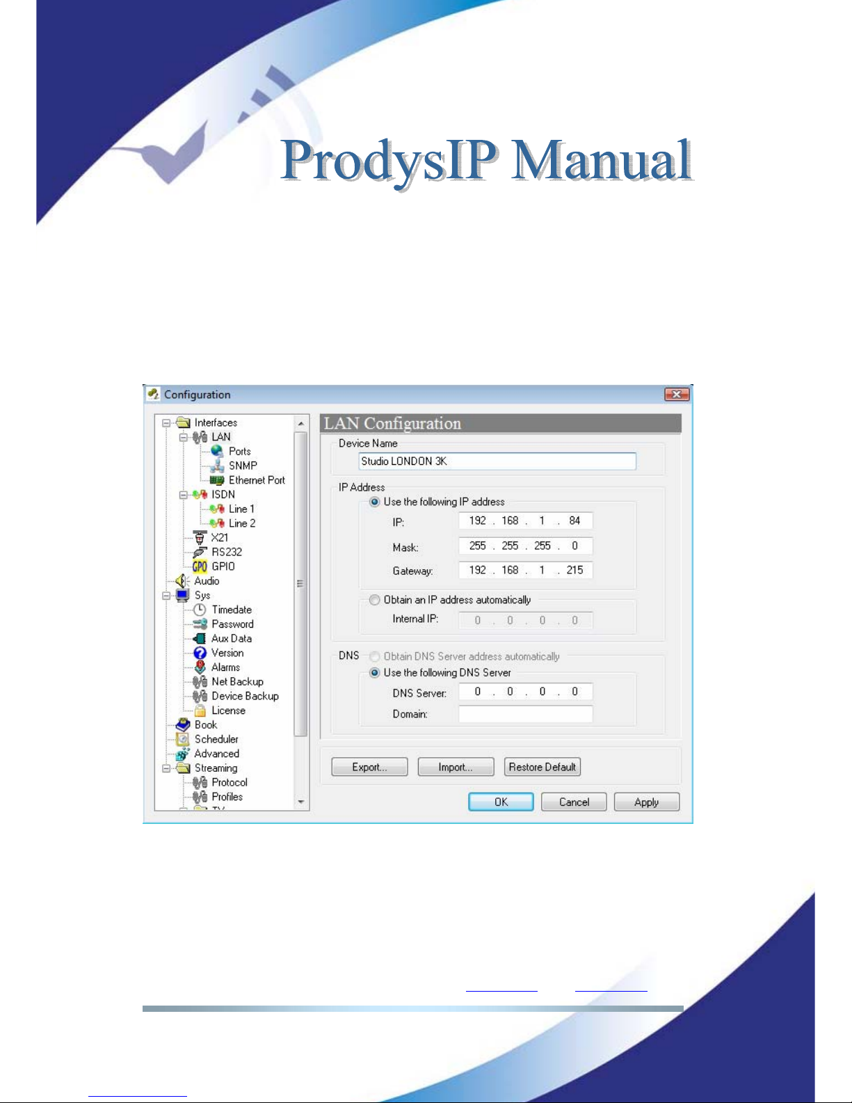
The first definition on this menu is the <Device Name>, which sets the IExplorer
tab label with a meaningful indication. This name will be also available on the
front panel display, and it will be used to send alarm email alerts when enabled.
Prodys IP Family codec allows the assigning of the IP parameters either manually
or automatically (by DHCP).
Page 27
Prodys S.L. Tel: +34 91 6896880 Θ Fax: +34 91 6943777 Θ Email: [email protected] Θ Web: www.prodys.com
Page 27
Manually Æ User must enter the following IP parameters manually:
<IP address>
<Mask>
<Gateway IP address>
Automatically Æ Check “Obtain an IP address automatically” option to get the
configuration automatically from a DHCP Server.
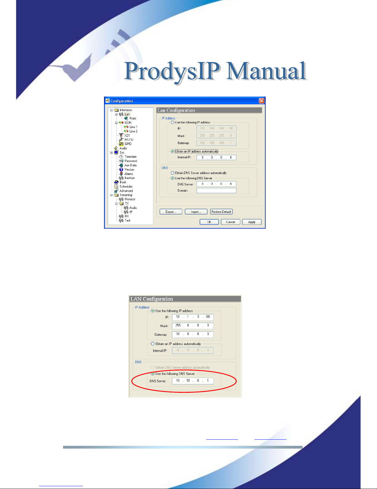
By setting DHCP, the codec will get its IP parameters when starting up. This IP
setting might be different from time to time, that is why Prodys IP Family codec
supports RIP2 protocol. This protocol allows the user to set an ‘internal’ IP
address, in order that the unit can be identified regardless of the IP settings
provided by the DHCP server.
Page 28
Prodys S.L. Tel: +34 91 6896880 Θ Fax: +34 91 6943777 Θ Email: [email protected] Θ Web: www.prodys.com
Page 28
• DNS support:
By specifying the IP address of a DNS Server, the user can make calls to
‘names’ instead of IP addresses
. This new feature is available in any place
where an IP address has to be entered. For example: the dial window, the
phone book, SNTP IP server address…This is the DNS configuration windows:
As can be seen from the picture, the DNS information can be obtained
from a DHCP Server.
Page 29
Prodys S.L. Tel: +34 91 6896880 Θ Fax: +34 91 6943777 Θ Email: [email protected] Θ Web: www.prodys.com
Page 29
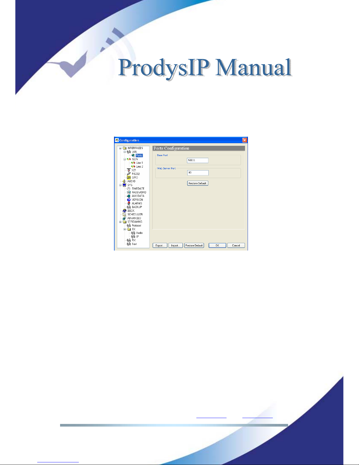
IV.1.2 Ports
It is possible to configure which ports the unit will use when selecting Prodys
proprietary protocols for IP communications.
There are two different groups:
<Web Server Port>: By default, it is TCP port 80. This is the internal web
server port.
<Base Port>: By default, it is 50011 for TCP and UDP ports. This is the
first port of the range of ports used by Prodys Proprietary Protocols V1 &
V2, along with the management ports. From this base port, up to 30 ports
should be opened/forwarded. That is, if the base port is set to 50011, the
range of ports goes from 50011 to 50041, both for UDP and TCP, should
be opened/forwarded in the corresponding router/firewall (when
required), in order for the audio and management traffic is routed
appropriately to the ProntoNet. This is the simplest way to deal with the
port configuration of routers/firewalls. In case only the management ports
have to be opened a more detailed list of ports and different configuration
examples are provided in chapter V.6.4 More about Prodys Proprietary
Protocols.
Page 30

Prodys S.L. Tel: +34 91 6896880 Θ Fax: +34 91 6943777 Θ Email: [email protected] Θ Web: www.prodys.com
Page 30
The following things should be taken into consideration when changing the base
port:
1. To access the web page of the unit, the new port has to be indicated in
the http address bar of the web browser after the IP address, separated
by a colon:
http://<IP>:<Port
> Example: 192.168.0.10:8080
To log into the unit, click on the advance features button of the login
window:
and specify the base port which we want to connect to:
When establishing a call, the new base port must be entered after the IP
address, separated by a colon. Example: When calling to a unit which IP address
is 192.168.1.2, and base port 40011, the following call destination should be
entered into the ‘Dial’ window: 192.168.1.2:40011.
When establishing a bidirectional call with Prodys IP codecs using Prodys
Proprietary Protocols V1 or V2, two connections are made automatically, one for
each direction. For the receiver to call properly to the caller (
only in case the
base port in the caller is not the default one
), it should have an entry on its
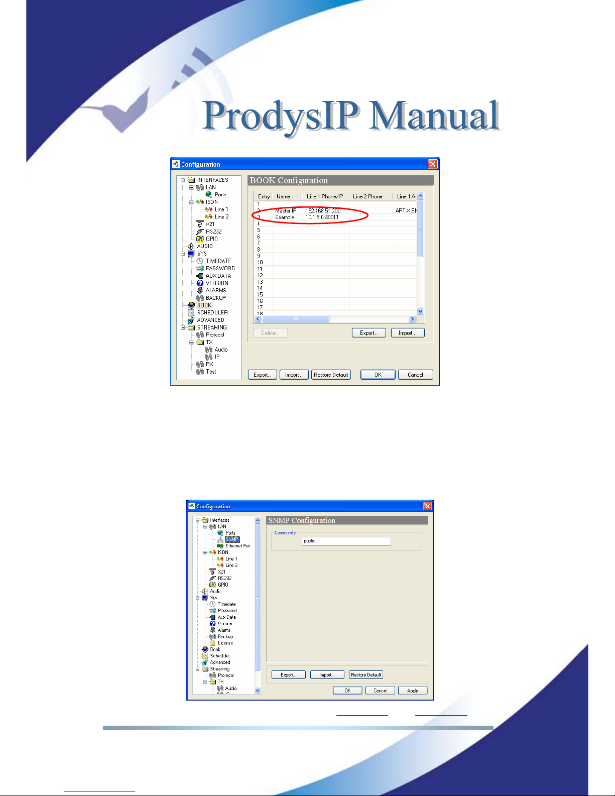
phone book with the IP address of the caller and the base port of the caller.
Example: if the caller has the IP address 10.1.5.0 and its base port is 40011, in
the receiver, the following entry should be configured in its phone book:
Page 31
Prodys S.L. Tel: +34 91 6896880 Θ Fax: +34 91 6943777 Θ Email: [email protected] Θ Web: www.prodys.com
Page 31
NOTE: Take into account that this is not necessary when working with
Prodys Proprietary version 3 protocol.
IV.1.3 SNMP configuration
It is possible to set the SNMP community.
Page 32
Prodys S.L. Tel: +34 91 6896880 Θ Fax: +34 91 6943777 Θ Email: [email protected] Θ Web: www.prodys.com
Page 32
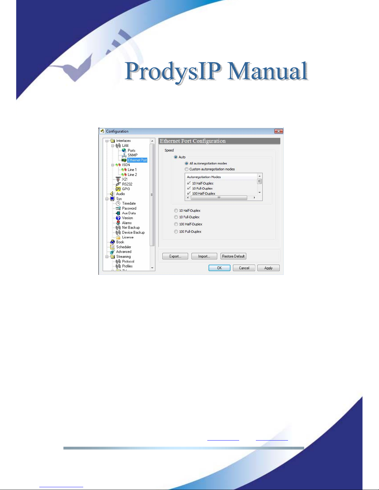
IV.1.4 Ethernet Port Configuration
It is possible to set speed and duplex configuration to the following values:
NOTE: When the unit is connected to a device which does not support autonegotiation, and it is set to work in a fixed mode, the Ethernet interface must be
configured to match the configuration of that device, so ‘Auto’ should not be
selected in this case.
Page 33
Prodys S.L. Tel: +34 91 6896880 Θ Fax: +34 91 6943777 Θ Email: [email protected] Θ Web: www.prodys.com
Page 33
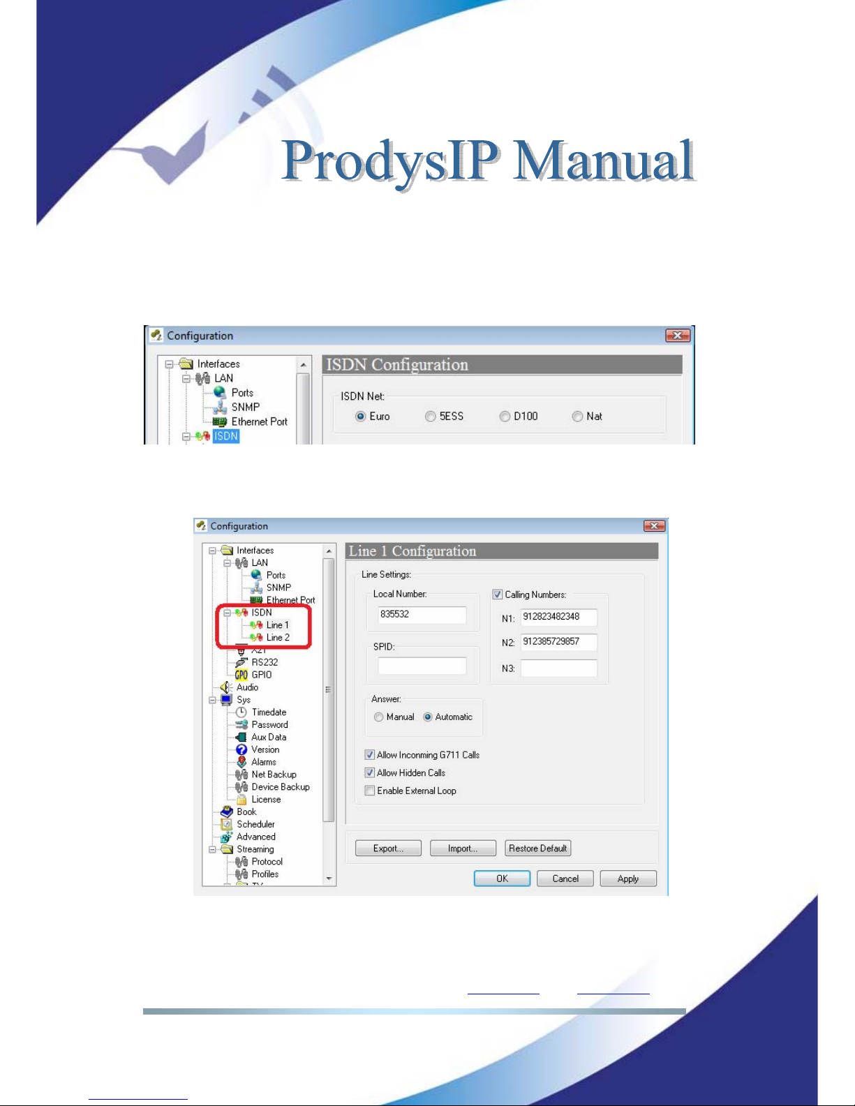
IV.1.5 ISDN Terminal Adaptor configuration
The first dialog allows the selection of the ISDN protocol according to the
national network in place. There are four options:
Euro-ISDN, 5ESS, DMS 100 and NAT1:
The options Line 1 and Line 2 allows the user to configure in each line (B
channel) the Local Number, Calling number filters and the answering mode:
<Automatic> or <manual> answer: Incoming calls can be answered
automatically or manually upon this option. If the mode is set to manual,
Page 34
Prodys S.L. Tel: +34 91 6896880 Θ Fax: +34 91 6943777 Θ Email: [email protected] Θ Web: www.prodys.com
Page 34
the red-blinking <Connection> bar must be pressed to accept the call and
connect to it.
<Calling Number>: It is possible to define up to three numbers for each
line which performs as an in-dialling filter. This is, the line will only
connect to calls with these caller IDs.
<Local Number>: It is also possible to assign a single number to each line
in such a way that the line will only respond to calls made to this local
number. This can be used if you need to map an ISDN directory number
to a specific audio port.
<Allow incoming G711 calls>: the ISDN indicates calls on G711 as voice
mode. The Prodys IP Family codec recognises this type of incoming call
and proceeds automatically to reconfigure the Encoder and Decoder to
this mode. As such, the user need not configure anything to allow the
automatic reception of incoming calls using G711.
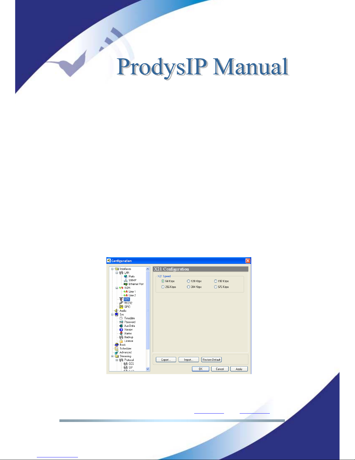
IV.1.6 X21 Port:
From this option the speed of the X21 port is selected.
Page 35
Prodys S.L. Tel: +34 91 6896880 Θ Fax: +34 91 6943777 Θ Email: [email protected] Θ Web: www.prodys.com
Page 35
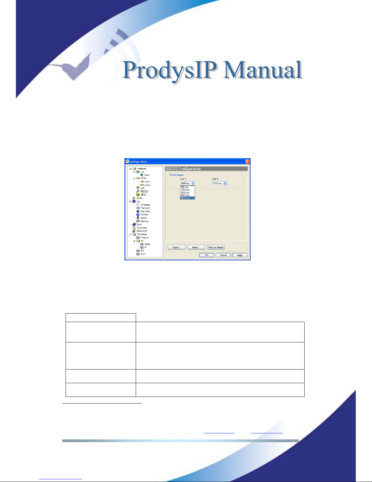
IV.1.7 RS232 Ports
There might be up two RS232 ports for use as auxiliary data ports, depending of
the model. These ports allow the transmission and reception of data along with
encoded audio. The port configuration will be always set to 8 DATA bits, NO
parity, 1 START bit and 1 STOP bit. The bit rate can be adjusted to between 300
and 9600 bps via software.
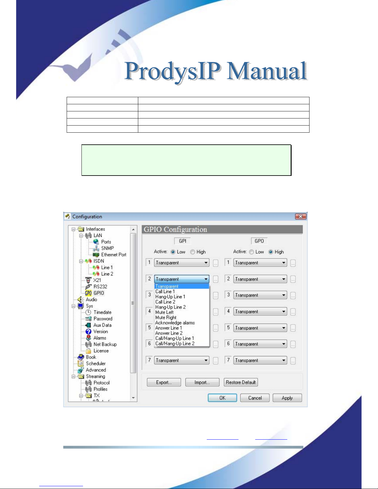
IV.1.8 GPIO Port
From this menu the GPIO port is configured. The amount of GPIO available
might be different for the specific Prodys IP Family codec, although the GPIO
definition for operation remains in any case.
INPUTS
Transparent Under this configuration, the state of the input will be present in
its homologous output in the Prodys IP Family codec connected on
the other end.
Connect From Book When this input is activated, the Prodys IP Family codec will
proceed automatically to connect the line 1 or line 2 (as
configured). The user can select which entry of the book will be
used for this purpose
9
.
Disconnect Line 1 When this input is activated, the Prodys IP Family codec will
proceed automatically to disconnect the line 1.
Disconnect Line 2 When this input is activated, the Prodys IP Family codec will
proceed automatically to disconnect the line 2.
9
Before version 5.0.0, only entries 1 and 2 of the phone book were used for calling line 1 and line
2.
Page 36
Prodys S.L. Tel: +34 91 6896880 Θ Fax: +34 91 6943777 Θ Email: [email protected] Θ Web: www.prodys.com
Page 36
Mute Left When this input is activated, the left audio output will be muted.
Mute Right When this input is activated, the right audio output will be muted.
Acknowledge alarms When this input is activated, the alarms will be acknowledged.
Answer Line1 Line 1 will be picked up when receiving a call.
Answer Line2 Line 2 will be picked up when receiving a call.
The inputs are activated by grounding.
Transparent configuration only works with audio algorithms that support ancillary
data and have been previously activated.
For electrical in/out ratings and examples of application please refer to the
“Hardware and Reference Manual” of the codec.
Page 37
Prodys S.L. Tel: +34 91 6896880 Θ Fax: +34 91 6943777 Θ Email: [email protected] Θ Web: www.prodys.com
Page 37
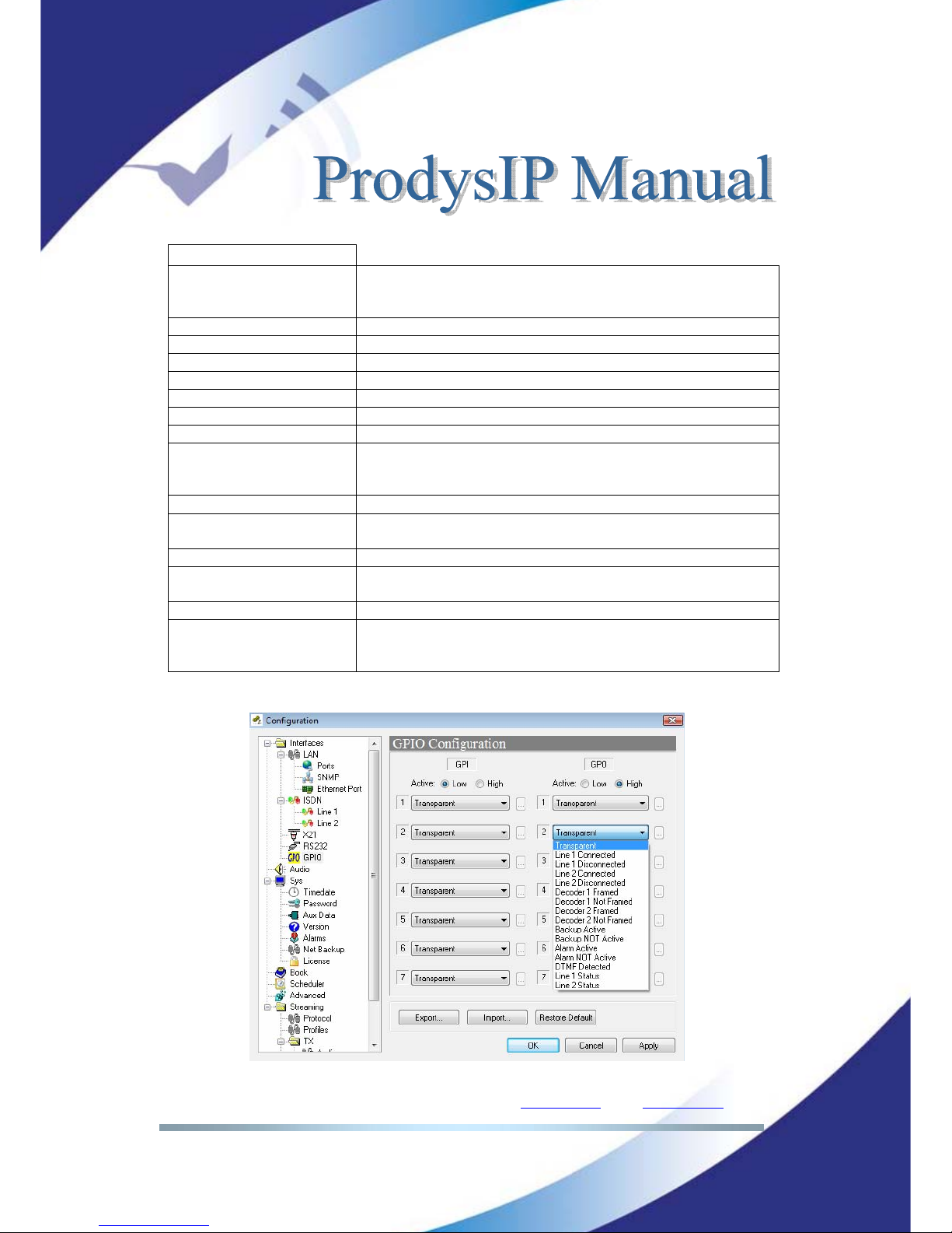
OUTPUTS
Transparent Under this configuration, the state of the output will be the same
as the corresponding input of the Prodys IP Family codec
connected on the other end.
Line 1 Connected The output will be activated when the line 1 is connected.
Line 1 Disconnected The output will be activated when the line 1 is disconnected.
Line 2 Connected The output will be activated when the line 2 is connected
Line 2 Disconnected The output will be activated when the line 2 is disconnected
Decoder 1 Framed The output will be activated when the Decoder 1 is Framed.
Decoder 1 NOT framed The output will be activated when the Decoder 1 is NOT Framed.
Decoder 2 Framed The output will be activated when the Decoder 2 is Framed.
Decoder 2 NOT framed The output will be activated when the Decoder 2 is NOT Framed.
It is only useful when the Prodys IP Family codec is working in
ISDN mode as a DUAL CODEC.
Backup Active The output will be activated when the ISDN Backup is working.
Backup NOT Active The output will be activated when the ISDN Backup is NOT
working.
Alarm Active The output will be activated when one Alarm is activated.
Alarm NOT Active
T
he output will be activated when there are NOT Alarms
activated.
DTMF detected DTMF is detected by the Decoder.
Line 1/2 Status Line Disconnected: GPO set to ‘0’.
Line Connected: GPO set to ‘1’.
Trying/receiving a call: GPO blinking (1 second period).
Page 38
Prodys S.L. Tel: +34 91 6896880 Θ Fax: +34 91 6943777 Θ Email: [email protected] Θ Web: www.prodys.com
Page 38
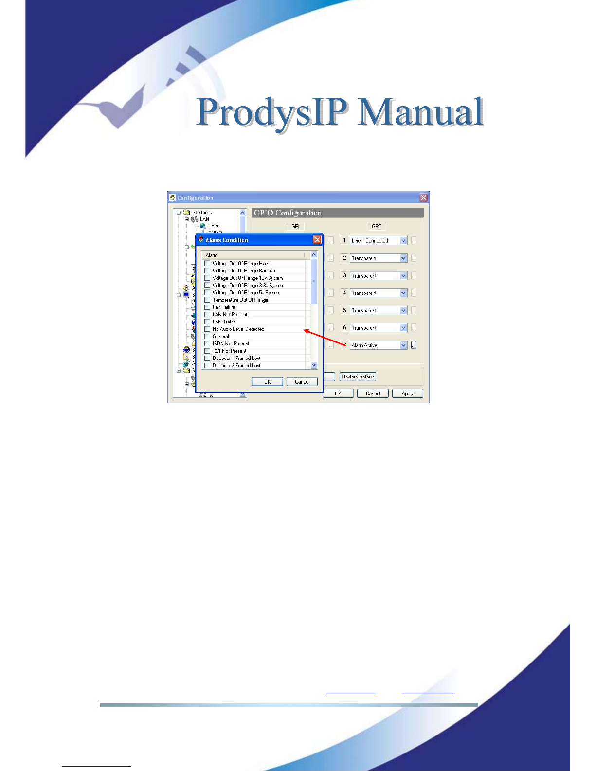
When a GPO is configured to monitor alarms <Alarm active>, it is possible to
select which alarms will enable this output.
Temperature out of range alarm will arise when the temperature goes over 50ºC.
Lan traffic alarm will come up when more than 90% of the LAN bandwidth is in
use.
This GPO will be activated when one or more of the selected alarms arise.
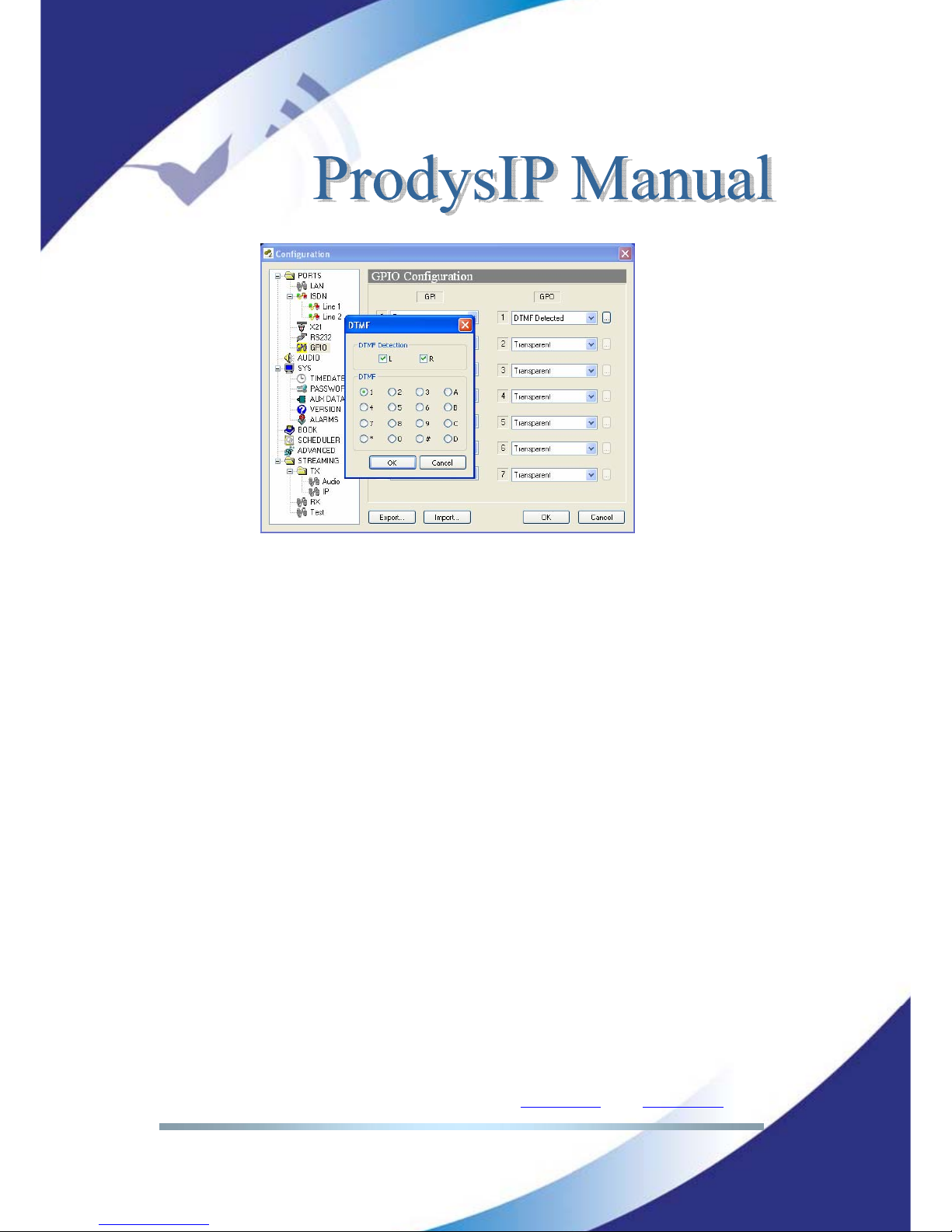
In addition, it is possible to program a GPO to be enabled when a DTMF is
detected in either Decoder. The decoder number and the DTMF which will enable
the GPO must be defined by the user.
Page 39
Prodys S.L. Tel: +34 91 6896880 Θ Fax: +34 91 6943777 Θ Email: [email protected] Θ Web: www.prodys.com
Page 39
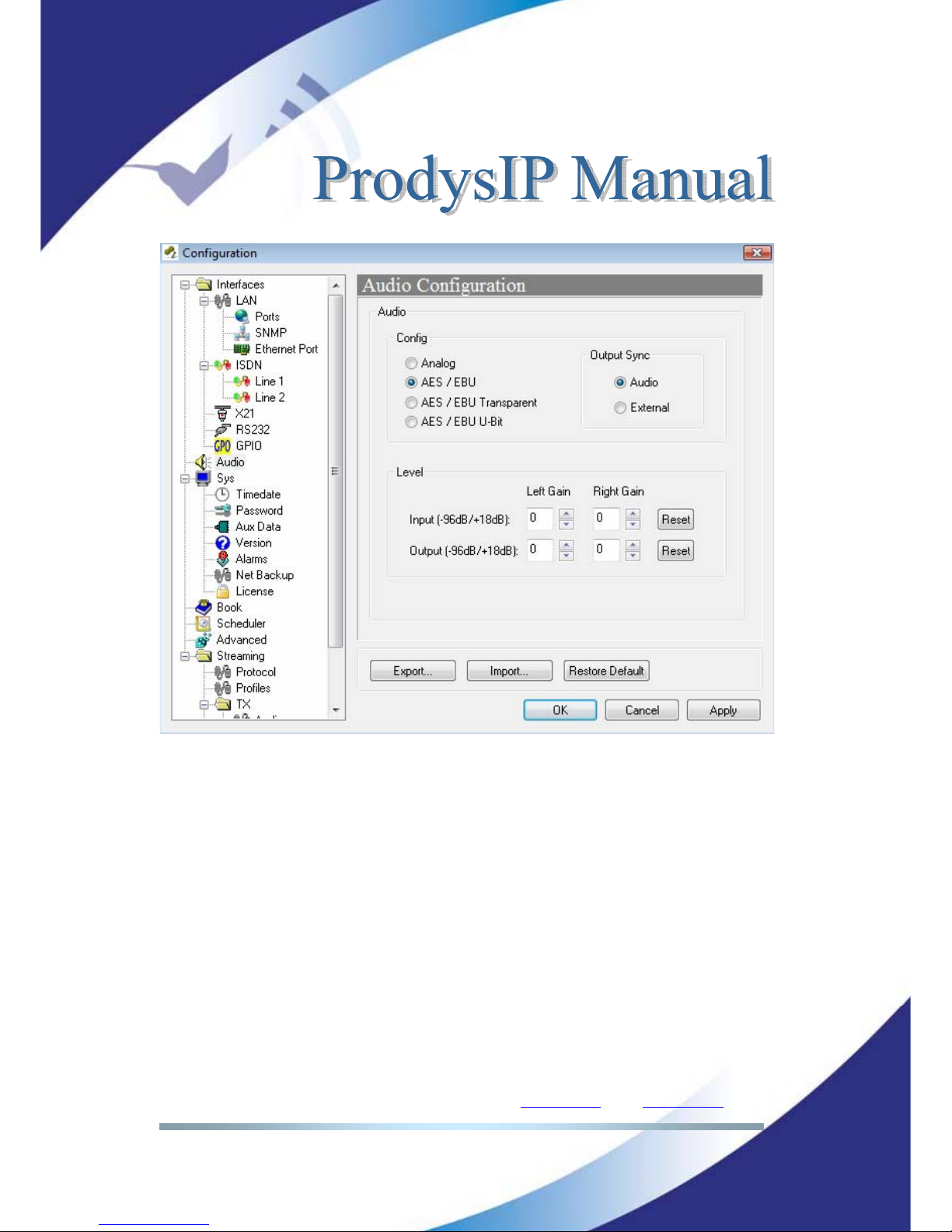
IV.1.9 Audio Configuration
<Analog> or <AES/EBU> (digital audio) input is selected at this menu. The
digital input mode provides several choices:
The <AES/EBU> which just takes and supplies the audio information from /to
the AES/EBU digital frame.
The <AES/EBU Transparent> is a special input/output mode which sets also the
network transmission mode to <PCM 24 bits> avoiding any audio payload
processing at all by the codec. This mode allows the exchange of non linear
audio at the input (or data over the AES3 interface) between codecs (e.g.
transmission of Dolby E streams).
Audio gain adjustment: Audio inputs and outputs can be adjusted digitally. Each
audio channel can be adjusted independently.
Page 40
Prodys S.L. Tel: +34 91 6896880 Θ Fax: +34 91 6943777 Θ Email: [email protected] Θ Web: www.prodys.com
Page 40
The <AES/EBU U bit> option allows the user to route also the User Bit data from
the AES/EBU frame along with the audio stream over IP. This can be useful to
control remotely some third party devices sensitive to the User Bit of the
AES/EBU frame.
Since the decoded audio will be always available on both output interfaces
(analog and digital), several syncs could be applicable for the digital stream over
the AES3 interface. Syncs could be:
<External>, which means the AES3 derives its sync from [sync input] of the
digital audio interface. As opposed, if
<External> is not selected with option
<Analog>, the internal AES3 clock is enabled.
<Audio>, which means
the AES3 derives its sync from the [AES/EBU
input] of the digital audio interface.
Page 41
Prodys S.L. Tel: +34 91 6896880 Θ Fax: +34 91 6943777 Θ Email: [email protected] Θ Web: www.prodys.com
Page 41
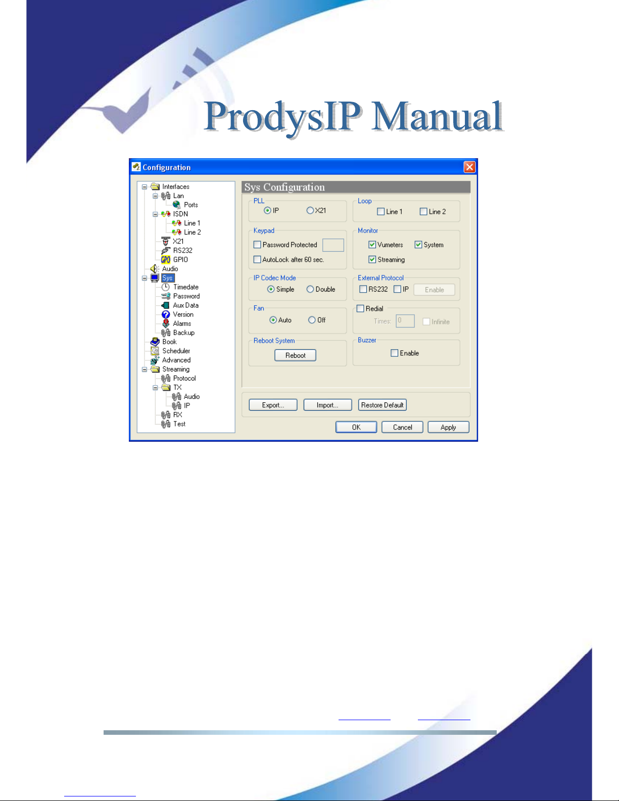
IV.2 System Configuration
Grouped here are functions that affect the general operation of the unit.
<Loop>: This sets up an Encoder-Decoder loop. Its purpose is to help the
user to check audio connections before streaming. The loop takes place in
accordance with the encoder configuration in place at that moment.
<PLL>: This is a special option that allows you to select the PLL reference
clock when NET = IP.
<Redial>: It is possible to configure a number of redials for attempting the
first call of this communication. The Prodys IP Family codec will try the
connection in the following cases:
1.- The unit is trying the connection for the first time.
2.- The unit was connected and lost the connection because the line
dropped or the line was disconnected from the other end.
<Keypad>: This option allows the user to lock automatically the frontal panel
keypad.
<Monitor>: This option allows the user to hide or display additional
information on the main window:
- VU meters: Indicates audio levels.
- System: Monitor voltages, temperatures, and fan operation.
- Streaming: Shows clock-sync algorithm operation and Buffer
Occupation Graph (Real Time Network Analyzer). This algorithm
comes into scene when receiving audio over IP. This display is
active when the audio data is "framed" - Under normal
circumstances the indicator should be in the middle Green area.
Page 42
Prodys S.L. Tel: +34 91 6896880 Θ Fax: +34 91 6943777 Θ Email: [email protected] Θ Web: www.prodys.com
Page 42
<Reboot System>: Restarts completely the codec with last configuration.
This option could play as a hardware reset for codecs placed remotely.
<External Protocol>: The Prodys IP Family codec Software Development Kit
provides a tool to manage the Prodys IP Family codec units from external
applications or devices different than ProdysControl. In this way, it is possible
to customize the control of the codecs and integrate them in a global
management system.
Please refer to the Prodys IP Family codec SDK User’s Manual.
<IP Codec Mode>: There are two different operation modes: SIMPLE and
DOUBLE mode. In SIMPLE mode, the unit will work as usual, that means, it
cannot establish two independent communications via IP. In DOUBLE mode,
the unit can establish two independent communications via IP.
In DOUBLE mode over IP, the following restrictions will be applied:
Page 43
Prodys S.L. Tel: +34 91 6896880 Θ Fax: +34 91 6943777 Θ Email: [email protected] Θ Web: www.prodys.com
Page 43
a) Only mono signals can be encoded and decoded.
b) PCM and AAC HE streaming is not supported.
c) Apt-X and enhanced Apt-X are supported only at 16kHz
sampling frequency
<Buzzer>: It is possible to enable/disable the buzzer from this option. The
buzzer warns the user about incoming calls when the unit is configured as an
ISDN, IP and PSTN codec and the answer mode is set to manual.
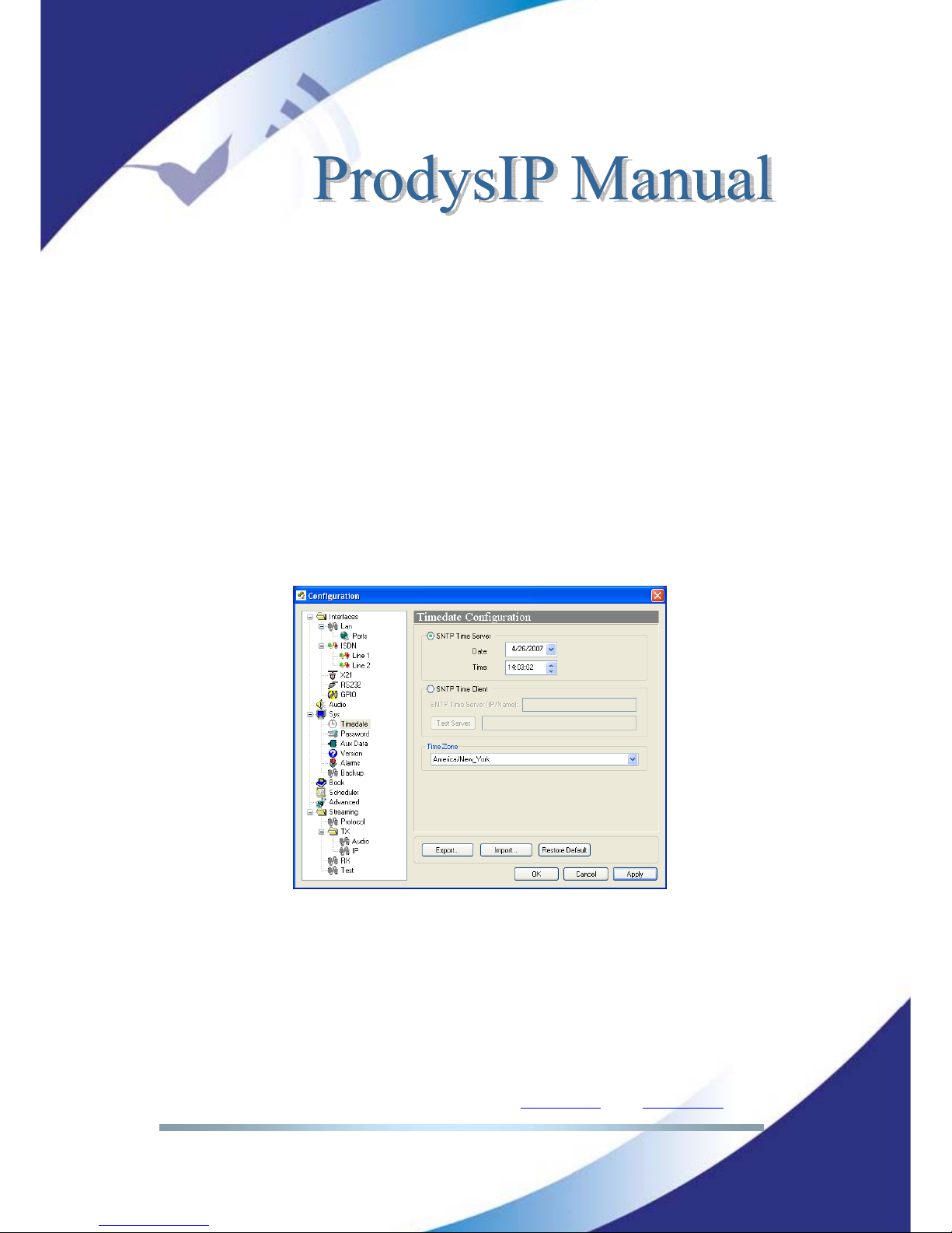
IV.2.1 TimeDate
This option allows to synchronize time and date by using SNTP protocol (Simple
Network Time Protocol). SNTP operates always in the client-server model and for
this reason Prodys IP Family codec can work as SNTP server or SNTP client.
Page 44
Prodys S.L. Tel: +34 91 6896880 Θ Fax: +34 91 6943777 Θ Email: [email protected] Θ Web: www.prodys.com
Page 44
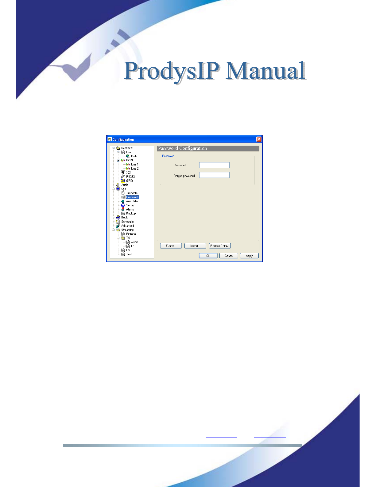
IV.2.2 Password
Whenever the web browser is started, it is necessary to enter a security
password. This is the dialog to program it.
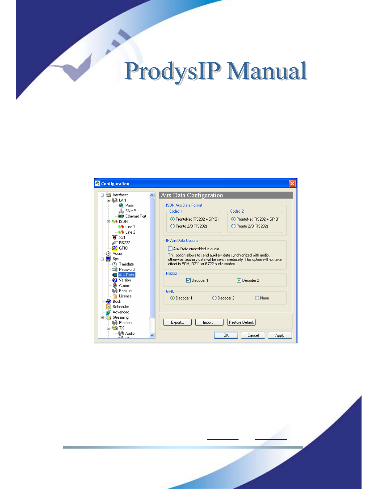
IV.2.3 Aux Data
RS232: There can be up to two RS232 ports for use as auxiliary data ports.
These ports allow the transmission and reception of data along with the
encoded audio. Port A is always ready. Port B is only available in some
codecs of the Prodys IP Family when the codec is configured as a DUAL
Codec, therefore able to operate two totally independent communication
channels. When one option is checked, the corresponding decoder will allow
the reception of ancillary data.
Over ISDN, it is possible to choose between Prodys IP Family codec format
and Pronto2/3 format (in which the GPIOs information cannot be sent). To be
backward compatible with ISDN Pronto2/3 Prodys devices, select Pronto2/3
format.
When selecting IP as communication interface, the auxiliary data can be sent
via a different path, different from the audio one (Aux. data embedded in
audio). This method has 3 big advantages: less delay independent from the
Page 45
Prodys S.L. Tel: +34 91 6896880 Θ Fax: +34 91 6943777 Θ Email: [email protected] Θ Web: www.prodys.com
Page 45
audio codification delay; the possibility to send/receive auxiliary data
regardless of the compression mode used for the audio communication; and
the possibility to send/receive the User bit of the AES/EBU frame. The
drawback is that the audio and data delay won’t be the same.
GPO: Under ‘transparent’ configuration, the state of the input will be present
in its homologous output in the Prodys IP Family codec connected at the
other end. Since there is only one GPO connector, user must select whether
to select GPO information coming from Decoder1 or from Decoder2, or none.
Page 46
Prodys S.L. Tel: +34 91 6896880 Θ Fax: +34 91 6943777 Θ Email: [email protected] Θ Web: www.prodys.com
Page 46
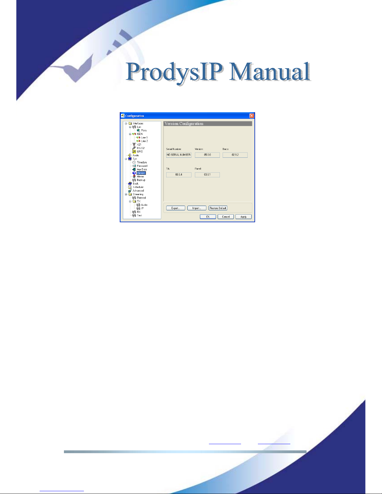
IV.2.4 Software Versions
IV.2.5 Alarm paging
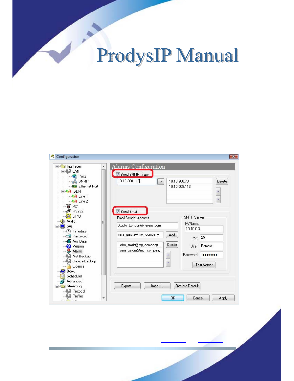
This menu is available for setting alarm paging over IP networks. Notifications
are available by means of:
SNMP traps
SMTP email
Please refer to section IV.8 for details on the user Alarm configuration.
The user might enter multiple IP destinations for SNMP traps to be sent. Usually
a Network Management Tool will display and log the alarm information
accordingly. Integration of the Prodys IP Family of codecs into an overall
customer network operation and management centre is feasible with this
protocol.
These SNMP traps will notify any event status selected, this is, an SNMP trap will
be sent when an alarm is activated or deactivated, including timestamp and
further information.
Page 47
Prodys S.L. Tel: +34 91 6896880 Θ Fax: +34 91 6943777 Θ Email: [email protected] Θ Web: www.prodys.com
Page 47
A complementary or alternate alarm paging tool is to notify via email. Several
email destinations might be selected for automated notification of events.
The alarm paging by email requires to configure the proper mail server
parameters as:
<IP/Host Name>: any valid IP address or Host Name for the SMTP
Server.
<Port>: default SMTP port is 25.
<User>: User to access to the SMTP services.
<Password>: Password to access to the SMTP services.
Page 48
Prodys S.L. Tel: +34 91 6896880 Θ Fax: +34 91 6943777 Θ Email: [email protected] Θ Web: www.prodys.com
Page 48
IV.2.6 Net Backup
Network Backup Configuration. The Prodys IP Family codec allows the user to
use the ISDN line as a backup when the unit works in IP or X21 mode. Please
referrer to section 0 for details.
IV.2.7 Device Backup
The Device Backup feature provides N+1 (including 1+1) protection switch
algorithm for multi codec facilities. Please refer to section V.10 for details.
IV.2.8 License
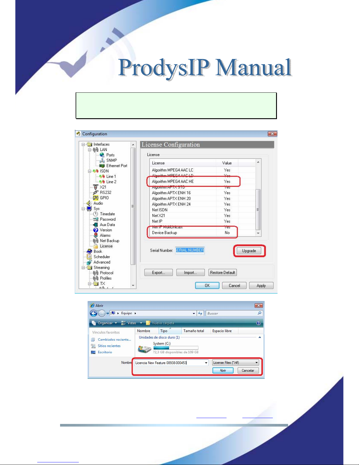
Some codec features are licensed by Prodys and are not available for the factory
default. This allows Prodys to meet different pricing policy according the real
customer requirement for advanced features.
The user might check and update the codec licenses for new features at the
<License> menu.
<Yes>: The feature is licensed for this codec (i.e. for this serial number).
<No>: The feature is not available for this codec.
Steps for upgrading the feature licenses are:
Contact [email protected]
for the new feature with indication of the
codec <Serial Number>. The serial number is displayed on the <License>
menu.
The user is provided with a License File by Prodys
Press de <Upgrade> option on the <License> menu.
Upload the License File from the computer directory to the codec.
Page 49
Prodys S.L. Tel: +34 91 6896880 Θ Fax: +34 91 6943777 Θ Email: [email protected] Θ Web: www.prodys.com
Page 49
It is noted that the feature license is valid for any future Prodys IP Family versions.
In other words the user is allowed to update the codec version any times, the
feature license will not be revoked by the version update process.
Page 50
Prodys S.L. Tel: +34 91 6896880 Θ Fax: +34 91 6943777 Θ Email: [email protected] Θ Web: www.prodys.com
Page 50
IV.3 Book index
When the BOOK menu is selected, the phone book window is displayed on the
right side. The Book index records the user name, a telephone number
(optionally two), an IP address. Up to 64 registers are available.
The Book index keeps ISDN and IP destinations apart. Therefore for accessing the
ISDN Book index the codec must be set to the NET=ISDN. Conversely for
accessing the IP Book index the codec must be set to the NET=IP.
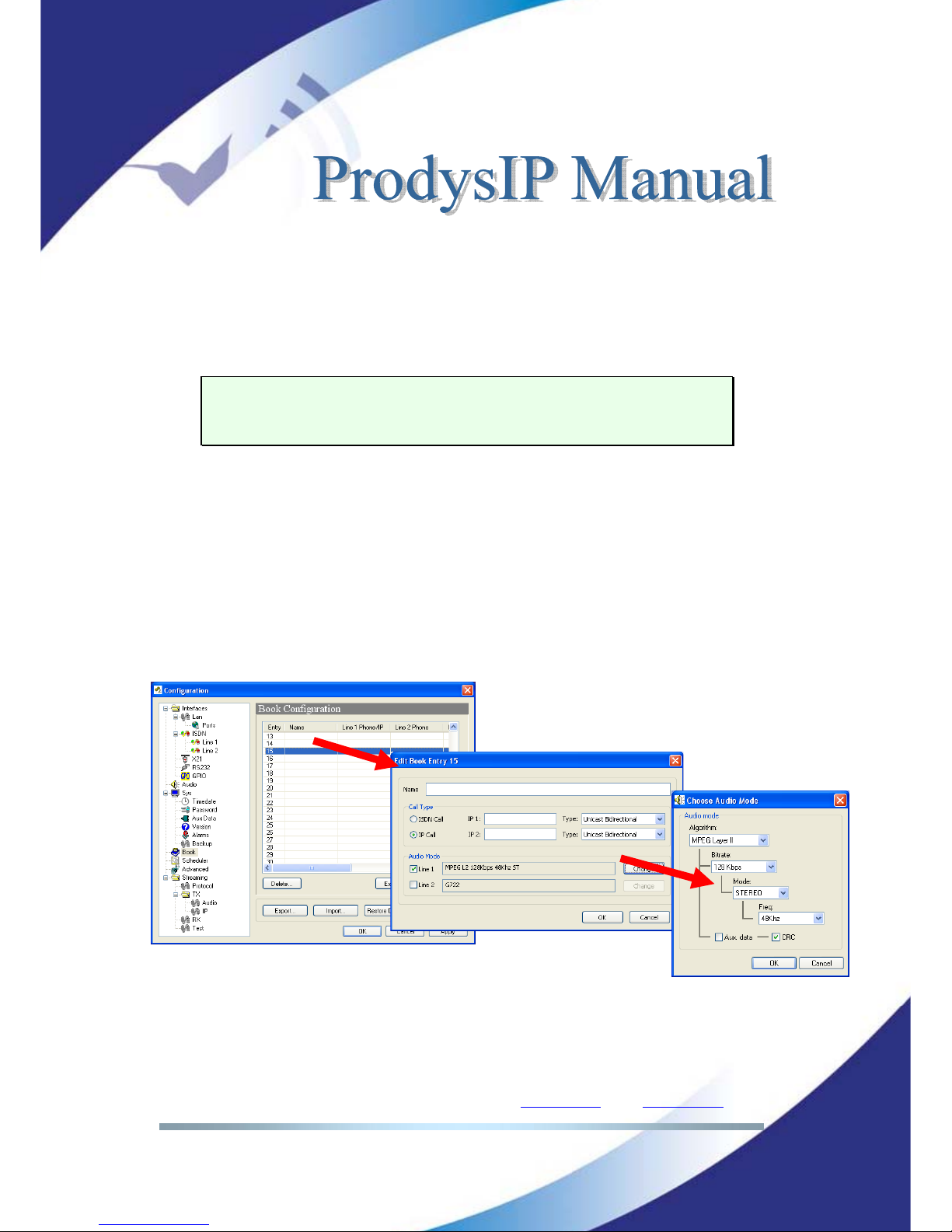
The proceeding to edit a phone book index is as follows:
1. To select one index by clicking on its area.
2. To select ISDN numbers or IP Address depending on which network will
be used. Only it is possible to select one of them.
3. To enter the ISDN number/numbers or the IP address according to the
before selection.
4. To configure the encoder is optional. In case of that it is not entered, the
unit will proceed to call in the current encoder configuration.
Page 51
Prodys S.L. Tel: +34 91 6896880 Θ Fax: +34 91 6943777 Θ Email: [email protected] Θ Web: www.prodys.com
Page 51
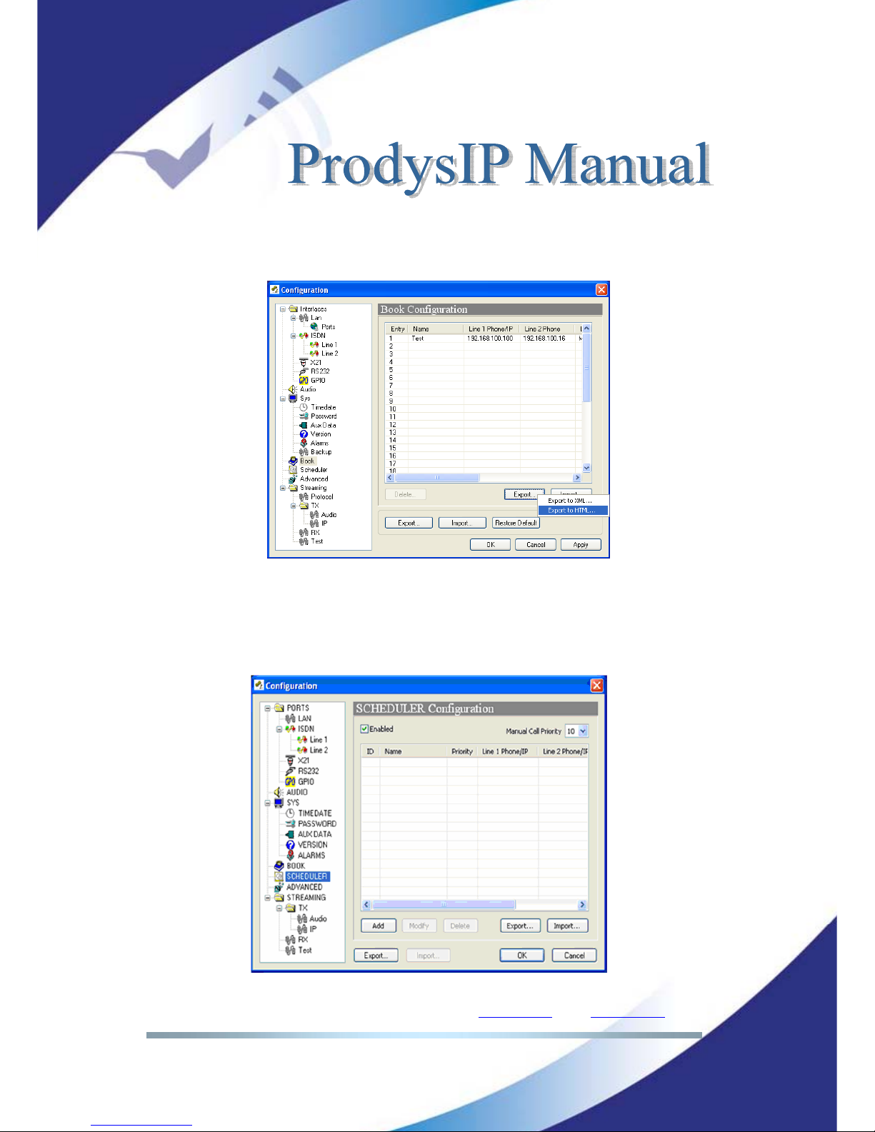
The user is allowed exporting to or import from the Book in XML format on the
computer disk. Additional options are preview end printing of the index content.
IV.4 Scheduler
The Scheduler allows the user to program calls to be dialled automatically. In
addition, the duration and the period for each call can be defined.
Page 52
Prodys S.L. Tel: +34 91 6896880 Θ Fax: +34 91 6943777 Θ Email: [email protected] Θ Web: www.prodys.com
Page 52
IV.4.1 Enabling and disabling the Scheduler
The Scheduler dialog has a checkbox which allows the activation/deactivation of
the Scheduler. When the Scheduler system is disabled, none of the scheduled
calls will progress. In addition, each scheduled call can be enabled/disabled one
by one.
IV.4.2 Automatic and manual call
It is possible to define the precedence for manual or for automatic calls. Thus,
the user can decide if one automatic call will take precedence over a manual
one. The call priority can be set to a number between 1 and 10 (highest priority).
The codec will dial any higher prioritized scheduled call against any ongoing
lower prioritized call. The default priority for automatic calls is 1, and the default
one for manual calls is 10. Manual calls mean those initiated by the user from the
web browser control. It is possible to modify the default priority for the manual
calls from the Scheduler dialog, by changing the value of the field ‘Manual call
priority’.
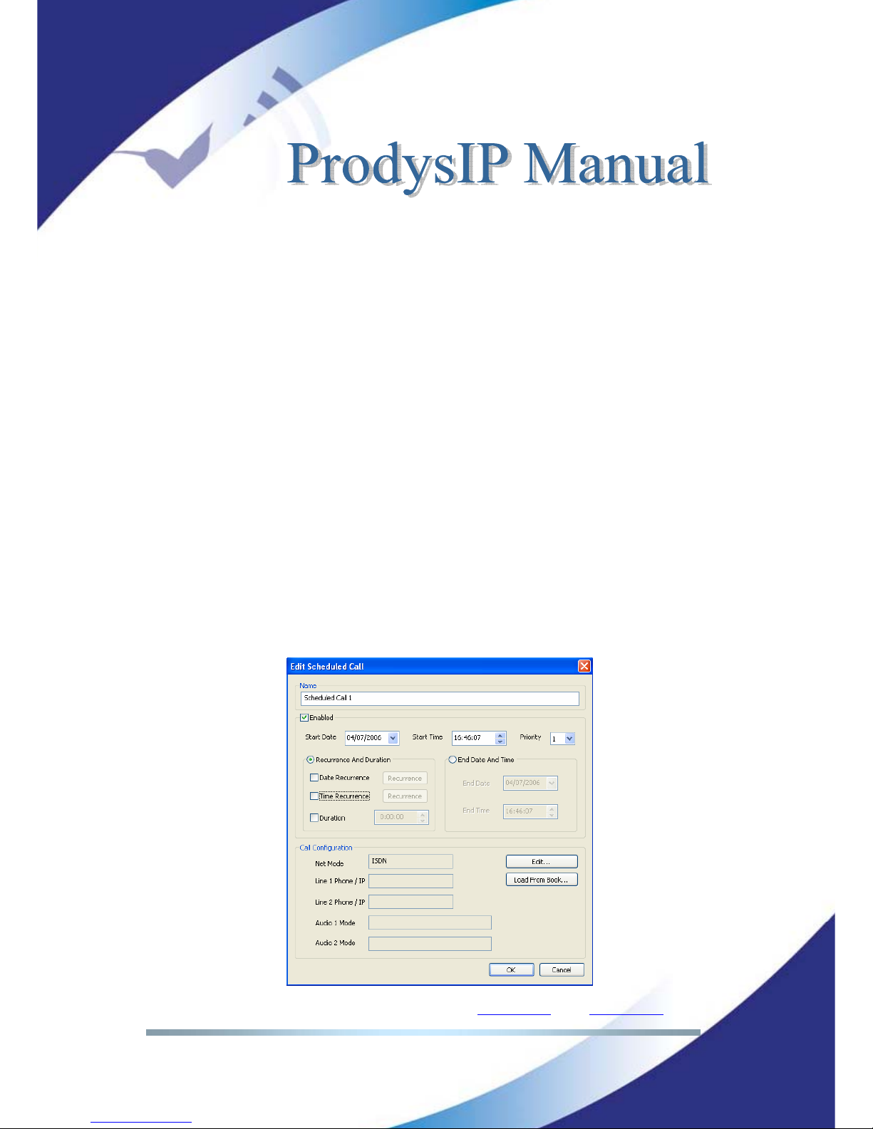
IV.4.3 Programming the scheduler
To add a new automatic dial, click on the ‘Add’ button in the Scheduler
configuration window. The following window will be displayed:
Page 53
Prodys S.L. Tel: +34 91 6896880 Θ Fax: +34 91 6943777 Θ Email: [email protected] Θ Web: www.prodys.com
Page 53
This dialog allows the user to configure all the parameters related to an
automatic dial.
<Name>: This field allows the user to enter a brief description to identify this
call. This name will appear in the call list of the Scheduler. By default, the name
will be “Scheduled Call” followed by a number.
<Start>: The “Start Date” and “Start Time” fields permit the user to configure
the date and time when the scheduled call or pattern will be enabled.
<Priority>: By clicking on “Priority” the user can change the priority value
assigned to the current entry.
<End>: There are two methods to define how long the call will last: “Recurrence
and duration” and “End date and Time”.
o “Recurrence and duration”
This option allows the programming of call repetitions based on time or date:
Time recurrence and Date recurrence.
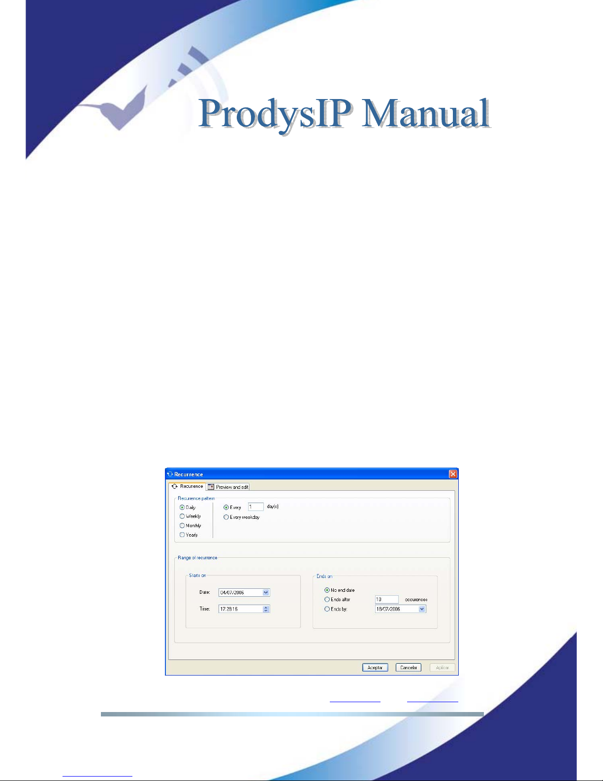
To configure the unit for “Date recurrence” mark the corresponding checkbox in
the Scheduler configuration window and click on <Recurrence>. The following
window will be displayed:
Page 54
Prodys S.L. Tel: +34 91 6896880 Θ Fax: +34 91 6943777 Θ Email: [email protected] Θ Web: www.prodys.com
Page 54
This window is arranged in two different sections:
<Recurrence pattern>: This section allows the user to configure the dates
when the call will be made. It is possible to program daily, weekly,
monthly and yearly patterns.
<Range of recurrence>: This section is divided in two different parts:
o <Starts on>: This option sets the start date and time for the
configured pattern.
o <Ends on>: It is possible to define the end of the configured
pattern in three different ways: Without an end date, after a
certain number of repetitions, or for a specific date.
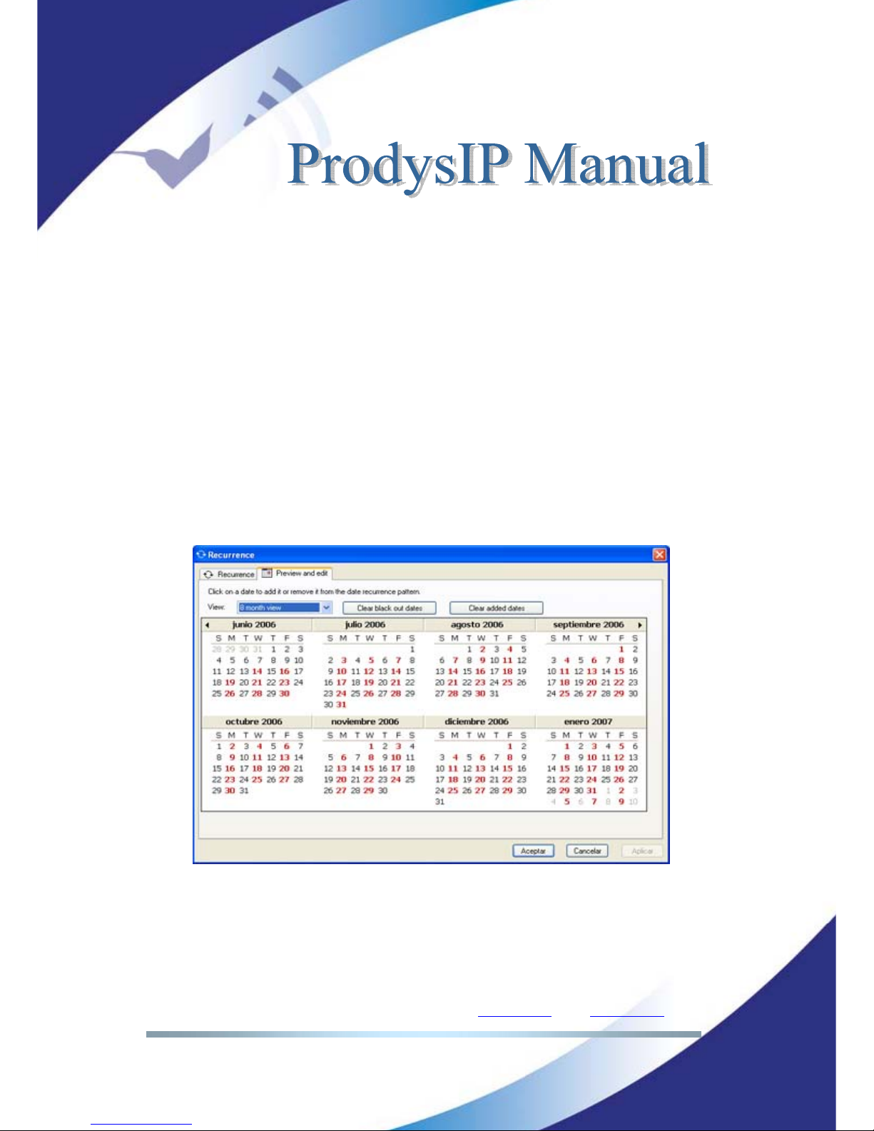
By clicking on <Preview and edit> tab, the user will obtain a calendar wherein
those days when this pattern is active will be coloured on red.
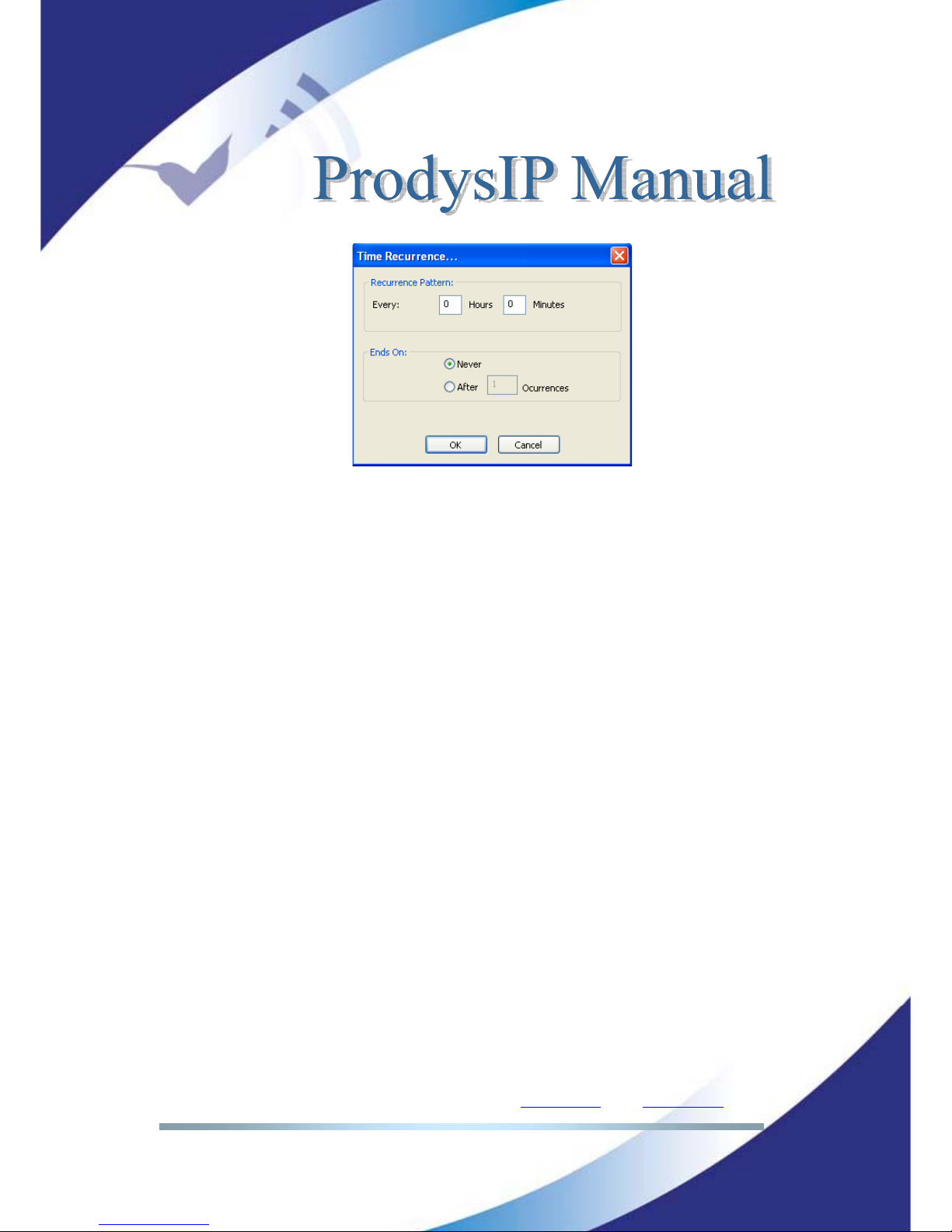
To configure the unit for <Time recurrence> mark the corresponding checkbox
in the Scheduler configuration window and click on <Recurrence>. The following
window will be displayed:
Page 55
Prodys S.L. Tel: +34 91 6896880 Θ Fax: +34 91 6943777 Θ Email: [email protected] Θ Web: www.prodys.com
Page 55
This window is arranged in two different sections:
- “Recurrence pattern”: This section permits the user to configure the
period of time for this call to be repeated.
- “Ends on”: From here, it is possible to establish the end of this
recurrence. It can be never or after an specific number of
occurrences.
o “End date and time”
This option allows the user to establish the duration of a programmed call by
defining the end time and date. The call will be established in the date and time
defined by the “Start Date” and “Start Time” fields.
IV.4.4 Scheduled call configuration
It is necessary to configure the type of network, the numbers and the
compression mode that will be used for call establishment. To do that, the user
can configure these parameters manually, or automatically, by getting them from
one of the entries of the phone book.
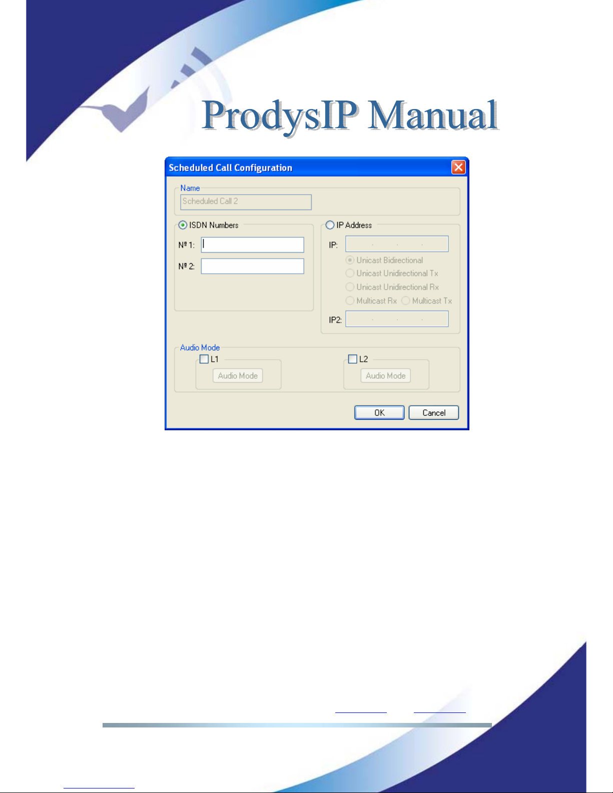
IV.4.5 Manual configuration
To configure these parameters manually, clic on “Edit…”. The following dialog
will be displayed:
Page 56
Prodys S.L. Tel: +34 91 6896880 Θ Fax: +34 91 6943777 Θ Email: [email protected] Θ Web: www.prodys.com
Page 56
From this window the user can enter all the parameters involved in a call
establishment.
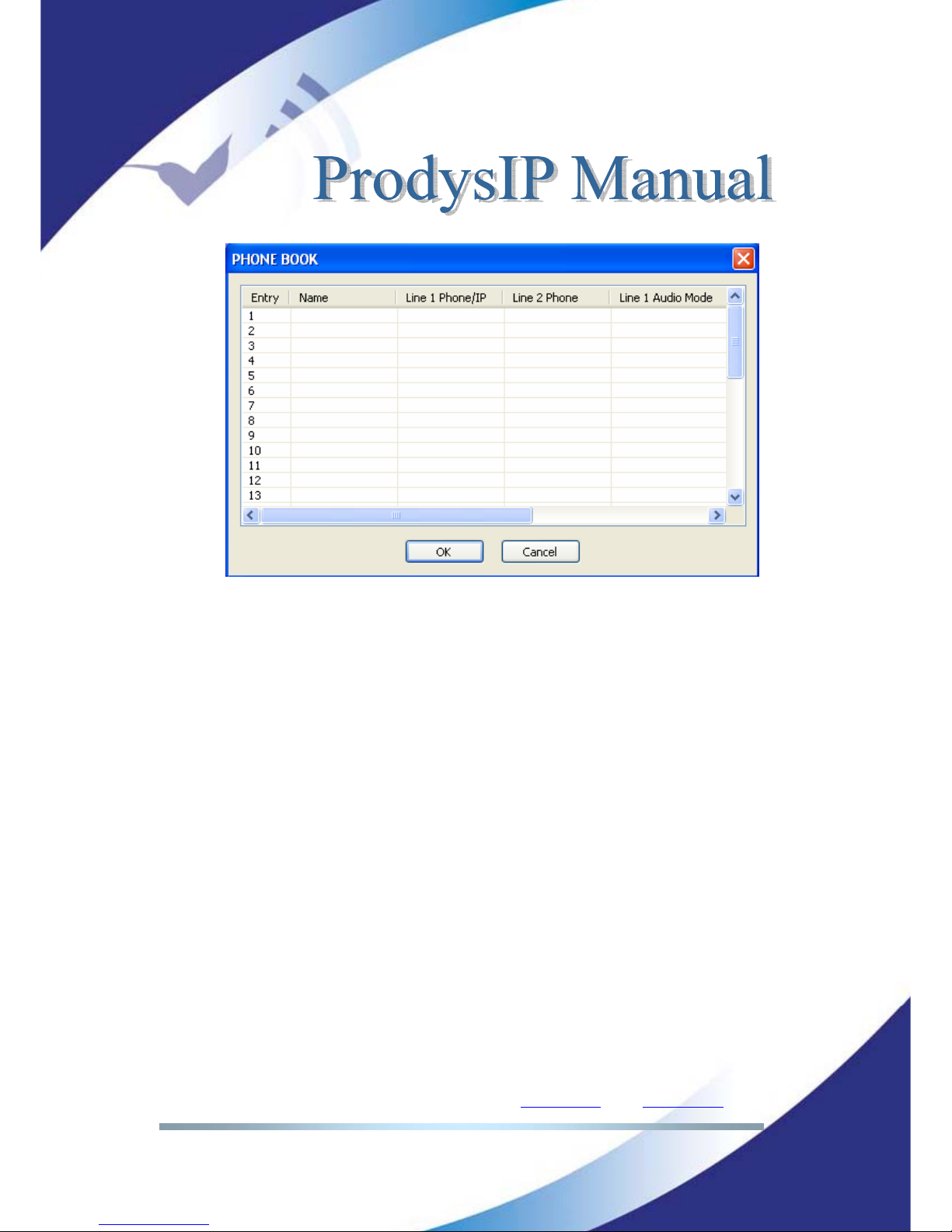
IV.4.5.1. Automatic configuration from the phone book
To configure these parameters automatically, click on “Load From Book…” A
window with all the entries of the phone book will appear. From this window the
user can select any of the existing entries by clicking on any of them and on the
OK button. The selected entry will be read and its configuration will be stored for
the current pattern.
Page 57
Prodys S.L. Tel: +34 91 6896880 Θ Fax: +34 91 6943777 Θ Email: [email protected] Θ Web: www.prodys.com
Page 57
IV.4.6 Modifying existing scheduled calls
To modify a pattern or scheduled call, the user has to select one scheduled call
from the Scheduler list on the Scheduler Configuration Window. Then, by clicking
on “Modify”, the user will be able to edit all the parameters related to the select
pattern.
IV.4.7 Deleting existing scheduled calls
To delete a pattern or scheduled call, the user has to select one scheduled call
from the Scheduler list on the Scheduler Configuration Window. Then, by clicking
on “Delete”, the select pattern will be deleted.
IV.4.8 Copying and pasting scheduled calls
From the Scheduler configuration window, the user can copy and paste
previously configured scheduled calls.
To copy a pattern, select one from the list and right-click on it and select the
option <Copy Call(s)>.
To paste a pattern, select one from the list and right-click on it and select
the option <Paste Call(s)>.
Page 58
Prodys S.L. Tel: +34 91 6896880 Θ Fax: +34 91 6943777 Θ Email: [email protected] Θ Web: www.prodys.com
Page 58
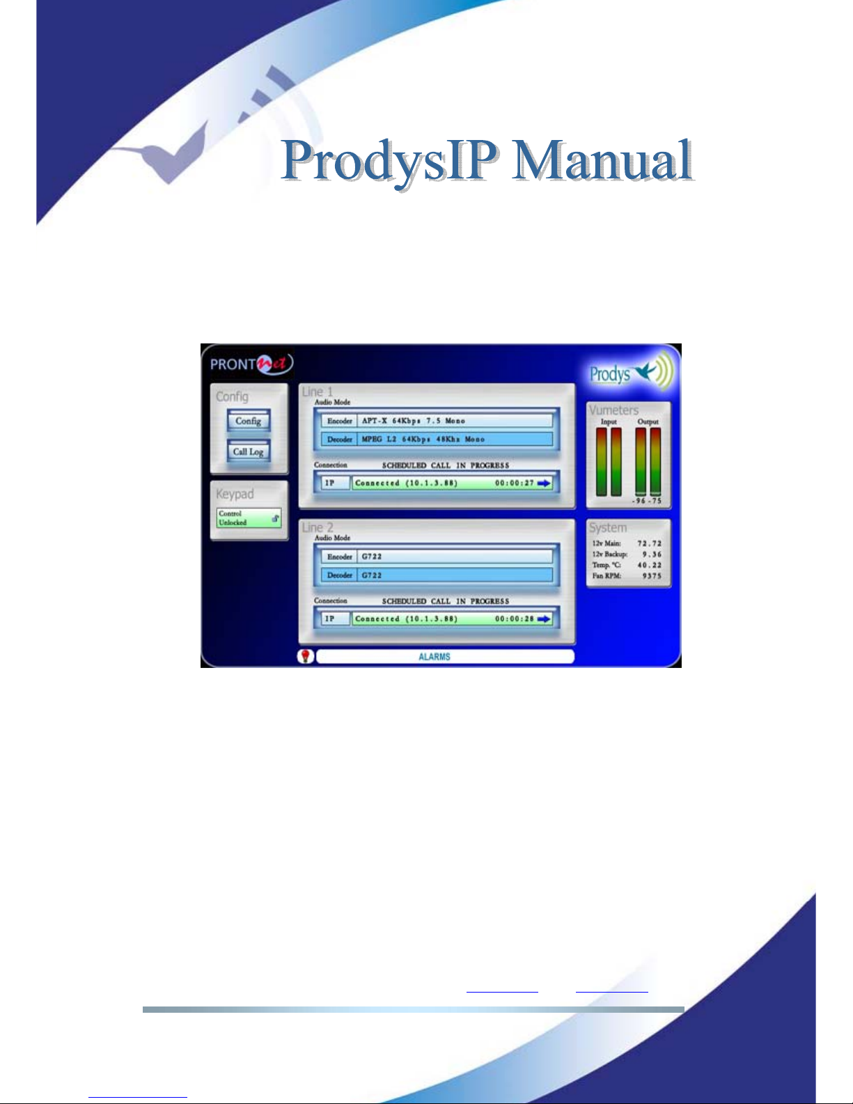
IV.4.9 Monitoring scheduled calls
When one call related to one of the patterns defined in the scheduler of the unit
is in progress, the message “SCHEDULED CALL IN PROGRESS” will be displayed
on the web page for the duration of the call.
Page 59
Prodys S.L. Tel: +34 91 6896880 Θ Fax: +34 91 6943777 Θ Email: [email protected] Θ Web: www.prodys.com
Page 59
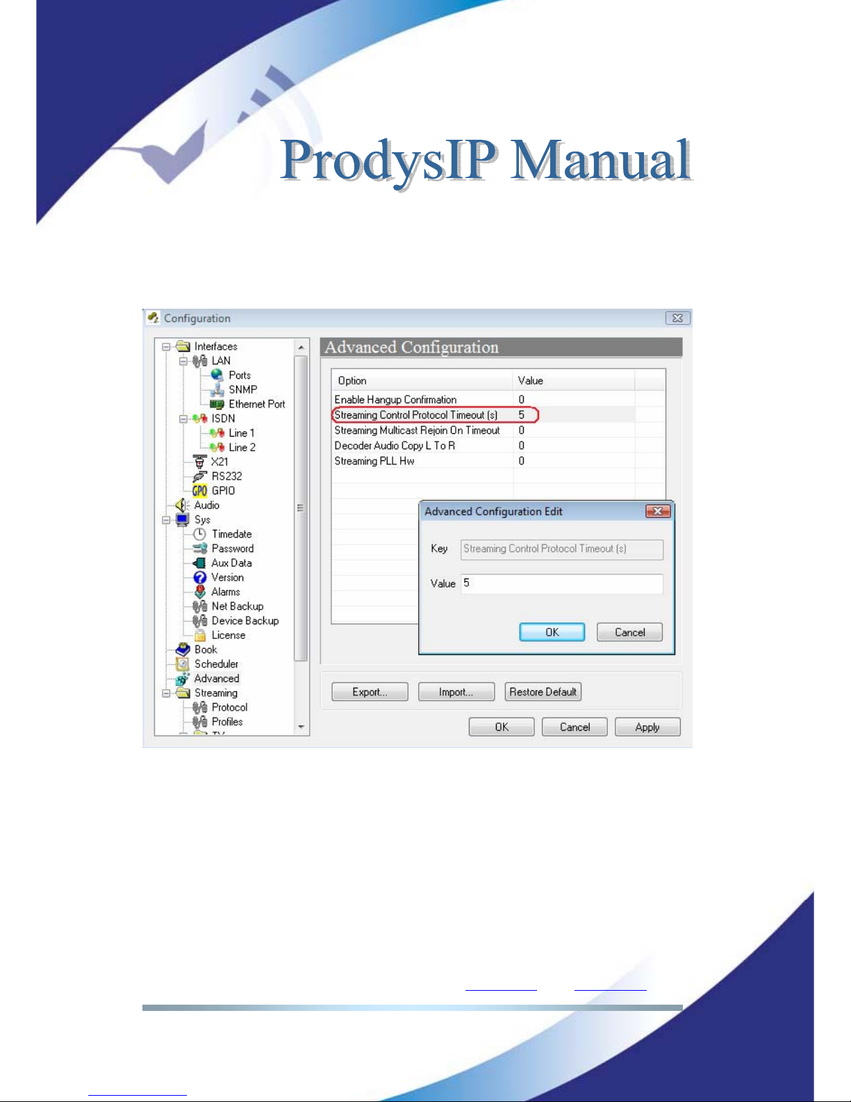
IV.5 Advanced Configuration
Advanced configuration parameters might be set on this dialog box. For any
modification of the current value double click the proper option.
<Enable Hangup Confirmation>: If the value is <1>, the application will ask
confirmation before disconeccting the line.
<Streaming Control Protocol Timeout>: When the link is down, or the mate
codec is unreachable for the specified number of seconds, the audio connection
drops automatically. After the protocol timeout a new communication might be
started.
<Streaming Multicast Rejoin On Timeout>: IGMP protocol functionality.
Page 60
Prodys S.L. Tel: +34 91 6896880 Θ Fax: +34 91 6943777 Θ Email: [email protected] Θ Web: www.prodys.com
Page 60
<Decoder Audio Copy L to R>: This option is enabled with value <1>. This
feature is mainly valuable for hearing mono decoded signals on the left and right
output channel.
<Streaming PLL HW>: Please, cotact [email protected]
for further information
about this. The default and advisable value for this parameter is <0>.
IV.6 Streaming
The Streaming folder displays several menus which provide the user access to
the key IP network parameters:
Selection of a communication protocol compatible with the mate codec.
Adaptation to the actual network performance.
Information about the audio streaming efficiency over the IP network,
delay, etc.
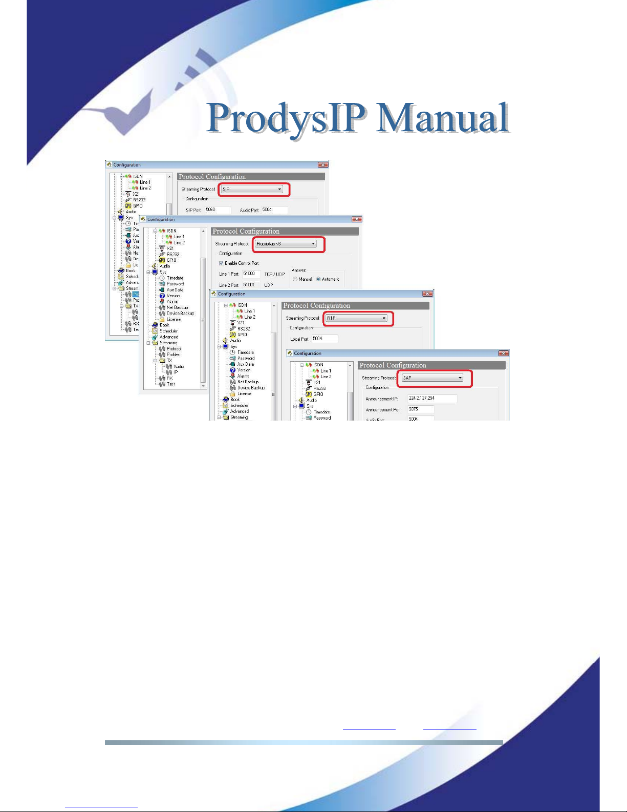
IV.6.1 Protocols
Several communication protocols are available for starting, monitoring and
ending an audio stream over the IP network. From now on those are referred to
as just “protocols”.
The list of protocols available for Audio over IP streaming is as follows:
Proprietary
Proprietary V2
Proprietary V3
CCS NetStar /AudioStar
RTP
SIP
SAP
Page 61
Prodys S.L. Tel: +34 91 6896880 Θ Fax: +34 91 6943777 Θ Email: [email protected] Θ Web: www.prodys.com
Page 61
IV.6.2 Proprietary Protocol (V1)
This is Prodys` legacy IP protocol since 2004. It has been proven to be very
robust and useful for a broad amount of customers.
Selection of sub-parameters are not applicable for this protocol, therefore this
menu is blank. However the user should keep in mind that the factory default
configuration for Proprietary Protocol V1 is affected by the menu <Port
Configuration> (please refer to IV.1.2).
Information for advanced users is available at V.6.4.
IV.6.3 Proprietary Protocol (V2)
Prodys` second IP protocol enhances the former V1 protocol with additional
network performance monitoring features like Lost or Disordered Packets. keep
in mind that the factory default configuration for Proprietary Protocol V1 is
affected by the menu <Port Configuration> (please refer to IV.1.2).
Page 62
Prodys S.L. Tel: +34 91 6896880 Θ Fax: +34 91 6943777 Θ Email: [email protected] Θ Web: www.prodys.com
Page 62
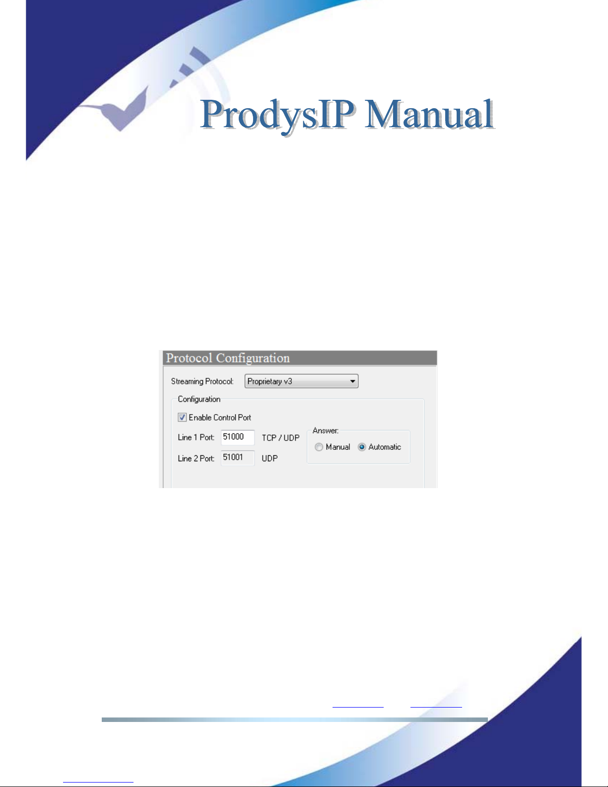
IV.6.4 Proprietary Protocol (V3)
Prodys` third IP protocol is build up with a different approach although any
former features are still available. Prodys’ V3 protocol is aimed to make the
streaming over Internet easy for the user.
More specific, the V3 offer a NAT traversal capacity. This means that the caller
end of a new IP communication does not require asking for router or firewall
adaptation before streaming. This protocol enables to stream from any place like
convention centres, sport stadiums, hotel, etc. without meeting the network
administrator.
At the destination, usually the studio, the gateway must forward the ports
defined at the V3 protocol menu.
Another application for the V3 protocol is allowing one-way IP connections (eg.
satellite or radio links). These applications require disabling the Control Port.
IV.6.5 CCS NetStar /AudioStar protocol
This protocol is applicable if compatibility with CCS Musicam IP codecs is
required.
It is remarked that this protocol does not include automatic procedures for taking
an incoming call or streaming supervision. Therefore the user is required to
enable or disabling manually any incoming or outgoing stream.
Page 63
Prodys S.L. Tel: +34 91 6896880 Θ Fax: +34 91 6943777 Θ Email: [email protected] Θ Web: www.prodys.com
Page 63
IV.6.6 RTP protocol
This protocol performs plain streaming of audio embedded into RTP/UDP
packets. The main application is also compatibility with a very wide choice of
audio streaming devices.
It is remarked that this protocol does not include automatic procedures for taking
an incoming call or streaming supervision. Therefore the user is required to
enable or disabling manually any incoming or outgoing stream.
IV.6.7 SIP
The European Broadcast Union (EBU) is promoting the interoperability of audio
codecs for any manufacturer. For this purpose the use and the application of a
subset of the Internet Protocols has been proposed. This effort will allow to
setup in a friendly way audio streaming communications between several vendor
equipments.
The deployment of SIP Protocol Servers among the network will support calling
remote parties just by invoking their network name regardless of the actual
public o private IP addresses. Neither is required to manage the office routers
and the firewall’s TCP/IP ports for any new communication path.
The physical location, often related to fixed IP addresses or subnets, is not
further meaningful. In this sense, portable audio codecs will profit with an easy
call procedure. Neither is required to agree ahead on the audio compression type
and data stream rate, because the SIP Protocol manages by itself to negotiate
the convenient communication details with the remote party.
For Prodys’ former customers performing a call using SIP is much the same as
using Prodys’ proprietary protocols given that the SIP configuration is set.
SIP supports up to date only unicast streaming. Any Prodys IP Family codec’s
audio compression mode is supported also if SIP protocol is in use.
10
For further
details please refer to the “Technical Description” at this document.
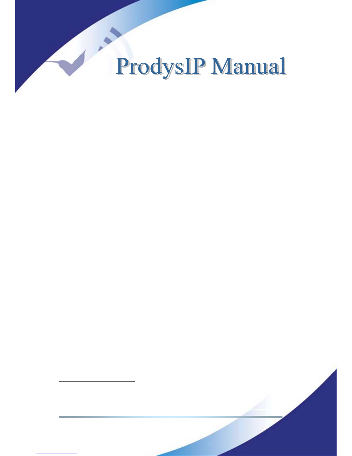
<SIP Port>: TCP/IP port dedicated to SIP signalling for establishing, updating
10
The apt-X compression is still undefined by the EBU Tech 3326 standard. For compatibility
reason this mode is not supported if SIP protocol is selected.
Page 64
Prodys S.L. Tel: +34 91 6896880 Θ Fax: +34 91 6943777 Θ Email: [email protected] Θ Web: www.prodys.com
Page 64
or finishing a call. Port 5060 is mandatory by the standard if direct calls without
gateways are expected.
<Audio Port>: TCP/IP port dedicated to the RTP communication, this is the
actual port for the audio streaming payload. By default the number 5004 is
reserved.
<Public IP Address>: This parameter is necessary when making connections
through a router to the Internet.
11
The user must copy the public IP address
of his router into this box.
<Automatic> or <manual> answer of incoming call request can be defined.
If SIP server support is granted by your network:
<Server IP>: IP address of the SIP Server. At this point is registered
periodically the proper user information for full protocol support.
<Server user> & <Server password>: Some SIP servers requires
authentication before proceeding the register of SIP users.
<Username>: Your alias on the Internet regardless of your current IP
address. By this alias you are identified for other SIP participants.
<Timeout>: Time in seconds before the user information registered at the
previous server is flushed. Therefore the information about the SIP user are
updated from time to time.
<FEC>: Configuration for the Forward Error Correction applicable to the
outgoing audio stream is defined at this section for SIP. For further details on
FEC please refer to section V.6.19.
11
Routers translate local or private IP addresses into public WAN IP addresses (e.g. Internet).
This translation of address is broadly known as NAT.
Page 65
Prodys S.L. Tel: +34 91 6896880 Θ Fax: +34 91 6943777 Θ Email: [email protected] Θ Web: www.prodys.com
Page 65
IV.6.8 SAP
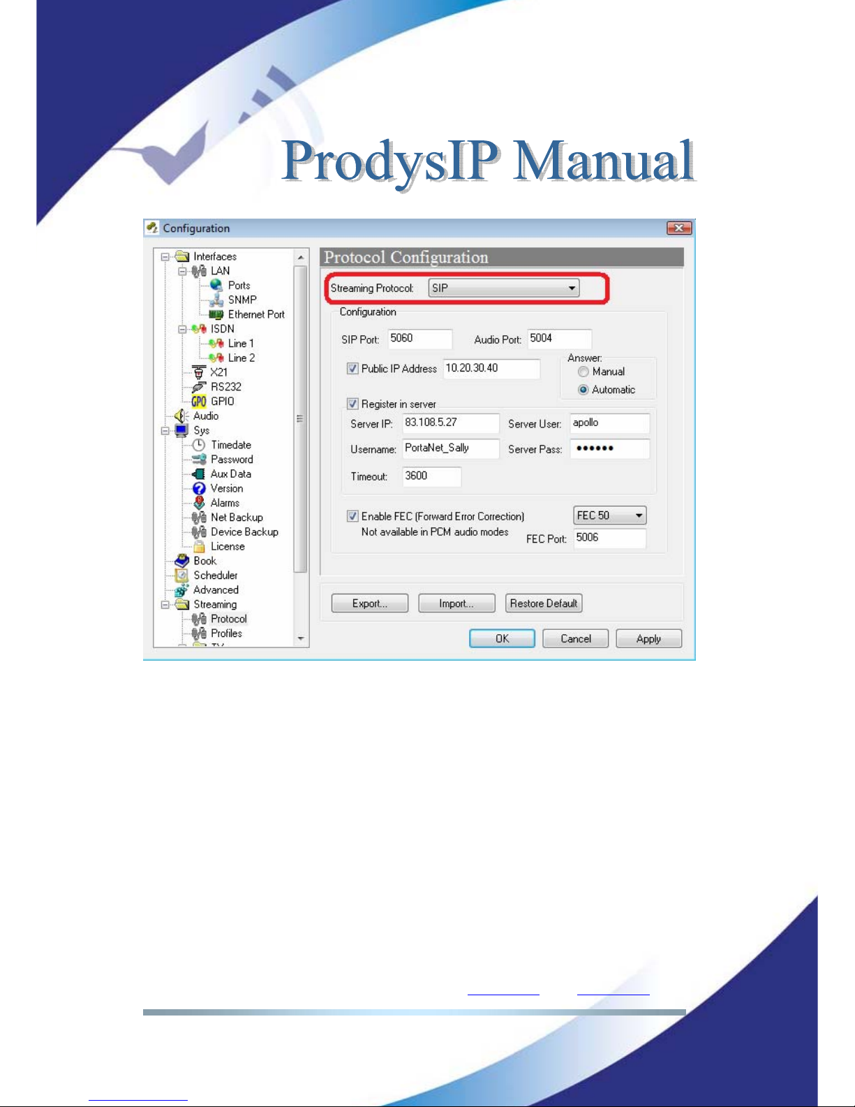
When selecting SAP as communication protocol, only multicast calls will be
available (point-to-multipoint). In addition, the user will have to indicate the
announcement IP address and port on which the audio streaming is ‘announced’.
Page 66
Prodys S.L. Tel: +34 91 6896880 Θ Fax: +34 91 6943777 Θ Email: [email protected] Θ Web: www.prodys.com
Page 66
The default values for these parameters are the default ones defined by the SAP
standard (RFC 2974). This address and port will be used by the transmitter to
‘advert’ its audio streaming broadcasting. In the case that these parameters are
modified by the user, they should be configured to the same values at both
ends, the sender and the receiver.
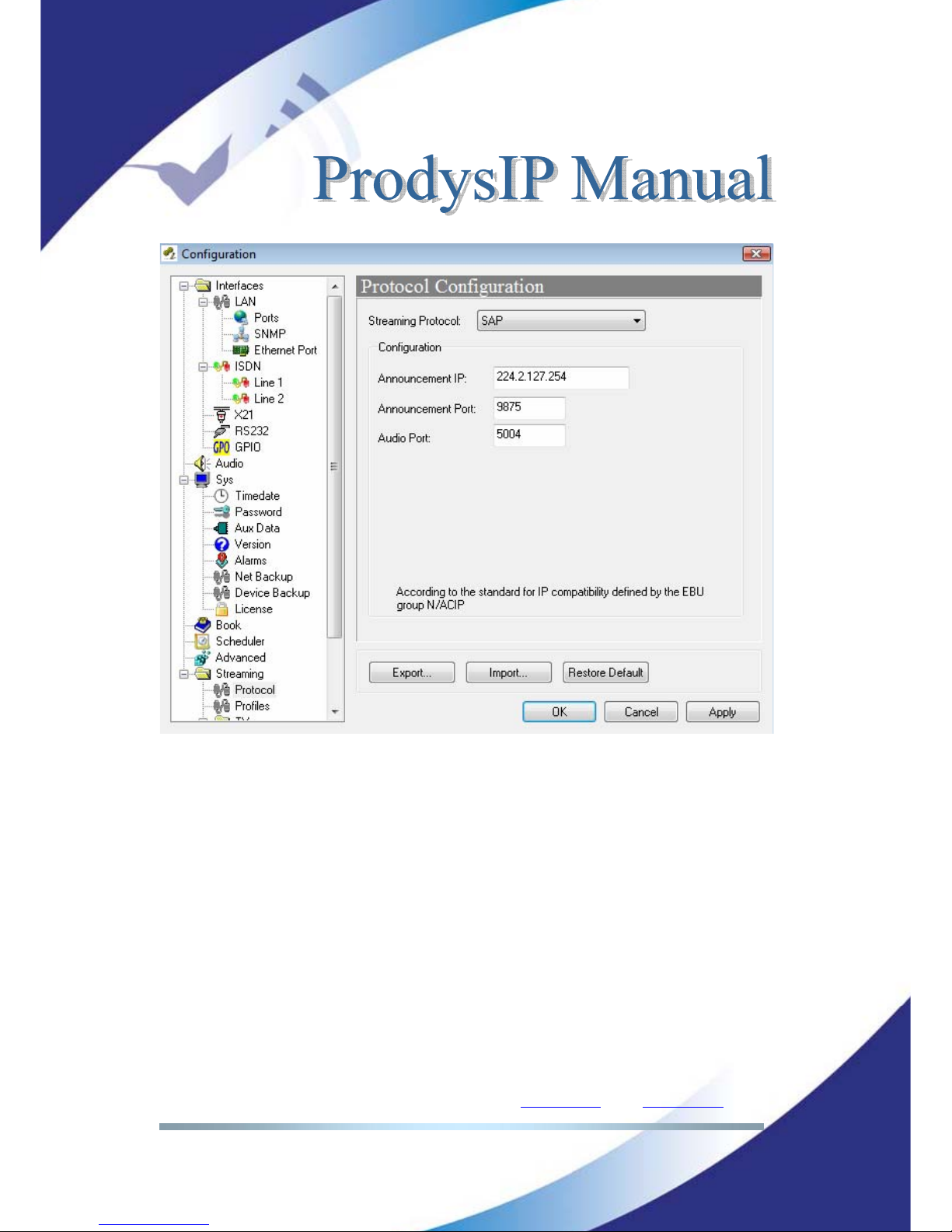
When making a call with SAP as communication protocol, only Multicast Tx and
Multicast Rx call types will be available. To launch an audio streaming over IP
with SAP the user shall select Multicast Tx as call type from the dialing window,
and type in the multicast IP address to send the audio to.
Page 67
Prodys S.L. Tel: +34 91 6896880 Θ Fax: +34 91 6943777 Θ Email: [email protected] Θ Web: www.prodys.com
Page 67
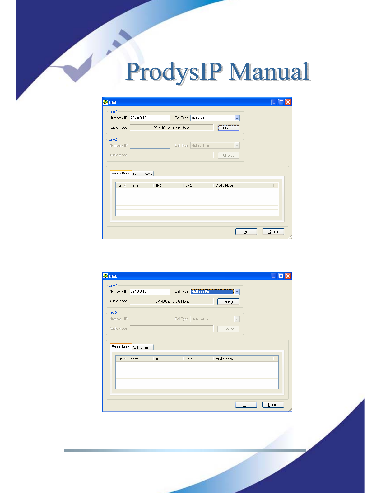
To receive this audio streaming, the user shall select the Multicast Rx call type,
and will introduce the same Multicast IP address as the transmitter.
Page 68
Prodys S.L. Tel: +34 91 6896880 Θ Fax: +34 91 6943777 Θ Email: [email protected] Θ Web: www.prodys.com
Page 68
As many receivers as required can join this multicast address and receive the
audio, without any increment in the required bandwidth, given that this
communication is based on IP multicast technology.
IV.6.9 Profiles for audio streaming over IP Networks
The <Profiles> menu provides a simple and quick shortcut to predefined codec
configurations for audio streaming over IP Networks. Given is that the user might
deal with different IP network performances.
Several predefined network profiles are available:
<Safe>: Suitable for low reliable networks such as Internet.
<Ultra Low delay>: Suitable for high reliable networks such as LAN.
<Custom>: User defined streaming parameters. Please refer to sections
IV.6.10 and IV.6.11 for details.
IV.6.10 Tx
This submenu defines some subtle parameters for fine tuning of the IP protocols.
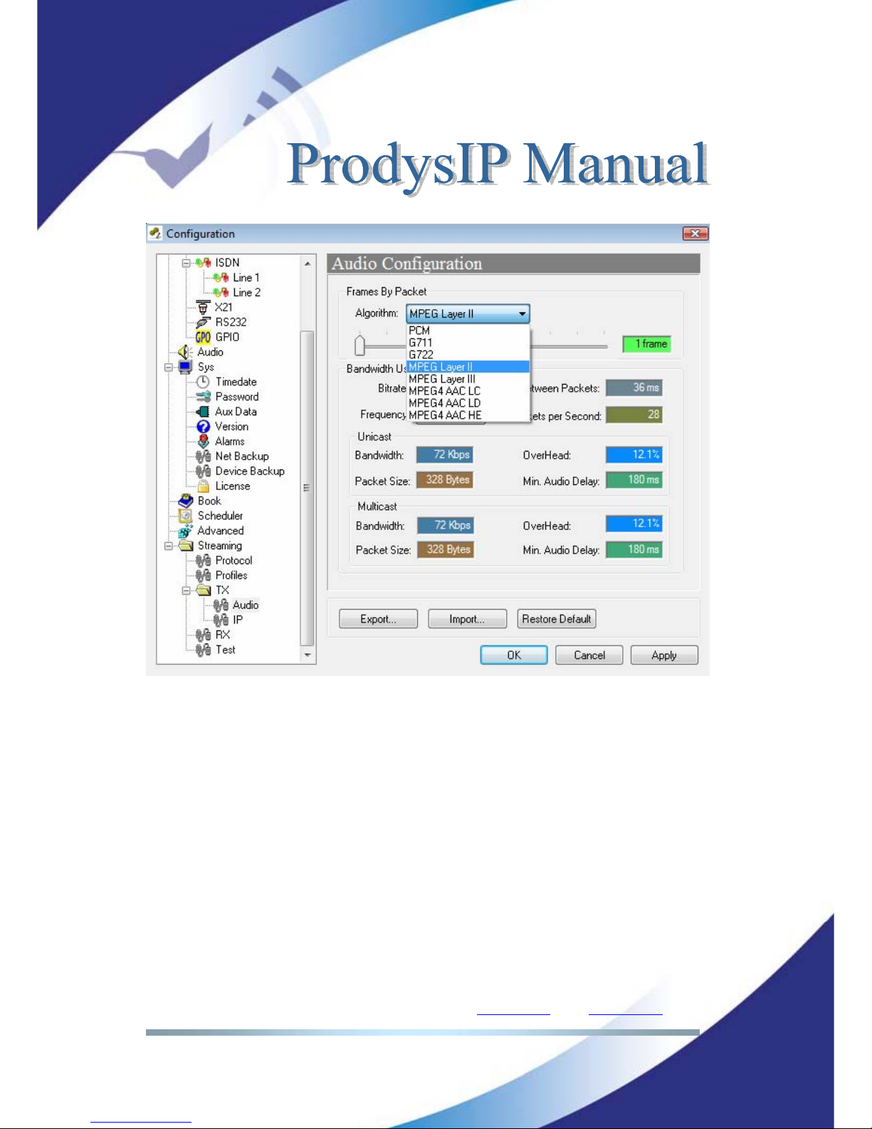
<Audio>: This menu allows the user to configure the audio transmission
parameter (TBP: Time between packets) and to know in advance, the required
bandwidth and delay of the connection.
NOTE: Bear in mind that this is a transmission parameter, so it won’t be available
for those units like ProntoNet IP Decoder, which does not have encoding
capabilities.
Access this by pressing the “SYS” button on the web interface select STREAMING
– TX. You will be presented with a screen similar to below:
Page 69
Prodys S.L. Tel: +34 91 6896880 Θ Fax: +34 91 6943777 Θ Email: [email protected] Θ Web: www.prodys.com
Page 69
From this window, the user can know beforehand, the bandwidth and delay of
the connection.
So, the ‘Time Between Packets’ parameter, is directly related with the packet size
and therefore with the occupied bandwidth (overhead) and delay. Therefore, the
appropriate value for this parameter is a trade off between delay and bandwidth:
The larger the block size (TBP), the higher the delay, but the smaller
the required bandwidth and overhead (more efficient use of IP
packets), and vice versa.
If there is no delay requirements in the connection, it is always advisable to
select the highest value, since bandwidth will be smaller. Also, the more frames
over the network (with small TBP values, frames decrease in size and increase in
number), the more likely it is that the jitter will grow.
Page 70
Prodys S.L. Tel: +34 91 6896880 Θ Fax: +34 91 6943777 Θ Email: [email protected] Θ Web: www.prodys.com
Page 70
NOTE: Keep in mind that there are compression algorithms that introduce delay
itself. When that delay is higher than the TBP minimum value, the value is
automatically adapted to the algorithm to the values shown on the left, and user
is not allowed to change it, given that it does not make sense to increase it and
it is not possible to be decreased due to the codification process.
Remind that the <Tx> menu only defines the operational parameters for several
protocols. For taking in force the actual audio streaming protocol, the user must
apply the selection at the <NET> and the <Protocol> according section III.1.
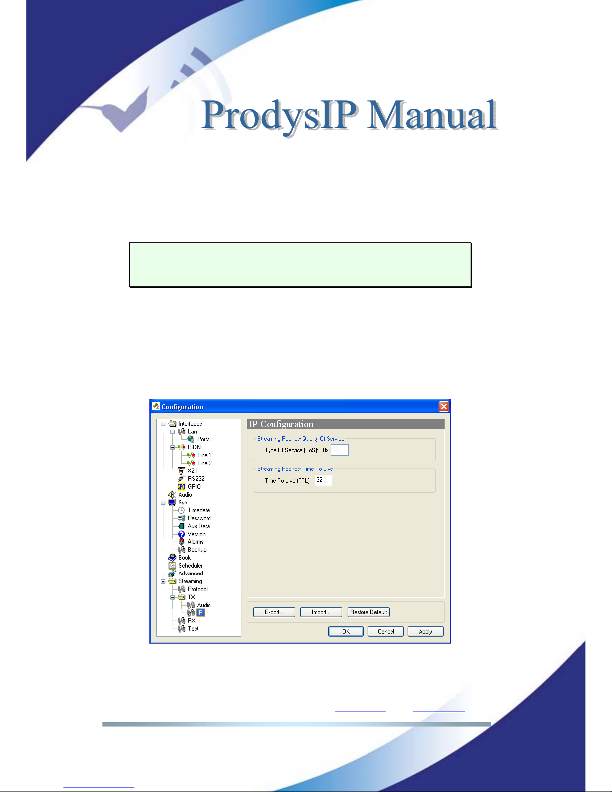
<IP> menu: This menu allows the user to configure some IP header fields
supporting QoS.
- Streaming Packets Quality of Service: This option allows the user to
configure the value in the ToS field in the IP header.
- Streaming packets Time To Live: Configure the Time To Live parameter.
Page 71
Prodys S.L. Tel: +34 91 6896880 Θ Fax: +34 91 6943777 Θ Email: [email protected] Θ Web: www.prodys.com
Page 71
IV.6.11 Rx
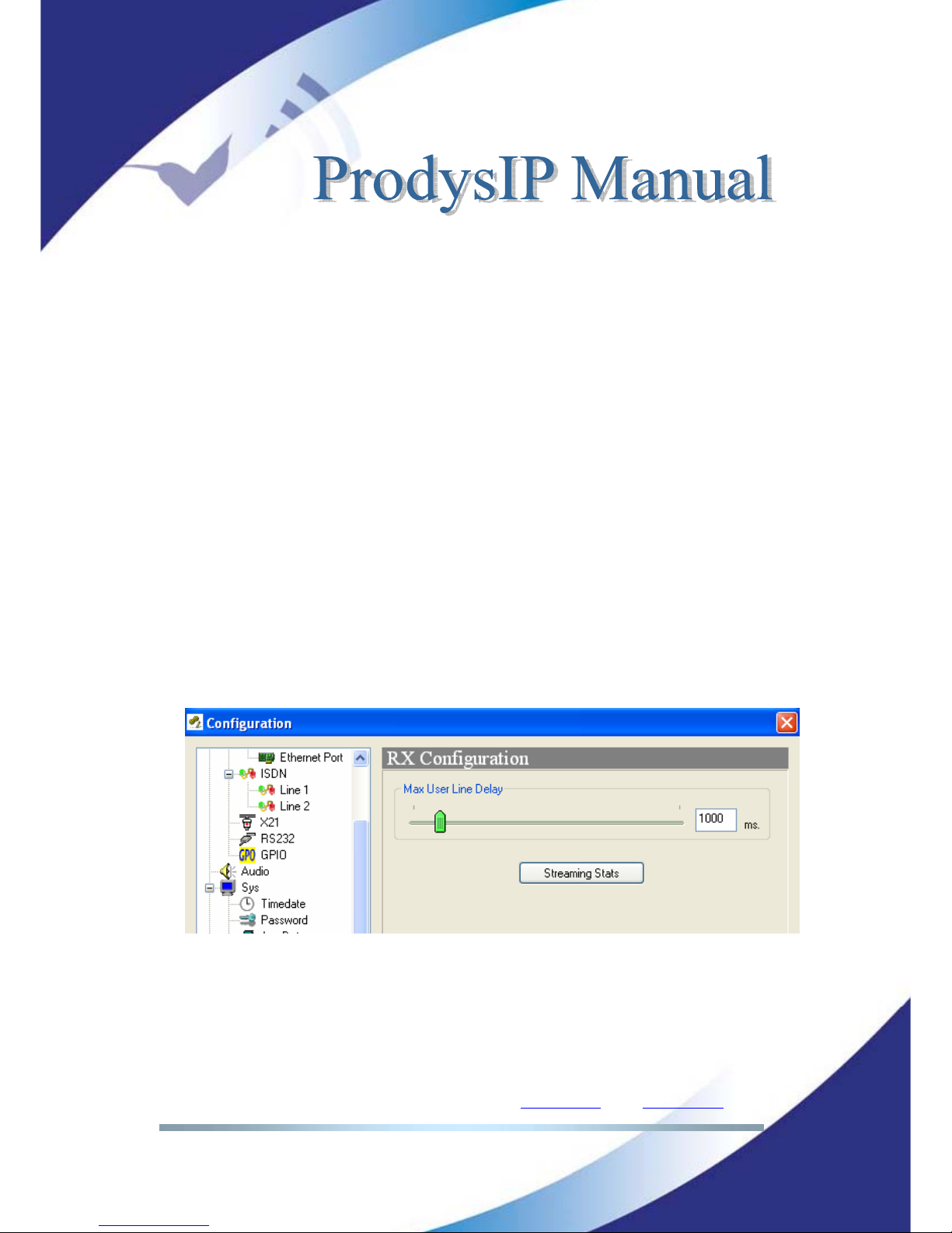
A decisive factor in real time audio streaming is the ‘jitter’, or delay variation. To
deal with the jitter in the connection, Prodys IP Family codec provides a tool
which allows the user to modify the size of the reception buffer, and so, to
compensate the jitter. The maximum value for this buffer is 10s.
Once the user knows the “jitter value” of the IP connection, the jitter buffer
should be set:
“Jitter Value” is the difference between the maximum and minimum delay.
If the jitter value is 0 it means that the delay is constant and it is not
necessary to adjust the jitter correction buffer in the reception side. If the
delay is not constant, it is necessary to adjust the buffer size in order to
guaranty not audio drops, even when the delay reaches the maximum
value.
The unit of this buffer is miliseconds, and the range is 0-10000. The delay
grows as many as the number of miliseconds the buffer has been set to.
The “jitter value” can me measured by the streaming tool commented
before.
Rule: Max User Line Delay + TBP >= Jitter value.
This value can be changed during the audio connection.
Page 72
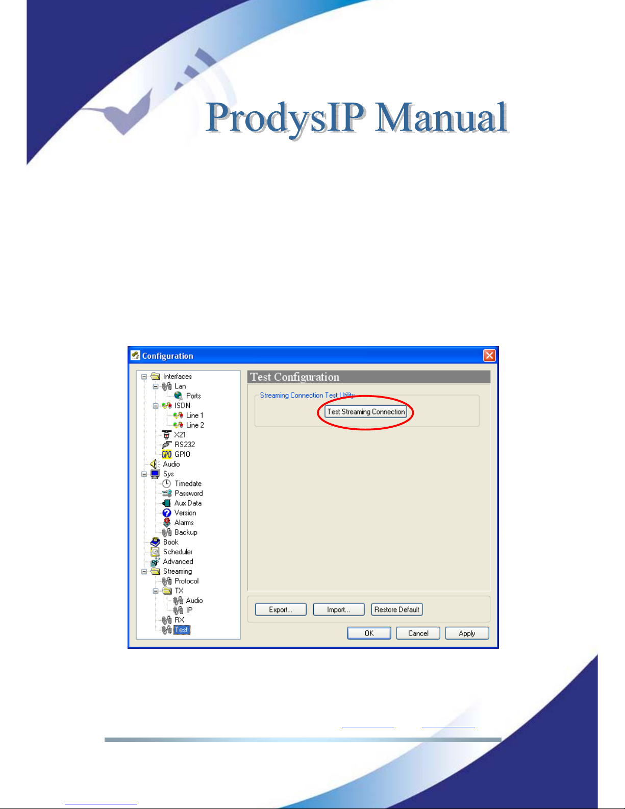
Prodys S.L. Tel: +34 91 6896880 Θ Fax: +34 91 6943777 Θ Email: [email protected] Θ Web: www.prodys.com
Page 72
IV.6.12 Test
This tool allows the user to check, in real time the upload/download bandwidth,
delay, jitter and packet loss in an IP link between two Prodys IP units. This
information will be used to adjust the streaming parameters in order to achieve
the best quality in the audio streaming connection.
Before making an IP connection, be it unicast or multicast, the user should first
check the quality of the IP connection. Prodys IP Codecs comes fitted with a
‘Test Tool’ embedded in the web page. No additional software is required. With
this tool, the user can measure the most important parameters of an IP
connection: Download and upload bandwidth, delay, jitter, lost packets and
packet disorder:
Page 73
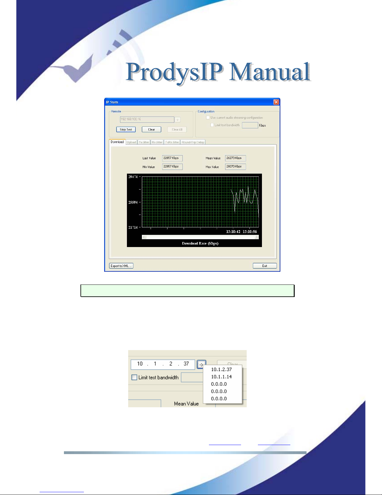
Prodys S.L. Tel: +34 91 6896880 Θ Fax: +34 91 6943777 Θ Email: [email protected] Θ Web: www.prodys.com
Page 73
This tool is only available when lines are disconnected.
How to run the tests:
1.- First of all the user must enter the IP address of the remote Prodys IP Family
codec. This dialog stores the last used IP addresses.
Page 74
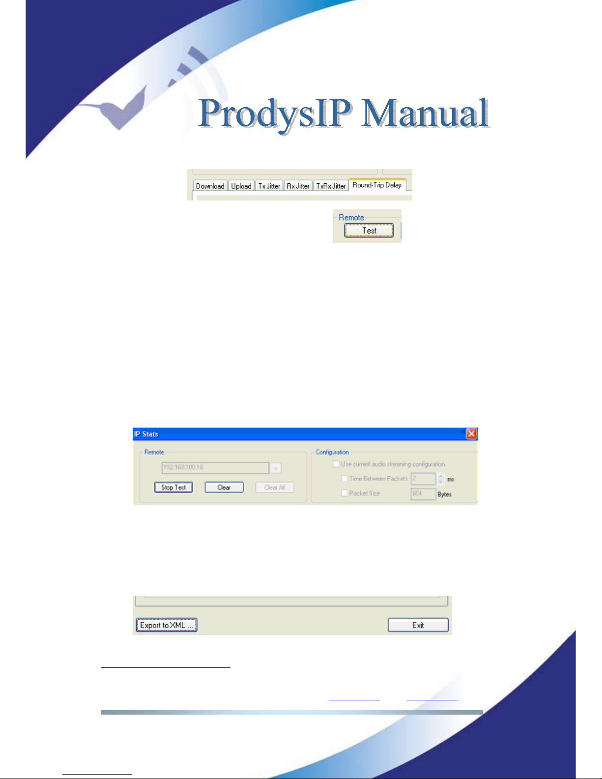
Prodys S.L. Tel: +34 91 6896880 Θ Fax: +34 91 6943777 Θ Email: [email protected] Θ Web: www.prodys.com
Page 74
2.- Select the test you wish to perform.
3.- To run the test just press the test button:
4.- The values will be shown in a graph, as well as the max, min, last, and
mean(avg) values.
4.- Press "STOP" to stop the test or "CLEAR" to reset the readings.
5.- The user can limit the bandwidth used by the test tool:
By default this test will attempt to send as much IP traffic as possible. If
you are using this test on a "live" network then it is desirable to limit the test
bandwidth to that which will actually be used. It is also possible to simulate the
same packet rate and bandwidth as that configured for the audio connection
12
.
An accurate figure of total bandwidth used (audio data + overhead) can
be obtained from the "Audio Configuration" screen.
Once the test is finished, it is possible to export the results to an XML file.
12
Available from version 5.0.0 onwards.
Page 75
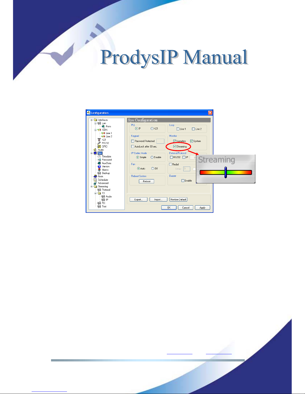
Prodys S.L. Tel: +34 91 6896880 Θ Fax: +34 91 6943777 Θ Email: [email protected] Θ Web: www.prodys.com
Page 75
IV.6.13 Real Time Analyzer
It is possible to monitor the streaming operation in real time by ticking a
checkbox.
That indication represents the instant decoder buffer occupation.
When indication is green or even yellow means the streaming is working fine.
Depending on the algorithm, the variation will be quicker or slower but always
should be going up and down from yellow to the center (green).
If the bar moves towards the red area, it means that it is getting closer to
buffer overflow (red right) or buffer underflow (red left). Of course, if you have
buffer overflow or underflow you will have a cut in the audio. If the indication
goes to red for an instant, usually doesn't affect the streaming, but of course, if
you have a constant red indication you are having problems with the streaming.
Buffer underflow might be caused by lost packets or because the clock of the AD
converter at the transmitter side which runs slower than the DA converter at the
receiver side.
Page 76
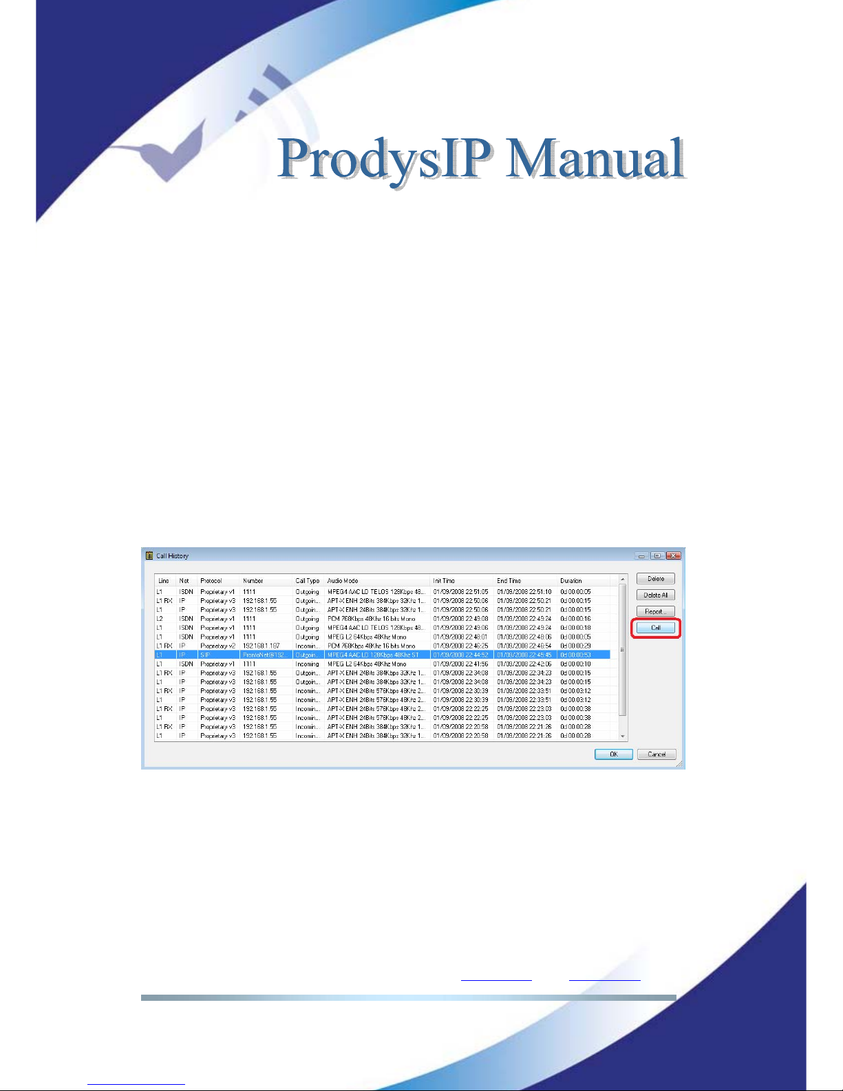
Prodys S.L. Tel: +34 91 6896880 Θ Fax: +34 91 6943777 Θ Email: [email protected] Θ Web: www.prodys.com
Page 76
Buffer overflow might be caused by the opposite scheme: The clock at the
transmitter side is running quicker than the clock at the receiver side.
Prodys PPL adjustment mechanism is aimed at dealing with this clock jitter and
thus to compensate for this variation and guarantee proper audio over IP.
IV.7 Call Log
An history report has been included to record the input and output calls
according to the following information: telephone/IP, audio modes, date and
start/end time, length of each call, etc…
A report of the calls in html can be created allowing preview and print.
A dial short cut is possible from the Call Log window. The user might restart the
communication with the same NET parameter, destination ID and audio
compression mode as any of the former communications logged.
Page 77
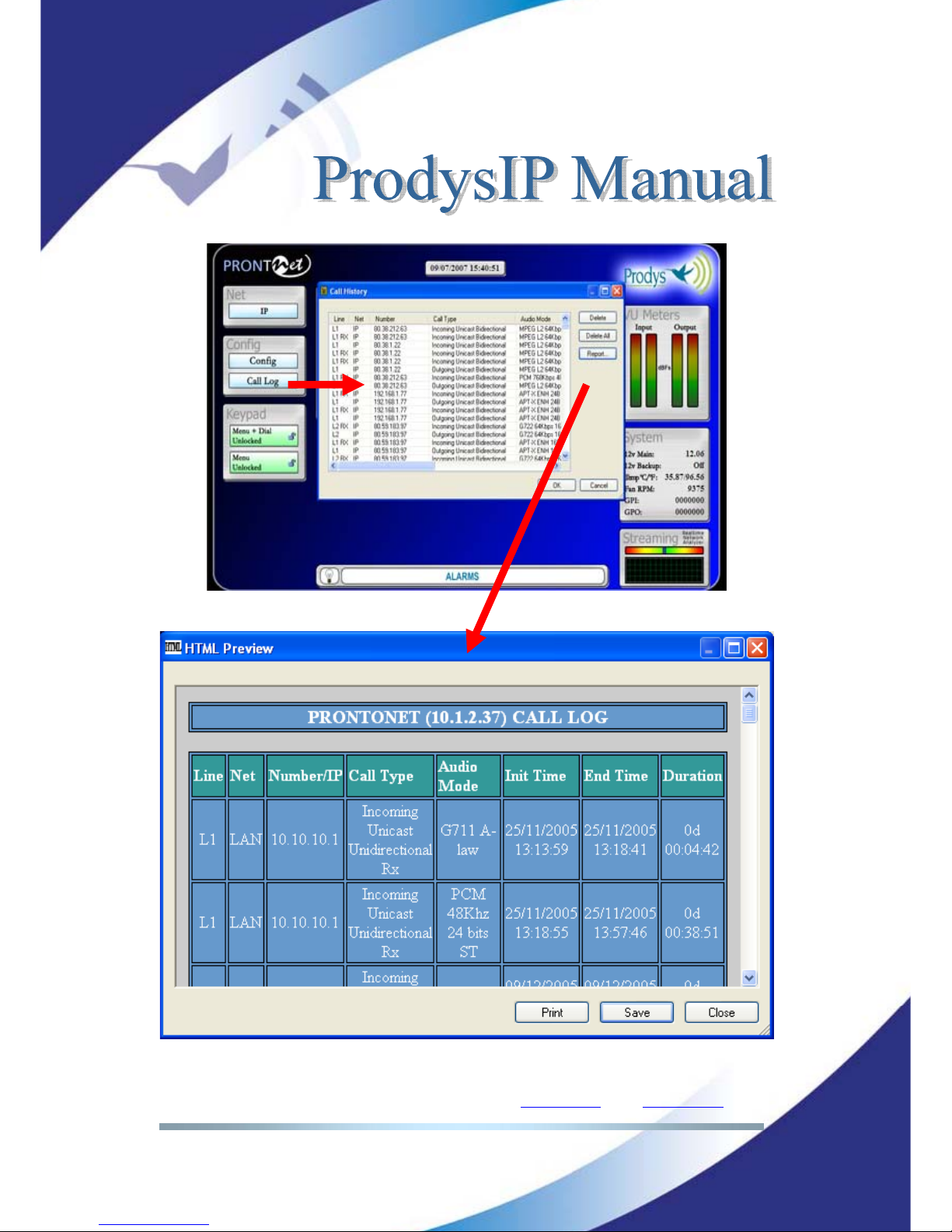
Prodys S.L. Tel: +34 91 6896880 Θ Fax: +34 91 6943777 Θ Email: [email protected] Θ Web: www.prodys.com
Page 77
Page 78
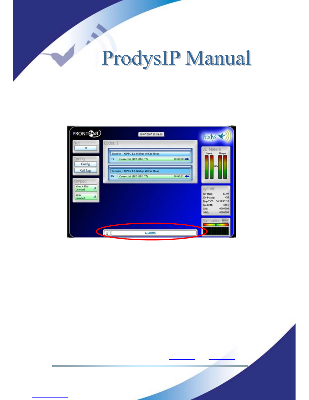
Prodys S.L. Tel: +34 91 6896880 Θ Fax: +34 91 6943777 Θ Email: [email protected] Θ Web: www.prodys.com
Page 78
IV.8 Alarms
The alarm window allows the user to select the alarms that the unit will check.
The unit will notify the occurrence of each of the selected alarms. It is possible
to configure the unit to send SNMP traps or emails to notify alarms information.
See chapter IV.2.5 Alarm Paging.
IV.8.1 Selecting Alarms
The unit allows many different alarms. The selection menu is opened by clicking
over the Alarm area.
Page 79
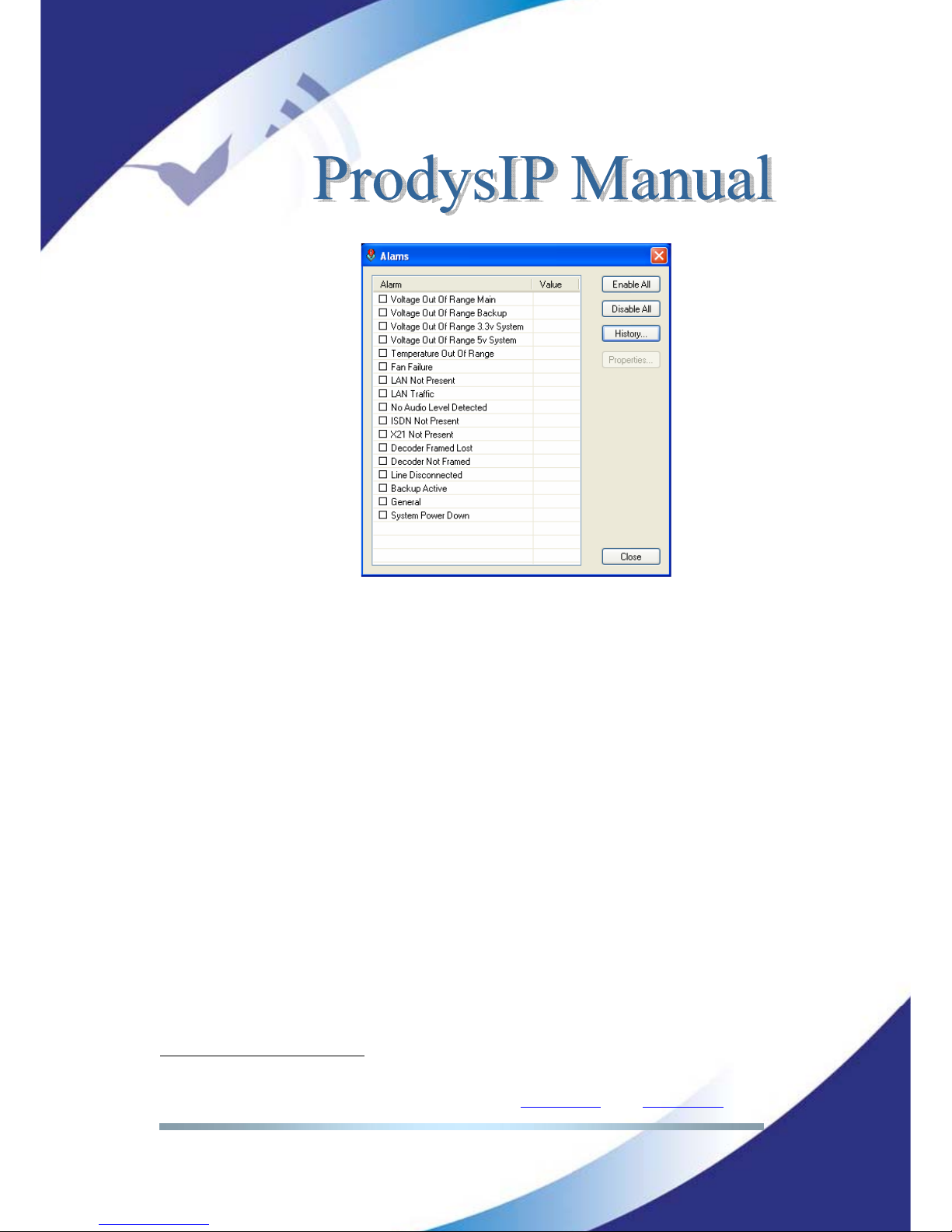
Prodys S.L. Tel: +34 91 6896880 Θ Fax: +34 91 6943777 Θ Email: [email protected] Θ Web: www.prodys.com
Page 79
Voltage Out of Range 12 v Main: The voltage from the main power supply
(AC/DC) is out of range.
Voltage Out of Range 12 v Backup: The voltage from the backup power
supply is out of range.
Voltage Out of Range 3.3 v System: The voltage from the 3.3 DC/DC
converter is out of range.
Voltage Out of Range 5 v System: The voltage from the 5 DC/DC
converter is out of range.
Temperature Out of Range: The temperature is out of range
13
.
Fan Failure: The fun is activated if the internal temperature is over 34º. The
Fan Failure alarm will be activated if the fun doesn’t work when the
temperature is over this threshold.
LAN NOT Present: Not physical level detected in the LAN port.
LAN Traffic: The LAN traffic is higher than the 90% of the capacity of the
network.
No Audio input level detected: No audio is present on the input. A
threshold and a time period can be defined to activate the alarm.
ISDN NOT Present: Not physical level detected in the ISDN port.
X21 Line Not Present: Not physical level detected in the X21 port.
Decoder 1/2 Framed Lost: The Line is connected but the decoder is not
framed anymore. The alarm will be activated also if the unit is turned off. In
13
The temperature is above 50ºC.
Page 80
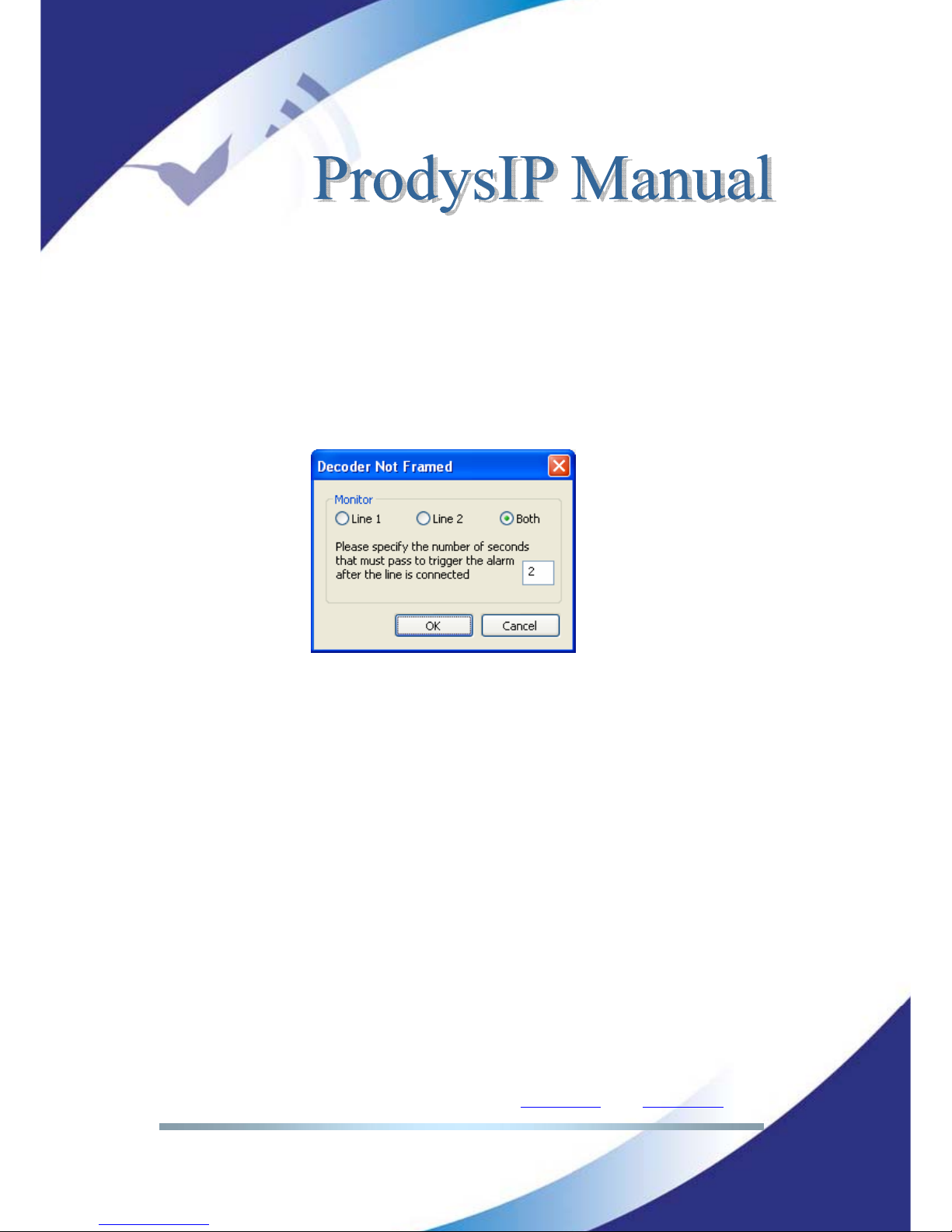
Prodys S.L. Tel: +34 91 6896880 Θ Fax: +34 91 6943777 Θ Email: [email protected] Θ Web: www.prodys.com
Page 80
this case, the alarm will indicate the date and time when the decoder lost the
synchronization, that is, when the unit was turned off. The alarm will be
activated until the unit is framed once the line is connected again. If the
connection is not possible, the alarm will be marked as finished.
Decoder 1/2 Not Framed: The Line is connected but the decoder is not
framed. This new alarm doesn’t require that the decoder was framed
previously. For this reason, it is necessary to specify a window time to decide
when the alarm will be activated once that the NOT FRAMED condition has
been detected.
Otherwise, the alarm would come up as soon as the connection is
established, given that the Decoder needs some time to detect the incoming
compression mode.
Line Disconnected: Line 1/2 has been disconnected unexpectedly,
manually disconnected or both.
Backup Active: The ISDN backup line is working.
General: In internal hardware error was detected by the software.
System Power Down: This new alarm allows the user to know if the unit
was turn off and the time that it remained in that condition.
Page 81
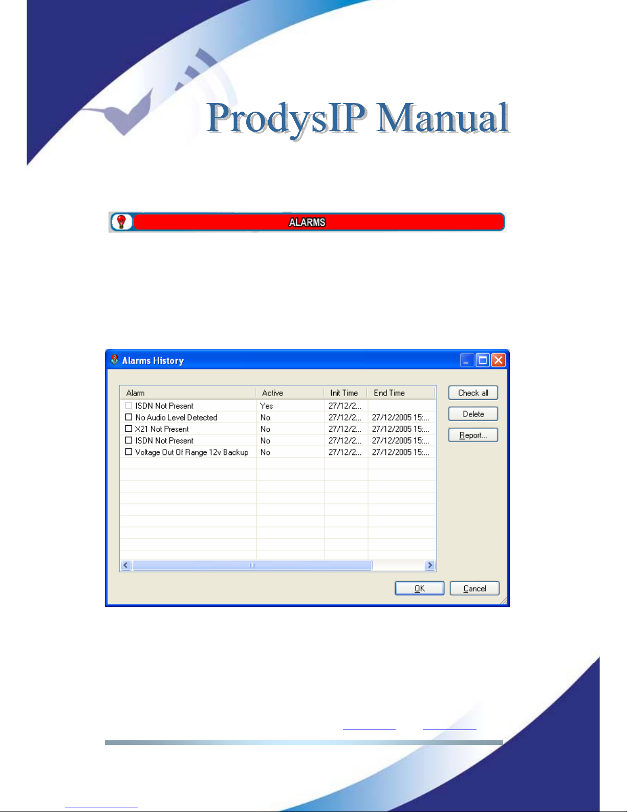
Prodys S.L. Tel: +34 91 6896880 Θ Fax: +34 91 6943777 Θ Email: [email protected] Θ Web: www.prodys.com
Page 81
IV.8.2 Monitoring Alarms
When one of the selected alarms is detected, the alarms window is highlighted.
IV.8.2.1. Alarms History
Alarms are saved on the non volatile memory of the Prodys IP Family codec.
Therefore, it is possible to know what happened in the past even if the unit was
disconnected of the network. The alarms history can be showed by clicking over
the lamp or over “History” option in the alarm selection dialogue.
An historical report of alarms in html allowing preview and print is available.
Page 82
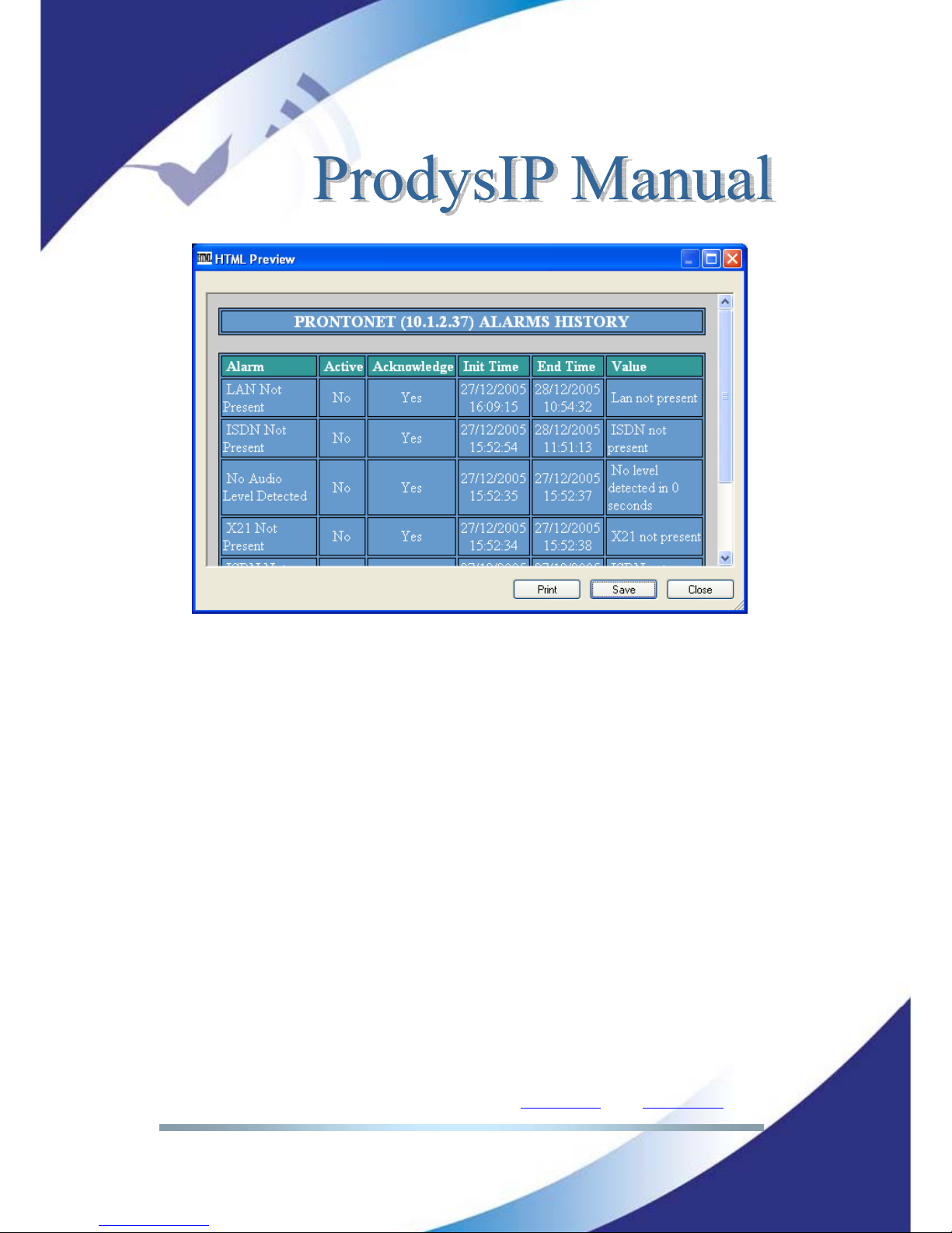
Prodys S.L. Tel: +34 91 6896880 Θ Fax: +34 91 6943777 Θ Email: [email protected] Θ Web: www.prodys.com
Page 82
Page 83
Prodys S.L. Tel: +34 91 6896880 Θ Fax: +34 91 6943777 Θ Email: [email protected] Θ Web: www.prodys.com
Page 83
HOW DOES PRODYS IP FAMILY OF CODECS WORK?
Given the different nature of the three communication standards that the Prodys
IP Family codec supports, the device requires network specific settings for
matching the transmission media. What is more, in situations, Prodys IP Family
codec is capable of dealing with two independent communications at the same
time. This chapter is a practical guide to help in understanding just how the
Prodys IP Family codec unit works under different configurations, in particular
the non conventional ones.
V.1 Selecting the network interface
Firstly, when we refer to the ‘network interface’ we are always referring to the
communications port that is used for the transmission of ‘audio data’. The NET
option from the top menu is applicable for this selection. There are three
settings available for the Prodys IP Family codec:
Prodys IP Family codec operating as “IP CODEC”: The codec will be
configured to establish communications via the Ethernet port using the
IP protocol.
Prodys IP Family codec operating as “ISDN CODEC”: The codec will be
configured to establish communications via a basic access ISDN
connection. The Prodys IP Family codec has a multi-protocol ISDN
terminal socket ready for connection to a basic rate 2B+D interface.
Prodys IP Family codec operating as “X21 CODEC”: The codec can be
configured to establish communications via dedicated digital lines at
64, 128, 192, 256, 384 and 576 Kbps.
Chapter V
Page 84
Prodys S.L. Tel: +34 91 6896880 Θ Fax: +34 91 6943777 Θ Email: [email protected] Θ Web: www.prodys.com
Page 84
Prodys IP Family codec operating as “PSTN CODEC”14: The codec will
be configured to establish communications via any PSTN network.
The Ethernet interface is always available for remote control of the unit, even
if it is configured to operate as an ISDN, PSTN or X21 codec.
You should first select the network type - i.e. the network interface - to be used
for audio data transmission and reception. The menu will only show the
configuration options relevant to the network type selected. Of course, there are
a number of general parameters that will be the same across all network types
and so will not be affected when the network type is changed.
V.2 Configuration parameters that are dependant on the network
type selected
There are two fundamental reasons for which the user must change the Prodys
IP Family codec configuration parameters when a new network interface is
selected:
The available bandwidth over the selected network (IP, ISDN, PSTN or X21).
This places limitations on the bit-rate that can be selected and the amount of
compression. As an example: over ISDN the bit-rates for any algorithm must
fit into 64 or 128Kbps.
The number of available channels: Number of bidirectional communications
which can be achieved. Note that over ISDN and IP, up to two independent
mono communications can be achieved.
The following table shows what the differences between the various
communications networks regarding Prodys IP Family codec operation:
14
PSTN is only available on NomadaIP.
Page 85
Prodys S.L. Tel: +34 91 6896880 Θ Fax: +34 91 6943777 Θ Email: [email protected] Θ Web: www.prodys.com
Page 85
NET ALGORITHM BIT RATES (Kbps) Nº
CHANNELS
PCM 16 bits @ 48 KHz.
G711 64
G722 64
MPEG1,2 LII 64,128,192,256,384
MPEG1,2 LIII 64,128,192,256
MPEG AAC LC.LD 64,128,192,256,384
MPEG 4 AAC HE 24,32,48,56,64,128
IP
aptX
TM
64,128,192,256,384,576
2 Mono
15
or
1 Stereo
G711 64
G722 64
MPEG1,2 LII 64,128
MPEG1,2 LIII 64,128
MPEG 2,4 AAC LC 64,128
MPEG 4 AAC LD,HE 64,128
ISDN
aptX
TM
64
2 Mono
or
1 Stereo
G722 64
MPEG1,2 LII 64,128,192,256,384
MPEG1,2 LIII 64,128,192,256
MPEG AAC LC,LD 64,128,192,256,384
MPEG 4 AAC HE 24,32,48,56,64,128
X21
aptX
TM
64,128,192,256,384,576
1 Mono
or
1 Stereo
V.3 Prodys IP Family codec working as a “DUAL CODEC” over
ISDN
When we select ISDN as the network interface, it is possible to establish two
totally independent MONO connections for each 64 Kbps B Channel. This means
that for each channel or line of communication (Line 1 or Line 2 as seen by the
Prodys IP Family codec) it is possible to send an audio signal encoded with any
of the available codec algorithms. The menu offers the option to configure
Encoder 1 and Encoder 2 separately. However, the user must remember that in
this mode it is only possible to work with MONO signals on each channel, given
that Prodys IP Family codec has only one stereo audio input and one stereo
15
Over IP, the second MONO communication is fixed to G722.
Page 86
Prodys S.L. Tel: +34 91 6896880 Θ Fax: +34 91 6943777 Θ Email: [email protected] Θ Web: www.prodys.com
Page 86
audio output. To avoid incorrect configuration there are therefore some
restrictions while working with the Prodys IP Family codec as a “DUAL CODEC”:
If Encoder 1 is configured in any mode other than DUAL or STEREO/JSTEREO
the Encoder 2 option is disabled and the Prodys IP Family codec will not work
as a “DUAL CODEC”.
The Encoder 2 is not available also when NET = ISDN and bit rate = 128 Kbps.
Encoder 2 can only be configured to work in MONO.
Further section shows how the Prodys IP Family codec operates as an ISDN
CODEC in detail. Restrictions are listed for the Encoder 1 in DUAL or STEREO
mode, as well as for receiving calls from other units that are working in any of
these modes.
V.4 Prodys IP Family codec working as a “Double CODEC” over
IP
A Prodys IP Family codec is a stereo signal capable codec. However the codec
provides a mean to split one stereo codec into two independent mono codecs.
This option is enabled at the NET menu.
<Simple Codec>: This is the setting by default. Stereo audio signals and
any compression algorithm might be enabled.
<Double Codec>: This setting enables two independent mono codecs.
Following restrictions must be remarked:
d) Only mono signals can be encoded and decoded.
e) PCM and AAC HE streaming is not supported.
f) Apt-X and enhanced Apt-X are supported only at 16kHz
sampling frequency
Page 87
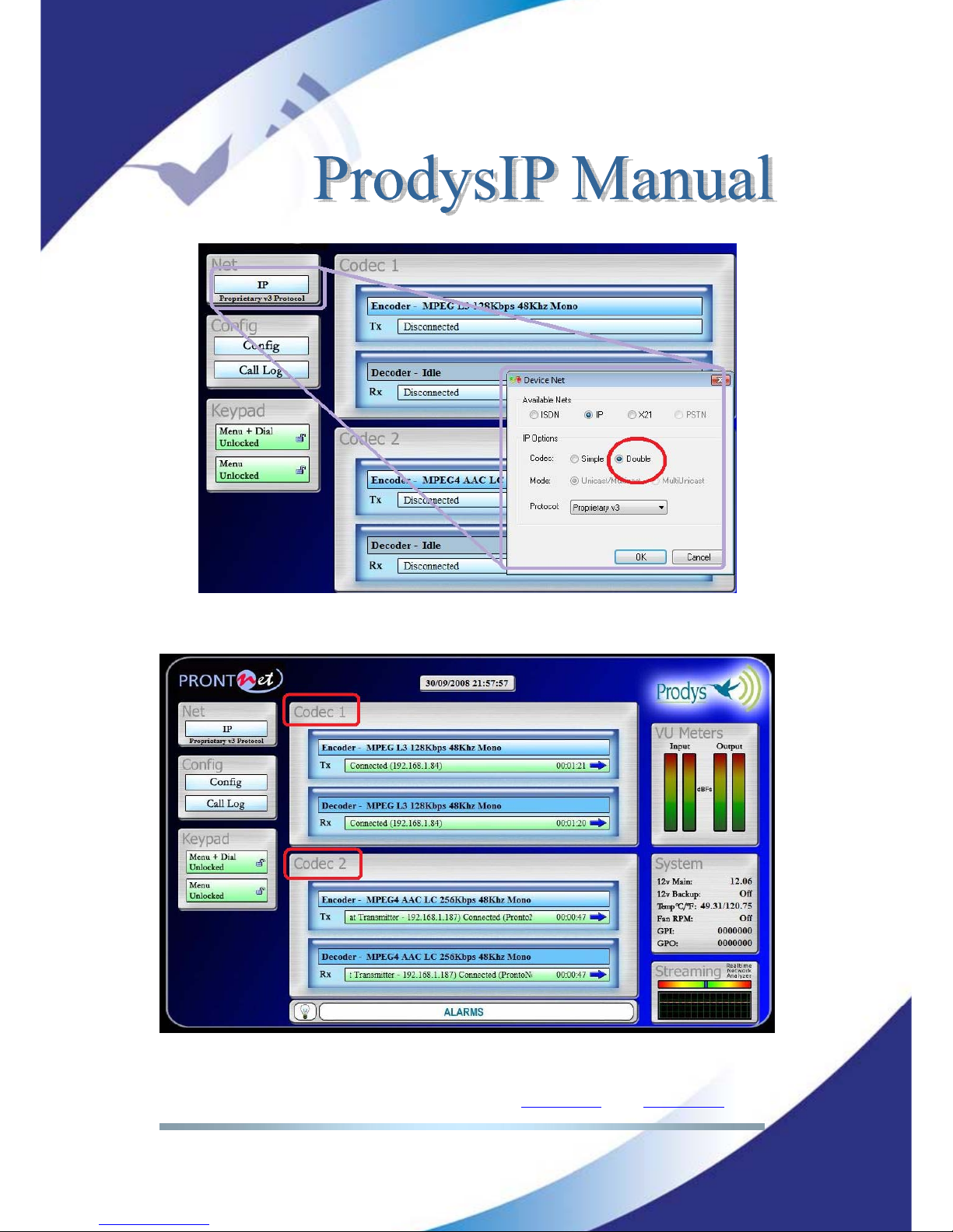
Prodys S.L. Tel: +34 91 6896880 Θ Fax: +34 91 6943777 Θ Email: [email protected] Θ Web: www.prodys.com
Page 87
Page 88
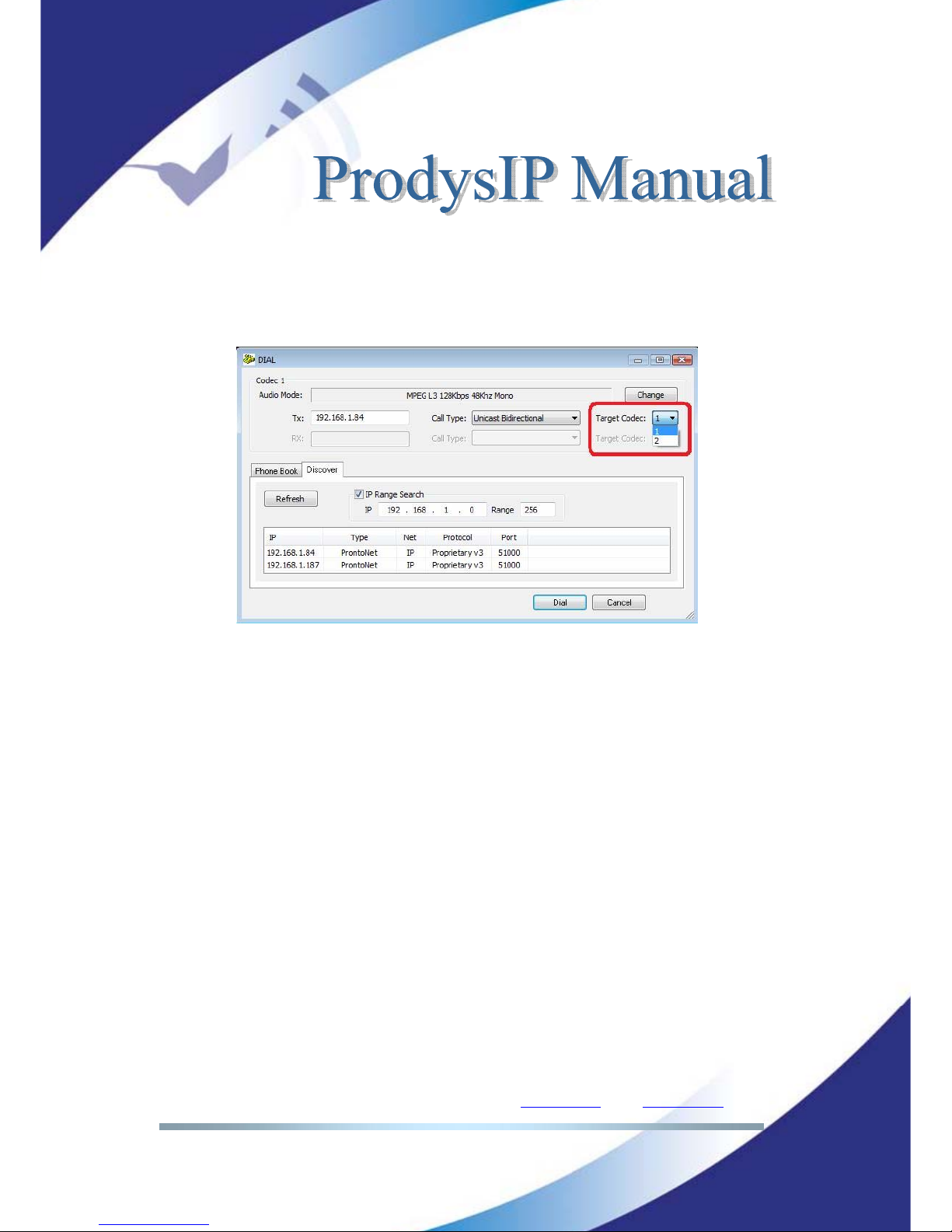
Prodys S.L. Tel: +34 91 6896880 Θ Fax: +34 91 6943777 Θ Email: [email protected] Θ Web: www.prodys.com
Page 88
The <Dial> menu allows selecting the <Target codec>: 1 or 2. This means that
if the far-end codec is also in double mode, the current communication might
address the Codec 2 (the second mono codec) directly.
Page 89
Prodys S.L. Tel: +34 91 6896880 Θ Fax: +34 91 6943777 Θ Email: [email protected] Θ Web: www.prodys.com
Page 89
V.5 About how the Decoder works and automatic searching
The Prodys IP Family codec Decoder system does not require to be configured
by the user; detection of the incoming audio stream parameters is automatic
(given the NET and the Protocol settings matches). However, it is helpful to
highlight some of the logic behind of the automatic operation. The Prodys IP
Family codec is able to synchronise automatically to the following algorithms
under the given conditions:
Algorithm
IP Codec
(NET = IP)
ISDN Codec
(NET = ISDN)
X21 Codec
(NET = X21)
YES
YES
NO
G711
The system detects
incoming calls such as
voice calls and
configures the Encoder
and Decoder to G711.
Algorithm not available.
YES YES YES
G722
Needs G722 encoded
audio since it is
synchronised by means
of statistical framework.
Automatic detection
is unsuccessful if the
Encoder is
configured to aptX ,
AAC HE or J52.
Needs G722 encoded
audio since it is
synchronised by means
of statistical framework.
Automatic detection
is unsuccessful if the
Encoder is
configured to aptX,
AAC HE or J52.
YES YES YES
MPEG1,2 LII
MPEG1,2 LIII
MPEG2,4 AAC LC
& LD
Detects all modes
excepts if the Encoder
is configured to aptX.
Automatic detection
is unsuccessful if the
Encoder is
configured to aptX,
AAC HE or J52.
Detects all modes
excepts if the Encoder
is configured to aptX.
Automatic detection
is unsuccessful if the
Encoder is
configured to aptX,
AAC HE or J52.
YES NO NO
MPEG AAC HE &
aptX
TM
AptX not with
SIP/SAP as IP
protocols
It is necessary that the
Encoder is also set for
the proper algorithm
It is necessary that the
Encoder is also set for
the proper algorithm
PCM
YES NO NO
Page 90
Prodys S.L. Tel: +34 91 6896880 Θ Fax: +34 91 6943777 Θ Email: [email protected] Θ Web: www.prodys.com
Page 90
Linear Audio
Not Available. Not Available.
Taking into account previous table the user must also bear in mind the following:
1. Over X21 or ISDN, it is only possible to set encoding and decoding algorithms
independently for those algorithms that supports automatic synchronising.
For example, it is possible to transmit on G722 and receive on MPEG Layer II.
Although G711 is detected automatically in ISDN mode, the Encoder is also
configured automatically because it is not possible to use it in any other
combination.
2. If we want to receive an algorithm that does not support automatic
synchronisation it is necessary to configure the Encoder to the same
algorithm. In the case of apt-X or Mpeg4 AAC HE, the compression
parameters on the Encoder should match those on the Decoder.
3. If we want the Encoder to switch to the algorithm detected by the Decoder,
the Encoder should simply be set to AUTO mode.
AUTO does not work with those algorithms that do not support automatic
synchronization.
Page 91
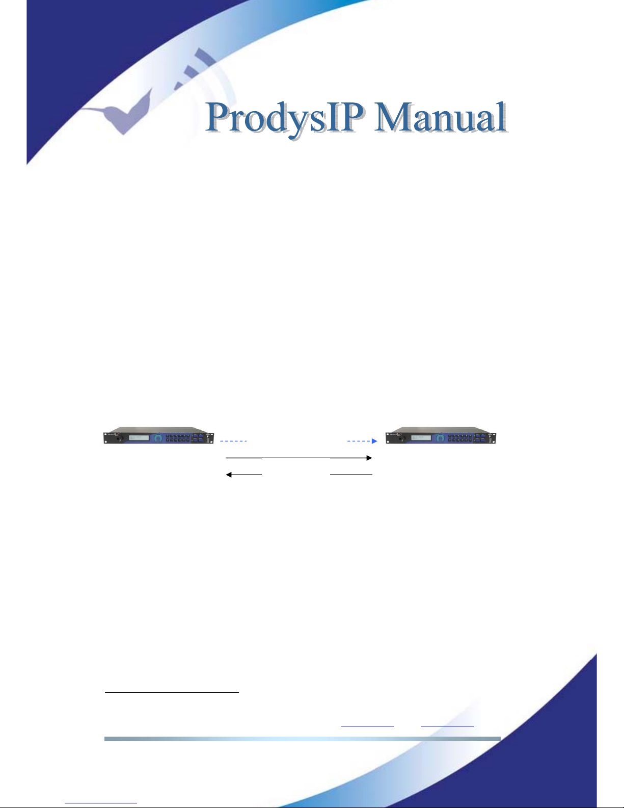
Prodys S.L. Tel: +34 91 6896880 Θ Fax: +34 91 6943777 Θ Email: [email protected] Θ Web: www.prodys.com
Page 91
V.6 The Prodys codec operating over IP (Prodys Proprietary
Protocols)
The operation of the Prodys IP Family codec over IP offers three operational
modes: UNICAST, MULTICAST and MULTIUNICAST
16
.
V.6.1 UNICAST communications
The term UNICAST is used in the networking world to refer to the connection to
a single destination. Unidirectional or bidirectional audio streaming is possible
with this mode.
UNICAST is the default mode and is available for any IP protocol, but for SAP.
Given is an example for Prodys Proprietary Protocol flow-control:
V.6.2 MULTICAST communication
The MULTICAST mode stands for point-to-multi-point communications. This is
one transmitter streams audio towards one or several receivers
In order to start a MULTICAST communication, the connection must be
requested from both ends (transmitter and receivers). Any participant, the
transmitter of the audio stream and all the receivers of the stream must join to
the multicast group. It does not matter which participants joins first. Of course
the actual audio stream will be not available for decoding before the transmitters
joins to the multicast group; up to the audio availability any receiver will just
keep the audio outputs muted.
16
MULTIUNICAST is available from version 5.2.1 onwards.
Prodys IP
Family codec
Prodys IP
Family codec
Calling to 192.168.0.2
Audio P-RTP
Page 92
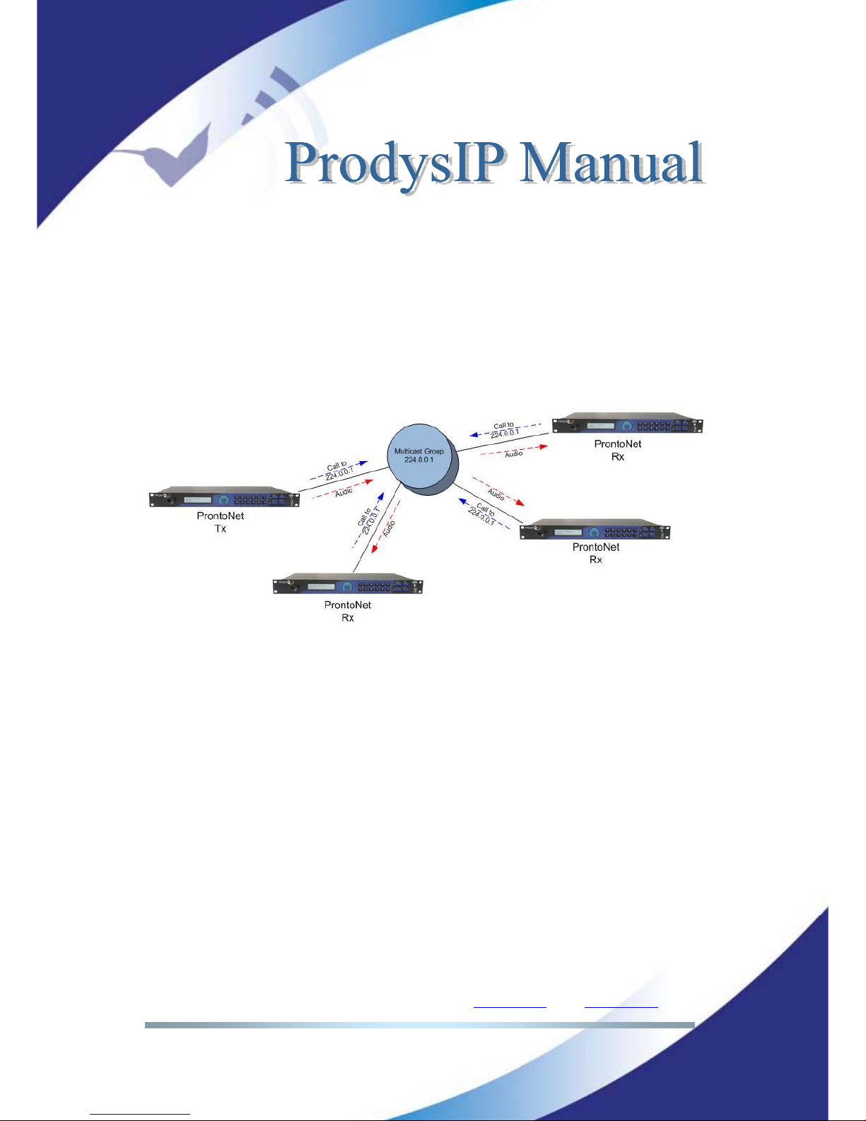
Prodys S.L. Tel: +34 91 6896880 Θ Fax: +34 91 6943777 Θ Email: [email protected] Θ Web: www.prodys.com
Page 92
It is noted that a multicast group is defined by the IP address, which must be
any address included in the 224.0.0.0 /4 range.
The request to join to a multicast group is performed just entering the multicast
IP address into the dial menu of Encoder or Decoder (according whether the
audio stream must be streamed out from or decoded on this codec).
The multicast operation can be shown in the following diagram:
Multicast considerations:
Internet Protocol (IP) multicast is a bandwidth-conserving
technology that reduces traffic by simultaneously delivering a single
stream of information to thousands of corporate recipients and
homes.
Multicast is based on the concept of a group. An arbitrary group of
receivers expresses an interest in receiving a particular data
stream. This group does not have any physical or geographical
boundary—the hosts can be located anywhere. Hosts that are
interested in receiving data flowing to a particular group must join
the group using IGMP. All this is done automatically by Prodys IP
Family codec when establishing a connection.
Multicast traffic is rejected by the Internet infrastructure, since
most IP servers on the Internet do not currently support the
multicasting part of the protocol, except when using VPNs, because
Page 93
Prodys S.L. Tel: +34 91 6896880 Θ Fax: +34 91 6943777 Θ Email: [email protected] Θ Web: www.prodys.com
Page 93
VPN’s encapsulates IP packets as unicast frames, so routers simply
see an ordinary packet.
All IP multicast group addresses will fall in the range of 224.0.0.0
to 239.255.255.255, but some of them are reserved, that’s why the
range of addresses from 224.0.1.0 through 238.255.255.255 are
called globally scoped addresses.
Several transmitters to the same multicast group must be avoided
for preventing of decoding artifacts.
For transmitting MULTICAST audio the Prodys proprietary protocol
“Prodys eXtended Real Time Protocol (PX-RTP) will be used.
The Prodys IP Family codec transmitter cannot be in AUTO mode
for the encoder.
To guarantee a constant delay all the units must synchronise their
clocks. Each receiver will activate a clock-sync algorithm that
adjusts its PLL (Phase-Lock Loop).
Page 94
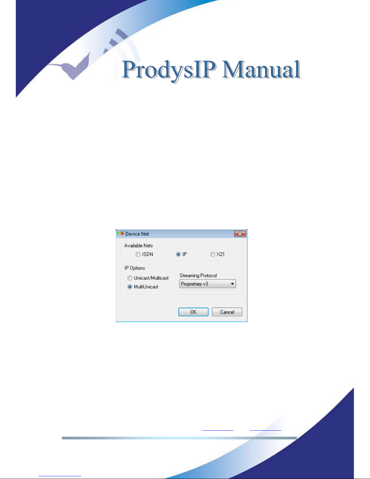
Prodys S.L. Tel: +34 91 6896880 Θ Fax: +34 91 6943777 Θ Email: [email protected] Θ Web: www.prodys.com
Page 94
V.6.3 MULTI-UNICAST
It happens that the MULTICAST mode is not applicable for streaming over the
Internet (section V.6.2). Then MULTI-UNICAST overcomes the lack of Multicast
support on some networks.
This option allows the user to establish point to multi-point connections by
means of many unicast connections. One Prodys IP Family codec can send the
same encoded audio stream up to 10 different destinations.
It has to be remarked that this mode demands multiple streaming bandwidth
over the network and the codec Ethernet interface, since every individual
bandwidth accounts for the total.
This special feature is enabled thru the <NET> menu as the depicted in the
screen shot. Any Prodys Proprietary Protocol is suitable for this purpose.
The main window will show all the available connections:
Page 95
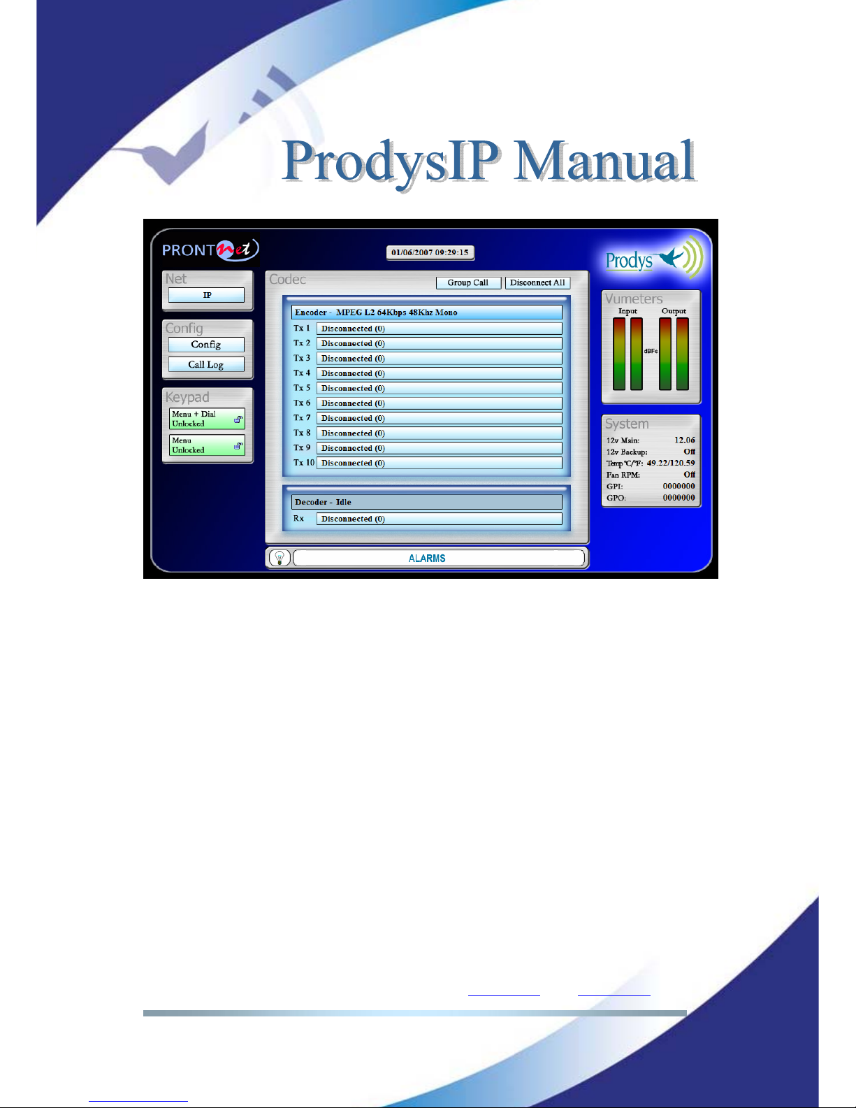
Prodys S.L. Tel: +34 91 6896880 Θ Fax: +34 91 6943777 Θ Email: [email protected] Θ Web: www.prodys.com
Page 95
Depending on the compression mode, up to 10 outgoing connections can be
available:
• MPEG L2, L3 and AAC: Up to 10 Tx + 1 Rx.
• PCM, G711, G722, APTX: Up to 3 Tx + 1 Rx.
The picture displays an independent control box for each connection. Each of the
connection box will show the actual line status. The procedure to establish a call
is the same as that for Unicast connections.
Some remote codecs might drop its communication to the local codec while other
remote codecs keep the current link. In addition, it is possible to make or hang
up several connections at the same time by using the ‘Group Call’ and
‘Disconnect All’ buttons respectively.
As for Unicast connections, the Tx and Rx parts of the connection are divided so
that it is possible to receive from one end at the same time the unit is sending
audio on one or more Tx connections.
Page 96
Prodys S.L. Tel: +34 91 6896880 Θ Fax: +34 91 6943777 Θ Email: [email protected] Θ Web: www.prodys.com
Page 96
This operation mode is incompatible with either <Double IP codec> or <Net
Backup> enabled.
V.6.4 More about Prodys Proprietary Protocols
Prodys has developed this proprietary set of protocols to carry out IP streaming
connections, due to the lack of a standard in this regard:
• Prodys Real Time Control Protocol (P-RTCP): This is a protocol based
on TCP that allows for the establishment and termination of a
connection as well as for the negotiation of the codec mode (automatic
audio synchronisation in all modes).
• Prodys Real Time Protocol (P-RTP): This is a protocol based on UDP
used for the transmission of audio.
• Prodys eXtended Real Time Protocol (PX-RTP). This is a protocol based
on UDP used for the transmission of multicast audio.
• Prodys Upgrading/Identifying Protocol. This protocol is based on UDP
and used to identify/upgrade the units.
• Prodys External Protocol (P-XP). This protocol is based on TCP and can
be used for controlling the units from an application other than the
web page or ProdysControl.
• Prodys Auxiliary Data Protocol (P-AUXP). This protocol is based on UDP
and used for transmitting/receiving auxiliary data.
• Prodys U-bit Protocol (P-UbP). This protocol is based on UDP and used
for transmitting/receiving the User Bit from the AES/EBU frame.
This set of protocols formed the Prodys Proprietary Protocol v1.
V.6.5 More about Prodys Proprietary Protocol v2
This set of protocols is based on the Prodys v1, and it uses the same ports. This
new set of protocols (version 2) is not compatible backward, and it introduces
some new fields in some of the protocols previously listed so that it is
possible to measure lost and disordered packets in real time and during the
audio connection. Proprietary protocol version 1 will allow the user to get
information about jitter and buffer usage, but will not allow the user to obtain
information about lost and disordered packets.
This information will be saved separately for each connection in RAM memory.
Up to 24 hours of data from different calls can be stored.
Page 97
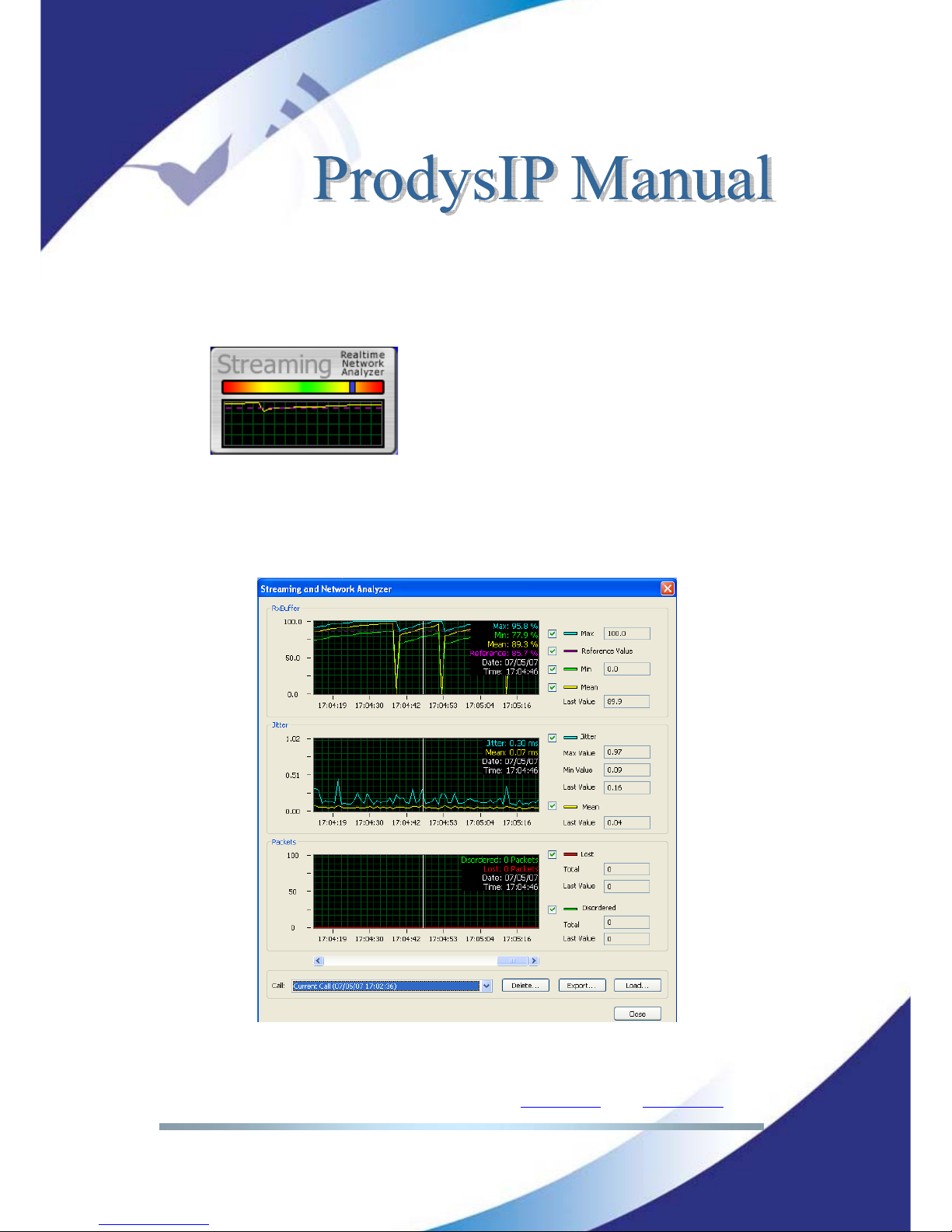
Prodys S.L. Tel: +34 91 6896880 Θ Fax: +34 91 6943777 Θ Email: [email protected] Θ Web: www.prodys.com
Page 97
Once the connection is established, the user can access the ‘real time network
analyzer’ by clicking on the ‘buffer occupation graph’, in order to get information
related to:
-Rx occupation: With average, maximum and minimum usage. Very low
percentage of buffer occupation will cause audio interruptions.
-Jitter: High jitter values will match with low buffer occupation.
-Lost and disordered packets.
All the information is displayed in different graphs, synchronized to each other,
so that the user can move through all the data very easily.
Page 98
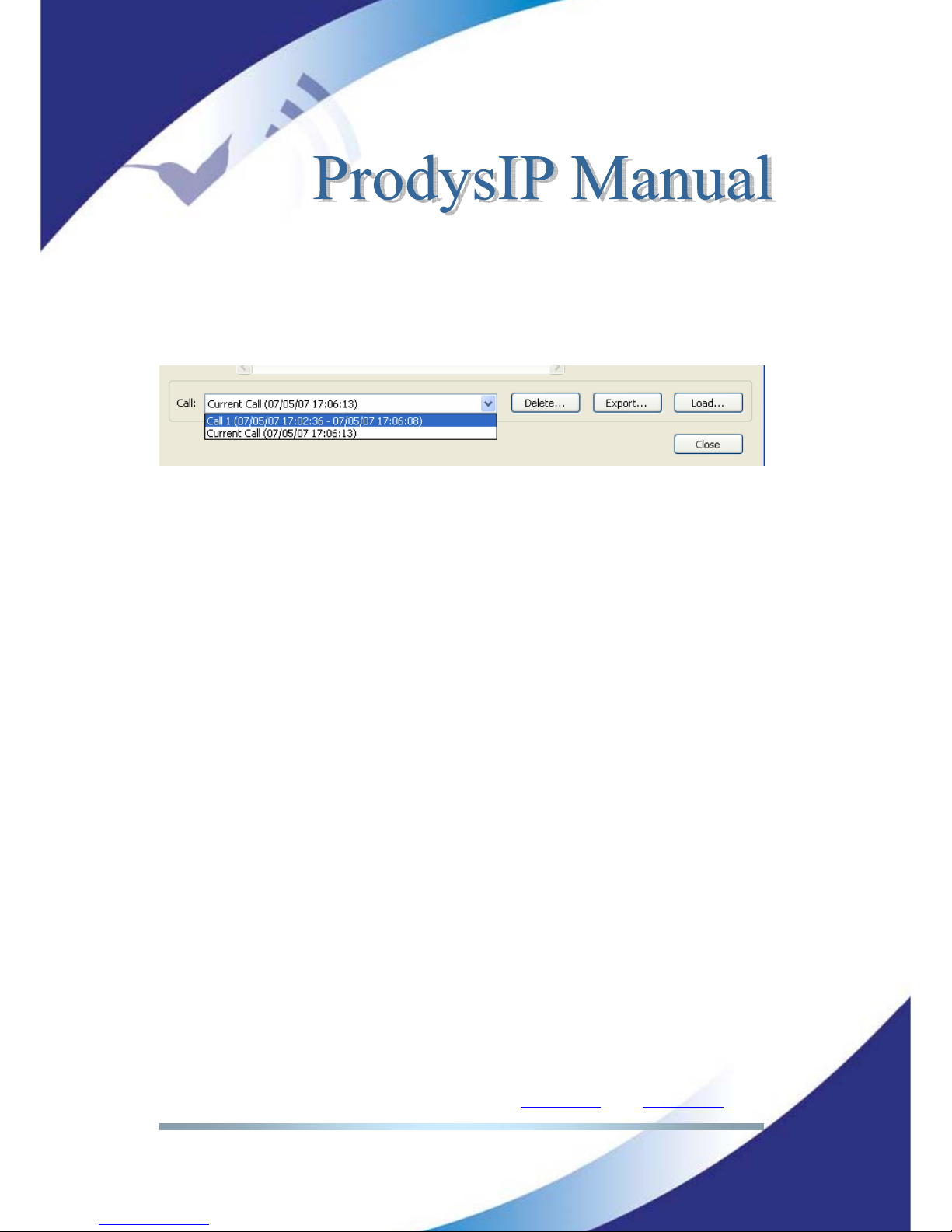
Prodys S.L. Tel: +34 91 6896880 Θ Fax: +34 91 6943777 Θ Email: [email protected] Θ Web: www.prodys.com
Page 98
Data from each connection is stored independently so that it is possible to access
data from connections other than the current one. In addition, it is possible to
delete, export or import data from any previous call.
V.6.6 More about Prodys Proprietary Protocol v3
Another set of proprietary protocols (version 3) is available. This new set of
protocols is not compatible backward. This new set of proprietary protocols
(version 3) applies NAT Traversal techniques.
This new protocol multiplexes auxiliary data (RS232+GPI) into the audio stream,
so that it does not need an additional TCP or UDP port for it, reducing the
number of ports in the communications. In addition, this protocol has been
modified so that no configuration at all is necessary in the router at the caller
side: NAT Traversal Protocol. Only at the callee side, the router has to be
configured to allow the incoming call to proceed.
This will make it possible to make calls from anywhere, regardless of whether
there is a router which can be configured by the user or not. This is very useful
for remote broadcasting from hotels, conference rooms or any other public
location which offers a non configurable IP access to the internet, for example.
More information on this protocol can be found on chapter
Page 99
Prodys S.L. Tel: +34 91 6896880 Θ Fax: +34 91 6943777 Θ Email: [email protected] Θ Web: www.prodys.com
Page 99
V.6.7 IP ports for Prodys Proprietary protocols V1 & V2
These are the default ports for Prodys v1 & v2:
HeraFlash &
Prodys Control
(**)17
UDP:50013
Web Page
(**)
TCP 80: HTTP
TCP 50011: Web Page
TCP 50017: ProdysControl
Audio Streaming
TCP 50019: P-RTCP (Control)
UDP 50021: P-RTP Unicast L1
UDP 50023: P-RTP Unicast L2
UDP 50025: PX-RTP Multicast L1
UDP 50027: PX-RTP Multicast L2
UDP 50037: P-AUXP Datos auxiliares
UDP 50039: P-UbP U-BITs
Test Streaming Tool
(**)
TCP 50033
UDP 50033
External Protocol (P-XP)
(**)
TCP 50031: Control Port
TCP 50035: Status Port
17
(**) means common ports for V1, V2 and V3 Proprietary Protocols
Page 100
Prodys S.L. Tel: +34 91 6896880 Θ Fax: +34 91 6943777 Θ Email: [email protected] Θ Web: www.prodys.com
Page 100
V.6.8 IP ports for Prodys Proprietaty protocols V3
These are the default ports:
HeraFlash &
Prodys Control
(**)18
UDP:50013
Web Page
(**)
TCP 80: HTTP
TCP 50011: Web Page
TCP 50017: ProdysControl
Audio Streaming
TCP 51000: P-RTCP (control)
UDP 51000: P-RTP Unicast /Multicast L1 & P-AUXP Aux. Data (Multiplexed)
UDP 51001: P-RTP Unicast /Multicast L2 & P-AUXP Aux. Data (Multiplexed)
Test Streaming Tool
(**)
TCP 50033
UDP 50033
External Protocol (P-XP)
(**)
TCP 50031: Control Port
TCP 50035: Status Port
18
(**) means common ports for V1, V2 and V3 Proprietary Protocols
 Loading...