

Produits Neptune 3648 User Manual
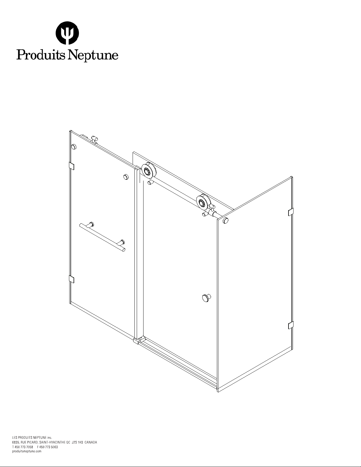
KARMA 3648-3660
INSTALLATION
KARMA 3648 & 3660
10
12
9
11
13
14
22
23
21
15
16
17
18
19
20
27
25
26
8
7
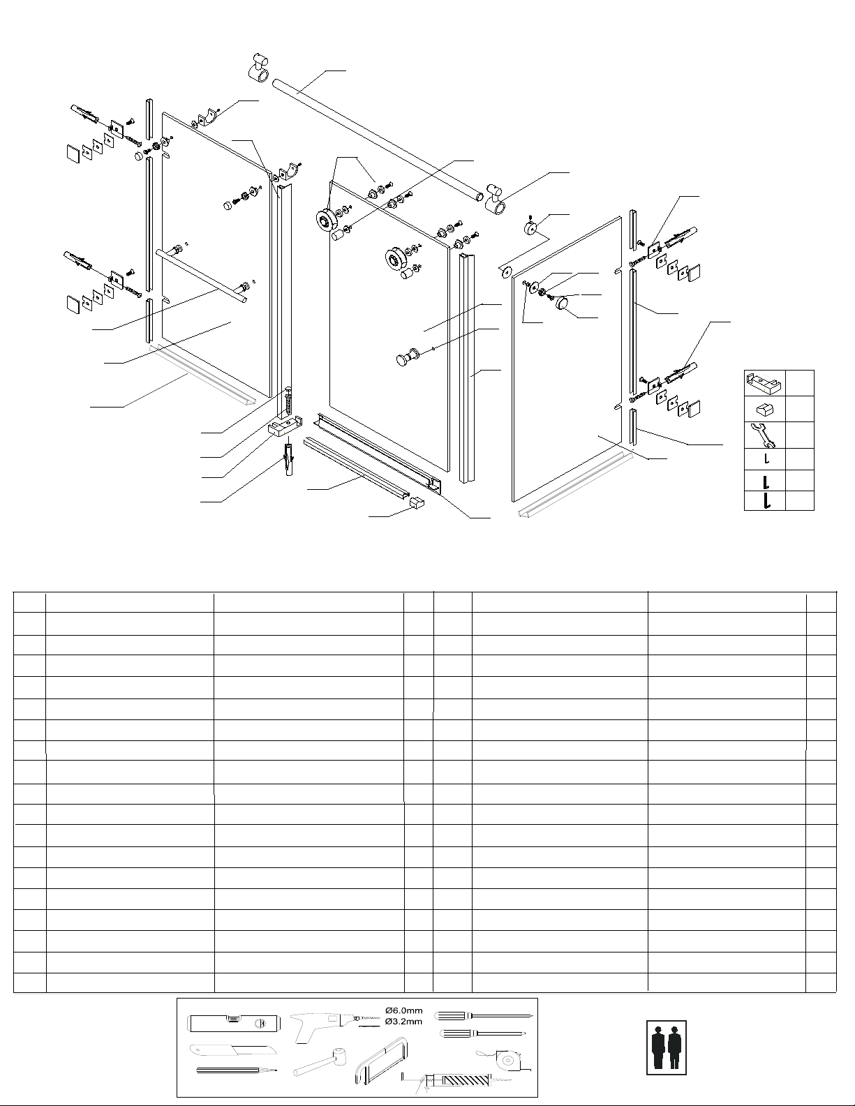
1. Inspect the contents:
• Please verify that all the parts listed on the table have been included in the box.
* In the case of missing parts, contact your distributor immediately.
• It is normal to find surplus parts once the installation is complete.
• The shower base must be perfectly level.
DESCRIPTION
ITEM
1
Threshold cap
Threshold
2
Base plug
3
4
Door guide
5
Screw
6
Screw cap
7
‘’U’‘ channel
8
Fixed panel
9
Towel bar
10
Support tube hook
11
Stainless steel tube
12
Waterproof seal
13
Wheel assembly
14
Blocking cylinder
15
Bumper system
16
Tube support
Washer
17
18
Insert
6
5
4
3
31 1/8'‘ (79.1cm) X 78 3/4'’ (200cm)
23 7/8'‘ (60.6cm) X 78 3/4'’ (200cm)
46'‘ (116.8cm) ou 57 1/2'‘ (146.1cm)
78'‘ (198.4cm)
2
DIMENSION
right
22'' (56cm)
right
ST5X30
24
31
32
28
29
1
QTY
1
1
1
1
1
1
2
1
1
2
1
1
2
2
2
1
1
1
30
ITEM
DESCRIPTION
19
Screw
20
Tube cap
21
Washer
22
Door panel
23
Handle
24
Waterproof door seal
25
Wall support bracket
26
Wall plug
‘‘U’’ channel
27
‘‘U’‘ channel
28
Fixed return panel
29
Door swipe
30
31
Door guide
32
Threshold cap
33
Plastic wrench
Allen key
34
Allen key
35
Allen key
36
DIMENSION
M8X20
31 1/8‘‘ (79.1cm) X 78 1/4'’ (198.8cm)
25 3/4‘‘ (65.4cm) X 78 1/4'’ (198.8cm)
78 1/4'‘ (198.8cm)
58 7/8'‘ (149.6cm)
8 1/4'‘ (20.8cm)
34 3/8‘‘ (87.6cm) X 78 3/4'’ (200cm)
26 5/8'‘ (67.6cm) ou 31 3/4'‘ (79.4cm)
left
left
3mm
4mm
5mm
33
34
35
36
QTY
1
1
1
1
1
1
4
4
2
4
1
1
1
1
1
1
1
1
2 People
INSTALLATION
General information
Read the installation guide and warranty carefully and completely before proceeding or opening any hardware contents.
This shower door should be installed by a recommended professional installer.
Wear safety glasses, gloves and appropriate protective wear at all times during installation.
Verify that you have all the necessary tools and accessories as shown on page 2.
It is imperative to have a second person assisting on all steps of the
installation for safety and ease of installation.
All dimensions shown are nominal.
NEVER allow the glass panel to come into contact with any other hard surface (tile, stone, ceramic, etc.),
as it risks chipping or breakage.
Handle with care at all times.
Remove the protective poly-film from the flood rim before beginning the
installation of your door.
The designs in this guide are shown as right side installation, for a left
side installation mirror the images.
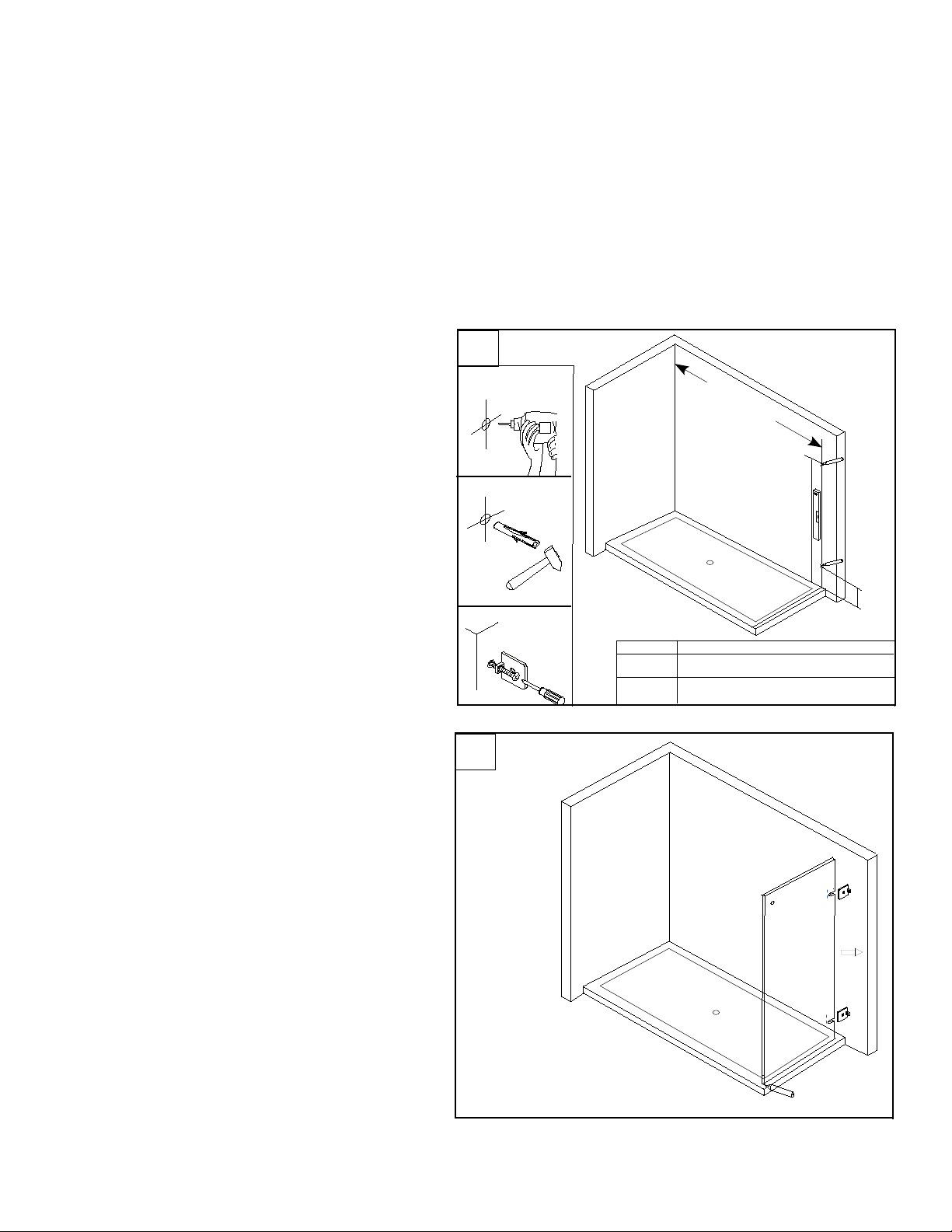
Step1 Wall support installation
Draw a vertical line on the wall (Figure 1), centered on the
flood rim, while respecting the minimum and maximum seen
on the table below figure 1 and extend line on the base, parallel to the rim.
Mark the locations for the screw holes on the wall at 9'‘ and 69
11/16'’ from the flood rim along the line.
Drill the holes with the appropriate drill bit and insert the wall
plugs.
Next attach the wall support brackets always checking their
alignment.
Step 2 ‘’U’‘ channel installation on fixed return panel
Clean thoroughly the base and the wall for dust and grease
before installing the “U” channels.
Temporarily install the fixed return panel #29 being careful
not to damage the base and verify that the panel meets the
base and the wall correctly.
Mark reference points on the flood rim where the fixed
panels end. (Figure 2)
Remove the fixed glass panel and place it securely aside.
1
°6.0mm
2
Model
3648
3660
min. - max.
69 11/16'‘
9'‘
min. - max.
46 1/4"(117.5cm) - 47 5/8"(121cm)
57 5/8"(146.4cm) - 59"(149.9cm)
 Loading...