

Page 1
PCS 3000
Ultra Flow Controller
Quick Reference Guide
Mode
4
S
P
L
U
N
G
E
R
L
I
F
T
E
Q
U
I
P
M
E
N
T
M
F
R
.
Production Control Services, Inc.
Page 2

1
PCS 3000
ULTRA FLOW
PCS 3000 Ultra Flow Controller
Quick Reference Guide
Contents
Installation Instructions . . . . . . . . . . . . . . . . . . . . . . . . . . . . . . . . . . . . . . . . . . . . . . . . . . . . . . . . . . . . . 2
Circuit Board Wiring . . . . . . . . . . . . . . . . . . . . . . . . . . . . . . . . . . . . . . . . . . . . . . . . . . . . . . . . . . . . . . . 3
Turning the Controller On and Off . . . . . . . . . . . . . . . . . . . . . . . . . . . . . . . . . . . . . . . . . . . . . . . . . . . . 3
Using the Buttons . . . . . . . . . . . . . . . . . . . . . . . . . . . . . . . . . . . . . . . . . . . . . . . . . . . . . . . . . . . . . . . . . 4
Reading the Controller Reports . . . . . . . . . . . . . . . . . . . . . . . . . . . . . . . . . . . . . . . . . . . . . . . . . . . . . . . 4
Clearing Report Values . . . . . . . . . . . . . . . . . . . . . . . . . . . . . . . . . . . . . . . . . . . . . . . . . . . . . . . . . . . . . 5
How Pressure Operation Works . . . . . . . . . . . . . . . . . . . . . . . . . . . . . . . . . . . . . . . . . . . . . . . . . . . . . . 6
Calibrating the Transducers . . . . . . . . . . . . . . . . . . . . . . . . . . . . . . . . . . . . . . . . . . . . . . . . . . . . . . . . . . 7
Creating a Pressure-Operation Plunger Program . . . . . . . . . . . . . . . . . . . . . . . . . . . . . . . . . . . . . . . . . . 7
Intermitting a Well with Pressure Operation . . . . . . . . . . . . . . . . . . . . . . . . . . . . . . . . . . . . . . . . . . . . 11
Programming All Functions . . . . . . . . . . . . . . . . . . . . . . . . . . . . . . . . . . . . . . . . . . . . . . . . . . . . . . . . . 12
Troubleshooting . . . . . . . . . . . . . . . . . . . . . . . . . . . . . . . . . . . . . . . . . . . . . . . . . . . . . . . . . . . . . . . . . 13
Equipment Checks . . . . . . . . . . . . . . . . . . . . . . . . . . . . . . . . . . . . . . . . . . . . . . . . . . . . . . . . . . . . . . . 15
Specifications . . . . . . . . . . . . . . . . . . . . . . . . . . . . . . . . . . . . . . . . . . . . . . . . . . . . . . . . . . . . . . . . . . . 16
Mode
4
S
Page 3
P
L
U
N
G
E
R
L
I
F
T
E
Q
U
I
P
M
E
N
T
M
F
R
.
2
Quick Reference Guide: Mode 4
PCS 3000
ULTRA FLOW
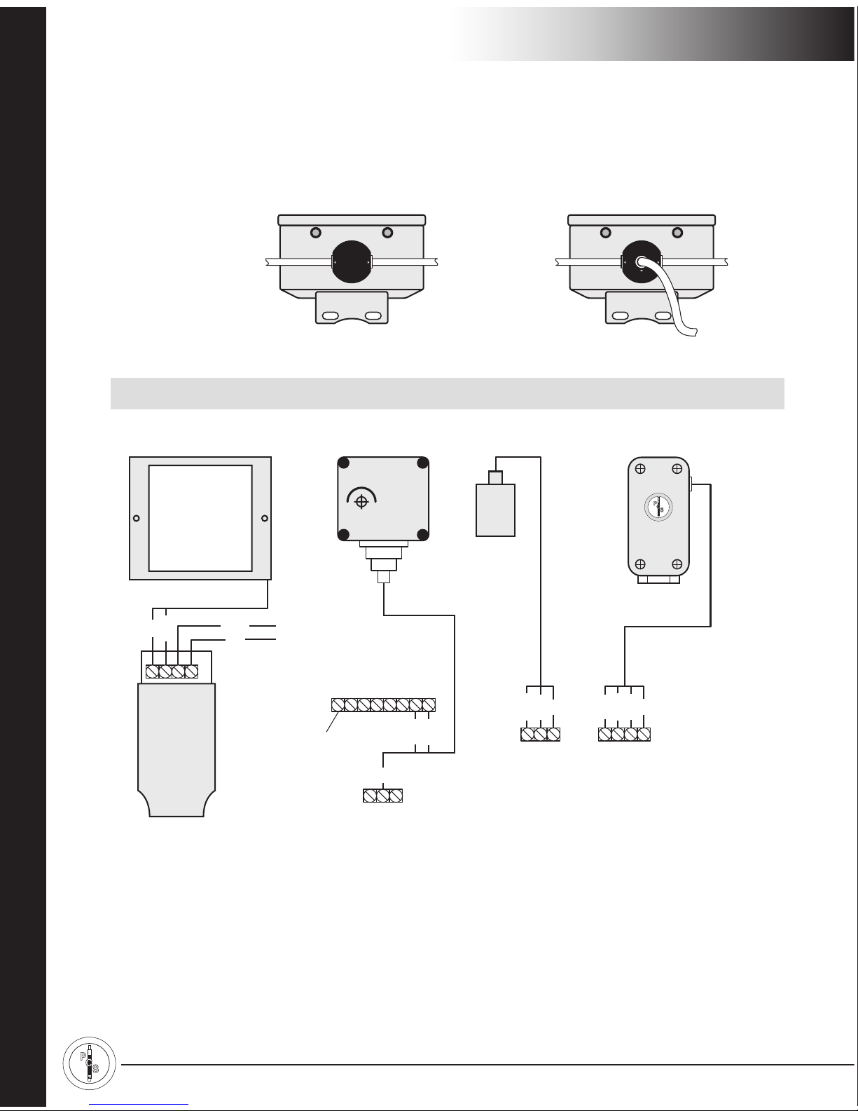
Installation Instructions
CAUTION! Turn off the controller before you connect or disconnect any wires.
Figure 1 –Installation Instructions
TransducersSolar Panel Arrival Sensor A-Valve
Supply Gas &
Motor-Valve
Output
Hookup
Terminal block
on faceplate
A-valve is wired to terminals
on main circuit board.
(Remove faceplate.)
B-valve is wired to B OPEN,
B COM, and B CLOSE.
(Optional C-valve is wired to
C OPEN, C COM, C CLOSE.)
Pressure Connectors:
• 1/4" NPT for supply
and output
• 35-50 PSI
Wiring
1. Remove faceplate.
2. Wire sensor’s red (+) 6-volt
battery wire to BAT+ terminal
on main circuit board.
Supply
B-Valve
Single-Valve Controller
Controller Bottom View
Supply
Output
to A-Valve
A-Valve B-Valve
Supply
Dual-Valve Controller
Controller Bottom View
Output to
A-Valve
Output to
B-Valve
Supply
T PWR
TRAN+
TRAN–
GND
red
green
white
black
1. Remove faceplate.
2. Wire each transducer
to terminals on circuit
board. (See instructions
inside faceplate.)
0000 LBS. PSI.
PART# ECP-0342
FT. LUPTON, CO
REMOTE
PRESSURE
TRANSDUCER
A OPEN
A COM
A CLOSE
red
black
green
OPEN
NEG–
AUX
CLOSE
SOLAR+
SOLAR–
SENSOR–
SENSOR IN
black
green
BAT–
BAT+
A OPEN
red
red
black
Panel must face south
P
L
U
N
G
E
R
L
I
F
T
E
Q
U
I
P
M
E
N
T
M
F
R
.
+
+
+
+
+SOL- -BAT+
black
red
Solar panel is wired
to Patch PCB.
(Remove faceplate.)
Do NOT wire solar
panel to terminal
block on faceplate.
To battery
Page 4
3
Quick Reference Guide: Mode 4
PCS 3000
ULTRA FLOW
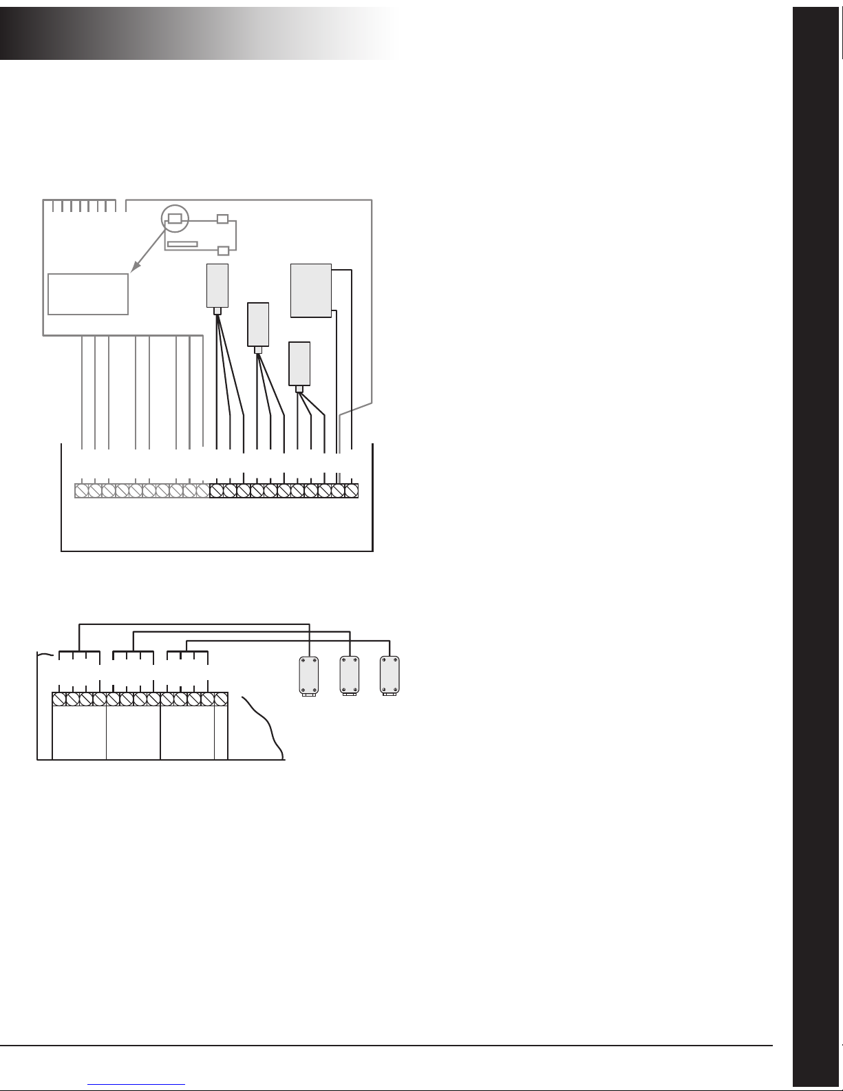
Circuit Board Wiring
CAUTION! Turn off the controller before you connect
or disconnect any wires.
Figure 2 –Terminal Block on Main Circuit Board
Figure 3 –Terminal Block on Surge Protector Board
Turning the Controller On and Off
To turn the PCS 3000 Ultra Flow Controller on or off,
insert a screw driver into the slot marked POWER ON/
OFF. See Figure 4 on page 4.
Move the toggle switch to the left to turn the
controller on. Move the toggle switch to the right to
turn the controller off.
The plunger program does not run while the controller
is off. When you turn the controller on, it closes the
A-valve and starts counting down the OPEN time
DELAY (see step 1 on page 6).
Reading Reports and Functions
1Press READ.
This screen appears: SELECT PARAMETER
READ: 00
2 Enter report or function parameter. Example: 10.
Programming Functions
1Press SET.
This screen appears: SELECT PARAMETER
SET: 00
2 Enter function parameter. Example: 05.
3 Enter value for function. Time is in hours:minutes:
seconds. Pressure is in pounds per square inch (psi).
To exit function without changing its value,
press CE.
T PWR
TRAN 3+
TRAN 3-
T GND
TRAN 2+
TRAN 2-
T PWR
TRAN 1+
TRAN 1-
T GND
orange
green
white
green
white
green
white
black
battery + red
power orange
ground black
tran 3+ green
tran 3- white
tran 2+ green
tran 2- white
tran 1+ green
tran 1- white
To surge
protector
board
To surge protector board
Surge
protector
board
BAT-
BAT+
A OPEN
A COM
A CLOSE
B OPEN
B COM
B CLOSE
C OPEN
C COM
C CLOSE
– +
Battery
TERMINAL
WIRE
COLOR
black
red
red
black
green
red
black
green
red
black
green
C-Valve
B-Valve
A-Valve
FIELD
SENS +
T PWR
TRAN +
TRAN -
GND
T PWR
TRAN +
TRAN -
GND
T PWR
TRAN +
TRAN -
GND
red
green
white
black
red
green
white
black
red
green
white
black
Transducer 1
(casing)
Transducer 3
(line)
Transducer 2
(tubing)
WIRE
COLOR
3
2
1
Page 5
P
L
U
N
G
E
R
L
I
F
T
E
Q
U
I
P
M
E
N
T
M
F
R
.
4
Quick Reference Guide: Mode 4
PCS 3000
ULTRA FLOW
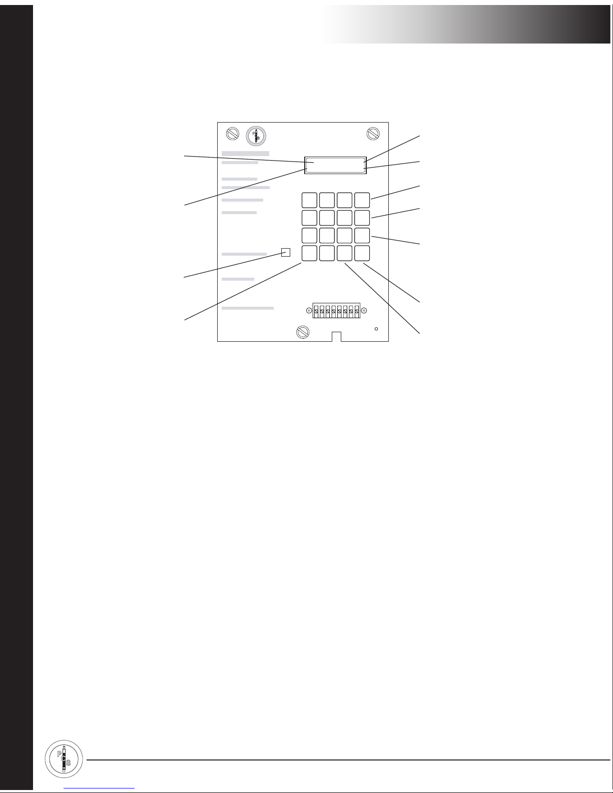
Using the Buttons
Figure 4 –Controller’s Faceplate
Reading the Controller Reports
Plunger Travel Time Reports
READ 06
These 10 reports show the 10 most recent plunger
travel times. PLT-0 shows the most recent plunger run,
PLT-1 shows the second most recent, and PLT-9 shows
the tenth most recent. On these reports:
●
A = plunger surfaced during OPEN time.
●
B = plunger surfaced during B OPEN time.
The time shows how long the plunger took to surface.
For example: PLT-0 A 00:01:15 shows that the
plunger surfaced after 1 minute and 15 seconds of
OPEN time. If the plunger does not surface, this
screen appears: PLT-3 NO PLUNGER.
To display the next report, press READ.
Valve/Plunger Counts and Total Time
Reports
READ 10
This reporting option displays the two Valve and
Plunger Counts Reports (READ 04 and READ B 4) and
the two Total Time Reports (READ 07 and READ B 7).
To display the next report, press READ.
A-Valve and Plunger Counts Report
READ 04
This report shows how many times the A-valve opens,
and how many times the plunger arrives while the
A-valve is open. Example: A PLUNGER = 0092
A VALVE = 0096
In this example, the plunger did not arrive 4 times
while the A-valve was open. If the well has a B-valve,
the plunger may have arrived 4 times while the
B-valve was open. See the next report: “B-Valve and
Plunger Counts Report”.
1 2 3
ON
4 5 6
OFF
7 8 9 B
READ
0
SET CE
POWER
ON/OFF
DISPLAY STATUS HRS:MIN:SEC
HIGH PSI LOW PSI
P. C.S. 3000
PRODUCTION CONTROL SERVICES, INC.
©
FT. LUPTON, COLORADO
Ultra
Flow
OPERATING INSTRUCTIONS
MANUAL VALVE CONTROL
OPEN A - VALVE (SALES)
PRESS
: ON
CLOSE A & B VALVES
PRESS
: OFF
OPEN B - VALVE (VENT)
PRESS
: B - ON
FULL PROGRAM SETTING
PRESS
: SET - 90
TO PROGRAM INDIVIDUAL SETTING
PRESS
: SET
THEN
PRESS
: PARAMETER OR #
TO READ INDIVIDUAL SETTING
PRESS
: READ
THEN
PRESS
: PARAMETER OR #
PARAMETER & NUMBERS
ON = OPEN TIME (HEAD GAS)
OFF = CLOSE TIME
#02 = DELAY TIME (SALES)
#03 = MANDATORY SHUT IN
#04 = A & B VALVE PLUNGER COUNTS
#05 = OPEN TIME DELAY
#08 = DELAY CLOSE TIME
#20 =
CASING DROP (WITHOUT SENSOR)
#21 =
CASING TIME (CASING PSI PEAK)
SHORT SCAN PLUNGER HISTORY
PRESS
: READ
#06 - PLUNGER TRAVEL TIME (LAST 10)
#10 - PLUNGER - VALVE COUNTS & TIMES
#19 - LAST OPEN & CLOSE TIMES
#90 - FULL SCAN OF PROGRAM
PRESSURE OPERATION
#11 = SELECT CONTROLLER MODE
(1-TIMES, 2-CAS DIP)
#12 = OPEN PRESSURE DIFFERENTIAL
#13 = CLOSE CAS DIP INCREASE
#14 = HIGH LINE CLOSE PRESSURE
#15 = LOW LINE CLOSE PRESSURE
B - VALVE FUNCTIONS & PARAMETERS
B - VALVE OPEN TIME
PRESS
: SET - B - ON
A - VALVE W/B-VALVE OPEN
PRESS
: SET - B - 0
B - VALVE DELAY TIME
PRESS
: SET - B - 2
NOTE: CROSSING OR MISPLACING THE
TERMINAL LEADS COULD CAUSE FUSE
TO BLOW OR DAMAGE THE UNIT.
THE PCS 3000 CONTROLLER IS MANUFACTURED BY PCS, INC © 1998
1-800-619-2241
PATENT PENDING
P
L
U
N
G
E
R
L
I
F
T
E
Q
U
I
P
M
E
N
T
M
F
R
.
OPEN
NEG –
AUX
CLOSE
SOLAR+
SOLAR –
SENSOR –
SENSOR IN
Currently running
program function
Time remaining
in hrs.:min.:sec.
Casing
pressure
Line pressure
Opens A-valve
Closes A-valve and
B-valve
Used with other keys
to access functions tha
t
control B-valve.
Example: B ON opens
B-valve
Clears current entry
and backspaces
Sets program function
Reads reports
and function
valves
On/off
switch
CLOSED 00:00:00
C0000 L0000
Page 6

5
Quick Reference Guide: Mode 4
PCS 3000
ULTRA FLOW
B-Valve and Plunger Counts Report
READ B 4
This report shows how many times the B-valve opens,
and how many times the plunger arrives while the
B-valve is open. Example: B PLUNGER = 0004
B VALVE = 0004
A-Valve Total Time Report
READ 07
This report shows 2 times of up to 999 hrs., 59 min.,
59 sec. accumulated since you last cleared the report:
●
Total OPEN time and DELAY time (SALES).
●
Total time that the controller was closed.
MANDATORY SHUT-IN (if any), OPEN time
DELAY (if any), and CLOSE time are accumulated
under TOT CLS time.
Example: A TOTAL016:31:13
TOT CLS008:12:45
B-Valve Total Time Report
READ B 7
This report shows the total amount of B OPEN time
accumulated since you cleared the report, up to 999
hrs., 59 min., 59 sec. Example: B TOTAL001:24:32.
Last Open and Close Reports
READ 19
LST OP (LAST OPEN) – The last time the A-valve was
open, the letter shows why the A-valve closed:
●
P = pressure input
●
S = switch gauge input
●
T = time ran out
The time shows how long the A-valve was last open.
It consists of OPEN time and DELAY time (SALES) –
which includes DELAY CLOSE time, if any. It does not
include B OPEN time, if any.
Example: LST OP T00:20:00
LST CL (LAST CLOSED) – The last time the A-valve
was closed, the letter shows why the A-valve opened:
●
C = casing peak pressure input
●
D = differential open pressure input
●
T = time ran out
The time shows how long the A-valve was last closed.
Example: LST CL D00:15:00
Program Function Reports
READ 90
These reports display the current values of the time
and pressure program functions. For a list, see
“Programming All Functions” on page 12.
Battery Report
READ 00
This report displays BATTERY OK or BATTERY LOW.
Version Report
READ CE
This report displays the chip and software version
numbers, for example: VERSION: 076-03.
Clearing Report Values
SET 10
Press the ON button to clear all of the valve and
plunger counts and total times.
Note: Press the OFF button to exit the Clearing
Report Values function without clearing any of the
report values.
Page 7

P
L
U
N
G
E
R
L
I
F
T
E
Q
U
I
P
M
E
N
T
M
F
R
.
6
Quick Reference Guide: Mode 4
PCS 3000
ULTRA FLOW
How Pressure Operation Works
1 The controller closes the A-valve and counts down
the OPEN time DELAY (SET 05). This gives the
plunger time to fall to the bottom of the well. The
display status shows CLOSED 00:00:00.
Note: CLOSE time is normally set to 00:00:00
because the controller opens the A-valve in
response to changes in pressure. For more
information, see “CLOSE Time” on page 10.
2 While the A-valve is closed, the casing pressure
rises. The controller monitors casing pressure minus
sales line pressure. It opens the A-valve when:
▪
The difference between casing and sales line
pressure is equal to or greater than the
DIFFERENTIAL OPEN PRESSURE (SET 12)
value, and
▪
The OPEN time DELAY countdown has reached
zero.
Go to step 3.
If the DIFFERENTIAL OPEN PRESSURE value is
reached during the OPEN time DELAY countdown,
the display status shows the OPEN time DELAY
remaining.
Note: To open the well when the casing pressure
peaks (instead of using the DIFFERENTIAL OPEN
PRESSURE), see “CASING PEAK Time and CASING
RISE PRESSURE” on page 10.
3 The controller opens the A-valve and counts down
the OPEN time (SET ON).
▪
If the plunger arrives during the OPEN time
countdown, the controller goes to step 5.
▪
If the plunger does not arrive during the OPEN
time countdown, the controller goes to step 4.
4 The controller opens the optional B-valve and
counts down the B OPEN time (SET B ON).
▪
If the plunger arrives during the B OPEN time
countdown, the controller goes to step 5.
▪
If the plunger does not arrive during either
OPEN time or B OPEN time, the controller
closes the A-valve and B-valve and counts
down the MANDATORY SHUT-IN time
(SET 03). When this countdown reaches zero,
the controller opens the A-valve. Go to step 3.
Note: If the well has liquid trailing behind the
plunger, you may want to set B DELAY time. See
“B DELAY Time” on page 11 for more information.
5 The controller monitors the casing pressure for a
minimum value and counts down the DELAY time
(SALES) – SET 02.
Note: Normally DIFFERENTIAL CLOSE PRESSURE
(SET 13) controls the sale of gas, and the DELAY
time (SALES) does not reach zero. For more information, see “DELAY Time (SALES)” on page 9.
6 When the casing pressure starts to build, the con-
troller monitors the increase in pressure. When the
increase equals the DIFFERENTIAL CLOSE PRESSURE value, the controller goes to step 7.
7 The controller counts down the DELAY CLOSE time
(SET 08). When the DELAY CLOSE time countdown reaches zero, the controller checks the casing
pressure again to see if it has still increased by the
DIFFERENTIAL CLOSE PRESSURE value.
▪
If the increase is a brief spike in pressure, the
controller continues the DELAY time (SALES)
countdown. Return to step 6.
▪
If the increase is an actual or solid pressure increase,
the controller closes the A-valve and starts to
count down the OPEN time DELAY. Go to step 1.
Sales Line Pressure Safeguards
At all times, the controller makes sure that the sales
line pressure is within a range of safe values: the HIGH
LINE CLOSE PRESSURE (SET 14) and LOW LINE
CLOSE PRESSURE (SET 15). If the sales line pressure
goes outside these values, the controller prevents the
A-valve from opening. If the A-valve is open, the
controller closes it.
Page 8

7
Quick Reference Guide: Mode 4
PCS 3000
ULTRA FLOW
Calibrating the Transducers
Mode 4 pressure operation uses two transducers:
●
Casing transducer (SET 16)
●
Sales line transducer (SET 18)
Casing Transducer Calibration
1 Set the casing transducer to zero (no pressure):
▪
With transducer in place, remove pressure.
▪
SET 16, ON, OFF, ON.
2 Calibrate the casing transducer for the high
pressure:
▪
Apply pressure to transducer.
▪
SET 16, ON, ON, enter pressure value.
For example: if the current casing pressure is
200 psi, enter 0200.
Sales Line Transducer Calibration
1 Set the sales line transducer to zero (no pressure):
▪
With transducer in place, remove pressure.
▪
SET 18, ON, OFF, ON.
2 Calibrate the sales line transducer for the high
pressure:
▪ Apply pressure to transducer.
▪ SET 18, ON, ON, enter pressure value.
For example: if the current sales line pressure is
50 psi, enter 0050.
Turn off a Transducer
Mode 4 does not use the tubing transducer. If it is on,
it appears on the Display Status as a T followed by a
pressure value, for example, T0400.
To turn off the tubing transducer: SET 17, OFF.
Creating a Pressure-Operation
Plunger Program
The fastest way to program the time and pressure
functions is to press SET 90. For more information, see
“Programming All Functions” on page 12.
Pressure-Operation Selection Functions
Operating Mode
SET 11
Set operating mode to 4.
Sensor Operation
SET 09
Set SENSOR to ON.
Transducer Calibration
SET 16 and SET 18
See “Calibrating the Transducers” on this page.
Status of A-Valve when B-Valve Is Open
SET B 0
The controller works on wells that require the A-valve
to be either open or closed when the B-valve is open.
● To keep A-valve open when B-valve is open: ON
● To close A-valve when B-valve is open: OFF
Pressure-Operation Control Functions
OPEN Time DELAY
SET 05
OPEN time DELAY guarantees a minimum shut-in
time for the plunger to fall to the bottom of the well.
See step 1 on page 6.
Page 9

P
L
U
N
G
E
R
L
I
F
T
E
Q
U
I
P
M
E
N
T
M
F
R
.
8
Quick Reference Guide: Mode 4
PCS 3000 ULTRA FLOW
DIFFERENTIAL OPEN PRESSURE
SET 12
This is the casing pressure minus the sales line
pressure. See step 2 on page 6. Choose an appropriate
value for your well by following these instructions.
1 For wells with sales line pressure between 30 and
200 psi, start with the sales line pressure. Add
15-20 psi for every 1/10th barrel to lift.
Examples:
▪ Sales line pressure is 60 psi. To move 1/10th
barrel, set the DIFFERENTIAL OPEN PRESSURE
to 80 psi (60 + 20).
▪ Sales line pressure is 100 psi. To move one
barrel, set the DIFFERENTIAL OPEN PRESSURE
to 300 psi (100 + 200).
2 Adjust the DIFFERENTIAL OPEN PRESSURE based
on the plunger travel time. The optimum plunger
speed is between 750 and 1000 feet per minute.
▪ If the plunger is running fast, lower the
DIFFERENTIAL OPEN PRESSURE.
▪ If the plunger is running slow, increase the
DIFFERENTIAL OPEN PRESSURE.
OPEN Time
SET ON
OPEN time is when the well is first opened and gas is
flowing through the motor valve (A-valve). During
OPEN time, the plunger starts to surface and the well
sells its initial head gas. See step 3 on page 6.
B OPEN Time
SET B ON
B OPEN time is after the well has sold its initial head
gas, but the plunger has not arrived. It is additional
time to surface the plunger and the liquid load it is
carrying. Typically, this gas is vented to the low side of
the separator or to a tank. See step 4 on page 6.
If you are not using a B-valve, set the B OPEN time to
00:00:00.
MANDATORY SHUT-IN Time
SET 03
This time is used when a plunger does not surface.
Usually, after the A-valve and B-valve are opened, but
a plunger does not surface, a well needs more time to
rebuild pressure for the next plunger attempt. See
step 4 on page 6.
Set the MANDATORY SHUT-IN time to twice the time
required to build enough pressure to surface the
plunger. For example, if a well usually takes 2 hours to
build enough pressure to surface the plunger, set
MANDATORY SHUT-IN time to 4 hours.
Be sure to use this feature. Don’t set the MANDATORY SHUT-IN time to 00:00:00.
Note: The MANDATORY SHUT-IN time must be
greater than OPEN time DELAY (and CLOSE time, if
any). If the plunger does not surface, MANDATORY
SHUT-IN time replaces OPEN time DELAY. MANDATORY SHUT-IN time is not in addition to OPEN time
DELAY.
Advanced Tip
Use MANDATORY SHUT-IN time with a motor valve
between the casing and the tubing to let casing gas
flow into the tubing. This forces liquid down and out
of the tubing. The controller opens the valve when the
MANDATORY SHUT-IN countdown starts and closes
the valve when the countdown reaches zero. To use
this feature, you need a remote shift valve with gas
supply. To wire the shift valve to the controller’s Cvalve terminals, see “Circuit Board Wiring” on page 3.
The controller is already programmed to open the
C-valve for the entire MANDATORY SHUT-IN time.
DIFFERENTIAL CLOSE PRESSURE
SET 13
After the plunger surfaces, the casing pressure falls
and then levels off. The casing pressure then starts to
build as liquids accumulate downhole.
Page 10

9
Quick Reference Guide: Mode 4
PCS 3000 ULTRA FLOW
You want to close the well when the casing pressure
builds to an amount equal to the minimum casing
pressure recorded by the controller plus the amount of
the DIFFERENTIAL CLOSE PRESSURE. The higher you
set the DIFFERENTIAL CLOSE PRESSURE, the longer
the well attempts to sell gas. See step 6 on page 6.
A good DIFFERENTIAL CLOSE PRESSURE setting for
many wells is 1, 2, or 3 psi.
Set a marginal well to 0 psi so that the controller shuts
it in as soon as the casing pressure stops breaking.
DELAY CLOSE Time
SET 08
This time ensures that the casing pressure increase is
not a brief spike in pressure. During the level period
before the casing pressure starts to build, the pressure
may flutter up and down. The controller delays closing
the A-valve to make sure that the casing pressure has
not dropped again. See step 7 on page 6.
If you set DIFFERENTIAL CLOSE PRESSURE to 1, 2, or
3 psi, set DELAY CLOSE time to 10, 20, or 30 seconds.
If you set DIFFERENTIAL CLOSE PRESSURE to 0 psi,
set DELAY CLOSE time to 00:00:00.
If you set DIFFERENTIAL CLOSE PRESSURE to a high
psi, set DELAY CLOSE time to 00:00:00. The well has
flowed long enough when the casing pressure builds
to an amount equal to the minimum casing pressure
plus the amount of DIFFERENTIAL CLOSE PRESSURE.
DELAY CLOSE time is not needed.
DELAY Time (SALES)
SET 02
DELAY time (SALES) sells gas through the A-valve
after the plunger has arrived.
During pressure operation, the DIFFERENTIAL CLOSE
PRESSURE stops the sale of gas, and the DELAY time
(SALES) does not reach zero. DELAY time (SALES)
ensures that the controller closes the A-valve even if
the DIFFERENTIAL CLOSE PRESSURE is not reached.
See step 5 on page 6.
The setting for DELAY time (SALES) should be longer
than the well’s gas sales time before you installed this
controller. For example, if the well’s gas sales time with
an intermitter was 5 hours, set the controller’s DELAY
time (SALES) to 6 hours to aggressively pursue gas
sales.
That’s all you need to do to program the PCS 3000
Ultra Flow Controller!
Sales-Line Safeguard Functions
LOW LINE CLOSE PRESSURE
SET 15
If the sales line pressure reaches this low value, the
controller prevents the A-valve from opening and
closes the A-valve if it is open. If you don’t want the
controller to monitor low sales line pressure, set LOW
LINE CLOSE PRESSURE to 0 psi.
HIGH LINE CLOSE PRESSURE
SET 14
If the sales line pressure reaches this high value, the
controller prevents the A-valve from opening and
closes the A-valve if it is open. You can use HIGH LINE
CLOSE PRESSURE to shut-in the well when the line
pressure increases to the point where the plunger will
not surface.
Reopening the A-valve after high sales-line
pressure is reached: The controller prevents the
A-valve from opening until the line pressure drops
15 psi below the HIGH LINE CLOSE PRESSURE. For
example, if the HIGH LINE CLOSE PRESSURE is 300
psi, the controller prevents the A-valve from opening
until the line pressure drops below 286 psi.
Venting: If the HIGH LINE CLOSE PRESSURE is
reached during B OPEN time (see page 8), which is
used to vent the well, the controller does not close the
A-valve.
Page 11

P
L
U
N
G
E
R
L
I
F
T
E
Q
U
I
P
M
E
N
T
M
F
R
.
10
Quick Reference Guide: Mode 4
PCS 3000 ULTRA FLOW
DELAY HIGH LINE CLOSE Time
SET 22
If you are using HIGH LINE CLOSE PRESSURE, you
can use DELAY HIGH LINE CLOSE time to keep the
controller from shutting in the well if there is a brief
spike in sales line pressure right after the controller
opens the well. These brief spikes in pressure often
occur when the controller opens the well after an
extended shut-in period.
When the controller opens the A-valve, it does not
monitor the sales line pressure during the DELAY
HIGH LINE CLOSE time period. For example, if there is
a 3 to 5 minute spike in line pressure when the
controller opens the well and starts to count down the
OPEN time, set the DELAY HIGH LINE CLOSE time to
6 minutes. For the first 6 minutes of the OPEN time
countdown, the controller does not shut-in the well
even if the HIGH-LINE CLOSE PRESSURE is reached.
After 6 minutes, the controller shuts in the well as
soon as the HIGH LINE CLOSE PRESSURE is reached.
Functions for Special Circumstances
CLOSE Time
SET OFF
CLOSE time is normally set to 00:00:00 because the
controller opens the A-valve in response to changes in
pressure.
Advanced Tip
If you want to open the A-valve after an elapsed
period of time, regardless of pressure changes, you
can set the CLOSE time. When CLOSE time is not
00:00:00, the controller counts down the CLOSE time
as soon as the A-valve closes. If the CLOSE time
reaches 00:00:00, the controller opens the A-valve. If
you program a CLOSE time, it should always be
greater than the OPEN time DELAY.
If the controller opens the well when the CLOSE time
countdown reaches zero, you are using the controller
to operate the well based on time instead of pressure.
CASING PEAK Time and CASING RISE
PRESSURE
SET 21
CASING PEAK time is normally set to 99:00:00
because the controller opens the A-valve in response
to the difference between casing and line pressure.
Advanced Tip
If your well always surfaces the plunger at a certain
casing pressure, you can use casing pressure to open
the A-valve. This approach to selling gas is less
aggressive than using the difference between casing
and line pressure to open the A-valve. The controller
opens the A-valve after the casing pressure peaks
(instead of using the difference between casing and
line pressure). To use this approach, you must set the
CASING PEAK time and the CASING RISE PRESSURE.
Once you specify a CASING PEAK time and a CASING
RISE PRESSURE, the controller monitors the casing
pressure independently of the sales line pressure. The
controller counts down the CASING PEAK time. It
restarts the countdown whenever the casing pressure
increases by the CASING RISE PRESSURE value.
For example, the CASING PEAK time is 10 minutes
and the CASING RISE PRESSURE is 5 psi. When the
A-valve closes, the controller counts down the
CASING PEAK time. If the casing pressure builds 5 psi
within 10 minutes, the controller restarts the CASING
PEAK time countdown. If the casing pressure does not
build 5 psi within 10 minutes, the controller counts
down the CASING PEAK time to zero. It then checks
the OPEN time DELAY countdown. It opens the
A-valve when both the CASING PEAK time and OPEN
time DELAY countdowns have reached zero.
Note: While the controller counts down the CASING
PEAK time, the display shows CLOSED 00:00:00.
Typical CASING PEAK time values for a well with
casing pressure that builds fast are 10-12 minutes. For
a well with casing pressure that builds slowly, a typical
value is 30 minutes.
Page 12

11
Quick Reference Guide: Mode 4
PCS 3000 ULTRA FLOW
Possible CASING RISE PRESSURE values range from
0-5 psi. Typical values for a fast-building well are 3 or
4 psi. Typical values for a slow-building well are 1 or 2
psi.
When you are using casing pressure to control the
well, set the DIFFERENTIAL OPEN PRESSURE to a
high value that will never be reached.
B DELAY Time
SET B 2
B DELAY time is normally set to 00:00:00.
Advanced Tip
For those few wells that have liquid trailing behind the
plunger, you may want to set the B DELAY time to a
few seconds to let the liquid flow out of the dump
valve on the separator.
When the B DELAY time is set and when the plunger
arrives during the B OPEN time countdown, the
controller delays the B-valve from closing by starting
the B DELAY time countdown. When the countdown
reaches zero, the controller closes the B-valve and
starts the DELAY time (SALES) countdown.
CASING DROP PRESSURE
SET 20
CASING DROP PRESSURE is normally set to 0 psi.
Advanced Tip
You can use CASING DROP PRESSURE as a backup in
case the arrival sensor stops working. If the casing
pressure drops by the specified value, the controller
starts the DELAY time (SALES) countdown even if it
does not receive an input from the arrival sensor.
1 Note the casing pressure at the moment when the
A-valve opens, for example, 400 psi.
2 Then note the casing pressure when the plunger
surfaces, for example, 300 psi.
3 Set the CASING DROP PRESSURE to the difference
between these two values (400 – 300 = 100) plus
an additional 10-15 psi, for example, 115 psi.
The additional 10-15 psi makes sure that the
plunger surfaces before the CASING DROP
PRESSURE is reached. If the CASING DROP
PRESSURE is too tight, it may be reached before
the plunger surfaces. The Plunger Travel Time
Reports (see below) then will show a C even when
the arrival sensor is working.
Note on Plunger Travel Time Reports: On these
reports (see page 4):
● C = CASING DROP PRESSURE was reached.
For example: PLT-0 C 00:10:20 shows that the
CASING DROP PRESSURE was reached after 10
minutes and 20 seconds of OPEN time (and B OPEN
time, if any). The plunger did not surface during that
time.
Intermitting a Well with Pressure
Operation
Follow the instructions for “Creating a PressureOperation Plunger Program” on page 7 with these
differences.
Note: Make sure the SENSOR (SET 09) is ON. Don’t
turn it off.
OPEN Time DELAY
SET 05
Set OPEN time DELAY to 00:00:00.
In step 1 on page 6, the controller closes the A-valve.
The display status shows CLOSED 00:00:00. OPEN
time DELAY is not needed because there is no plunger.
“Intermitting a Well with Pressure Operation”
continues on the next page.
Page 13
P
L
U
N
G
E
R
L
I
F
T
E
Q
U
I
P
M
E
N
T
M
F
R
.
12
Quick Reference Guide: Mode 4
PCS 3000 ULTRA FLOW
DIFFERENTIAL CLOSE PRESSURE
SET 13
Determine this pressure on a well-by-well basis. (See
step 6 on page 6.)
CASING DROP PRESSURE
SET 20
Because the well does not have a plunger, the
controller can’t start the DELAY time (SALES) when
the plunger surfaces during OPEN time (see step 3 on
page 6) or B OPEN time (see step 4 on page 6).
Instead, the controller monitors the casing pressure.
When the casing pressure drops by the CASING
DROP PRESSURE value, the controller starts the
DELAY time (SALES) countdown (see step 5 on
page 6).
To specify the CASING DROP PRESSURE, follow these
instructions.
1 Note the casing pressure at the moment when the
A-valve opens. Example: A well, intermitting without a plunger into a 100 psi sales line and trying to
produce 1 barrel of water each cycle, should have a
beginning casing pressure near 400 psi.
2 Then note the casing pressure when the fluid hits
surface. Example: 300 psi.
3 Set the CASING DROP PRESSURE to the difference
between these two values. Example: 100 psi.
Note on Plunger Travel Time Reports: On these
reports (see page 4):
● C = CASING DROP PRESSURE was reached.
For example: PLT-0 C 00:10:20 shows that the
CASING DROP PRESSURE was reached after 10
minutes and 20 seconds of OPEN time (and B OPEN
time, if any).
Programming All Functions
Press SET 90 to program all the time and pressure functions quickly. They appear in this order.
Program Function Faceplate Label Common Industry Names Parameter Value
OPEN OPEN TIME (HEAD GAS) ON TIME SET ON time
CLOSED CLOSE TIME OFF SET OFF time
A DELAY DELAY TIME (SALES) GAS SALES or AFTERFLOW SET 02 time
MAND-SI MANDATORY SHUT-IN BACK UP SET 03 time
B OPEN B-VALVE OPEN TIME VENT SET B ON time
B DELAY B-VALVE DELAY TIME SET B 2 time
DEL-ON OPEN TIME DELAY FALL TIME SET 05 time
DEL-OFF DELAY CLOSE TIME PAUSE SET 08 time
SENSOR? SET 09 ON
1-TIME 2-PSID
3-PSIG 4-CS-DIP
SELECT CONTROLLER MODE SET 11 4
DIFF OPEN PRES. OPEN PRESSURE DIFFERENTIAL SET 12 psi
DIFF CLOSE PRES. CLOSE CAS DIP INCREASE SET 13 psi
HIGH LINE PRES. HIGH LINE CLOSE PRESSURE SET 14 psi
LOW LINE PRES. LOW LINE CLOSE PRESSURE SET 15 psi
CASING DROP PRS. CASING DROP (WITHOUT SENSOR) SET 20 psi
CS TIME
CASING RISE PRS.
CASING TIME (CASING PSI PEAK) SET 21 time
psi
L-DELAY SET 22 time
Page 14

13
Quick Reference Guide: Mode 4
PCS 3000 ULTRA FLOW
Troubleshooting
If you have a problem with the controller, try these
troubleshooting tips. If they don’t solve the problem,
call your PCS sales and service representative.
Controller Display Problems
Controller won’t turn on.
Controller Version 076-03 never sleeps. Display
should never be blank while controller is on.
1Turn power switch off and on. See page 3.
If display remains blank, go to step 2.
2 Check fuse. See page 15.
3 Check battery and wire connection. See page 15.
4 Check solar panel. See page 15.
Controller’s display is blank.
See above: “Controller won’t turn on.”
Controller’s display is scrambled.
Static electricity may have made controller lose its
place in program cycle.
● Reset controller: Turn power switch off and on.
Controller’s display shows Xs and Os.
See above: “Controller’s display is scrambled.”
Program Cycle Problems
Controller won’t run program cycle.
1 Check HIGH LINE CLOSE PRESSURE: SET 14.
Make sure pressure setting is above well’s:
▪ Expected casing peak pressure
▪ Normal high line pressure
2 Check calibration on transducers. Controller’s
display must show values for both casing and line
pressure. If necessary, recalibrate transducers. See
“Calibrating the Transducers” on page 7.
3 Check battery and wire connection. See page 15.
If battery voltage is low, controller closes motor
valve and shuts-in.
4 Check solenoid (shift valve). See page 15.
5 Check gas supply pressure to motor valve.
Recommended supply pressure is 35 psi. If supply
pressure is too low, it will not open motor valve.
Check filter and regulator(s) for debris and ice.
Controller won’t open motor valve.
See previous problem: “Controller won’t run program
cycle.”
CLOSE time goes directly to DELAY time (SALES).
Check controller’s Plunger Travel Time Reports.
● READ 06. If display shows PLT-0 A 00:00:00,
controller went through opening and closing part
of program even though plunger did not arrive.
Test 1: Check controller by disconnecting sensor.
● See page 15.
Test 2: Check plunger.
1 Check whether plunger is stuck in lubricator.
2 If plunger is not stuck in lubricator, go to Test 3.
Test 3: Look for wellhead electrical current.
1 Remove sensor from wellhead.
2Press OPEN. Controller should count down OPEN
time.
3 Hold sensor in your hand, and move steel wrench
through sensor band.
▪ If controller goes to DELAY time (SALES),
problem may be wellhead electrical current.
Go to step 4.
▪ If controller does not go to DELAY time (SALES),
problem should be sensor or sensor wire. Call
PCS sales and service representative.
4Wrap electrical tape on wellhead at location of
sensor to isolate it from possible wellhead electrical
current.
5 If electrical tape does not fix problem:
▪ Sensor or sensor wire may be defective, or
▪ Well may need a two-wire, 9 volt sensor or a
cathodic (PCS black lead) sensor.
Call PCS sales and service representative.
Short-term fix for sensor problem: Use CASING DROP
PRESSURE feature (see page 11).
Page 15

P
L
U
N
G
E
R
L
I
F
T
E
Q
U
I
P
M
E
N
T
M
F
R
.
14
Quick Reference Guide: Mode 4
PCS 3000 ULTRA FLOW
Plunger has surfaced, but OPEN time does not go to
DELAY time (SALES).
Test 1: Check controller by disconnecting sensor.
● See page 15.
Test 2: Check sensor alignment.
● Sensor should be aligned on east or west side of
wellhead.
▪ If sensor is aligned on north or south side,
realign it on east or west side.
▪ If sensor is aligned on east or west side, sensor
or sensor wire may be defective. Call PCS sales
and service representative.
Short-term fix for sensor problem: Use CASING DROP
PRESSURE feature (see page 11).
Plunger has surfaced, but Plunger Travel Time
Reports (READ 06) show C instead of A or B.
Check controller’s Plunger Travel Time Reports.
● READ 06. Example: PLT-0 C 00:07:30.
Test 1: Check CASING DROP PRESSURE.
1 READ 20.
2 Make sure CASING DROP PRESSURE is high
enough that plunger surfaces before pressure is
reached. For instructions, see page 11.
If CASING DROP PRESSURE is set correctly, go to
Test 2.
Test 2: Check controller by disconnecting sensor.
● See page 15.
Test 3: Check sensor.
1Press OPEN.
2 Run steel wrench along back of sensor.
▪ If controller goes to DELAY time (SALES), sensor
is OK.
▪ If controller does not go to DELAY time (SALES),
problem should be sensor or sensor wire.
3 Call PCS sales and service representative.
Short-term fix for sensor problem: Use CASING DROP
PRESSURE feature (see page 11).
Solenoid (Shift Valve) Problems
Solenoid (shift valve) does not operate at any time.
1 Check fuse, battery, and battery wire connection.
See page 15.
2 Check solenoid. See page 15.
Solenoid (shift valve) does not operate at night.
Solar panel may be powering controller during day.
1 Check fuse, battery, and battery wire connection.
See page 15.
2 Check solenoid. See page 15.
Transducer Problems
Display shows transducer reading of 0 psi.
Surge protector or transducer may be defective, or
transducer wire may have been completely cut.
● Check transducer, transducer wire, and surge protector. See page 15.
Display shows fluctuating transducer reading.
Transducer wire may be defective.
● Check transducer wire. See page 15.
Display shows false transducer reading.
Transducer may be defective.
● Check transducer. See page 15.
Transducer does not stay calibrated.
Surge protector may be defective.
● Check surge protector. See page 15.
Page 16

15
Quick Reference Guide: Mode 4
PCS 3000 ULTRA FLOW
Equipment Checks
Check fuse.
1Turn power switch off (see page 3).
2 Remove controller’s faceplate.
3 Remove fuse from yellow casing.
4 If fuse is defective, replace it with 5 amp, 250 volt
fuse. Controller’s box contains 1 extra fuse.
5Turn power switch on.
Check battery and wire connection.
Battery life is approximately 1 to 3 years.
Controller has a safety feature. If battery voltage is
low, controller closes motor valve and shuts-in.
1Turn power switch off (see page 3).
2 Remove controller’s faceplate.
3 Check battery wire connection (see “Circuit Board
Wiring” on page 3).
4 Check battery voltage with ohm meter.
Low voltage is 5.7 volts.
5 Replace battery if it is below 6 volts.
6 Check manufacture date on battery and replace if
it is over 3 years old.
7Turn power switch on.
Check solar panel.
1 Check solar panel installation.
▪ Solar panel should face south.
▪ Element should be free from dirt, oil, and so on.
▪ Check for cracks in solar panel.
▪ Check whether solar panel is shaded during any
part of the day. If it is, position it so it receives
the most sunlight each day.
2 Check solar panel wire connection (see “Installa-
tion Instructions” on page 2).
3 Make sure power switch is on. Controller’s display
should be on.
4 Remove one terminal from battery.
5 Check whether display is on.
▪ If display is on, solar panel is good. Controller is
using power directly from solar panel.
▪ If display goes off, solar panel may be defective.
6 Disconnect solar panel from terminals. Use a high-
end volt meter to obtain voltage and amperage. A
good solar panel reading is 10.7 volts and 430 mA.
7 Change solar panel. Repeat step 1 through step 6.
Check transducer, transducer wire, and surge
protector.
1 Recalibrate transducer. See “Calibrating the
Transducers” on page 7.
2 If transducer won’t hold calibration, change
controller to Time Mode: press SET 11 and enter 1.
3 Call PCS sales and service representative.
Check solenoid (shift valve).
1Press OPEN.
2 If solenoid won’t open, clean supply hoses and
puck inside solenoid valve.
3 If they are good, consider replacing puck or entire
solenoid.
4 Retest.
Check sensor and sensor wire.
See troubleshooting tips for one of the following:
● “CLOSE time goes directly to DELAY time
(SALES).” Go to page 13.
● “Plunger has surfaced, but OPEN time does not go
to DELAY time (SALES).” Go to page 14.
Check controller by disconnecting sensor.
1 Disconnect sensor from Sensor – and Sensor In
terminals on controller’s faceplate.
2Press OPEN.
3 Use a wire to short Sensor – and Sensor In termi-
nals. Controller is OK if it goes to DELAY time
(SALES).
4 Reconnect sensor to terminals. Go to next test.
Page 17
16
Quick Reference Guide: Mode 4
PCS 3000 ULTRA FLOW
P
L
U
N
G
E
R
L
I
F
T
E
Q
U
I
P
M
E
N
T
M
F
R
.
Specifications
CSA Certification: Exia, INTRINSICALLY SAFE for use in Class I Div I
Groups C and D
Battery: 6V 12 AH sealed rechargeable
Solar Panel: 10.7V 430mA
Power Consumption: 3.5-4.0 mA active display
Protection:
electronics Short circuit and reverse polarity
LCD Ultra-violet
Environmental: Operates in sub-zero to tropical extremes
Temperature: -20° F to 150° F
Humidity: 0-95% non-condensing
Water Resistant: Steel case with rubber gasket seal. NEMA 4
Keypad: Stainless steel dome switches
Dimensions with
extensions: 8” x 12” x 4”
Weight: 13 lbs. with battery
Gas supply:
pressure 25-50 psi
connections 1/4” NPT
brass or stainless steel
Transducer:
accuracy +/-2%
output 0-100 mV 5Vdc supply
over pressure 2 times rated pressure
burst pressure 20,000 psi
Warranty: Production Control Services, Inc. warrants all PCS manufactured equipment to be free of defects in material and workmanship for ONE
YEAR from date of purchase by original buyer only. Warranty is completely void if abuse, neglect, misuse or misapplication is the cause of the
malfunction. Determination of abuse or damage to be made solely by PCS.
U.S. Patent: 6,196,324 B
Copyright © 2003 Production Control Services, Inc. All rights reserved.
6/12/03
Production Control Services, Inc.
1762 Denver Avenue
Fort Lupton, CO 80621
1-800-619-2241
Fax: 1-303-857-4299
You can get more information about the PCS plunger lift line of products on the Internet at: www.PCSplungerlift.com
Mode
4
S
Page 18

P
L
U
N
G
E
R
L
I
F
T
E
Q
U
I
P
M
E
N
T
M
F
R
.
Production Control Services, Inc.
1762 Denver Avenue
Fort Lupton, CO 80621
1-800-619-2241
Fax: 1-303-857-4299 U.S. Patent: 6,196,324 B
You can get more information about the PCS plunger
lift line of products on the Internet at:
www.PCSplungerlift.com
Mode
4
S
 Loading...