

Produal KRM-1, KRM-2 User Manual

USER GUIDE
KRM-1 & KRM-2
V2.0 (05.11.2015)
1 (8)
Produal Oy Keltakalliontie 18, 48770 Kotka FINLAND Tel: +358-10-219 9100 / Fax: +358-5-230 9210 info@produal.fi www.produal.com
Information is subject to change without prior notice.
5 d
h
3 d
h
5 d
h
SENSOR CONSTRUCTION
A. Electronics.
B. Upper casing with seal.
C. Lower housing with seal
D. Adapter plate with gasket.
E. Optical smoke sensor.
F. Rubber bushing (only for insulated or circular ducts).
G. Air flow in a duct
H. Measuring tube (max. length 3 m).
I. End cap
ASSEMBLY
Device assembly, wiring and commissioning can only be carried out by qualified professionals. Always
make the connections while the power is switched off.
Positioning of the sensor
The KRM is to be positioned in accordance with the current local state regulations on ventilation systems. Reliable
smoke detection must be guaranteed. Depending on the cross section of the ventilation duct the air collecting tube
may be cut to a length of 160 mm. This minimum length of 160 mm must not be undercut. This way, up to <100 mm ø
can be monitored in conjunction with the FP-KRM fitting plate. In the ideal case, install the KRM when structurally
possible, where flow meters, etc. are normally attached, so there is a laminar airflow along the measuring tube.
The KRM is to be installed so that the air collecting tube is constantly in the air stream. In horizontal ventilation ducts
the KRM including air collecting tube should be installed in the upper third of the ventilation ducts or at the top of the
ventilation ducts, if this is structurally possible.
Example of positioning after the
change of air duct direction
Air outlet
Example of positioning after air
outlets.
Where there are large temperature differences, outdoors for example, or in places that are dependent on outside
temperature (roof, attic), the air duct smoke sensor has to be insulated.
DC
A
E
G
F
H
I
B
USER GUIDE
KRM-1 & KRM-2
2 (8)
Produal Oy Keltakalliontie 18, 48770 Kotka FINLAND Tel: +358-10-219 9100 / Fax: +358-5-230 9210 info@produal.fi www.produal.com
Information is subject to change without prior notice.
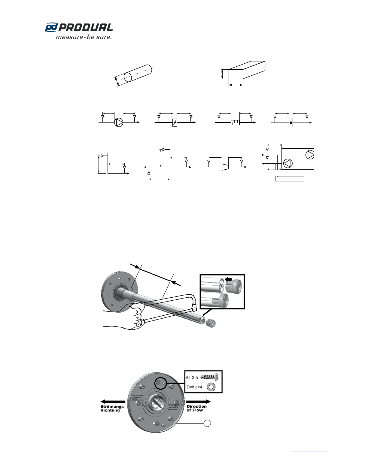
Hydraulic diameters, dh
dh=
2xHxW
H+W
H
W
dh=D
øD
Round duct Rectangular duct
Example of positioning (recommendations):
MIN 3xdhMIN 5xd
h
MIN 3xd
h
MIN 5xd
h
MIN 3xdhMIN 5xd
h
MIN 3xdhMIN 5xd
h
KR
M
KRMKRMKRMKRMKRMKRMKRM
Fan Damper Silencer Heater
KRM
KRM
KRM
KRM
KRM
KRM
KRM
KRM
MIN 5xd
h
MIN 3xd
h
MIN 5xd
h
MIN 5xd
h
MIN 3xd
h
MIN 3xd
h
MIN 5xd
h
MIN 5xd
h
MIN 3xd
h
Exhaust air
Supply air
Change in air duct
direction
Air duct forking Air duct narrowing / air
duct enlargement
Air duct device
Mounting procedure
1. Drill a hole Ø 43…44 mm in diameter at the intended mounting location.
NOTE: Installation of the measuring tube is possible either from the top, bottom or side of the channel for all duct
cross-sections (for round ducts as well).
2. Determine how long the measuring tube must be. If necessary, shorten the tube. Put the end plug back on up to
the stop collar.
min. 160 mm
IMPORTANT: Operation without end plug not permitted.
3. Determine the direction of flow and fit the adapter plate (A) so that the line on the adapter plate under the text
”Strömungsrichtung” is parallel to the flow direction. Four self-tapping screws serve for attaching it to the sheet
metal duct (not included in delivery).
A
USER GUIDE
KRM-1 & KRM-2
3 (8)
Produal Oy Keltakalliontie 18, 48770 Kotka FINLAND Tel: +358-10-219 9100 / Fax: +358-5-230 9210 info@produal.fi www.produal.com
Information is subject to change without prior notice.
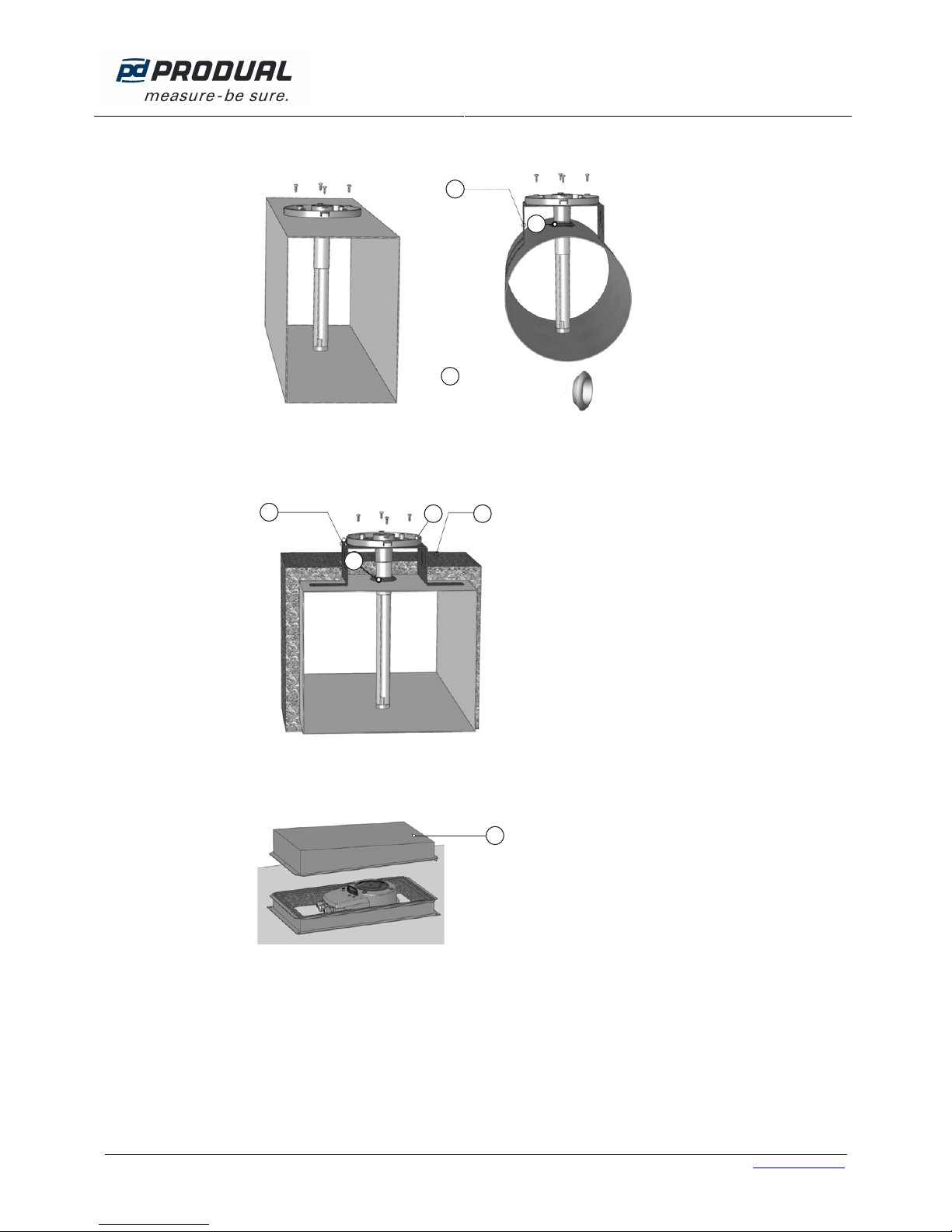
4. Installation on a rectangular air duct, see picture below. When installing on a circular air duct, use KS fitting plate
(B) and rubber bushing (C).
C
B
C
5. When installing on the air ducts with insulation, use the rubber bushing and insert it into opening in the air duct.
Install the fitting plate (B). Insert the assembled adapter plate (A) into the measuring tube by sliding the measuring tube through the grommet, and screw the adapter plate onto the fitting plate (B) using the 4 self-tapping
screws. Install the sensor with fitting plate into air duct. Then the insulation (D) can be installed.
B
D
C
A
6. When installing sensor outdoors or in cold environment, special WDG type housing (E) should be used. Housing
prevents the warm air in the smoke detector duct from condensing. The interior of the housing is insulated with
foam rubber.
E
Rubber
bushing, inner
oute
r
 Loading...