

Produal HLS 44 User Manual

USER GUIDE
HLS 44
V2.0 (08.03.2012)
1 (20)
Produal Oy Keltakalliontie 18, 48770 Kotka FINLAND Tel: +358-5-230 9200 / Fax: +358-5-230 9210 info@produal.fi www.produal.com
This user guide is for controllers with the software version 1.1.0, 1.1.1 or 1.1.2.
Room controller HLS 44
HLS 44 is a versatile room controller for individual room temperature
and VAV control applications. The controller can be connected to any
system that supports Modbus RTU protocol via the RS-485
connection. The bus is galvanically isolated from the controller's other
electronics. The controller has a display and touch buttons for
commissioning the controller and adjusting the user parameters,
temperature set point, for example.
The controller can control 0...10 V controlled actuators and thermal
actuators.
The output Y1 is reserved for variable air volume (VAV) control.
The Y2 output controls the fan speed:
1. EC motor: directly with the 0…10 V signal
2. 3-speed fan: using the FCRY 3 relay module
The controller has day and night operating modes. The modes can be
controlled by external card switch, PIR occupancy detector, over
Modbus and from menu. The day mode can be activated temporarily
for a specific time by touching the "man in house" button.
A demand based and energy saving ventilation can be implemented
with a separate carbon dioxide measurement connected to the U1
input.
TECHNICAL DATA
Supply 24 Vac/dc (20…28 V), < 1 VA
NOTE: Only the 0…10 V outputs work when using DC supply voltage.
Set point Day mode: 18…26 °C, ±3 °C, factory setting 21 °C
Night mode: Frost protection 8…50 °C, factory setting 17 °C
Accuracy (measuring
inaccuracy)
±0.5 °C
Dead zone (Dz) Day mode: 0.2...3 °C, factory setting 0.2 °C
Night mode: 0…10 °C, factory setting 6 °C
Proportional band (Xp) 1…32 °C, factory setting 1 °C
Integration time (Tn) 50…50000 s, factory setting 300 s
Inputs Internal temperature sensor
1 x ext. NTC10 or potential-free contact input (door or window contact or
condensation switch)
1 x DI, potential-free contact input (day/night mode control)
1 x 0...10 V (CO
2
measurement, external 0...10 V set point or 0...10 V temperature
transmitter)
Outputs
4 x 0...10 Vdc (Heating/cooling actuators, VAV or Fan speed control)
2 x 24 Vac Triac outputs, < 1 A/output (thermal actuators)
Communication RS-485 Modbus RTU, 9600/19200/38400/56000 bps, 8 data bits, parity
none/odd/even,1 stop bit (up to 247 devices per segment)
Display LCD
Buttons 4 touch buttons
Wiring terminals 1.5 mm
2
Operating conditions Humidity: 0…85 % rH non-condensing
Temperature: 0…50 ºC
Standards 2004/108/EY(EMC)
EN61000-6-3: 2001 (Emission)
EN61000-6-2: 2001 (Immunity)
Mounting Wall surface or on the standard flush mounting box
Housing IP20, ABS plastic
Dimensions (w x h x d) 87 x 86 x 32 mm
NOTE: The controller is available also with various button configurations.
USER GUIDE
HLS 44
2 (20)
Produal Oy Keltakalliontie 18, 48770 Kotka FINLAND Tel: +358-5-230 9200 / Fax: +358-5-230 9210 info@produal.fi www.produal.com
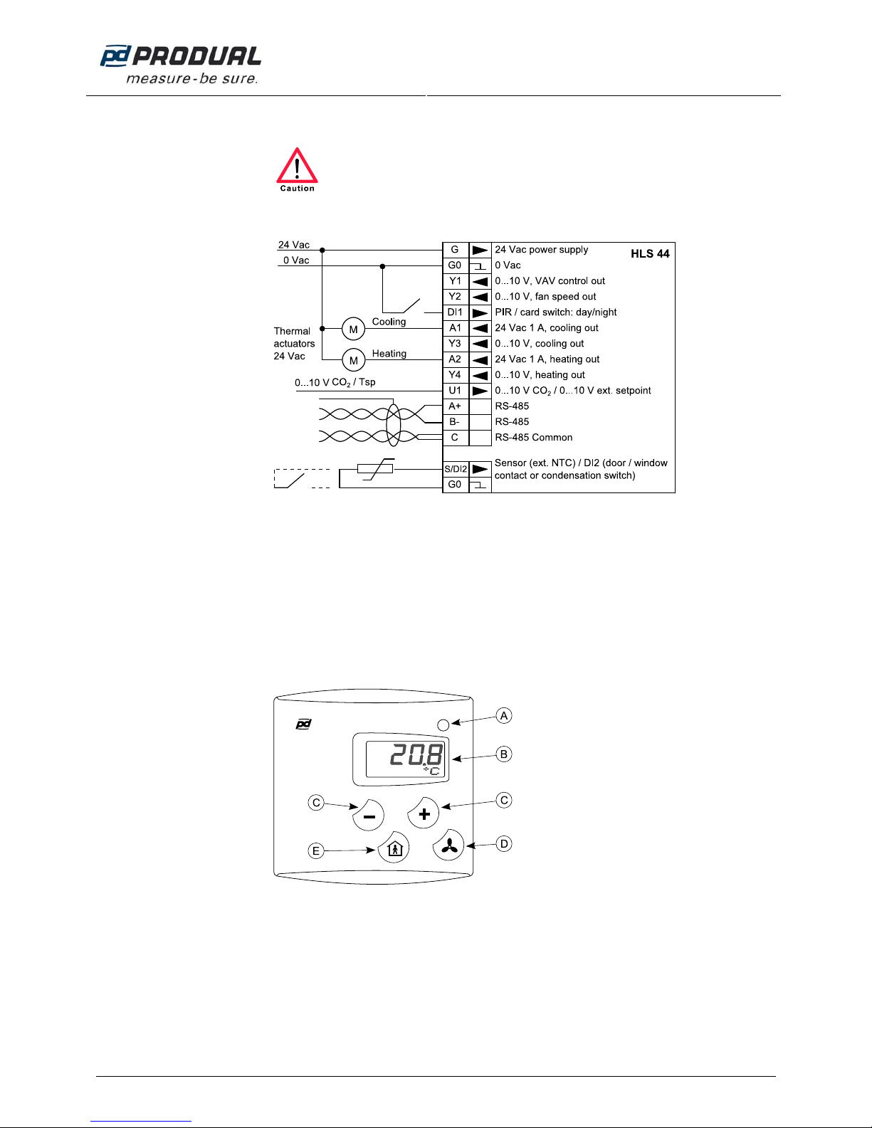
WIRING
Device connection and commissioning can only be carried out by qualified professionals.
Always make the connections while the power is switched off.
NOTE: The supply voltage potential must be the same in the controller and in the connected 24 Vac
actuators.
The maximum triac output current is 1 A. It is recommended to connect maximum of 4 thermal actuators
to the same controller output. The total current consumption must not exceed 1 A.
The triac outputs are protected with fuses that can only be changed by the manufacturer.
NOTE: Unused inputs and outputs can also be used for transferring other measuring and control
information over the Modbus.
OPERATING AFTER A POWER FAILURE
• The controller settings remain over the power failure.
• Overdrives made over the Modbus are cleared during the power failure.
USER MODE
A. Indicator light
o red = heating
o green = cooling
B. Display
o temperature or set point
o fan speed
C. Set point change buttons
The set point changes in larger steps
when the buttons are quickly pressed
several times in a row.
D. Fan speed control button
o 0 = STOP
o 1 = Speed 1
o 2 = Speed 2
o 3 = Speed 3
o A = AUTO
E. “Man in house” button
USER GUIDE
HLS 44
3 (20)
Produal Oy Keltakalliontie 18, 48770 Kotka FINLAND Tel: +358-5-230 9200 / Fax: +358-5-230 9210 info@produal.fi www.produal.com
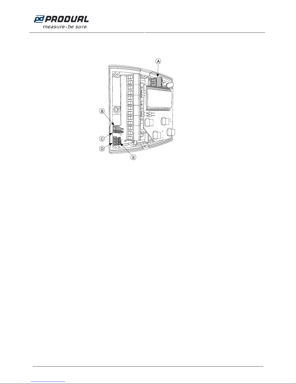
COMMISSIONING
NOTE: All the settings and parameters must be checked during the commissioning. This way you can
ensure the correct function in the selected application.
A. Terminals for external sensor or DI
contact
B. Bus termination (120 Ω)
o closed = terminated
o open = no termination
C. Configuration mode selector
o closed = configuration mode
o open = user mode (factory setting)
D. Terminal for HLS 44-SER commissioning
tool
E. Indicator lights
o green PWR = supply voltage OK
o yellow TX = transmission from
controller
o yellow RX = bus activity
Every controller must have an unique bus address (1...247). All controllers inside the same segment can
be controlled by sending a common command to address zero (broadcast). The function can be used for
testing during commissioning or common control of the day/night mode changes.
The controller settings can be supplied with controller buttons or by using the HLS 44-SER
commissioning tool. The commissioning tool settings can be loaded to the controller or the controller
settings can be loaded to the configuration tool and then to other controller.
Configuration through the menu:
1. Remove the cover.
2. Set configuration mode selector to closed position.
3. Make the settings required by the process.
4. Set the configuration mode selector to open position.
The controller returns to the user mode.
For configuration with the HLS 44-SER commissioning tool, see the commissioning tool instructions.
HLS 44-SER
There is four pre-programmed editable parameter profiles, one fixed configuration (=factory settings) and
five memory slots for user defined parameter profiles in the commissioning tool. The pre-programmed
profiles 1...3 work with both HLS 44 and HLS 44-V controllers and the profile 4 works only in the
HLS 44-V controller.
The pre-programmed parameter profiles are:
1. Heating with radiator and cooling with beam
2. Heating and cooling with fan coil unit
3. Heating with radiator, cooling with VAV and beam, demand based ventilation (CO
2
)
4. Heating by radiator, cooling with beam, on/off boosting damper control and light control

USER GUIDE
HLS 44
4 (20)
Produal Oy Keltakalliontie 18, 48770 Kotka FINLAND Tel: +358-5-230 9200 / Fax: +358-5-230 9210 info@produal.fi www.produal.com
MENU
Menu is activated by setting the configuration mode selector to the closed position. You can proceed in
the menu by touching the
and buttons. The values can be changed with the and buttons.
The value is accepted with the
button. The following menu structure contains the factory settings.
USER GUIDE
HLS 44
5 (20)
Produal Oy Keltakalliontie 18, 48770 Kotka FINLAND Tel: +358-5-230 9200 / Fax: +358-5-230 9210 info@produal.fi www.produal.com
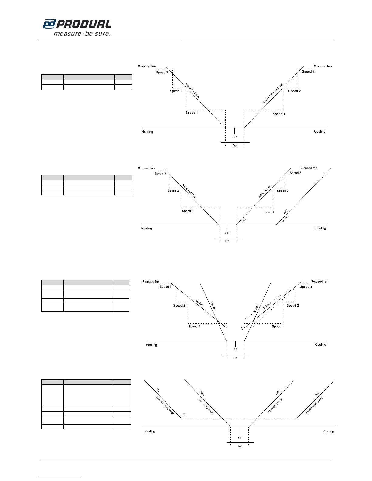
CONTROL METHODS
Heating and 1-stage cooling
Parameter Description choose
Cramp Cooling stages 1St
FAN Fan usage 3
Heating and 2-stage cooling
Parameter Description choose
Cramp
Cooling stages 2St
CSEq
Sequence of cooling stages Valve
FAN
Fan usage 3
Heating and 1-stage cooling, valve opens before the fan speed increases
Parameter Description choose
Cramp
Cooling stages 1St
Fan=
Fan stage simultaneously
with the valve stage OFF
FAN
Fan usage 3
FANLO
Fan output scaling, low end
*)
e.g.
20%
VAV heating and cooling
Parameter Description
choose
HVAV
VAV heating
NOTE: The heating stage
order is always the following:
1. Valve
2. VAV
On
Cramp
Cooling stages 2St
CSEq
Sequence of cooling stages Valve
Vmin% Minimum of VAV output *)
e.g.
20 %
FAN
Fan usage OFF
USER GUIDE
HLS 44
6 (20)
Produal Oy Keltakalliontie 18, 48770 Kotka FINLAND Tel: +358-5-230 9200 / Fax: +358-5-230 9210 info@produal.fi www.produal.com
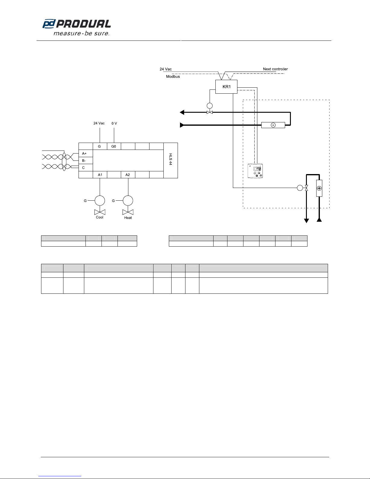
PROFILE 1: HEATING WITH RADIATOR AND COOLING WITH BEAM
Principle diagram:
Input DI1 U1 S/DI2
Output Y1 Y2 A1 A2 Y3 Y4
Thermal actuator x x
Note the following parameters:
Parameter
Modbus
register
Description
factory
setting
Min Max
Cramp 17 Cooling stages 1St 1St 2St 1St = 1 stage, 2St = 2 stages
MJAM 22 Valve jam prevention OFF ON OFF
Valves can jam when they are kept on the same position for a long time. The
valve jam prevention function can be activated in these kind of situations. When
the MJAM parameter is in “ON” position, valves are opened and closed for 5
minutes once a day.
 Loading...