

Page 1

3260A Series
High Power LOAD
Operation Manual
S/N: 9003260A02 REV: E
Page 2
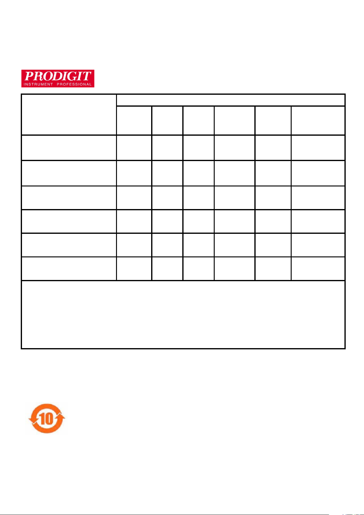
Material Contents Declaration
(材料含量宣称
材料含量宣称)
材料含量宣称材料含量宣称
(Part Name)
零件名称
铅(Pb) 汞(Hg)
Hazardous Substance (有毒有害物质或元素)
镉(Cd)
六价铬
(Cr6+)
多溴联苯
(PBB)
多溴二苯醚
(PBDE)
PCBA
(印刷电路装配件)
Electrical part not on
PCBA’s
未在PCBA上的电子零件
x
x
○
○
x
x
○ ○ ○
○ ○ ○
Metal parts
金属零件
○
○ ○
x
○ ○
Plastic parts
塑料零件
○
○ ○ ○
x
x
Wiring
电线
x
○ ○ ○ ○ ○
Package
封装
对销售之日的所售产品,本表显示, PRODIGIT 供应链的电子信息产品可能包含这些物质。注意:在所售产品中可能会也可
能不会含有所有所列的部件。This table shows where these substances may be found in the supply chain of Prodigit
electronic information products, as of the date of sale of the enclosed product. Note that some of the component types
listed above may or may not be a part of the enclosed product. ○:表示该有毒有害物质在该部件所有均质材料中的含量
均在SJ/T 11363-2006 标准规定的限量要求以下。○:Indicates that the concentration of the hazardous substance in all
homogeneous materials in the parts is below the relevant threshold of the SJ/T 113632006 standard. ×:表示该有毒有害
物质至少在该部件的某一均质材料中的含量超出SJ/T 11363-2006 标准规定的限量要求。×: Indicates that the
concentration of the hazardous substance of at least one of all homogeneous materials in the parts is above the relevant
threshold of the SJ/T 11363-2006 standard.
Note(注释):
1.Prodigit has not fully transitioned to lead-free solder assembly at this moment;However, most of the components
used are RoHS compliant.
(此刻,Prodigit 并非完全过渡到无铅焊料组装;但是大部份的元器件一至于RoHS的规定。)
2. The product is labeled with an environment-friendly usage period in years.
The marked period is assumed under the operating environment specified in the product specifications.
(产品标注了环境友好的使用期限制(年)。所标注的环境使用期限假定是在此产品定义的使用环境之下。)
Example of a marking for a 10 year period:
(
例如此标制环境使用期限为10年)
x
○ ○ ○ ○ ○
Page 3

SAFETY SUMMARY
The following general safety precautions must be observed during all phases of operation, service, and
repair of this instrument. Failure to comply with these precautions or with specific warnings elsewhere in this
manual violates safety standards of design, manufacture, and intended use of the instrument. PRODIGIT
assumes no liability for the customer's failure to comply with these requirements.
GENERAL
This product is a Safety Class 1 instrument (provided with a protective earth terminal). The protective
features of this product may be impaired if it is used in a manner not specified in the operation instructions.
ENVIRONMENTAL CONDITIONS
This instrument is intended for indoor use in an installation category I, pollution degree 2 environments. It is
designed to operate at a maximum relative humidity of 80% and at altitudes of up to 2000 meters. Refer to
the specifications tables for the ac mains voltage requirements and ambient operating temperature range.
BEFORE APPLYING POWER
Verify that the product is set to match the available line voltage and the correct fuse is installed.
GROUND THE INSTRUMENT
This product is a Safety Class 1 instrument (provided with a protective earth terminal). To minimize shock
hazard, the instrument chassis and cabinet must be connected to an electrical ground. The instrument must
be connected to the ac power supply mains through a three conductor
power cable, with the third wire firmly connected to an electrical ground (safety ground) at the power outlet.
Any interruption of the protective (grounding) conductor or disconnection of the protective earth terminal will
cause a potential shock hazard that could result in personal injury.
FUSES
Only fuses with the required rated current, voltage, and specified type (normal blow, time delay, etc.) should
be used. Do not use repaired
Fuses or short circuited fuse holder. To do so could cause a shock or fire hazard.
DO NOT OPERATE IN AN EXPLOSIVE ATMOSPHERE.
Do not operate the instrument in the presence of flammable gases or fumes.
KEEP AWAY FROM LIVE CIRCUITS.
Operating personnel must not remove instrument covers. Component replacement and internal adjustments
must be made by qualified service personnel. Do not replace components with power cable connected.
Under certain conditions, dangerous voltages may exist even with the power cable removed. To avoid
injuries, always disconnect power, discharge circuits and remove external voltage sources before touching
components.
DO NOT SERVICE OR ADJUST ALONE.
Do not attempt internal service or adjustment unless another person, capable of rendering first aid and
resuscitation, is present.
DO NOT EXCEED INPUT RATINGS.
This instrument may be equipped with a line filter to reduce electromagnetic interference and must be
connected to a properly grounded receptacle to minimize electric shock hazard. Operation at line voltages or
frequencies in excess of those stated on the data plate may cause leakage currents in excess of 5.0 mA
peak.
DO NOT SUBSTITUTE PARTS OR MODIFY INSTRUMENT.
Because of the danger of introducing additional hazards, do not install substitute parts or perform any
unauthorized modification to the instrument. Return the instrument to a PRODIGIT ELECTRONICS Sales
and Service Office for service and repair to ensure that safety features are maintained.
Instruments which appear damaged or defective should be made inoperative and secured against
unintended operation until they can be repaired by qualified service personnel.
Page 4
DECLARATION OF CONFORMITY
Company Name: PRODIGIT ELECTRONICS CO., LTD
Address: 8/F, No.88, Baojhong Rd., Sindian City, Taipei County,Taiwan, R.O.C.
Declares under sole responsibility that the product as originally delivered
Product Names: DC/AC Electronic Loads
Model Numbers: 326XA、3261XA、3302C、3305C、3300C
(And other customized products based upon the above)
Product Options:
This declaration covers all options and customized products based on the above products.
Complies with the essential requirements of the Low Voltage Directive 73/23/EEC and the EMC Directive
89/336/EEC (including 93/68/EEC) and carries the CE Marking accordingly.
EMC Information:
Class I a sample of the product has been assessed with respect to CE-marking according to the Low Voltage
Directive (73/23/EEC& 93/68/EEC) and EMC Directive (89/336/EEC,92/31/EEC, & 93/68/EEC) and Found
to comply with the essential requirements of the Directives.
The Standard(s) used for showing the compliance and the full details of the results are given in the Test
Reports as detailed below:
Safety Information:
Safety standards following:
IEC 61010-1:2010 / EN 61010-1:2010
Feb. 21, 2011
Date
The holder of the verification is authorized to use this verification in connection with the EC declaration Of
conformity according to the Directives. The CE marking may only be used if all releveant and effective EC
Directives are complied with. Together with the manufacturer’s own documented production control, The
manufacturer (or his European authorized representative) can in his EC Declaration of Conformity Verify
compliance with the directives.
Page 5

3260A Series High Power Load Operation Manual
Table & Contents
CHAPTER 1 INTRODUCTION................................................................................... 1
1-1 General Description ...................................................................................... 1
1-2 Characteristics of 3260A Series High Power Electronic Load ...................... 4
1-3 Accessories .................................................................................................. 4
1-4 Option ........................................................................................................... 4
1-5 Specification ................................................................................................. 5
1-6 System Block Diagram ................................................................................. 8
CHAPTER 2 INSTALLATION .................................................................................... 9
2-1 Inspection ..................................................................................................... 9
2-2 Check line voltage ........................................................................................ 9
2-3 Grounding requirements ............................................................................. 10
2-4 Adjust the feet............................................................................................. 10
2-5 Rack mount ................................................................................................ 10
2-6 Environmental requirements ....................................................................... 10
2-7 Repairing .................................................................................................... 10
2-8 GPIB connection......................................................................................... 11
2.9 RS-232C Connection.................................................................................. 11
2-10 Remote control Port................................................................................... 12
CHAPTER 3 MANUAL OPERATION ...................................................................... 13
3-1 Description of Front Panel ........................................................................ 13
3-2 STORE / RECALL operation ...................................................................... 20
3-3 AUTO SEQUENCE testing function description ......................................... 21
3-4 Setting of Freq. & Selection of Bank & Sync............................................... 24
3-5 Initial setting parameter of 3260A Series High Power Electronic Load ....... 25
3-6 Consideration of Load Input Connector and Connecting Lead Wire........... 29
3.7 Rough Tuning, Fine Tuning & Increment & Decrement Adjustment of Load
Current........................................................................................................ 30
3-8 Imonitor (Output)......................................................................................... 32
3-9 Operation Flow Chart of 3260A Series Electronic Load.............................. 33
3-10 Protection Features ................................................................................... 34
3-11 Load ON voltage adjustment ..................................................................... 36
CHAPTER 4 GPIB/RS-232C OPERATION ............................................................. 37
4-1 Introduction................................................................................................. 37
4-2 The summary of RS-232 interface and command ...................................... 37
4-3 3260A Series GPIB/RS-232C COMMAND LIST ........................................ 38
4-4 The description of abbreviation................................................................... 40
4-5 GPIB/RS-232C command description ........................................................ 41
CHAPTER 5 APPLICATION .................................................................................... 56
5-1 CC Operation Mode Application ................................................................. 56
5-2 CR Operation Mode Application ................................................................. 57
5-3 LIN Operation Mode Application ................................................................. 58
APPENDIX I 3260A R1.00 EDITION WAVE FORM DATA BANK ............................ 1
APPENDIX II SETTING OF AC OR DC ELECTRONIC LOAD.................................. 1
Page 6

Figures
FIG.1-1 ELECTRONIC LOAD POWER CURVE ......................................................................................................1
FIG.1-2 CHARACTERISTICS OF C.C. MODE .........................................................................................................2
FIG.1-3 CHARACTERISTICS OF C.R. MODE .........................................................................................................2
FIG.2-1 SET OF SWITCH .............................................................................................................................................9
FIG.2-2 AC LINE RECEPTACLE..............................................................................................................................10
FIG.2-3 3260A SERIES HIGH POWER ELECTRONIC LOAD FRONT PANEL KEY SWITCH ....................11
FIG.2-4 DIAGRAM OF REMOTE CONTROL PORT ............................................................................................12
FIG.3-1 FRONT PANEL OF 3260A SERIES HIGH POWER ELECTRONIC LOAD ........................................13
FIG.3-2 TYPICAL WAY FOR CONNECTING 3260A SERIES HIGH POWER ELECTRONIC LOAD .........18
FIG.3-3 AUTO SEQ FUNCTION OPERATION FLOW CHART ..........................................................................21
FIG.3-5 TEST MODE OPERATION FLOW-CHART.............................................................................................23
FIG.3-6 DESCRIPTION OF SYNC. ...........................................................................................................................25
FIG 4-1 RS-232 INTERFACE DIAGRAM.................................................................................................................37
Tables
TABLE 1-1 3260A SERIES SPECIFICATION................................................................................7
TABLE 3-1 3260A SERIES HIGH POWER ELECTRONIC LOAD IMONITOR SPECIFICATION.19
TABLE 3-2 3260A BUILT-IN WAVE FORM DATA BANK ............................................................24
TABLE 3-3 3260A INITIAL CONDITION SETTING......................................................................26
TABLE 3-4 3261A INITIAL CONDITION SETTING......................................................................26
TABLE 3-5 32611A INITIAL CONDITION SETTING....................................................................26
TABLE 3-6 32612A INITIAL CONDITION SETTING....................................................................27
TABLE 3-7 32613A INITIAL CONDITION SETTING....................................................................27
TABLE 3-8 32614A INITIAL CONDITION SETTING....................................................................27
TABLE 3-9 32615A INITIAL CONDITION SETTING....................................................................28
TABLE 3-10 32616A INITIAL CONDITION SETTING..................................................................28
TABLE 3-11 3260A SERIES ROUGH TUNING, FINE TUNING & INCREMENT & DECREMENT
ADJUSTMENT OF LOAD CURRENT..........................................................................................31
TABLE 3-12 3260A SERIES OVER VOLTAGE PROTECTION SETTING VALUE ......................34
TABLE 3-13 3260A SERIES OVER CURRENT PROTECTION SETTING VALUE......................35
TABLE 3-14 3260A SERIES OVER POWER PROTECTION SETTING VALUE..........................35
TABLE 4-1 GPIB/RS-232C SETTING COMMAND SUMMARY ...................................................38
TABLE 4-2 GPIB/RS-232C QUERY COMMAND SUMMARY......................................................39
TABLE 4-3 GPIB/RS-232C COMMAND TERMINATOR ..............................................................40
TABLE 4-4 WAVEFORM INFORMATION ...................................................................................45
Page 7
PRODIGIT 3260A Series Operation Manual 1
V
Chapter 1 Introduction
1-1 General Description
3260A Series High Power Electronic Load is used for evaluation of the specification
characteristics of AC/DC high power suppliers and the service life characteristics of batteries.
Especially for step wave-form, square wave-form UPS, inverter device.
3260A Series High Power Electronic Load can be used to work with GPIB/RS-232C interface
and panel manual operation can be made available.
50 V
50 V
50 V
50 V
50 V
50 V
60 V
50 V
60 V
50 V
70 V
60 V
75 V
(F) W CONTOUR
(E)
4 A 12 A 1200 W
8 A 24 A 2400 W
6 A 18 A 1800 W
12 A 36 A 3600 W
18 A 54 A 5400 W
24 A 72 A 7200 W
24 A 72 A 7200 W
30 A 90 A 9000 W
30 A 90 A 9000 W
36 A 108 A 10800 W
36 A 108 A 10800 W
42 A 126 A 12600 W
42 A 126 A 12600 W
I
(A)
(B)
(C)
(D)
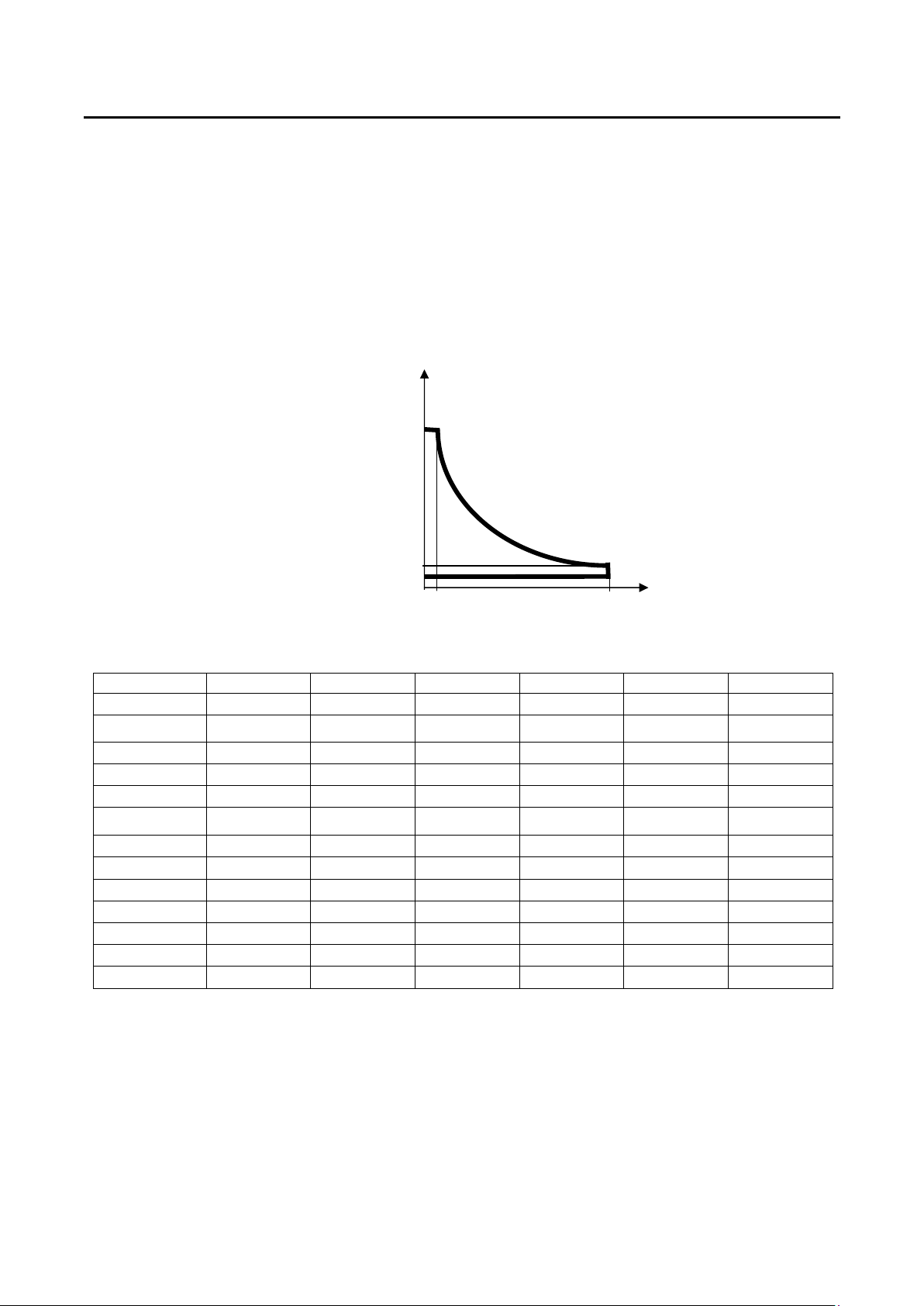
Fig.1-1 Electronic Load Power Curve
Model (A) V (B) V (C) V (D) A (E) A (F) W
3260A
32601A
3261A
32611A
32612A
32613A(CC)
32613A(LIN)
32614A(CC)
32614A(LIN)
32615A(CC)
32615A(LIN)
32616A(CC)
32616A(LIN)
The work mode of 3260A Series High Power Electronic Load includes C.C, Linear C.C., C.R.
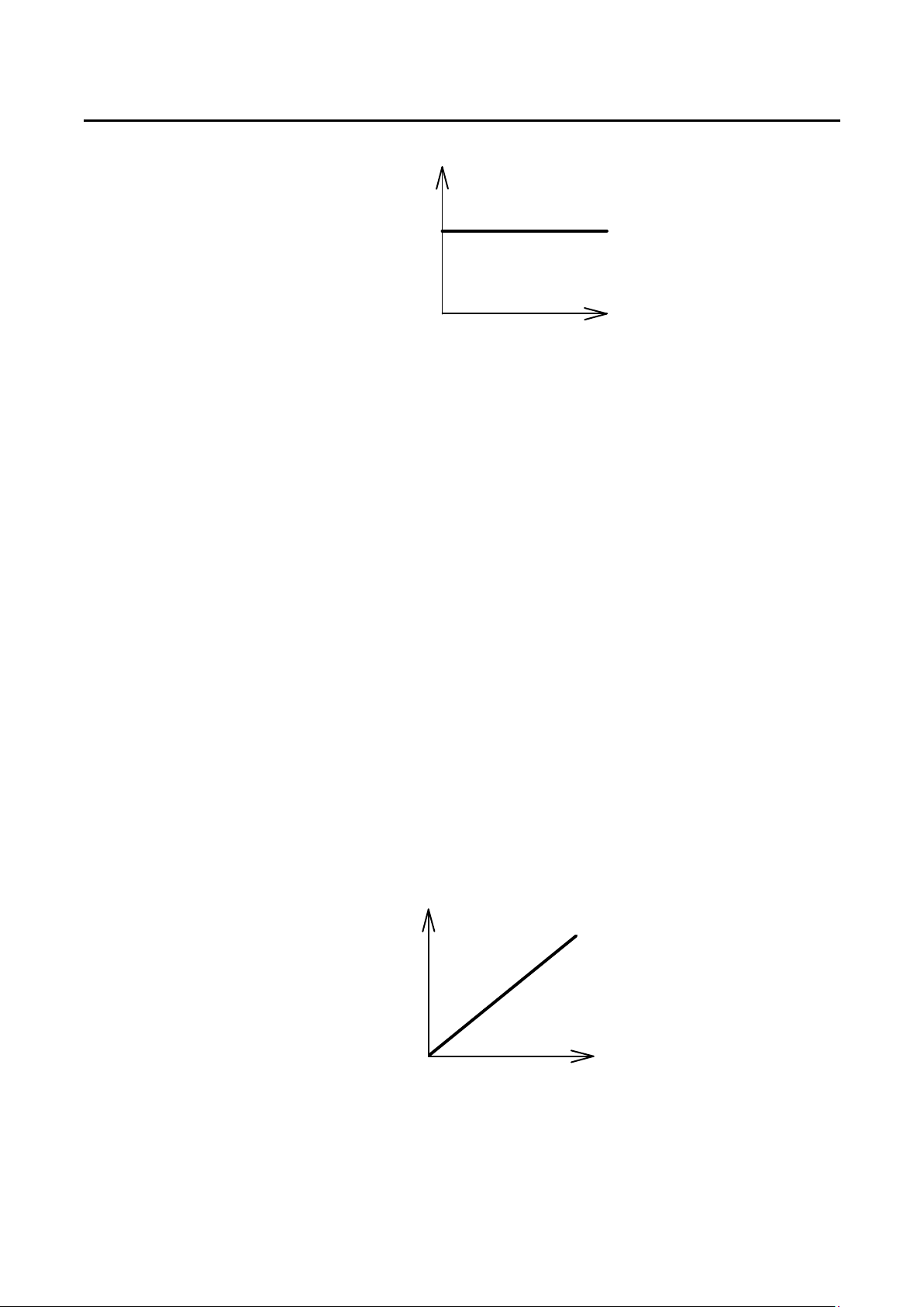
C.C. Mode
During C.C. mode, the load current input into 3260A Series High Power Electronic Load
depends on the current setting regardless of the input voltage, e.g., the current setting
remains unchanged. Please refer to Fig.1-9 below:
300 V
300 V
300 V
300 V
300 V
300 V
300 V
300 V
300 V
300 V
300 V
300 V
300 V
100 V
100 V
100 V
100 V
100 V
100 V
100 V
100 V
100 V
100 V
100 V
100 V
100 V
Page 8
2 PRODIGIT
Linear C.C. Mode
During Linear C.C. mode, the load current input into 3260A Series High Power Electronic
Load depends on the current setting regardless of the input voltage, e.g., the current setting
remains unchanged. Please refer to Fig.1-9. The load input current signal will follow input
voltage signal, That is useful for step wave-form and square wave-form device.
The LIN mode is within a AGC circuit and the control signal will response with input voltage.
We call it LIN mode.
The AGC circuit produces a constant amplitude output signal so long as the amplitude of the
input signal exceeds an adjustable reference voltage applied to the peak detector. The
reference voltage may be changed to change the range of input voltage resulting in a
constant-amplitude output.
The AGC circuit responds almost instantly to control a sudden increase in input voltage.
The AGC circuit is especially suitable for Step waveform, Square waveform and the input
voltage with distortion waveform.
C.R. Mode
During C.R. mode, the load current input into 3260A Series High Power Electronic Load
depends on the resistance setting. At this time, the load current is in direct proportion to input
voltage, e.g. the resistance setting remains unchanged. Please refer to Fig. 1.10 below
I
CC
CURRENT SETTING
LOAD
CURRENT
INPUT VOLTAGE
Fig.1-2 Characteristics of C.C. Mode
I
V
LOAD
CURRENT
INPUT VOLTAGE
Fig.1-3 Characteristics of C.R. Mode
RESISTANCE
SETTING
V
Page 9

PRODIGIT 3260A Series Operation Manual 3
The load setting of 3260A Series High Power Electronic Load and the load condition setting
of the front panel can be made through the front panel manual operation, GPIB command.
The load voltage and current can be transmitted to the computer through GPIB bus. For
operation of GPIB, please refer to chapter 4 GPIB Operation.
Page 10

4 PRODIGIT
1-2 Characteristics of 3260A Series High Power Electronic Load
1.2.1 Interface function of full GPIB control, including setting of load condition and readback of Vmeter and Ameter.
1.2.2 Dual High Accuracy/High Resolution 4 1/2 digit Vmeter and Ameter.
1.2.3 In CC mode, frequency range for DC , 0.1~400 Hz.
1.2.4 In CC mode, the settable Crest Factor can be set to Maximum 3.5.
1.2.5 Automatic judging ability for GO/NG.
1.2.6 Switch-able automatic voltage sensing ability.
1.2.7 Protection functions include Over - Voltage, Over - Current, Over - Power and Over Temperature.
1.2.8 Software calibration ability.
1.2.9 Cooling fan control device with revolution change function.
1.2.10 Isolated Current Monitor BNC output with full scale of 10V.
1-3 Accessories
1.3.1 Vsense Input BNC Connector 1 PC
1.3.2 Banana Terminal (Black) 1 PC
1.3.3 Banana Terminal (Red) 1 PC
1.3.4 King-Size Hook-Type Terminal 2 PC
1.3.5 3260A Series High Power AC/DC Electronic Load Operation Manual 1 PC
1-4 Option
1.4.1 GPIB cable 1 M
1.4.2 GPIB cable 2 M
1.4.3 9931 Remote Controller 1 Set
1.4.4 D-SUB 9 Pin to D-SUB 9 Pin cable 1 M
Page 11
PRODIGIT 3260A Series Operation Manual 5
0~54/54~108
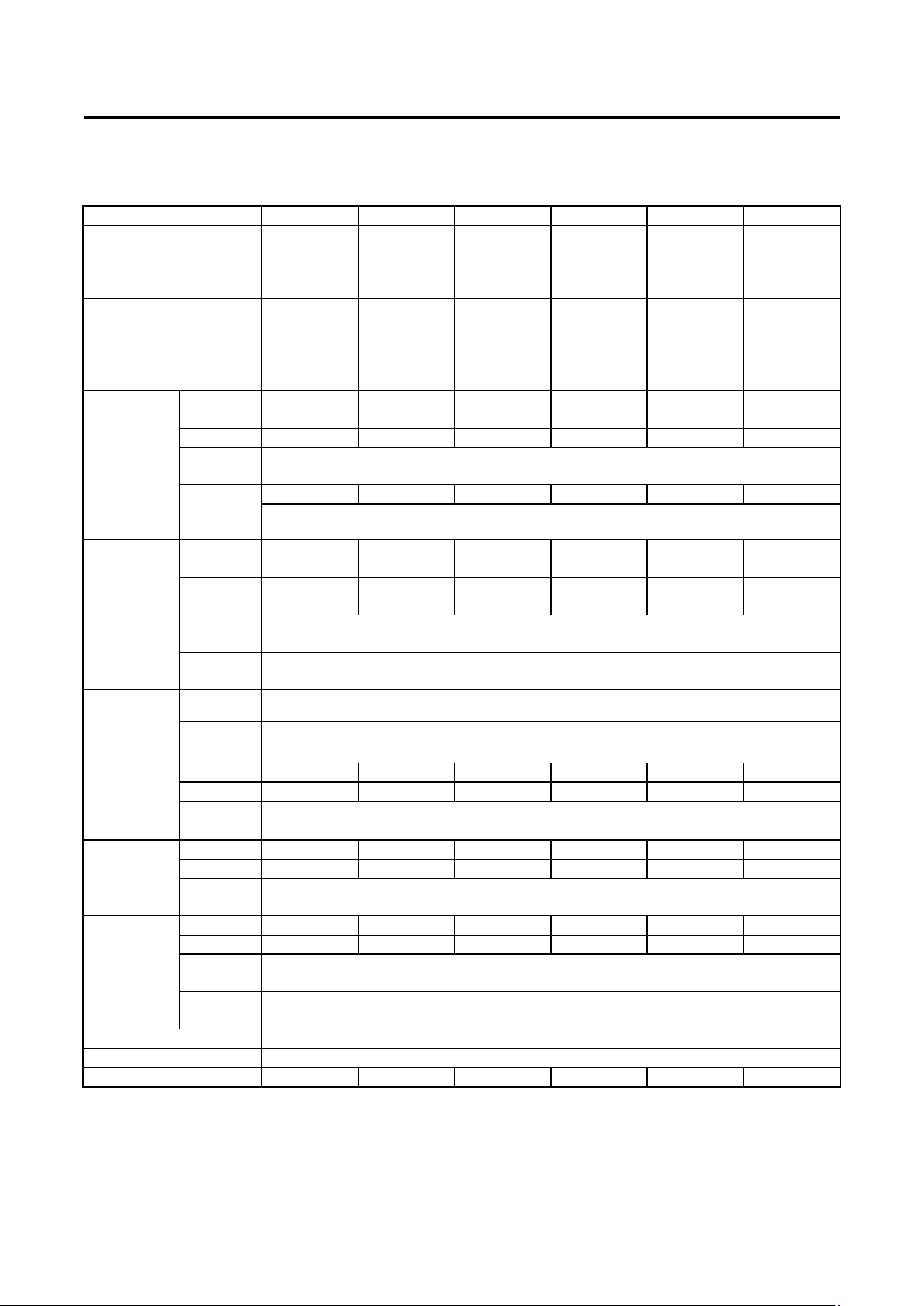
1-5 Specification
MODEL 3261A 32611A 32612A 32613A 32614A 32615A
LOAD INPUT RATINGS
Power (VA)
Current(Ampere)
Voltage(Volt)
PROTECTION:
Over Power Protection
Over Current Protection
Over Voltage Protection
Over Temp. Protection
Range
CC MODE
&
Linear CC
MODE
CR MODE
CREST
FACTOR
(CCMODE
ONLY)
VOLTAGE Range 300 V 300 V 300 V 300 V 300 V 300 V
READBACK Resolution
V METER Accuracy
CURRENT Range 18 A 36 A 54 A 72 A 90 A 108 A
READBACK Resolution 0.001 A 0.01 A 0.012 A 0.012 A 0.01 A 0.012 A
A METER Accuracy
WATT Range 1800 W 3600 W 5400 W 7200 W 9000W 10800 W
READBACK Resolution
W METER
VA METER Vrms×Arms Correspond To Vrms and Arms
FREQUENCY Range DC , 40~400 Hz(CC Mode) ; DC , 0.1~400 Hz(LIN,CR Mode)
Imonitor (Isolated) 4.5 A/V 9 A/V 13.5 A/V 18 A/V 22.5A/V 27 A/V
Resolution 2.25/4.5 mA 4.5/9 mA 6.75/13.5 mA 9/18 mA
Accuracy ±( 0.5﹪ of setting + 1﹪ of range );
Low
Current
Accuracy
Range II/I
Resolution
Accuracy ( 0.5﹪ of setting + 2﹪ of range );
Under 5 ﹪
F.S.Current
Range
Resolution
Accuracy ±( 0.5﹪ of reading + 2﹪ of range );
Under 5 ﹪
F.S.Current
1800 VA
18 Arms
50~300 Vrms
≒ 1890 VA
≒ 18.9 A
≒ 315 V
85℃
0~9/9~18
A
0~0.9 A 0~1.8 A 0~2.7 A 0~3.6 A 0~4.5 A 0~5.4 A
3.333~13.33
2~53.332K
0.019/0.076
mS
0.1 V 0.1 V 0.1 V 0.1 V 0.1 V 0.1 V
0.1 W 1 W 1.2 W 1.2 W 1W 1.2 W
3600 VA
36 Arms
50~300 Vrms
≒ 3780 VA
≒ 37.8 A
≒ 315 V
85℃
0~18/18~36 A 0~27/27~54 A 0~36/36~72 A 0~45/45~90
±0.5﹪ of (setting + range)@ 50/60Hz
± 2 % of (setting + range)
1.667~6.668
~26.668K
0.037/0.148
mS
±0.5﹪ of (setting + range)@ 50/60Hz
±2﹪ of (setting + range)
√2 ~ 3.5 / 1.5 ~ 1.9 / 3.0 ~ 3.4
±( 0.5﹪ of reading + 0.2﹪of range )
DVM under 1% don’t display.
±( 0.5﹪ of reading + 2﹪ of range );
±0.5﹪ of (reading + range)@ 50/60Hz
±0.5﹪ of (reading + range)@ 50/60Hz
±3﹪ of (setting + range)
5400 VA
54 Arms
50~300 Vrms
≒ 5670 VA
≒ 56.7 A
≒ 315 V
85℃
1.111~4.444
~17.776K
0.056/0.224
mS
0.5 / 0.1 / 0.1
7200 VA
72 Arms
50~300 Vrms
≒ 7560 VA
≒ 75.6 A
≒ 315 V
85℃
0.833~3.333
~13.33K
0.075/0.300
mS
9000 VA
90 Arms
50~300 Vrms
≒ 9450 VA
≒ 94.5 A
≒ 315 V
85℃
A
11.25/21.5 mA
0.666~2.666
~10.666K
0.0937/0.375
mS
10800 VA
108 Arms
50~300 Vrms
≒ 11340 VA
≒ 113.4 A
≒ 315 V
85℃
A
13.5/27 mA
0.556~2.224
~8.888K
0.113/0.452
mS
Page 12
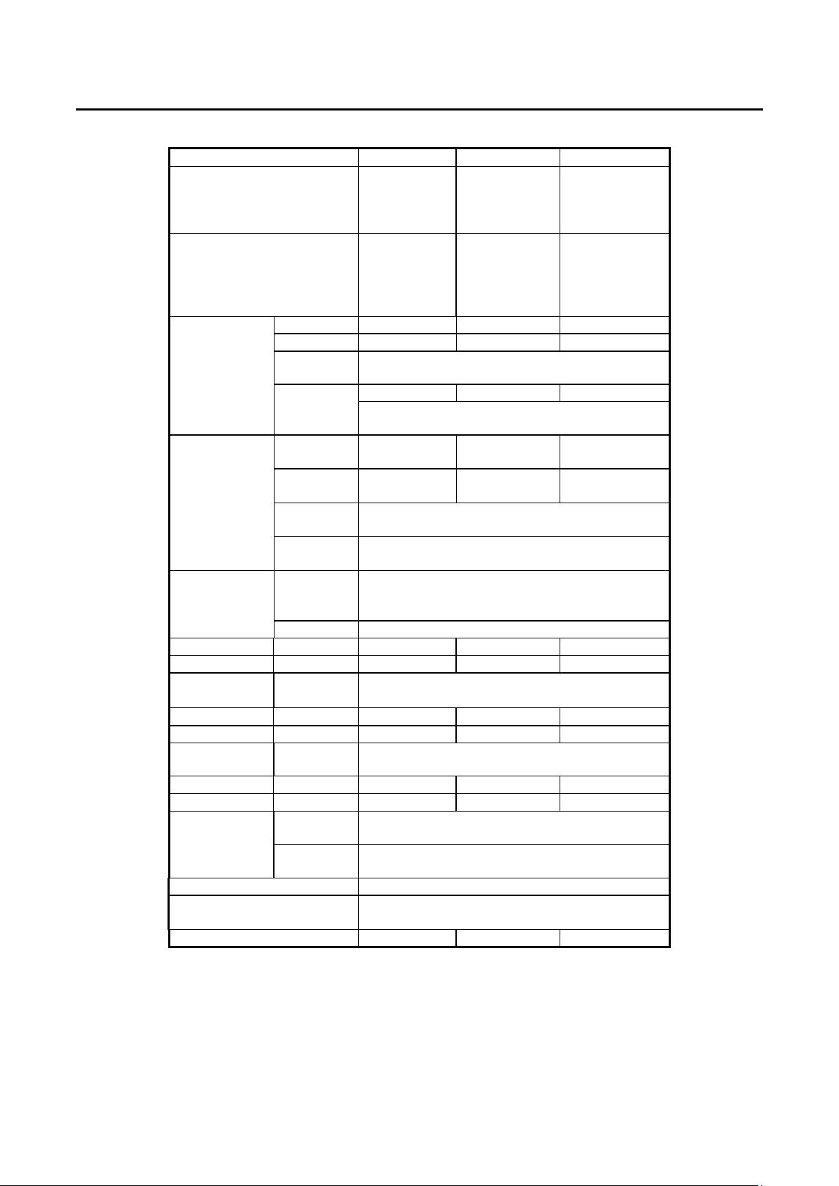
6 PRODIGIT
MODEL 3260A 32601A 32616A
LOAD INPUT RATINGS
Power (VA)
Current(Ampere)
Voltage(Volt)
PROTECTION:
Over Power Protection
Over Current Protection
Over Voltage Protection
Over Temp. Protection
Range 0~6/6~12 A 0~12/12~24 A 0 ~ 63/126 A
CC MODE
&
Linear CC
MODE
CR MODE
CREST
FACTOR
(CCMODE
ONLY)
VOLTAGE Range 300 V 300 V 300 V
READBACK Resolution 0.1 V 0.1 V 0.1 V
V METER Accuracy
CURRENT Range 12 A 24 A 126 A
READBACK Resolution 0.001 A 0.01 A 0.014 A
A METER Accuracy
WATT Range 1200 W 2400 W 12600 W
READBACK Resolution 0.1 W 0.1 W 1 W
W METER
VA METER Vrms×Arms Correspond To Vrms and Arms
FREQUENCY Range DC , 40~400 Hz(CC Mode) ;
Imonitor (Isolated) 3 A/V 6 A/V 31.5A/V
Resolution 1.5/3 mA 3/6 mA 15.75/31.5mA
Accuracy
Low
Current
Accuracy
Range II/I
Resolution
Accuracy
Under 5 ﹪
F.S.Current
Range
Resolution 0.5 / 0.1 / 0.1
Accuracy
Under 5 ﹪
F.S.Current
1200 VA
12 Arms
50~300 Vrms
≒ 1260 VA
≒ 12.6 A
≒ 315 V
85℃
±( 0.5﹪ of setting + 1﹪ of range );
±0.5﹪ of (setting + range)@ 50/60Hz
0~0.6 A 0~1.2 A 0 ~ 6.3 A
± 2 % of (setting + range)
5~20~
80K
0.013 /
0.052 mS
±( 0.5﹪ of setting + 2﹪ of range );
±0.5﹪ of (setting + range)@ 50/60Hz
±2﹪ of (setting + range)
√2 ~ 3.5 / 1.5 ~ 1.9 / 3.0 ~ 3.4
±( 0.5﹪ of reading + 0.2﹪of range )
DVM under 1% don’t display.
±( 0.5﹪ of reading + 2﹪ of range );
±0.5﹪ of (reading + range)@ 50/60Hz
±( 0.5﹪ of reading + 2﹪ of range );
±0.5﹪ of (reading + range)@ 50/60Hz
±3﹪ of (setting + range)
DC , 0.1~400 Hz(LIN,CR Mode)
2400 VA
24 Arms
50~300 Vrms
≒ 2520 VA
≒ 25.2 A
≒ 315 V
85℃
2.5~10~
40K
0.025 /
0.1 mS
12600VA
126Arms
60~300Vrms
≒ 13230 VA
≒ 132.3 A
≒ 315 V
85℃
0.476~1.904~
7.616K
0.5252S /
0.1313mS
Page 13
PRODIGIT 3260A Series Operation Manual 7
200V/230V±10﹪
1A/250V (5*20mm)
100 W
EACH UNIT
LINE 100V/115V±10﹪
AC INPUT
FREQUENCY 50/60 HZ
FUSE 2A/250V (5*20mm)
MAX. POWER CONSUMPTION
DIMENSIONS (W*H*D) 440 mm*177 mm*445 mm / EA
WEIGHT NET : 23.6 Kg / EA
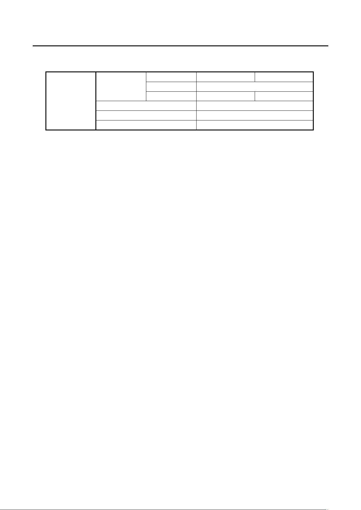
Table 1-1 3260A Series Specification
Page 14
8 PRODIGIT
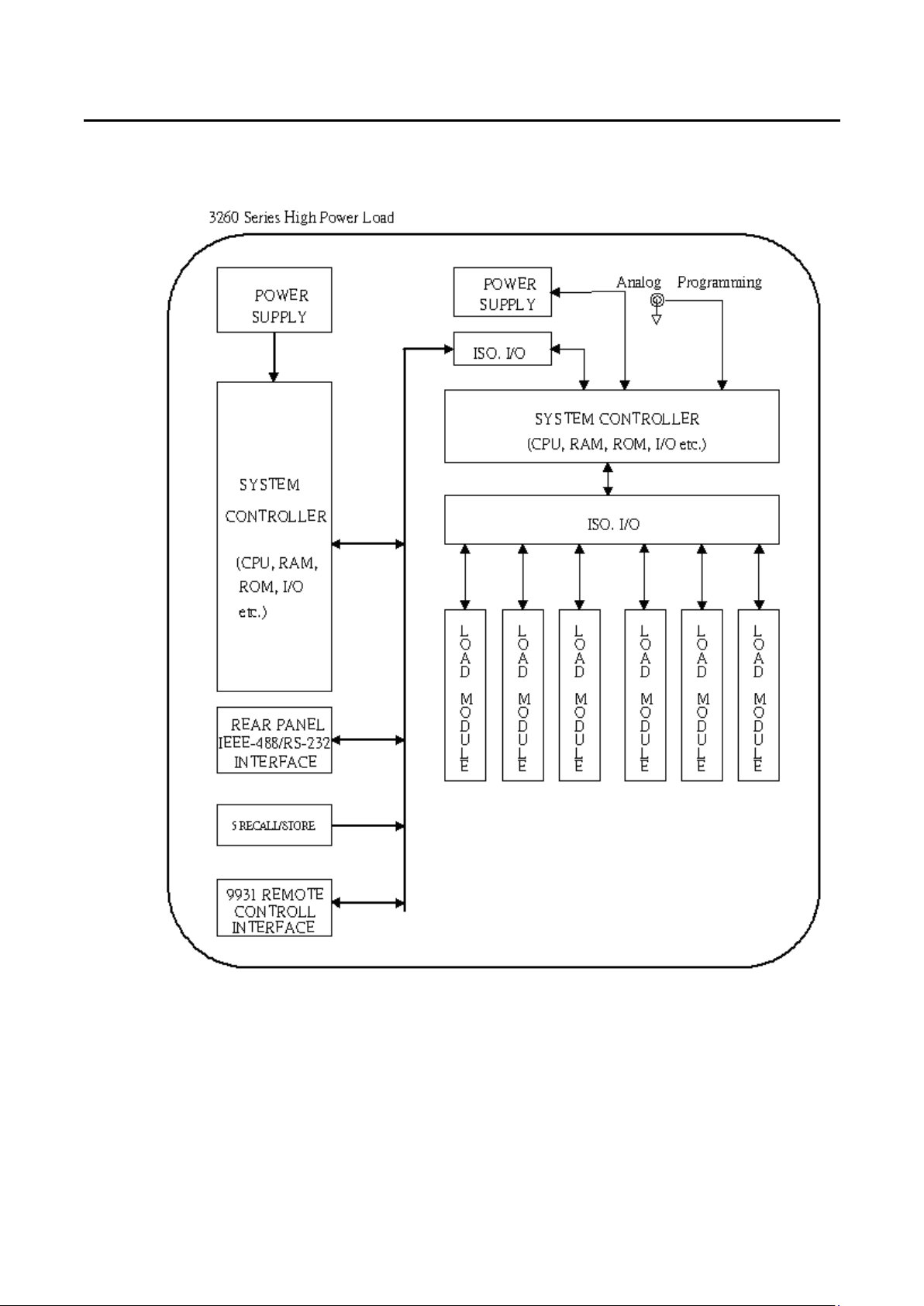
1-6 System Block Diagram
Page 15

PRODIGIT 3260A Series Operation Manual 9
Chapter 2 Installation
2-1 Inspection
The 3260A Series High Power Electronic Load was carefully inspected before shipment. If
instrument damage has occurred during transport, please inform Prodigit's sales and service
office or representative.
Your 3260A Series High Power Electronic Load was shipped with a power cord for the type
of outlet used at your location. If the appropriated cord was not included, please contact your
nearest Prodigit sales office to obtain the correct cord. Refer to " check line voltage " to check
the line voltage selection and fuse type.
2-2 Check line voltage
The 3260A Series High Power Electronic Load can operation with 115, 230Vac input as
indicated on the label on the rear panel.
Make sure that the factory check mark correspond to your nominal line voltage. Skip this
procedure if the label is corrected marked.
2.2.1 With the 3260A Series High Power Electronic Load power OFF, disconnect the
power cord.
2.2.2 Refer the drawing on the rear panel in Fig 2-1, set the switches to the proper voltage
as describe in the following:
SYNC INPUT
RANGE
1
1
5
Fig.2-1 SET OF SWITCH
2.2.3 Mark the correct voltage on the rear panel of 3260A Series High Power Electronic
Load.
2.2.4 Check the rating of the line fuse and replace it with the correct fuse if necessary.
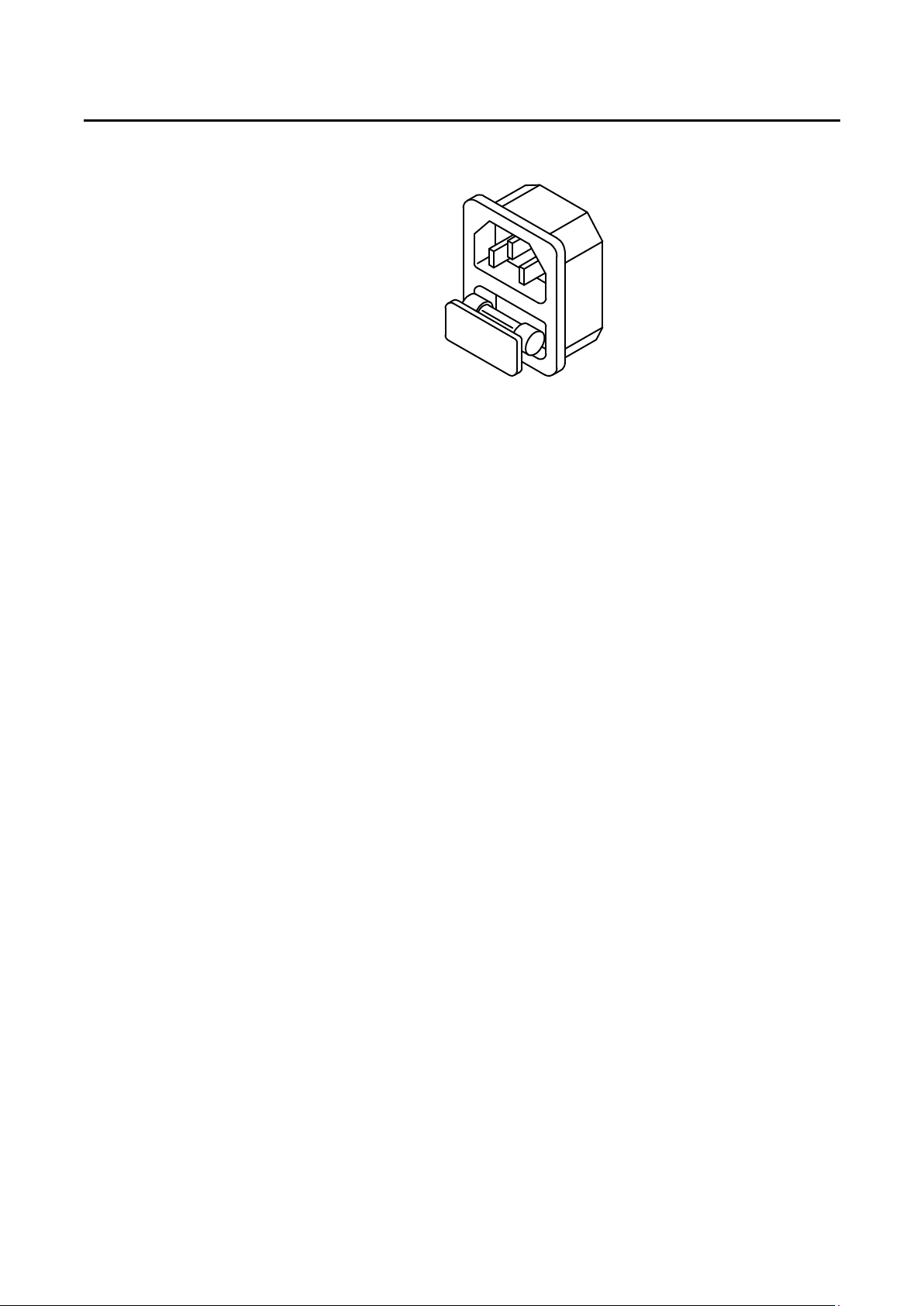
2.2.5 The line fuse is located below the AC line receptacle see Fig 2-2. With the power
cord removed, use a small screwdriver to extract the fuse holder from under the AC
socket. Replace the fuse with the appropriate type as indicated in Table 1-1. These
fuses are normal-blow fuses.
Page 16
10 PRODIGIT
2.2.6 Reinstall fuse holder and connect the power cord.
2-3 Grounding requirements
The 3260A Series High Power Electronic Load is equipped with three conductor cable which
plugs in an appropriate receptacle to ground the instrument's cover.
Fig.2-2 AC LINE RECEPTACLE
2-4 Adjust the feet
The 3260A Series High Power Electronic Load is equipped with feet and tilt stands installed
and is ready for used as a bench instrument.
The feet provide a good viewing angle for bench-top use.
2-5 Rack mount
The 3260A Series High Power Electronic Load is designed to permit mounted in a standard
19 inches rack for system application.
2-6 Environmental requirements
The operating temperature should keep between 0 degree and 40 degree, while the ideal
operating temperature is 25 ± 5 degree.
2-7 Repairing
If the instrument is damaged, please attach a tag to the instrument to identify the owner and
indicated the require service or repairing. And inform the Prodigit sales and service office or
representative.
Page 17
PRODIGIT 3260A Series Operation Manual 11
2-8 GPIB connection
The GPIB connector on the rear panel connects the 3260A Series High Power Electronic
Load mainframe to the controller and to other GPIB devices. An GPIB system can be
connected in any configuration (star, linear, or both) as long as
2.8.1 The maximum number of devices including the controller is no more than 15.
2.8.2 The maximum length of all cable in no more than 2 meters times the number of
devices connected together, up to 20 meters maximum.
Please make sure the lock screws are firmly hand - tightened, use a screw-driver
only for the removal of screws. Fig 2-3 shows the rear panel of 3260A Series High
Power Electronic Load mainframe, the GPIB connector is located on the rear panel of
3260A Series High Power Electronic Load mainframe. The GPIB address of the
3260A Series High Power Electronic Load mainframe is set on front panel.
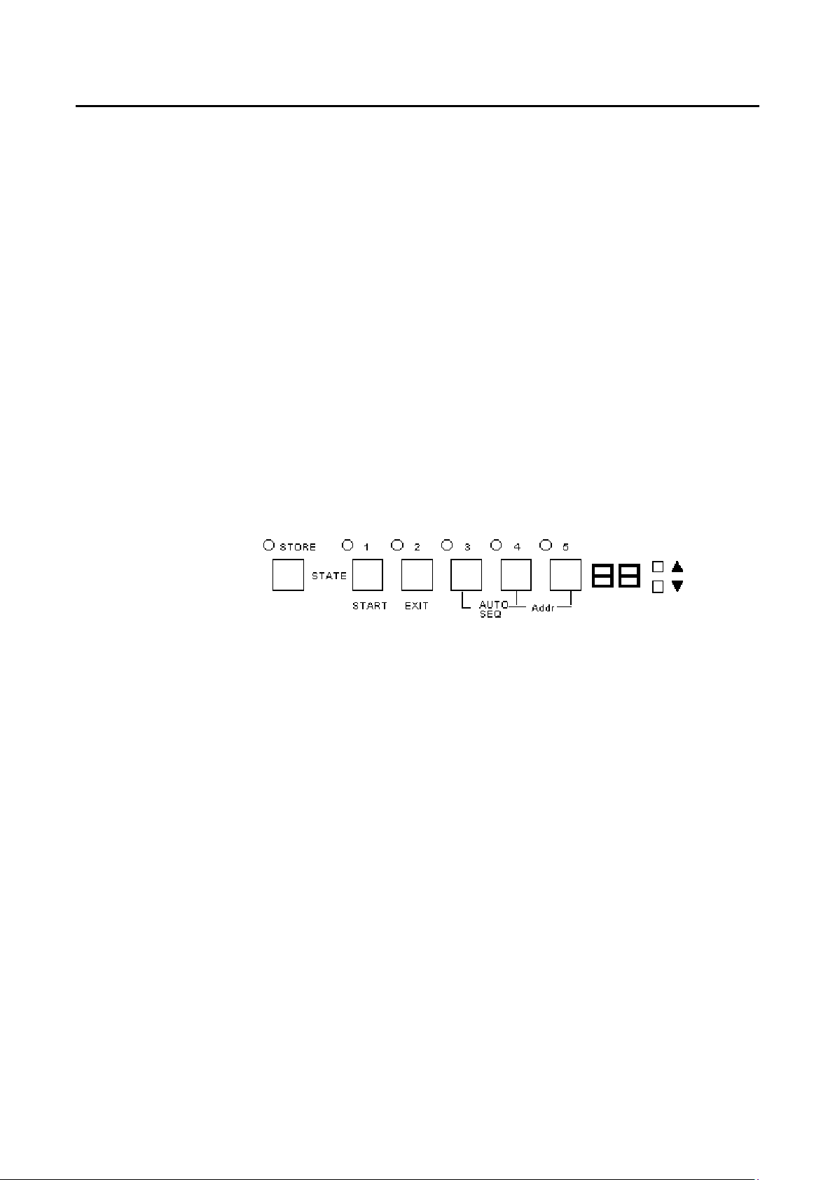
2.8.3 GPIB address setting:
GPIB address is set by press STATE 4 + STATE 5 simultaneously, press UP or
DOWN key to select 0-31 address number, press STATE 2 to exit GPIB address
setting mode.
Fig.2-3 3260A Series High Power Electronic Load front panel key switch
2.9 RS-232C Connection
The RS-232C connector (Female) on the rear panel connects 3260A Series High Power
Electronic Load mainframe to RS-232C port of computer in one by one configuration.
Page 18
12 PRODIGIT
2-10 Remote control Port
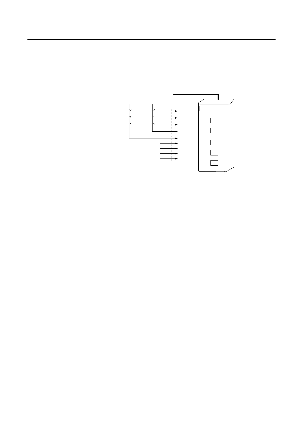
The D-sub 9 pin connector on the rear panel connects the 3260A Series High Power
Electronic Load to the PRODIGIT mode 9931 remote controller and to replace the RECALL
option key 1 to 5 on the front panel of 3260A Series High Power Electronic Load.
9 Pin to 9 Pin 1.5M Cable
4
5
STORE
1
2
3
NC
NC
NC
NC
D-sub 9 Pin
1
2
3
4
5
6
7
8
9
PRODIGIT
PRODIGIT
PRODIGITPRODIGIT
INSTRUMENT PROFESSIONAL
9931
REMOTE INTERFACE
1
2
3
4
5
Fig.2-4 Diagram of Remote Control Port
Page 19
PRODIGIT 3260A Series Operation Manual 13
Chapter 3 Manual Operation
This Chapter deals with the front panel manual operation of 3260A Series High Power Electronic
Load. With regard to calibration procedures, please refer to 3260A Series High Power Load
Calibration Manual. With regard to the control of GPIB/RS-232C control, please refer to Chapter 4
GPIB/RS-232C Remote Operation.
3-1 Description of Front Panel
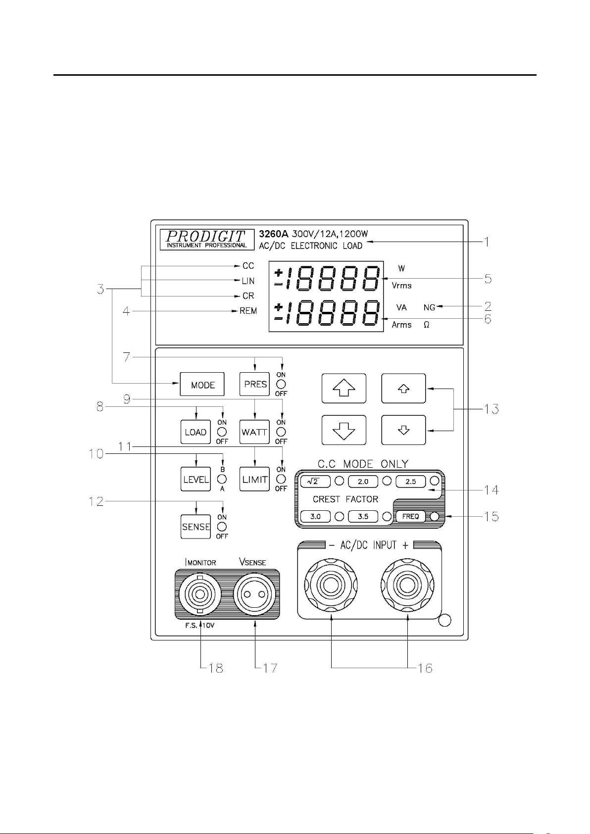
Fig.3-1 Front Panel of 3260A Series High Power Electronic Load
Page 20

14 PRODIGIT
3.1.1 3260A 300V/12A, 1200W AC/DC Electronic Load
3.1.2 NG LED Indicator
3.1.3 MODE Key and LED indicator of CC, LIN, CR
3.1.4 REM LED Indicator
3.1.5 Upper 4-1/2 Digit Monitor
Refers to model number, voltage, current and power specification of 3260A Series
High Power AC/DC Electronic Load.
When the reading of Vmeter, Ameter, wattmeter or VA meter exceeds the upper or
lower limit set, this indicator will display.
On the 3260A Series High Power Electronic Load, there are two working modes
which can be selected by MODE KEY with the sequence of C.C., Linear C.C. and
C.R., then switching can be made in such a sequence. However, LED indicator of CC,
LIN, CR will display the working mode selected.
When 3260A Series High Power Electronic Load is connected with computer
program for control and operation, REM LED Indicator will come on. In such a case,
panel manual operation will become null and void. When REM LED indicator comes
off, panel manual operation will resume.
This 4-1/2 Digit Monitor is a multi-function monitor. Its functions are described as
follows:
3.1.5.1 Under general conditions:
This monitor will be a 4-1/2 digit voltmeter to display the voltage at the load
input end or Vsense BNC input end.
3.1.5.2 Under WATT ON condition:
This monitor will be a 4-1/2 digit wattmeter to display the power of the load.
3.1.5.3 Under LIMIT ON condition:
This monitor will display the upper limit of the voltmeter, Ameter, wattmeter
and VA meter. Its displaying sequence is as follows:
3.1.5.3.1 Display the upper limit of voltmeter with the unit as〝Vrms〞.
3.1.5.3.2 Display the upper limit of ammeter with the unit as〝Arms〞.
3.1.5.3.3 Display the upper limit of wattmeter with the unit as〝W〞.
3.1.5.3.4 Display the upper limit of VA meter with the unit as〝VA〞.
3.1.5.4 Upon protection conditions:
For over-voltage protection, monitor displays〝oVP〞.
3.1.5.5 Under FREQ ON condition:
The monitor will display EfEq, bAn, Sync function settings, its displaying
sequence is as follows:
3.1.5.5.1 Under frequency setting function, monitor displays〝FrEq〞.
3.1.5.5.2 Under Bank selection function, monitor displays〝bAn〞.
3.1.5.5.3 Under SYNC selection function, monitor displays〝Sync〞.
Page 21

PRODIGIT 3260A Series Operation Manual 15
3.1.6 Lower 4-1/2 Digit Monitor
3.1.6.1 Under Preset OFF condition:
This monitor will be a 4 1/2 digit ammeter to display the load current
actually flowing into the electronic load.
3.1.6.2 Under Preset ON conditioin:
This monitor can display the set value of the front panel manual operation
or the set value upon remote control.
3.1.6.2.1 Display the set value of C.C. Level A and B under C.C.mode
with the unit as〝Arms〞.
3.1.6.2.2 Display the set value of C.R. Level A and B under C.R. mode
with the unit as〝Ω.〞
3.1.6.2.3 Upon protection condition:
Upon over-current, over-power and over-temerature,〝oCP〞,
〝oPP〞and〝oTP〞will be displayed respectively.
3.1.6.3 Under LIMIT ON condition:
3.1.6.3.1 Display the lower limit of voltmeter with the unit as〝Vrms〞.
3.1.6.3.2 Display the lower limit of ammeter with the unit as〝Arms〞.
3.1.6.3.3 Display the lower limit of Wattmeter with the unit as〝W〞
3.1.6.3.4 Display the lower limit of VA meter with the unit as〝VA〞.
3.1.6.4 Under REEQ ON condition:
3.1.6.4.1 Under frequency setting function, monitor will display DC , 0.1~
400.0 Hz.
3.1.6.4.2 Under bank selection function, monitor will display 0~10.
3.1.6.4.3 Under sync selection function, monitor will display 〝ON 〞,
〝OFF〞.
3.1.7 PRES ON/OFF Key and LED Monitor
Depressing PRES Key will be ON, further depressing will be OFF, further depressing
will be ON again and so on. ON means Preset ON, e.g., to preset condition display to
ON. OFF means preset OFF, e.g., the condition is not preset and shall be the actual
condition of the voltage and current of the load.
Under Preset OFF condition, the upper 4 1/2 digit monitor displays the voltage input
to electronic load while the lower 4 1/2 digit monitor displays the current flowing into
electronic load with the unit as〝Vrms〞&〝Arms〞respectively and the unit indicator
will come on also.
Under Preset ON condition, PRES LED monitor is ON, both upper and lower 4 1/2
digit monitors will have different displays with the change of working mode as shown
below:
3.1.7.1 C.C.Mode:
The setting value of Level A / B load current can be displayed on the lower
4 1/2 digit monitor with the unit as〝Arms〞, LED indicator will be ON.
3.1.7.2 Linear C.C. Mode:
The setting value of Level A / B load current can be displayed on the lower
4 1/2 digit monitor with the unit as〝Arms〞, LED indicator will be ON.
3.1.7.3 C.R.Mode:
The setting value of Level A/B load resistance can be displayed on the
lower 4 1/2 digit monitor with the unit as〝Ω〞, LED indicator will be ON.
Page 22

16 PRODIGIT
3.1.8 Load ON/OFF Key and LED Indicator
Whether or not the electronic load input end of 3260A series High Power is loaded
with current can be controlled by Load ON/OFF Key. Under Load OFF condition and
upon Load ON, the electronic load of 3260A series High Power will return to the load
condition set originally and Load LED is ON indicating that the electronic load is at
present under Load ON condition and is ready at any time to be loaded with the load
current of the AC/DC input power source.
! CAUTION 。。。。Turn off the load when applying the output of the equipment under test to the
3260A series load. Then, turn the load on. If you are making the connection with the
load turned on, be sure to turn off the output of equipment under test.
If a relay or electromagnetic switch is inserted between the load input connector and
the output connector of the equipment under test, turn on the relay or
electromagnetic switch when the load is turned off. Then, turn the load on.
。。。。If you are repeating the operation of turn on/off the output of the equipment under
test when using the 32611A series load, turn on the output only after the load input
terminal voltage reaches approximately 0V after turning off the output. If you do not,
the internal bias power supply stays off, and the specified current may not be
supplied.
3.1.9 Watt ON/OFF Key and LED Indicator
Depressing Watt Key will be ON, further depressing will be OFF, further depressing
will be ON again and so on. ON means Watt ON, e.g., to indicate the Watt VA
condition of actual loading. OFF means Watt OFF, e.g., to indicate the voltage and
current condition of actual loading.
3.1.9.1 Under Preset OFF condition, the upper 4 1/2 digit monitor displays the
Watt consumed for electronic loading while the lower 4 1/2 digit monitor
displays the VA flowing into electronic load with the unit as〝W〞,〝VA〞
respectively and the unit indicator will come on.
3.1.9.2 Under Preset ON condition, both upper and lower 4 1/2 digit monitors will
have different displays with the change of working mode as shown below:
3.1.9.2.1 C.C.Mode:
The setting value of Level A/B load current can be displayed on
the lower 4 1/2 digit monitor with the unit as〝Arms〞and LED
indicator will come on.
3.1.9.2.2 Linear C.C. Mode:
The setting value of Level A/B load current can be displayed on
the lower 4 1/2 digit monitor with the unit as〝Arms〞and LED
indicator will come on.
3.1.9.2.3 C.R.Mode:
The setting value of Level A/B load resistance can be displayed
on the lower 4 1/2 digit monitor with the unit as〝Ω〞and LED
indicator will be ON.
Page 23

PRODIGIT 3260A Series Operation Manual 17
3.1.10 Level A/B Key and LED Monitor
Depressing Level Key will be B , further depressing will be A, further depressing will
be B again and so on. B means Level B (LED ON), e.g., to move out Level A, then
move in Level B. A means Level A (LED OFF), e.g., to move out Level B, then move
in Level A.
Under the condition of setting Memory A or B, this key is mainly for setting the values
of groups A/B for rapid switching load current or resistance.
3.1.11 Limit ON/OFF Key and LED indicator
Being depressed, LED will come on and in LIMIT ON condition:
3.1.11.1 Both upper and lower 4-1/2 digit monitors display the upper and lower limit
of the voltmeter with the unit as〝Vrms〞.
3.1.11.2 Both upper and lower 4-1/2 digit monitors display the upper and lower limit
of the ammeter with the unit as〝Arms〞.
3.1.11.3 Both upper and lower 4-1/2 digit monitors display the upper and lower limit
of the watt meter with the unit as〝W〞
3.1.11.4 Both upper and lower 4-1.2 digit monitors display the upper and lower limit
of the VA meter with the unit as〝VA〞
When depressing is made to five time, LED will come off and in Limit OFF
condition. Please refer to 3.1.13.2 for upper and lower limit adjustment.
3.1.12 SENSE ON/OFF Key and LED Indicator
The voltmeter and internal trigger circuit of 3260A Series High Power Electronic Load
can be controlled by this Key thus determining whether or not the input to the
voltmeter is made from the AC input end (OFF) or Vsense end (ON). Upon Vsense
ON, LED indicator will be ON and the 4-1/2 digit voltmeter can display the voltage
read from Vsense. Upon Vsense OFF, the 4-1/2 voltmeter can display the voltage
read from AC input end.
3.1.13 Load Current Rough Tuning/Fine Tuning, Up/Down Key
3.1.13.1 Under usual or PRESET Light Lit Condition:
3.1.13.1.1
3.1.13.1.2 :Set Value Fine Tuning Up/Down Key.
3.1.13.2 Upon LIMIT Light ON:
3.1.13.2.1 :Upper limit value Up/Down Key.
3.1.13.2.2 :Lower limit value Up/Down Key.
3.1.13.3 Upon FREQ light ON:
3.1.13.3.1 FrEq: is freq. Rough Tuning Up/Down Key is freq.
3.1.13.3.2 bAn: is Fine Tuning Up Key is Fine Tuning Down
3.1.13.3.3 Sync: is ON Key is OFF Key.
3.1.14 √2, 2.0, 2.5, 3.0, 3.5 Key and LED indicator.
This key only functions upon C.C. mode and all LED off upon Linear C.C. mode and
C.R. mode.
These keys are used to change the current C.F. (Peak Factor) of C.C. mode.
However, in change of BANK, these keys will define different C.F. values.
:Set Value Rough Tuning Up/Down Key.
Fine Tuning Up/Down Key.
Key.
Page 24
18 PRODIGIT
3.1.15 FREQ Key and LED indicator
3.1.16 AC/DC Load Input Connector
3.1.17 Vsense BNC, Voltage Sensing Input BNC Connector.
C.C. mode: After depressing, LED will come on, the first depressing shows FREQ,
further depressing shows BANK (No such function for DC), another
pressing shows SYNC, depressing again will be off.
Linear C.C. and C.R. mode: LED will come on, the first depressing shows FREQ,
depressing again will be off.
For the following items, except for 3.1.15.3,
3.1.15.1 FREQ (For Frequency Setting) : Setting Range: DC , 0.1~400.0 Hz.
3.1.15.1 BANK (For Bank Setting ) : 0~10 totaling 11 banks (This function will be
invalid for DC).
3.1.15.3 SNYC (Current Bank Sync Signal Selection):
ON is external Sync, OFF is internal Sync.
When Load Input Connector is used, be sure that the rated specification of the
voltage and current of the 3260A Series High Power Electronic Load shall not be
exceeded. Upon wiring, please refer to 3.4 lest the internal circuit and connector
should be damaged.
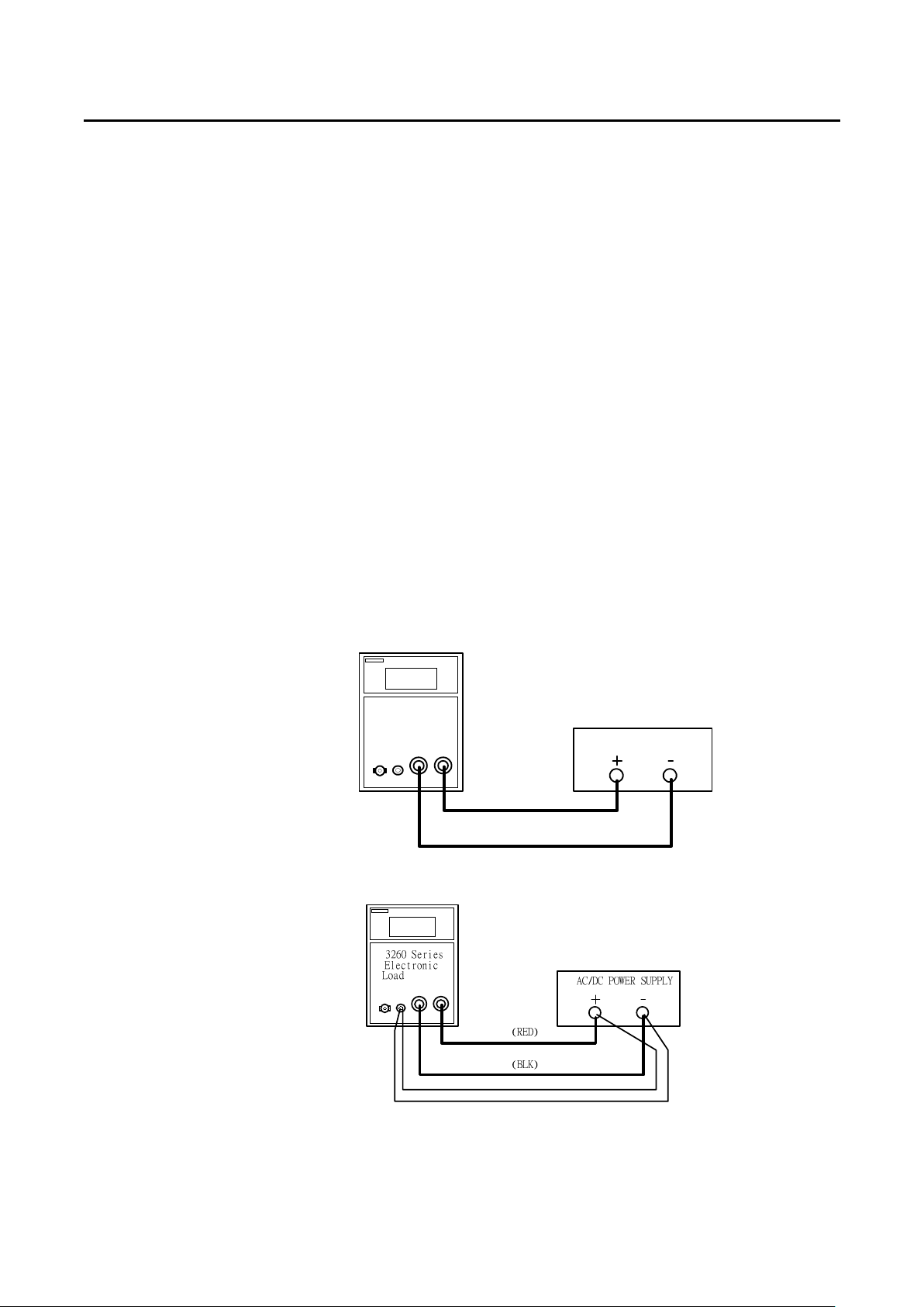
In order to solve the voltage drop of the conductor under the condition of big load
current, Vsense-CLIP cable can be used to connect with the specific point to be
measured thus obtaining the specific voltage value. Please refer to the application
information of Fig.3-2.
3260 Series
Electronic
Load
AC/DC POWER SUPPLY
(RED)
(BLK)
Connecting Method under small load current condition
Connecting Method under small load current condition
Fig.3-2 Typical Way for Connecting 3260A Series High Power Electronic Load
Page 25
PRODIGIT 3260A Series Operation Manual 19
3.1.18 Imonitor Current Monitoring output BNC Connector
Imonitor output signal is designed mainly to facilitate connection with the oscillograph
so that the waveform of the load current can be observed. Regardless of Preset ON
or OFF, the analog signal output from Imonitor is in direct proportion with the load
current flowing through the load current. Please refer to the relationship between the
analog voltage output signal and load current of 3260A Series High Power Electronic
Load listed in Table 3-1. The full scale of Imonitor is 10V.
The Imonitor BNC output signal in 3260A Series High Power Electronic Load is
through an isolated amplifier, e.g., the earth potential of the output analog signal and
the earth potential of the DC load input are separated with each other. In this way,
when connection is made with the oscillograph of which another input is connected
with both ends of the load, the metering error shall not be resulted from the negative
end of the Imonitor BNC output flowing to the negative end via the oscillograph due
to different potential. On the other hand, When the positive and negative power
source is measured and the two load current wave forms are observed at the same
time, two sets of Imonitor can be connected with Ch1 and Ch2 of the oscillograph.
As the general input of the oscillograph has no isolated insulation device, therefore, if
the Imonitor output has no isolated insulation device after connection is made, shortcircuit will happen to the power source to be measured thus disabling the measuring.
This is because the Imonitor output of the general electronic load shares the same
reference point with the earth of the load input. However, as a light insulation isolated
amplifier is contained in the 3260A Series High Power Electronic Load, the condition
cited above can be avoided, e.g., the load current wave form of two sets of positive
and negative power sources to be measured can be observed simultaneously without
causing any affection or inconvenience.
Imonitor
Imonitor
3260A 3261A 32611A 32612A 32613A 32614A
3 A/V 4.5 A/V 9 A/V 13.5 A/V 18 A/V 22.5 A/V
32615A 32616A
27 A/V 31.5 A/V
Table 3-1 3260A Series High Power Electronic Load Imonitor Specification
Page 26

20 PRODIGIT
3-2 STORE / RECALL operation
The six function keys on the front panel of 3260A Series High Power Load are designed for
high testing throughput purpose. There are five operation states or testing steps can be store
in the non-volatile memory of 3260A series electronic load, each state can save or recall the
load status and level for four 3260A series Electronic load simultaneously.
3.2.1 STORE procedure:
3.2.1.1 Set the load status and load level from load module respectively.
3.2.1.2 Press the STORE key on the 3260A front panel, the STORE LED
annunciator is flashing. (about two times every second)
3.2.1.3 Press one of the state 1-5 key, the appropriate state key's LED annunciator
will be lit immediately, the load level and status of 3260A series load
module is stored into the non-volatile memory this time. The STORE LED
annunciator turns to OFF, it means the STORE procedure is completed.
Note:
1. After press the STORE key, the STORE LED annunciator will flash for 10
seconds, if the STATE 1-5 key is not pressed within this 10 seconds, the STORE
LED annunciator will be OFF, it indicated the STORE process is not available now,
please repeat the STORE procedure for a new STORE operation.
2. After press the STORE key, then press the STORE key, then press the STORE
LED annunciator will be blank, it indicate the STORE process is not available.
3. After press the STORE key, it is available and useful to operate the front panel
key on the 3260A series Electronic load However, the STATE LED will be OFF if
any key on front panel is operated, this indicates the front panel state of 3260A
series is not the same as STORE state.
3.2.2 STORE function:
It can store up to states of 3260A series load setting simultaneously, if you store 2
different states in the same state key, the later state will overcome the previous state,
it acts as update the new data.
3.2.3 RECALL operation:
Press one of the state 1 through 5 key, the appropriate LED annunciator will be lit,
the store state on the 3260A Series High Power Load is sending to control unit
simultaneously. Before press the states key, you press any key on the front panel
then the state LED annunciator is blank immediately, it indicates the STORE state
has been changed by read judgement on front panel.
Page 27
PRODIGIT 3260A Series Operation Manual 21
Press Exit key
Serie high ower electronic
3-3 AUTO SEQUENCE testing function description
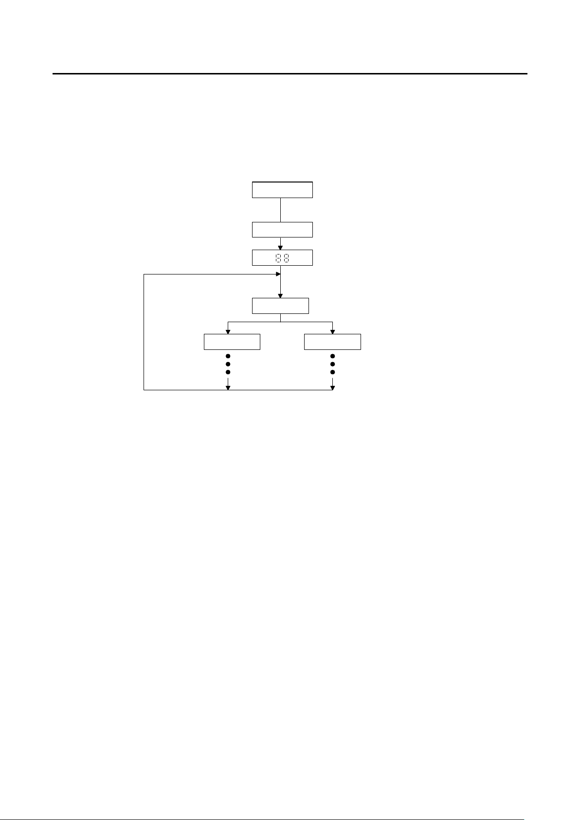
There are two modes in AUTO SEQUENCE function, EDIT MODE and TEST MODE, The
AUTO SEQ mode can be entered by press S3 + S4 key simultaneously, then press STORE
key again to enter the EDIT MODE, or press START key to enter the TEST MODE, Please
refer to the flow chart operation below:
Show r1-r9
Display 3260
Firmware version r1-r9
Press STORE key
3.3.1 EDIT MODE
The TEST Mode of Auto-Sequence function is entered by press S3 + S4 key
simultaneously, The EDIT mode of Auto Sequence function is entered by press S3 +
S4 key simultaneously, the S3 and S4 LED are ON to indicate Auto-sequence mode,
then the Edit mode of Auto-sequence function is proceed by press STORE key.
The EDIT MODE flow chart is described below:
3.3.1.1 There are nine Auto Sequence (n1-n9) can be edit within 3260A Series
3.3.1.2 Each Auto Sequence has up to 16 Test step, where each step is any one
memory of 5 sets Store memory
3.3.1.3 Each test step has t1 (test time) and t2 (delay time), the unit is 100mS, the
range is 0.1S - 9.9S in 100mS resolution. 3260A series load mainframe will
check each module GO/NG at the end of t1 (test time), the next step will be
started after duration t2 (delay time).
3.3.1.4 The test step sequence can be up to 16 step, and can be terminated by
press EXIT key if less than 16 step is required.
bn
Press S3+S4 key
AUTO SEQ.
STORE MODE
Normal Mode
Display bank
Display bank no.
Show n1~n9
Press STATE key
STATE MODE
Fig.3-3 AUTO SEQ function operation flow chart
Page 28
22 PRODIGIT
Exit
Press Exit key
S3+S4
Show n1-n9
Initial=n1~n9
Press Store
Store Mode
Show SP= 0
1.Press S3+S4 key
2.Show AUTO SEQ. No.1-No.9,
Press Up/Down key to set n1-n9
3.Press Store key to Store Mode
Sp = 0 ~ F(16 step)
Press Exit key
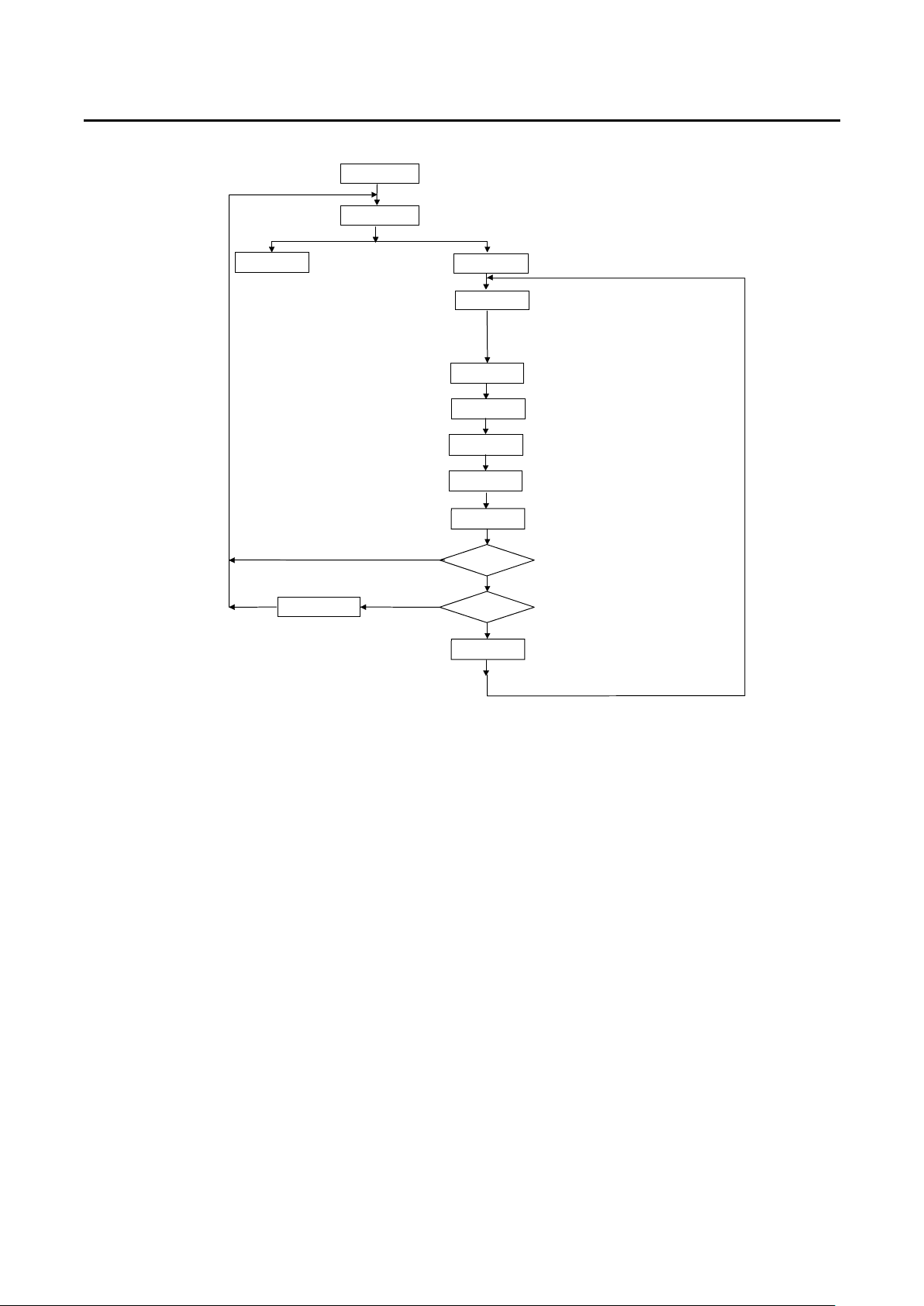
Fig.3-4 STORE (EDIT) MODE OPERATIONO FLOW-CHART
3.3.2 TEST MODE
The TEST Mode of Auto-Sequence function is entered by press S3 + S4 key
simultaneously, the S3 and S4 LED are ON to indicate Auto-sequence mode, then
the Test mode of Auto-sequence function is proceed by press START key.
The TEST MODE flow chart is described below:
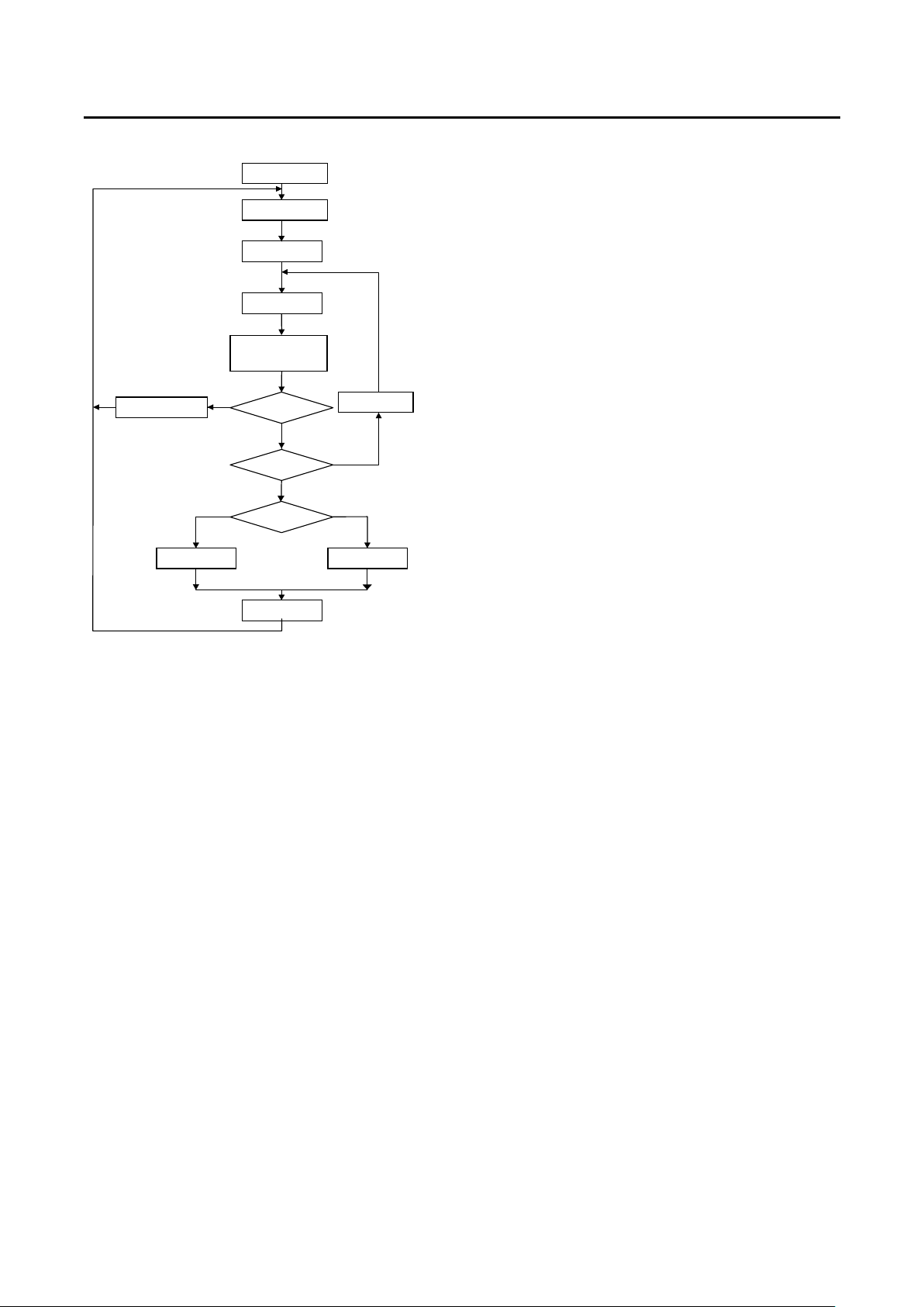
3.3.2.1 After press START key, the 3260A series load controls all the module
within the mainframe to recall correspond memory which had been stored
in Auto-sequence (n1~n9) memory.
3.3.2.2 The sequence start from (Step 0 - t1 - t2), then (step 1 - t1 - t2), and so on
until last step or stop by press EXIT key.
3.3.2.3 The two digit LED display will show GO (flash) if all the test in all module is
pass, and will show nG (flash) if there is at least one failure during the test.
3.3.2.4 User can press Start key to continue another test, or the 3300C can quit
from Auto-Sequence mode by press EXIT key.
Yes
Yes
Set State
Show t1
Set T1
Show t2
Set T2
Step = F?
End?
Sp=Sp+1
Set State No.1~5
Press Store key to next item
When press Store key, LED show t1
Press Up/Down key to set T1,
t1 = 01-99, Unit = 100mS
Press Store key to next item
When press Store key, LED show t2
Press Up/Down key to set T2,
t1 = 00-99, Unit = 100mS
Press Store key to next item
Is last step (16 step)?
Page 29
PRODIGIT 3260A Series Operation Manual 23
EXI
S3+S4
1.Press S3+S4 key, and S3 and S4 LED are ON
Press Exit key
Show GO
Show n1-n9
Start Mode
Testing
Show Memery
bank and State
Yes
End?
PASS
PASS/FAIL
4.2 4.3
Any key
1
2
3
Sp = Sp+1
No
4
No
Yes
FAI
Show NG
Fig.3-5 TEST MODE OPERATION FLOW-CHART
Initial = n1
4.1
2.Show AUTO SEQ. No.1-No.9,
Press Up/Down key to set n1-n9
3.Press Start key to Start Mode
Press Start key
1.To recall correspond memory which had been stored in n1-n9 memory
2.Check the GO/NG indicator
3.Press Exit key to quit the AUTU SEQ mode
4.If test is GO, than step is last?
4.1 If no than Step + 1, continue another step.
4.2 If "Yes", than if all the test in all module is pass,
Show GO.
4.3 If "Yes", than if there is at least one failure during the test,
Show NG.
Page 30
24 PRODIGIT
3-4 Setting of Freq. & Selection of Bank & Sync.
3.4.1 Frequency Setting:
The range for setting the frequency of 3260A Series High Power AC/DC Electronic
Load is from DC , 0.1 ~ 400.0 Hz.
The authorization for setting the frequency of 3260A Series High Power AC/DC
Electronic Load is the frequency output by U.U.T. Upon completion of setting, the
SYNC trigger setting has to be set to OFF and the setting value of such a frequency
will be valid. If the frequency setting is less than 40 Hz, the frequency setting value
shall be set automatically to DC.
3.4.2 Bank Selection:
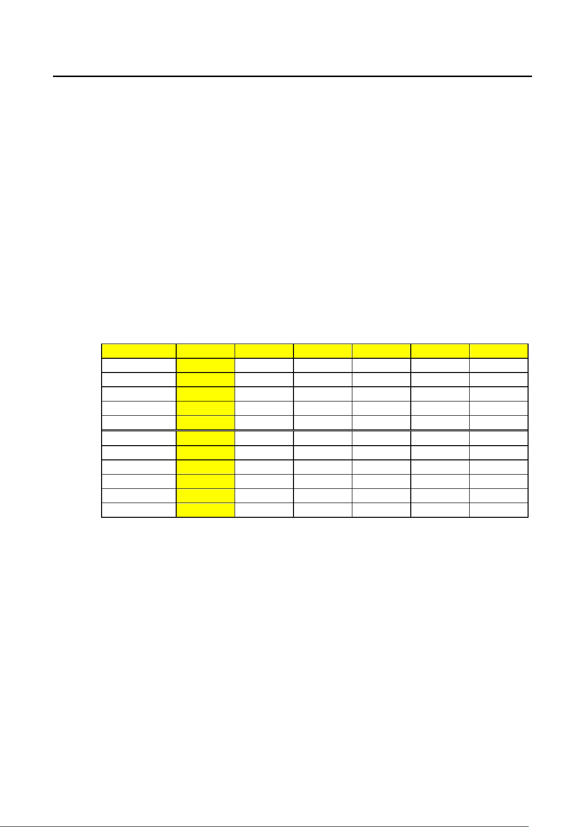
3260A Series High Power AC/DC Electronic Load provides 11 built-in sets totaling 55
wave form information. The content of Bank is as shown in Table 3-2. Please refer to
Appendix for details.
Note: When Frequency is set to DC, the wave form information shall be fixed at DC level,
also, this Bank selection function will not be provided until after Frequency is set to
AC.
BANK A B C D E
SINE WAVE
1 1.5 1.6 1.7 1.8 1.9
2 3.0 3.1 3.2 3.3 3.4
C.F.= 2.0 3 P.F.=-0.85 P.F.=-0.80 P.F.=-0.75 P.F.=-0.70 P.F.=-0.65
C.F.= 2.5 4 P.F.=-0.70 P.F.=-0.65 P.F.=-0.60 P.F.=-0.50 P.F.=-0.40
C.F.= 3.5 5 P.F.=-0.50 P.F.=-0.45 P.F.=-0.40 P.F.=-0.35 P.F.=-0.30
C.F.= 2.0 6 P.F.=0.85 P.F.=0.80 P.F.=0.75 P.F.=0.70 P.F.=0.65
C.F.= 2.5 7 P.F.=0.70 P.F.=0.65 P.F.=0.60 P.F.=0.50 P.F.=0.40
C.F.= 3.5 8 P.F.=0.50 P.F.=0.45 P.F.=0.40 P.F.=0.35 P.F.=0.30
Square Wave
DC 10 √2dc 2dc 2.5dc 3.0dc 3.5dc
0 √2 2.0 2.5 3.0 3.5
9 1 1.1 1.2 1.3 1.4
Table 3-2 3260A Built-In Wave Form Data Bank
Page 31
PRODIGIT 3260A Series Operation Manual 25
3.4.3 SYNC Selection:
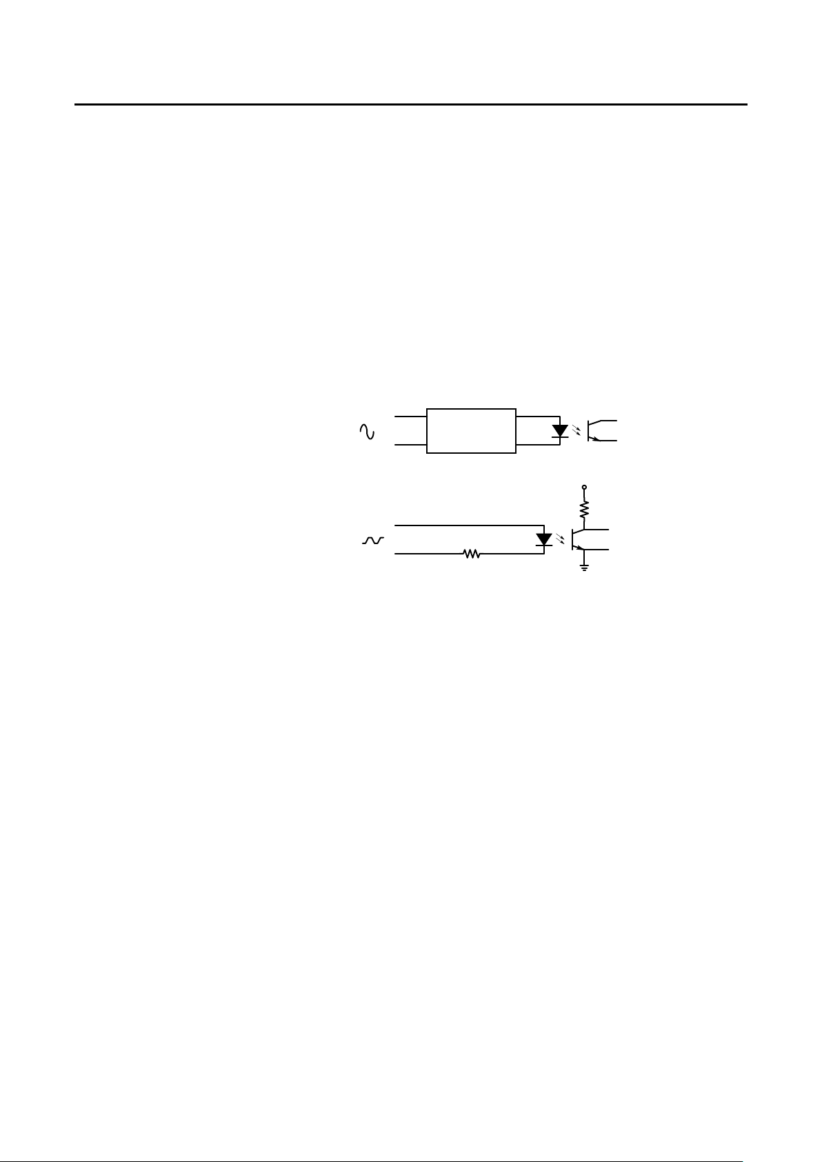
3.4.3.1 Exterior SYNC Signal(SYNC ON)
The user can input a SYNC signal to the Analog Programming Input BNC
terminal of the back plate of 3260A. Based on this exterior SYNC signal,
3260A Series High Power Electronic Load can be conversed to SYNC
trigger signal via internal isolated circuit thus controlling the SYNC of the
load current and voltage, in other words, the phase of load current will vary
with SYNC trigger signal.
Note:The SYNC signal input from exterior must be the signal of which the
duty cycle is 50%.
3.4.3.2 Internal SYNC signal(SYNC OFF):
The internal SYNC signal source of 3260A Series High Power Electronic
Load is taken from the signal at the end of input connector for generating
current SYNC signal via internal zero crossing circuit and isolation circuit.
EXT+
EXT-
Input
Zero Crossing
SYNC "OFF"
330Ω
SYNC "ON"
SYNC
+5V
SYNC
Fig.3-6 Description of Sync.
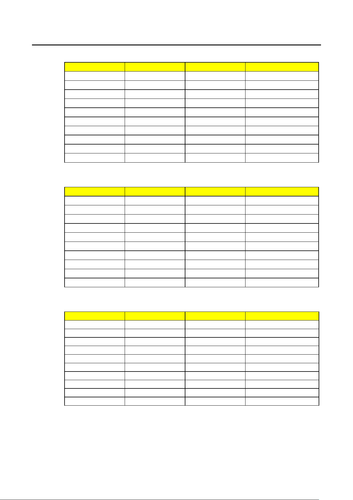
3-5 Initial setting parameter of 3260A Series High Power Electronic
Load
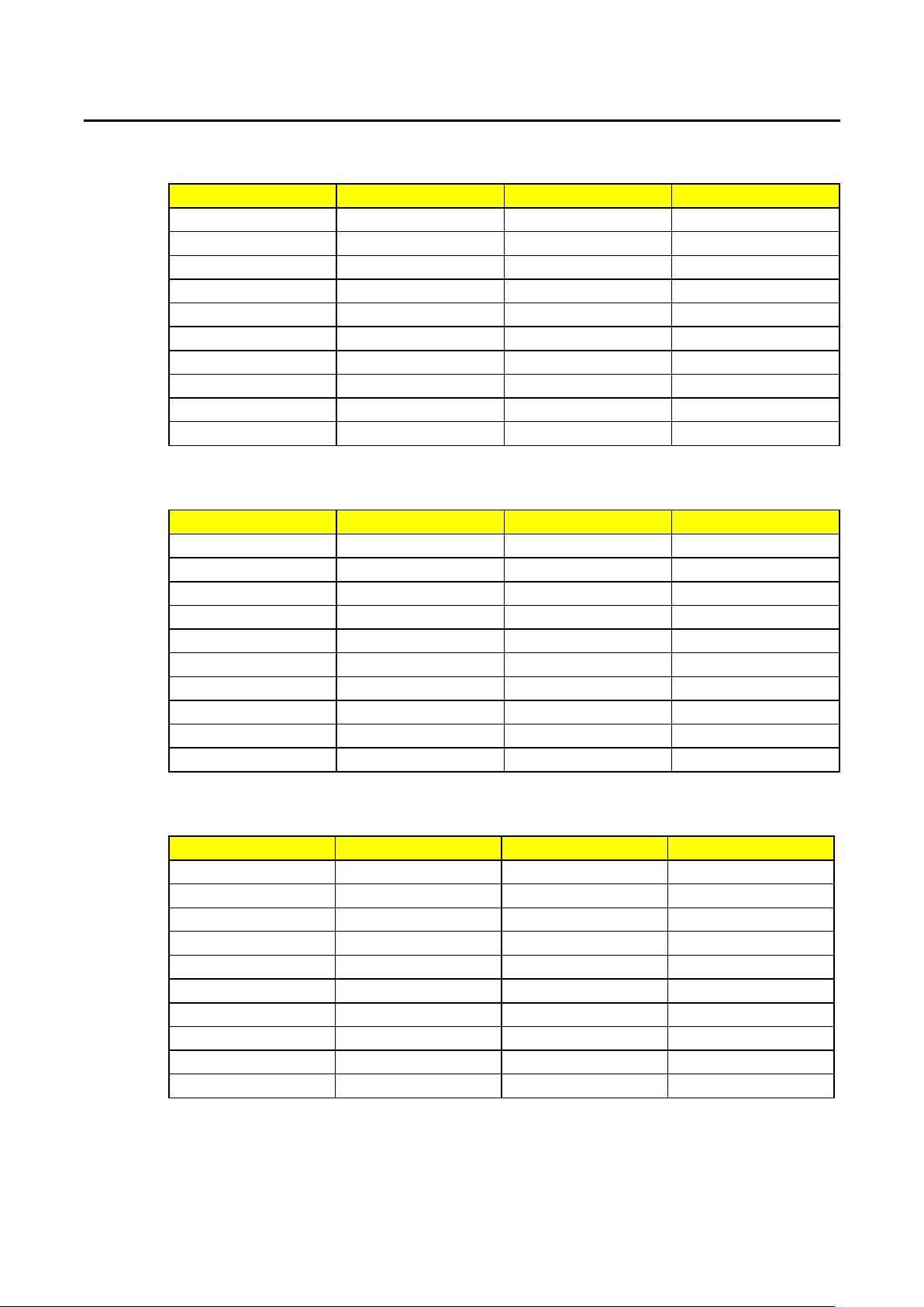
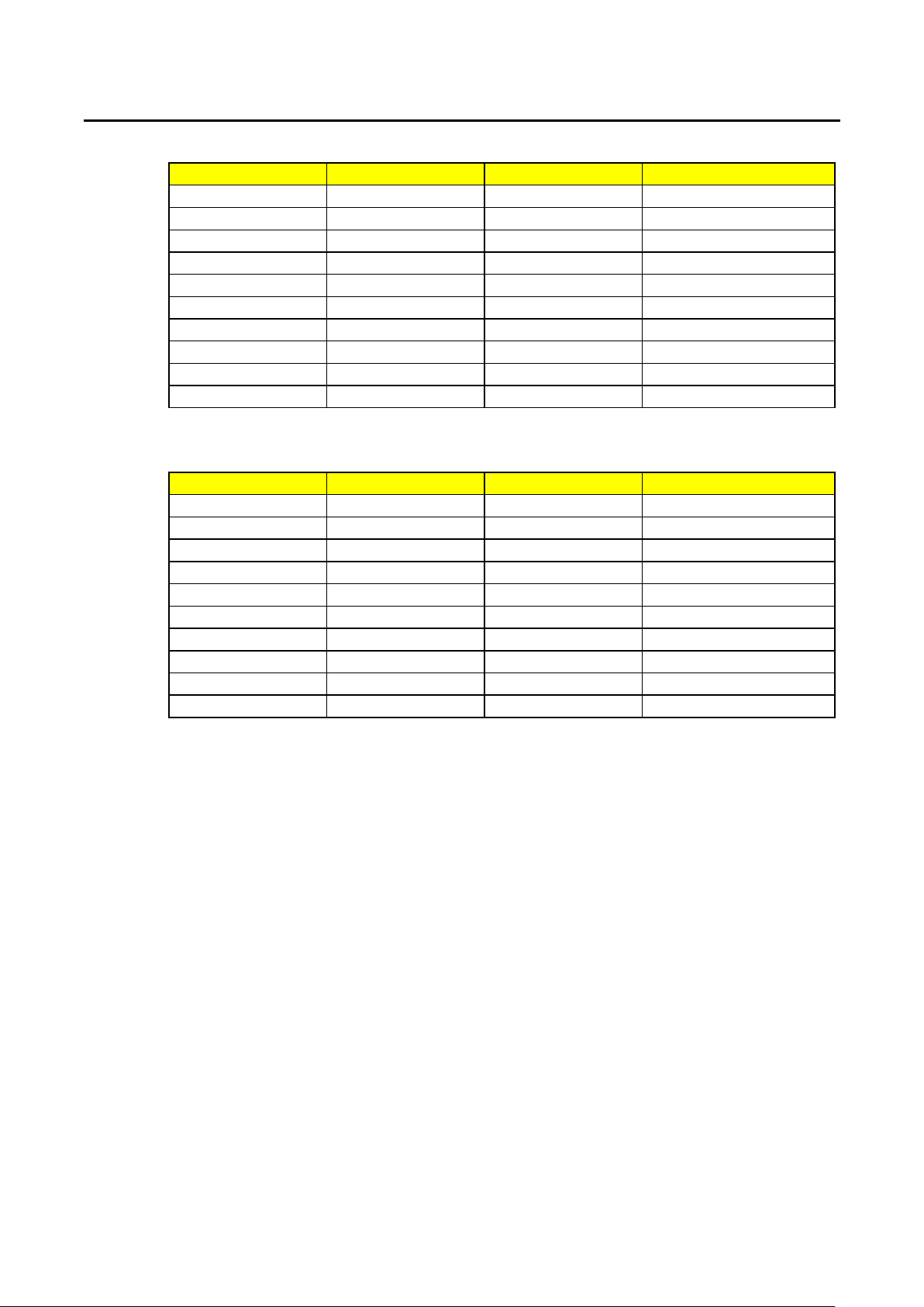
The initial setting parameters of 3260A Series High Power Electronic Load are described
from Table 3-3 to 3-11 respectively.
3.5.1 Last Setting
All 3260A Series High Power Electronic Loads have the function for simplifying the
setting procedures. This function is called〝Last Setting〞e.g., All 3260A Series High
Power Electronic Load, undergone the initial inspection program procedure (Power
on), can be immediately changed back to the setting condition prior to Machine OFF
thus simplifying the procedures for re-setting after machine being turned off.
3.5.2 Reset
If the memory data of 3260A Series High Power Electronic Load has been sabotaged,
for example, unstable power source or noises will result in possible error of
information in NVRAM (such as the indication on the front panel is different from the
actual condition), under such a case, reset shall be made to correct the errors.
For reset of 3260A Series High Power Electronic Load,〝SENSE〞and〝PRES〞
button shall be depressed simultaneously. In such a case, the front panel monitor will
display model number and edition repeatedly and initialize the setting parameter of
3260A Series High Power Electronic Load as shown in Tables 3-3 ~ 3-10 until the
Page 32
26 PRODIGIT
button is released.
Description Condition/Value Description Condition/Value
MODE CC C.F. √2
LOAD OFF FREQ FREQ = 60.0Hz
LEVEL A BANK = 0
SENSE OFF SYNC = OFF
PRES OFF CC LEVEL A 0.000A
WATT OFF CC LEVEL B 0.000A
LIMIT V
A
W
VA
LIMIT
= 400.0V LIN LEVEL A 0.000A
LIMIT
= 20.00A LIN LEVEL B 0.000A
LIMIT
= 2000.0W CR LEVEL A 80E3Ω
LIMIT
= 2000.0W CR LEVEL B 80E3Ω
Table 3-3 3260A Initial Condition Setting
Description Condition/Value Description Condition/Value
MODE CC C.F. √2
LOAD OFF FREQ FREQ = 60.0Hz
LEVEL A BANK = 0
SENSE OFF SYNC = OFF
PRES OFF CC LEVEL A 0.000A
WATT OFF CC LEVEL B 0.000A
LIMIT V
A
W
VA
LIMIT
= 400.0V LIN LEVEL A 0.000A
LIMIT
= 20.00A LIN LEVEL B 0.000A
LIMIT
= 2000.0W CR LEVEL A 53E3Ω
LIMIT
= 2000.0W CR LEVEL B 53E3Ω
Table 3-4 3261A Initial Condition Setting
Description Condition/Value Description Condition/Value
MODE CC C.F. √2
LOAD OFF FREQ FREQ = 60.0Hz
LEVEL A BANK = 0
SENSE OFF SYNC = OFF
PRES OFF CC LEVEL A 0.000A
WATT OFF CC LEVEL B 0.000A
LIMIT V
A
W
VA
LIMIT
= 400.0V LIN LEVEL A 0.000A
LIMIT
= 40.00A LIN LEVEL B 0.000A
LIMIT
= 4000.0W CR LEVEL A 26E3Ω
LIMIT
= 4000.0W CR LEVEL B 26E3Ω
Table 3-5 32611A initial Condition Setting
Page 33
PRODIGIT 3260A Series Operation Manual 27
Description Condition/Value Description Condition/Value
MODE CC C.F. √2
LOAD OFF FREQ FREQ = 60.0Hz
LEVEL A BANK = 0
SENSE OFF SYNC = OFF
PRES OFF CC LEVEL A 0.000A
WATT OFF CC LEVEL B 0.000A
LIMIT V
A
W
VA
LIMIT
= 400.0V LIN LEVEL A 0.000A
LIMIT
= 60.00A LIN LEVEL B 0.000A
LIMIT
= 6000 W CR LEVEL A 17776Ω
LIMIT
= 6000 W CR LEVEL B 17776Ω
Table 3-6 32612A initial Condition Setting
Description Condition/Value Description Condition/Value
MODE CC C.F. √2
LOAD OFF FREQ FREQ = 60.0Hz
LEVEL A BANK = 0
SENSE OFF SYNC = OFF
PRES OFF CC LEVEL A 0.000A
WATT OFF CC LEVEL B 0.000A
LIMIT V
A
W
VA
LIMIT
= 400.0V LIN LEVEL A 0.000A
LIMIT
= 80.00A LIN LEVEL B 0.000A
LIMIT
= 8000 W CR LEVEL A 13333Ω
LIMIT
= 8000 W CR LEVEL B 13333Ω
Table 3-7 32613A initial Condition Setting
Description Condition/Value Description Condition/Value
MODE CC C.F. √2
LOAD OFF FREQ FREQ = 60.0Hz
LEVEL A BANK = 0
SENSE OFF SYNC = OFF
PRES OFF CC LEVEL A 00.00A
WATT OFF CC LEVEL B 00.00A
LIMIT V
A
W
VA
LIMIT
= 400.0V LIN LEVEL A 00.00A
LIMIT
= 100.00A LIN LEVEL B 00.00A
LIMIT
=10000 W CR LEVEL A 10666Ω
LIMIT
= 10000 W
CR LEVEL B 10666Ω
Table 3-8 32614A initial Condition Setting
Page 34
28 PRODIGIT
Description Condition/Value Description Condition/Value
MODE CC C.F. √2
LOAD OFF FREQ FREQ = 60.0Hz
LEVEL A BANK = 0
SENSE OFF SYNC = OFF
PRES OFF CC LEVEL A 00.00A
WATT OFF CC LEVEL B 00.00A
LIMIT V
A
W
VA
LIMIT
= 400.0V LIN LEVEL A 00.00A
LIMIT
= 120.00A LIN LEVEL B 00.00A
LIMIT
=12000 W CR LEVEL A 8888Ω
LIMIT
= 12000 W
CR LEVEL B 8888Ω
Table 3-9 32615A initial Condition Setting
Description Condition/Value Description Condition/Value
MODE CC C.F. √2
LOAD OFF FREQ FREQ = 60.0Hz
LEVEL A BANK = 0
SENSE OFF SYNC = OFF
PRES OFF CC LEVEL A 00.00A
WATT OFF CC LEVEL B 00.00A
LIMIT V
A
W
VA
LIMIT
= 400.0V LIN LEVEL A 00.00A
LIMIT
= 140.00A LIN LEVEL B 00.00A
LIMIT
= 14000 W
LIMIT
= 14000 W
CR LEVEL A 7616Ω
CR LEVEL B 7616Ω
Table 3-10 32616A initial Condition Setting
Page 35

PRODIGIT 3260A Series Operation Manual 29
3-6 Consideration of Load Input Connector and Connecting Lead Wire
Load Input Connector used for 3260A Series High Power Electronic Load is the 5-purpose
input connector of which the usage is as follows:
3.6.1 Plug Connector:
This is the most common way for connecting the equipment to be measured with
3260A Series High Power Electronic Load. It is recommended that this connector
shall be used when the load current is less than 20A because the rated current of the
plug connector is 20A. Please avoid excess of the rated current to prevent damage
due to overheat. The maximum gauge of the connecting wire is AWG #14.
3.6.2 Hook-Type Terminal
The attachments of 3260A Series High Power Electronic Load include two (2) hooktype terminals for connecting the equipment to be measured with the wire of AC load
input connector of the electronic load. Hook-type terminal can provide the input
connector with good contacting characteristics. It is recommended that the hook-type
terminal can be used for any occasion. The maximum gauge of the connecting wire is
AWG #10.
3.6.3 Lead Wire Insertion Type:
This is the most simple way to insert the connecting wire into the holes on the metal
portion of the input connector. The maximum gauge of the connecting wire is AWG
#14.
3.6.4 Plug Connector and Hook-Type Terminal:
This method can provide higher current rating and lower impedance of the
connecting wire. When input load current is higher than 20A or the connecting lead
wire is longer, this method will be optimum.
3.6.5 Plug Connector and Lead Wire Insert Type:
This method can be used when the input current is higher than 20A or the connecting
lead wire is longer. When the object to be measured is connected with the electronic
load, it is most important that the size of the connecting wire shall be taken into
account. In order to prevent overheat thus maintaining good adjustment rate, the
requirement of minimum size of the connecting wire or minimum size of the wire
gauge shall be met. During actual application, please pay attention to the size of wire
gauge and note that the voltage drop of each connecting wire shall be less than 0.5V.
3.6.6 Connection procedure of the load input terminal:
1. Turn off the POWER switch.
2. Check that the output of the equipment under test is off.
3. Connect the load wire to the load input terminal.
4. Check the polarity of the connection and connect the load wire to the output
terminal of the equipment under test.
Page 36
30 PRODIGIT
3.7 Rough Tuning, Fine Tuning & Increment & Decrement Adjustment
of Load Current.
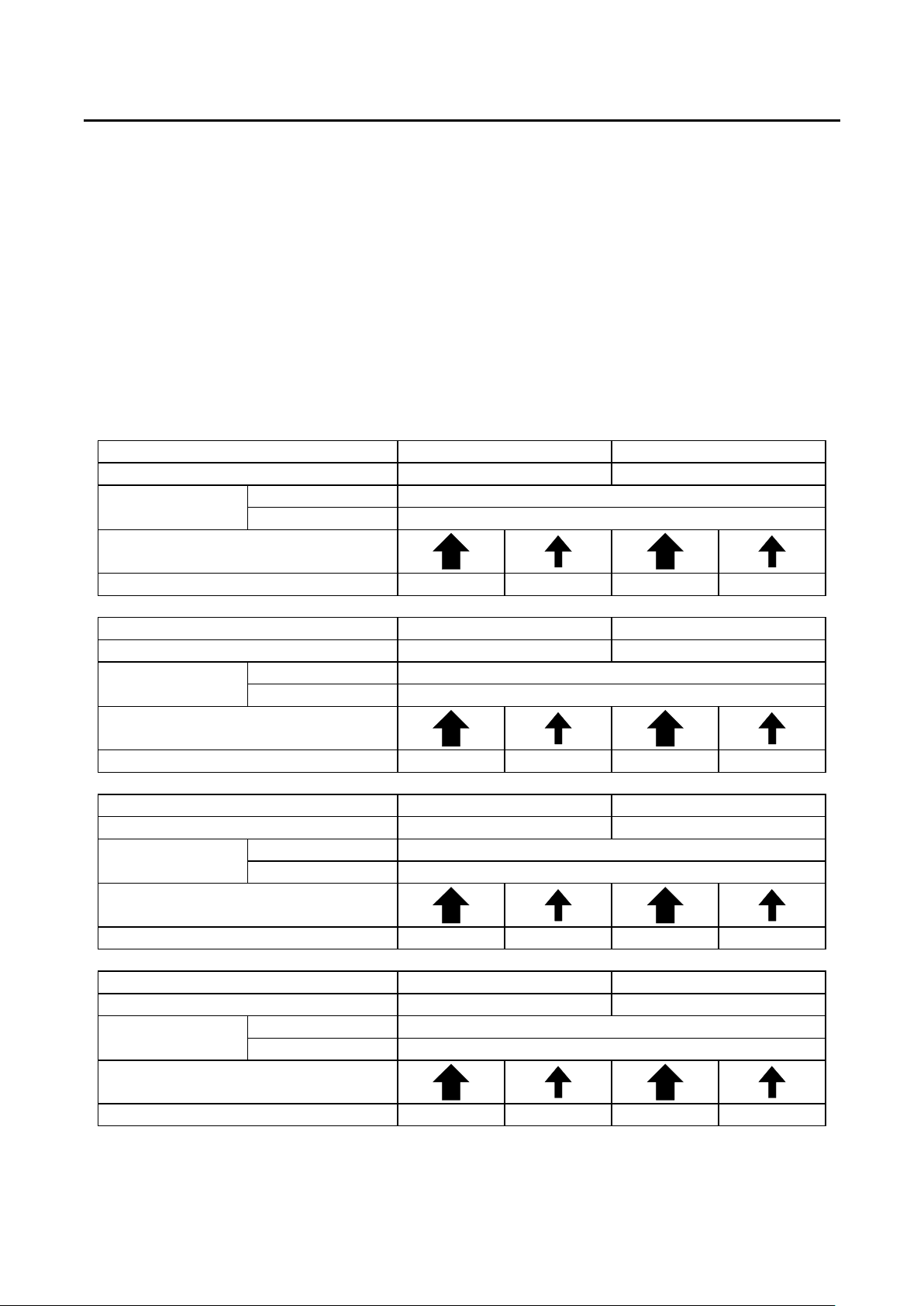
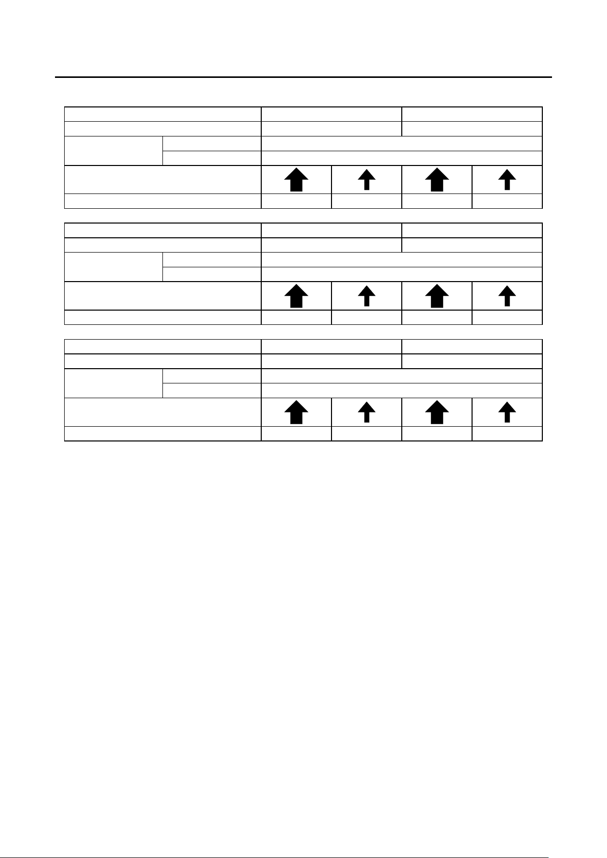
The maximum load current of 3260A Series High Power Electronic Load can be adjusted to
12.000A, 18.000A, 36.000A, 54.000A, 72.000A, 108.000A, 126.00A, and 80.00A respectively.
The relationship between the adjustment variation of the load current or resolution and
buttons is as shown in Table 3-11. During operation, when the time for depressing one of the
four buttons, e.g., rough tuning, fine tuning, increment and decrement, exceeds one second,
the resolution of load current adjustment shall change once per 10ms, e.g., the speed for
variation of load current will increase so that setting the load current can be completed in the
shortest period of time. Unless max. or min. value has been reached or depressing has been
interrupted.
3260A Range I Range II
FULL SCALE LOAD CURRENT 6 A 12 A
CURRENT RANGE 12.000 A
METER RESOLUTION 0.001 A
COURSE/FINE LOAD
CURRENT ADJUSTMENT KEY
KEY’S STEP RESOLUTION 15 mA 1.5 mA 30 mA 3 mA
3261A Range I Range II
FULL SCALE LOAD CURRENT 9 A 18 A
CURRENT RANGE 18.000 A
METER RESOLUTION 0.001 A
COURSE/FINE LOAD
CURRENT ADJUSTMENT KEY
KEY’S STEP RESOLUTION 22.5 mA 2.25 mA 45 mA 4.5 mA
32611A Range I Range II
FULL SCALE LOAD CURRENT 18 A 36 A
CURRENT RANGE 36.000 A
METER RESOLUTION 0.01 A
COURSE/FINE LOAD
CURRENT ADJUSTMENT KEY
KEY’S STEP RESOLUTION 45 mA 4.5 mA 90 mA 9 mA
32612A Range I Range II
FULL SCALE LOAD CURRENT 27 A 54 A
CURRENT RANGE 54.000 A
METER RESOLUTION 0.012 A
COURSE/FINE LOAD
CURRENT ADJUSTMENT KEY
KEY’S STEP RESOLUTION 67.5 mA 6.75 mA 135 mA 13.5 mA
Page 37
PRODIGIT 3260A Series Operation Manual 31
32613A Range I Range II
FULL SCALE LOAD CURRENT 36 A 72 A
CURRENT RANGE 72.000 A
METER RESOLUTION 0.012 A
COURSE/FINE LOAD
CURRENT ADJUSTMENT KEY
KEY’S STEP RESOLUTION 90 mA 9 mA 180 mA 18 mA
32615A Range I Range II
FULL SCALE LOAD CURRENT 54 A 108 A
CURRENT RANGE 108.000 A
METER RESOLUTION 0.012 A
COURSE/FINE LOAD
CURRENT ADJUSTMENT KEY
KEY’S STEP RESOLUTION 135 mA 13.5 mA 270 mA 27 mA
32616A Range I Range II
FULL SCALE LOAD CURRENT 63 A 126 A
CURRENT RANGE 126.00 A
METER RESOLUTION 0.014 A
COURSE/FINE LOAD
CURRENT ADJUSTMENT KEY
KEY’S STEP RESOLUTION 157.5 mA 15.75 mA 315 mA 31.5 mA
Table 3-11 3260A Series Rough Tuning, Fine Tuning & Increment & Decrement Adjustment of Load
Current
Page 38

32 PRODIGIT
3-8 Imonitor (Output)
Imonitor BNC output is designed to monitor the input load current of electronic load. It can be
connected with oscillograph or recorder for observation.
Via the isolated insulation amplifier in the 3260A Series High Power Electronic Load, Imonitor
can output 0~4Vrms/0~10 Vp-p full scale signal to indicate mean root square value (peak
value) load current from 0 to full scale. The isolated insulation voltage between the load input
end of the 3260A electronic load and Imonitor BNC output end is 500V. Also, the reference
potential at the negative end of BNC is the same as the GPIB earth potential of 3260A Series
High Power Electronic Load. As the isolated insulation amplifier inside the 3260A Series High
Power Electronic Load can provide a complete and convenient testing solution, It can not
only solve the problem on voltage and current during testing, But also the problem of earth
phase connection when one oscillograph is used for observation, because in general
oscillograph, the negative end Ch1 of input BNC communicates with Ch2 and has the same
potential as that of the housing of ocillograph.
In observation of the current wave form of the positive and negative output power source of
the power source to be measured, the isolated insulation characteristics are very effective. In
such a way, connection with the oscillograph sharing same input will not create the output
short-circuit on the object to be measured because the reference potential of Imonitor output
in general electronic load can communicate with the negative end of load input, e.g., if there
is no isolated insulation amplifier for the same potential, short-circuit will happen upon
measuring.
Page 39
PRODIGIT 3260A Series Operation Manual 33
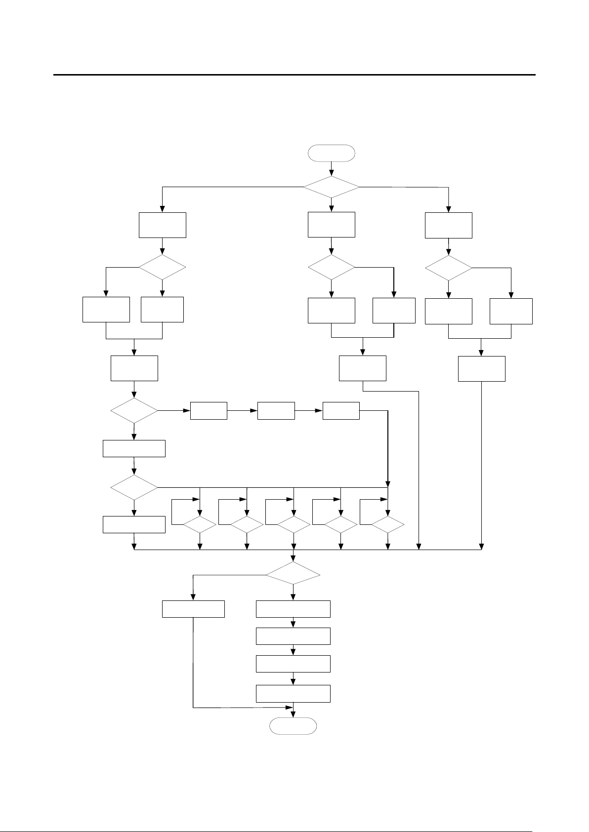
3-9 Operation Flow Chart of 3260A Series Electronic Load
The typical load and procedures for setting the condition of 3260A Series High Power
Electronic Load are shown in Fig.3-4.
STA RT
A
Set
Level A
Set
Current
Freq ?
Last setting Freq
CC mode
Level ?
Level B
YES
NO
Set
Set
CC
B
Pre s
Fre q
Set
Freq
Pre s
Fre q
Set
Bank
Pre s
Freq
M ode ?
CR
Set
CR mode
Level ?
A
Set
Level A
Set
Sync
Set
Resister
Pres
Fre q
B
Set
Level B
LIN
Set
LIN mode
Level ?
A
Set
Level A
B
Set
Level B
Set
Linear C C
W AV E ?
NO
Last wave form
Fig.3-4 3260A Series High Power Electronic Load Operation Flow Chart
YES
NO N O NO N O NO
Linit ?
YES
Last settin g
Set Vm ete r lim it
Set Am ete r lim it
Set Wm eter lim it
Set VA meter lim it
STO P
3.5 ?3.0 ?2 .5 ?√ 2 ? 2 .0 ?
Page 40
34 PRODIGIT
3-10 Protection Features
There are four protection functions for the 3260A Series High Power Electronic Load, namely,
Over-Voltage, Over-Current, Over-Power and Over-Temperature. When electronic load
exceeds the normal work area range, one of the above 4 functions will come to effect. When
any one protection comes to effect, load will be changed to OFF to protect electronic load
thus preventing damage resulting from abnormal operation range. Also, protection status is
indicated by flickering to allow the user understand present condition. Various protection
functions are cited below:
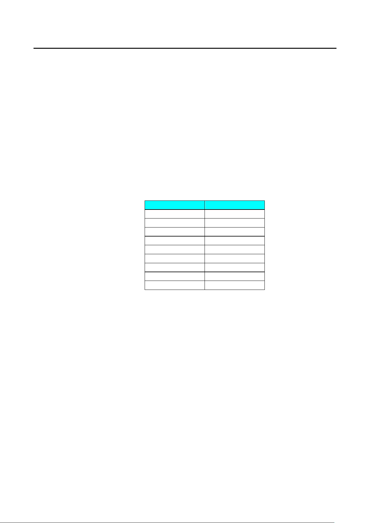
3.10.1 Over Voltage
The protection point of over voltage protection (O.V.P.) is preset in the 3260A series
High Power electronic load. The setting values of over voltage protection are shown
on table 3-12. When O.V.P occurs, the 4 1/2 digit monitor on the upper side of the
front panel of 3260A series High Power electronic load will display〝oVP〞with
flickering to indicate 〝 Under Protection 〞 . Once the over voltage condition
disappears, the upper 4 1/2 digit monitor will resume to normal condition.
Table 3-12 3260A Series over voltage protection setting value
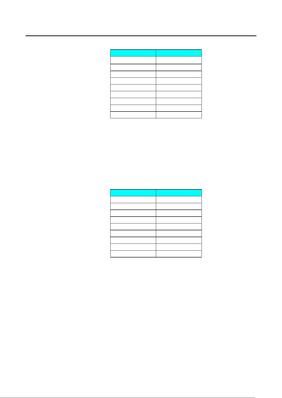
3.10.2 Over Current
The protection point of over current protection (O.C.P.) is preset in the 3260A series
High Power electronic load. The setting values of over current protection are shown
on table 3-13. When O.C.P. occurs, the 4 1/2 digit monitor on the lower side of the
front panel of series High Power electronic load will display〝oCP〞with flickering to
indicate〝Under Protection〞.Once the over current condition disappears, the lower 4
1/2 digit monitor will resume to normal condition.
Model O.V.P.
3260A 315.0 V
32601A 315.0 V
3261A 315.0 V
32611A 315.0 V
32612A 315.0 V
32613A 315.0 V
32614A 315.0 V
32615A 315.0 V
32616A 315.0 V
Page 41
PRODIGIT 3260A Series Operation Manual 35
Model O.C.P.
3260A 12.6 A
32601A 25.2 A
3261A 18.9 A
32611A 37.8 A
32612A 56.7 A
32613A 75.6 A
32614A 94.5 A
32615A 113.4 A
32616A 132.3 A
Table 3-13 3260A Series over current protection setting value
3.10.3 Over Power
The protection point of over power protection (O.P.P.) is preset in the 3260A series
High Power electronic load. The setting values of over power protection are shown
table 3-14. When O.P.P. occurs, the 4 1/2 digit monitor on the lower side of the front
panel of 3260A series High Power electronic load will display〝oPP〞with flickering
to indicate〝Under Protection〞.Once the over power condition disappears, the lower
4 1/2 digit monitor will resume to normal condition.
Model O.P.P.
3260A 1260 VA
32601A 2520 VA
3261A 1890 VA
32611A 3780 VA
32612A 5670 VA
32613A 7560 VA
32614A 9450 VA
32615A 11340 VA
32616A 13230 VA
Table 3-14 3260A Series over power protection setting value
3.10.4 Over Temperature
3260A Series High Power electronic load is provided with temperature sensor. When
the temperature of heat dissipater exceeds about 85 ±5 ,over temperature ℃ ℃
protection will occur and 4 1/2 digit monitor at the lower side of the front panel of
3260A series High Power electronic load will display〝oTP〞with flickering indicates
〝Under Protection〞. Once the over temperature condition disappears, the lower 4
1/2 digit monitor will resume to normal.
Upon occurrence of over temperature protection, please check the ambient working
temperature and ventilation for normality. Please note that the air outlet on the back
of the electronic load shall be away from the wall by more than 15 cm to keep good
ventilation.
Page 42

36 PRODIGIT
3-11 Load ON voltage adjustment
The factory set " Load ON " voltage is 2 volt, the 3260A series Electronic load module starts
to sink current from power supply until the input voltage of 3260A series Electronic Load
module over the "Load ON" voltage.
The adjustable " Load ON " voltage is ranged from 2V to 20V, and is set by VR4 on the PCB
3.11.1 As the load ON voltage setting trimmer is located at the first PCB (P/N: 6523261A01 ).
3.11.2 Remove the 3260A mainframe's right hand side Alumina plate by loosen its screw on
the rear panel.
3.11.3. Using screw drive to set the VR4 to the most counter clockwise position. ( Maximum
load ON voltage ) then connect the AC power source(50Hz or 60Hz) to the AC Load
input of 3260A series module, adjust the AC output voltage to the required Load ON
voltage, the voltage of AC power source should be less than the maximum rating of
the LOAD ON voltage.
3.11.4 Set Load ON/OFF key to ON state, the "load" LED annuciator should be ON on the
front panel, and set the load current to 1 Amp by using Preset key, the set the Preset
OFF again after the load current is set.(Freq.= 50Hz or 60Hz)
3.11.5 Adjust the load ON voltage setting trimmer VR4 clockwise very slowly and stop
immediately until the load start to sink current from power source , then the LOAD
ON voltage setting is finished in this procedure.
3.11.6 Using the reverse procedure to re-install the 3260A series Electronic load module.
Page 43
PRODIGIT 3260A Series Operation Manual 37
Chapter 4 GPIB/RS-232C Operation
4-1 Introduction
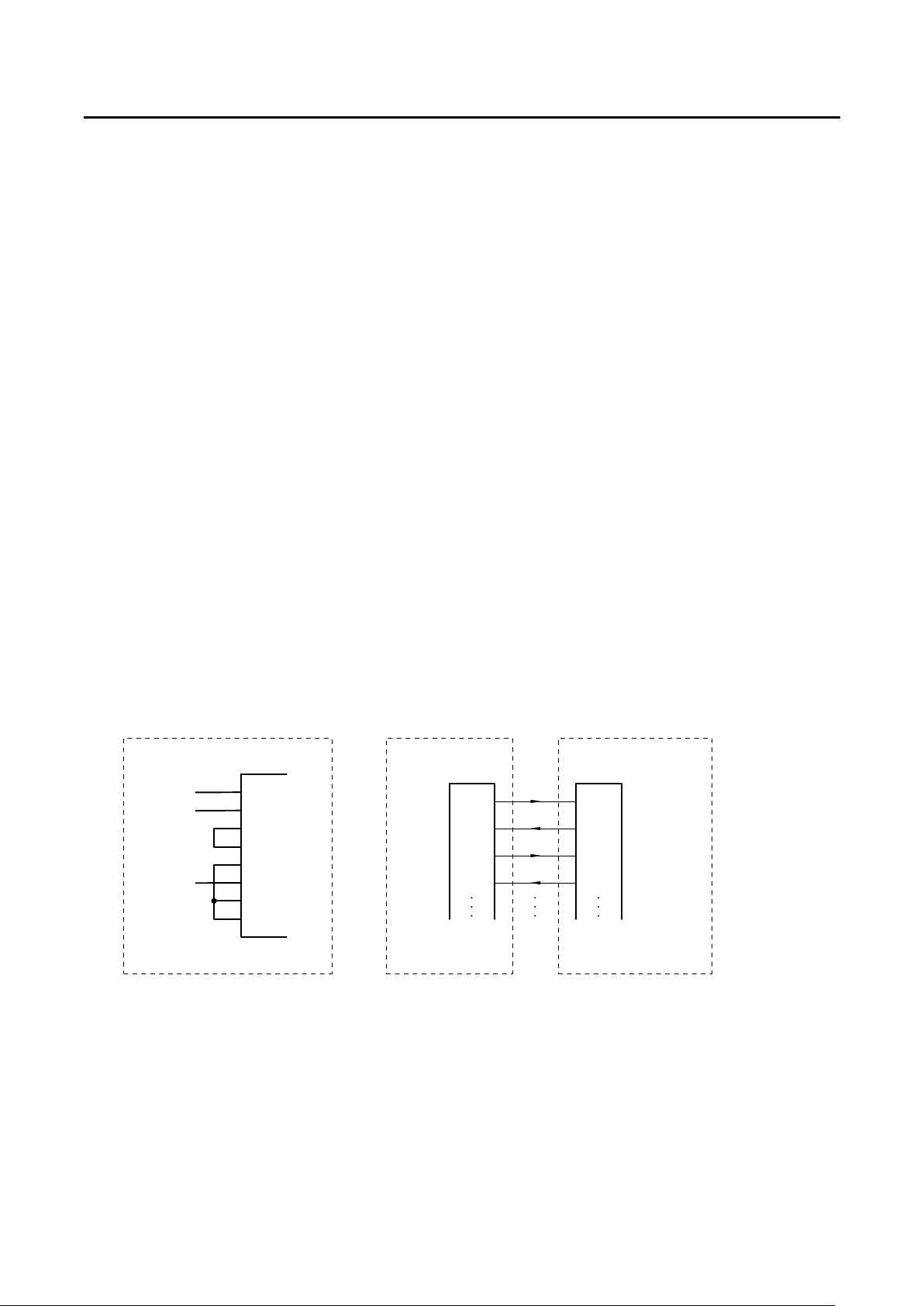
The rear panel GPIB/RS-232C interface of 3260A Series is designed to connect PC
( Personal Computer ) or NOTEBOOK PC with GPIB/RS-232C interface, the NOTEBOOK
PC acts as a remote controller of 3260A series Electronic Load.
This feature can be used as an automatic load/cross load regulation and centering voltage
testing for a switching power supply or an rechargeable battery charge/discharge
characteristic testing. The function capability of rear panel GPIB/RS-232C interface not only
can set the load level and load status, but also can read back the load voltage and load
current.
4-2 The summary of RS-232 interface and command
The following RS-232 commands are same as GPIB commands. The RS-232 protocol in
3302C mainframe is listing below:
Baud-rate :9600
Parity :none
Data bit :8 bits
Stop bit :1 bit
command delay time :20 mSec.
The connection of rear panel RS-232 interface is shown below, The Figure 4-1.a is
connector wire diagram of rear panel RS-232 interface, User can use the general RS-232
cable as Figure 4-1.b.
Inside of 3300C Mainframe
2
TxD
3
RxD
4
RTS
5
CTS
6
DSR
7
GND
8
DCD
9
DTR
RS232C port on
3300C Mainframe
TxD
RxD
RTS
CTS
RS232C port on PC
TxD
RxD
RTS
CTS
Figure 4-1.a
Figure 4-1.b
Fig 4-1 Rs-232 INTERFACE DIAGRAM
Page 44
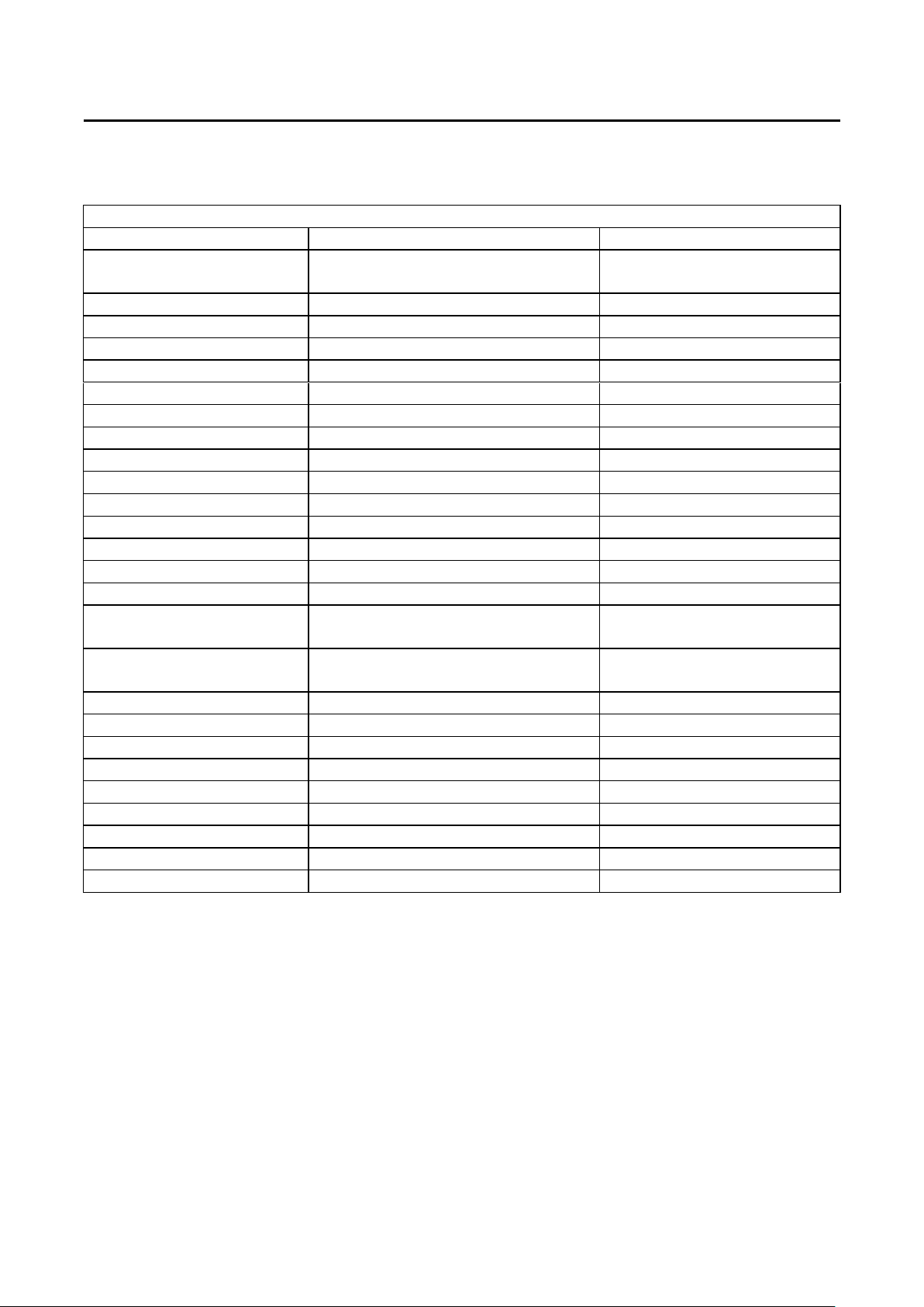
38 PRODIGIT
4-3 3260A Series GPIB/RS-232C COMMAND LIST
Setting Command
Function Command Format
SET AUTO FREQUENCY
DETECT ON/OFF
SET SYNC ON/OFF SYNC{SP}{0|1|OFF|ON}{;|NL}
SET SENC ON/OFF SENS{SP}{0|1|OFF|ON}{;|NL}
SET WATT ON/OFF WATT{SP}{0|1|OFF|ON}{;|NL}
SET BANK BANK{SP}{d}{;|NL} d:0 ~ 10
SET WAVE WAVE{SP}{m}{;|NL}} m:0 ~ 4
SET FREQUENCY FREQ{SP}{NR2}{;|NL} NR2:###.#####
SET VOLTAGE LOW LIMIT VL{SP}{NR2}{;|NL}
SET VOLTAGE HIGH LIMIT VH{SP}{NR2}{;|NL}
SET CURRENT LOW LIMIT IL{SP}{NR2}{;|NL}
SET CURRENT HIGH LIMIT IH{SP}{NR2}{;|NL}
SET WATT LOW LIMIT WL{SP}{NR2}{;|NL}
SET WATT HIGH LIMIT WH{SP}{NR2}{;|NL}
SET VA LOW LIMIT VAL{SP}{NR2}{;|NL}
SET VA HIGH LIMIT VAH{SP}{NR2}{;|NL}
SET CURRENT
SET RESISTANCE
SET LINEAR CURRENT LIN:{A|B}{SP}{NR2}{;|NL}
SET LOAD ON/OFF LOAD{SP}{0|1|OFF|ON}{;|NL}
SET LEVEL LOW/HIGH LEV{SP}{0|1|LOW|HIGH}{;|NL}
SET PRESENT ON/OFF PRES{SP}{0|1|OFF|ON}{;|NL}
SET MODE MODE{SP}{0|1|2|CC|CR|LIN}{;|NL}
SET STORE STATE STORE{SP}{m}{;|NL} m:1 ~ 5
SET RECALL STATE RECALL{SP}{m}{;|NL} m:1 ~ 5
SET REMOTE STATE REMOTE{;|NL} Omly RS232 cmd
SET LOCAL STATE LOCAL{;|NL} Omly RS232 cmd
Table 4-1 GPIB/RS-232C SETTING COMMAND SUMMARY
REMARK :
1. CURRENT ENGINEERING UNIT : A
2. VOLTAGE ENGINEERING UNIT : V
3. RESISTANCE ENGINEERING UNIT : Ω
AFREQ{SP}{0|1|OFF|ON}{;|NL}
CURR:
{LOW|HIGH|A|B}{SP}{NR2}{;|NL}
RES:{LOW|HIGH|A|B}{SP}{NR2}{;
|NL}
NR2:###.#####
Page 45
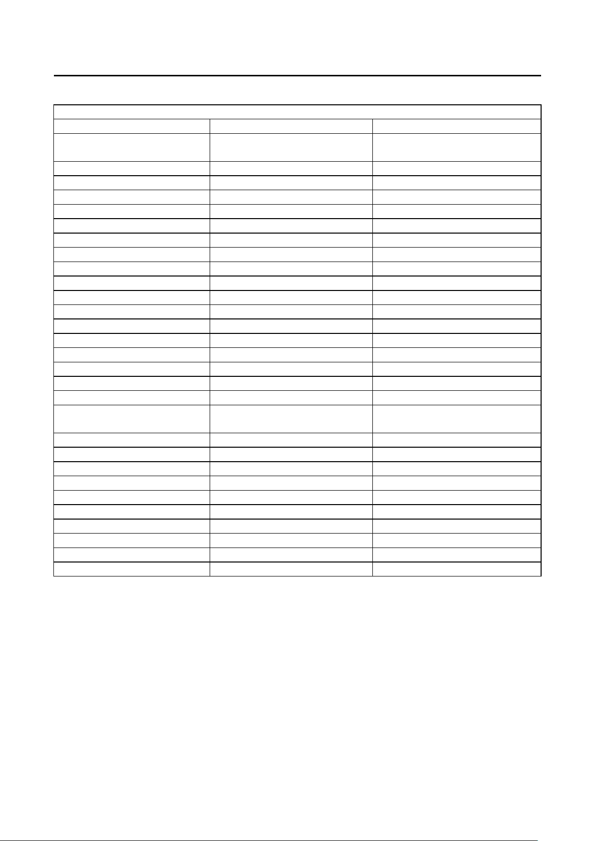
PRODIGIT 3260A Series Operation Manual 39
QUERY AUTO FREQUENCY
Query Command
Function Command Syntax ECHO
AFREQ?{;|NL} 1:ON, 0:OFF
DETECT ON/OFF
QUERY SYNC SYNC?{;|NL} 1:ON, 0:OFF
QUERY SENS ON/OFF SENS?{;|NL} 1:ON, 0:OFF
QUERY WATT ON/OFF WATT?{;|NL} 1:ON, 0:OFF
QUERY BANK BANK?{;|NL} 0 ~ 10
QUERY WAVE WAVE?{;|NL} 0 ~ 4
QUERY FREQUENCY FREQ?{;|NL} ###.####
QUERY VOLTAGE LOW LIMIT VL?{;|NL} ###.####
QUERY VOLTAGE HIGH LIMIT VH?{;|NL} ###.####
QUERY CURRENT LOW LIMIT IL?{;|NL} ###.####
QUERY CURRENT HIGH LIMIT IH?{;|NL} ###.####
QUERY WATT LOW LIMIT WL?{;|NL} ###.####
QUERY WATT HIGH LIMIT WH?{;|NL} ###.####
QUERY VA LOW LIMIT VAL?{;|NL} ###.####
QUERY VA HIGH LIMIT VAH?{;|NL} ###.####
QUER POWER METER (W) MEAS:POW?{;|NL} ###.####
QUERY VA METER MEAS:VA?{;|NL} ###.####
QUERY No Good INDICATER NG?{;|NL} 0:OFF, 1:ON
QUERY CURRENT CURR : {LOW|HIGH|A|B} ? { ;
###.####
|NL}
QUERY RESISTANCE RES:{LOW|HIGH|A|B}?{;|NL} ###.####
QUERY LINEAR CURRENT LIN:{A|B}?{;|NL} ###.####
QUERY LOAD ON/OFF LOAD?{;|NL} 1:ON, 0:OFF
QUERY LEVEL A/B LEV?{;|NL} 0:LOW/A, 1:HIGH/B
QUERY PRESET ON/OFF PRES?{;|NL} 1:ON, 0:OFF
QUERY MODE CC/CR/LIN MODE?{;|NL} 0:CC, 1:CR, 2:LIN
QUERY NAME NAME?{;|NL} 326X SERIES
QUERY PROTECT STATE PROT?{;|NL} 0 ~ F(hex)
QUERY CURRENT METER MEAS:CURR?{;|NL} ±###.####
QUERY VOLTAGE METER MEAS:VOLT?{;|NL} ±##.####
Table 4-2 GPIB/RS-232C QUERY COMMAND SUMMARY
REMARK :
1. CURRENT ENGINEERING UNIT:A
2. VOLTAGE ENGINEERING UNIT:V
3. RESISTANCE ENGINEERING UNIT:Ω
Page 46
40 PRODIGIT
4-4 The description of abbreviation
1. SP:Space, the ASCII code is 20 Hexadecimal.
2. ; :Semicolon, Program line terminator, the ASCII code is OA Hexadecimal.
3. NL:New line, Program line terminator, the ASCII code is OA Hexadecimal.
4. N :Integer number from 1 to 8.
5. NR2:Digits with decimal point. It can be accepted in the range and format of ##.#####.
For Eexample:
10.12345, 5.0
The description of GPIB/RS-232C programming command syntax.
1. { }:The contents of the { } symbol must be used as a part or data of the GPIB/RS-232C
command, it can not be omitted.
2. [ ]:The contents of the [ ] symbol indicts the command can be used or not. It depends
on the testing application.
3. | :This symbol means option. For example〝A|B〞means it can only use A or B as the
command, it can choose only one as the setting command.
4. Terminator:You have to send the program line terminator character after send the
GPIB/RS-232C command, the available command terminator characters which can be
accepted in 3260A Series High Power Load is listed in Table 4-3.
Table 4-3 GPIB/RS-232C command terminator
A terminator informs GPIB/RS-232C that it has reached the end of statement. Normally,
this is sent automatically by your GPIB/RS-232C programming statements. In this
manual, the terminator is assumed at the end of each example line of code. If it needs to
be indicated, it is shown by symbol (nl); which stand for〝new line〞and represents
ASCII code byte the OA Hexadecimal or 10 decimal.
5. Semicolon〝;〞:The semicolon〝;〞is a back-up command, the semicolon allows
you to combine command statement on one line to create command message.
LF
LF WITH EOI
CR, LF
CR, LF WITH EOI
Page 47

PRODIGIT 3260A Series Operation Manual 41
4-5 GPIB/RS-232C command description
4.5.1 Setting Command
CURR
Purpose:::: The load current setting in Constant Current mode.
Command syntax::::CURR:{LOW|HIGH|A|B}{SP}{NR2}{NL}
Description::::
This command is used to set the load current LEVEL A/B of 3260A series Electronic
Load.
Note:
1. The load current data must include decimal point, otherwise this command is
2. The HIGH load level load current MUST be higher than LOW level load current for
3. If the programming loads current level over the maximum specification at
4. Engineering unit for load current is Amps.
For Example::::
CURR:A 1.8 ; Set level A load current to 1.8 A.
CURR:B 15.123456 ; Set level B load current to 15.123456 A.
RES
Purpose:::: The load resistance setting in Constant Resistance mode.
Command syntax::::RES:{LOW|HIGH|A|B}{SP}{NR2}{NL}
Description:
This command is used to set the load resistance for LEVEL A/B of 3260A series
electronic load.
Note:
1. The load resistance data must include decimal point, otherwise this command is
2. If the programming loads resistance level over the maximum specification at
3. The engineering unit for load resistance is Ohms.
For Example::::
RES:A 9.123 ; Set level A load resistance to 9.123 OHM.
RES:B 13.456789 ; Set level B load resistance to 13.456789 OHM.
unable to execute. The effective load current level can be programmed is the sixth
digit after the decimal point.
proper dynamic waveform definition, the load current difference between
programmed HIGH and LOW level is 10 times of resolution at each range, the
3260A series Electronic Load will adjust and limit of the programmed values.
programmed range of 3260A series load, the full scale current will be sent to the
load module.
unable to execute. The most effective load resistance level can be set is the sixth
digit after the decimal point.
programmed range of 3260A series load, the full scale resistance will be sent to
the load module.
Page 48

42 PRODIGIT
LIN
Purpose:::: The load linear current setting in Constant Current mode.
Command syntax::::LIN:{LOW|HIGH|A|B}{SP}{NR2}{NL}
Description::::
This command is used to set the load current LEVEL A/B of 3260A series Electronic
Load.
Note:
1. The load current data must include decimal point, otherwise this command is
unable to execute. The effective load current level can be programmed is the sixth
digit after the decimal point.
2. The HIGH load level load current MUST be higher than LOW level load current for
proper dynamic waveform definition, the load current difference between
programmed HIGH and LOW level is 10 times of resolution at each range, the
3260A series Electronic Load will adjust and limit of the programmed values.
3. If the programming loads current level over the maximum specification at
programmed range of 3260A series load, the full scale current will be sent to the
load module.
4. Engineering unit for load current is Amps.
For Example::::
LIN:A 1.8 ; Set level A load linear current to 1.8 A.
LIN:B 15.123456 ; Set level B load linear current to 15.123456 A.
LOAD
Purpose::::
Turn the Electronic load module input ON or OFF.
Command syntax:LOAD{SP}{0FF|ON}{NL}
Description::::
This command sets the Electronic load to sink current from AC/DC power source.
LOAD ON the 3260A series Electronic load are ready to sink current from AC/DC
power source.
For Example::::
LOAD 0 ; Set the load "LOAD OFF".
LEV
Purpose::::
Select LEVEL A or B of 3260A series electronic load.
Command syntax:LEV{SP}{0|1|A|B}{NL}
Description::::
LEV A The condition and setting of electronic load adopt the set value of LEVEL A.
LEV B The condition and setting of electronic load adopt the set value of LEVEL B.
Page 49

PRODIGIT 3260A Series Operation Manual 43
PRES
Purpose::::
Set the upper or lower 4 1/2 digit multi-function meter to display the programming
load level.
Command syntax::::PRES{SP}{0|1|OFF|ON}{NL}
Description::::
PRES ON set the load to preset on status.
MODE
Purpose::::
Select the operating mode of Electronic load module.
Command syntax::::MODE{SP}{0|1|2|CC|CR|LIN}{NL}
Description::::
MODE CC set the presently operating mode to Constant Current mode for 3260A
Series Load.
MODE CR set the presently operating mode to Constant Resistance mode.
MODE 1 set the presently operating mode to Constant Resistance mode.
STORE
Purpose::::
STORE the load level and load status into the non-volatile memory of the 3260A
series electronic LOAD.
Command syntax::::STORE{SP}{1|2|3|4|5}{NL}
Description::::
5 different states with 3260A series electronic load's status and load current into the
non-volatile memory in the 3260A series electronic load.
Note:
The new load level and load status can overcome the load level and status if
STORE new state number, because the memory location is the same for same
STORE state number.
For Example::::
STORE 1
STORE 5
Page 50

44 PRODIGIT
RECALL
Purpose::::
Recall the state of load level and status which is stored by GPIB STORE command.
Command syntax::::RECALL{SP}{1|2|3|4|5}{NL}
Description::::
This command is used to recall the non-volatile memory state which is store into the
memory by GPIB store command, up to 5 states can be recalled.
For Example::::
RECALL 1
RECALL 4
SYNC
Purpose::::
To set synchronous function.
Command syntax::::SYNC{SP}{0|1|OFF|ON}{;|NL}
Description:
1. External synchronous signal (SYNC ON):Using external synchronous signal as
2. Internal synchronous signal (SYNC OFF):Using the signal at the terminal of the
For Example::::
a. SYNC ON ; To set external synchronization.
b. SYNC OFF ; To set internal synchronization.
the Asynchronous triggering signal of the electronic load thus controlling the load
current to be synchronous with the voltage.
input connector thus generating synchronous signal through the internal zerocrossing circuit and isolated circuit.
WATT
Purpose::::
To set display of power meter.
Command syntax::::WATT{SP}{0|1|OFF|ON}{;|NL}
Description::::
This command is to set the display of power meter. This command has to be used in
conjunction with PRES:OFF. When setting to ON, the monitor on the top will
change from voltmeter to Watt meter while the monitor at the bottom will change from
ammeter to Volt-Ameter (VA) and the unit is〝W〞and〝VA〞respectively. When
setting to OFF, the Watt meter on the top will change back to voltmeter while the VA
meter at the bottom will change back to ammeter and the unit is〝Vrms〞and
〝Arms〞respectively.
For Example::::
a. PRES OFF
b. WATT ON ; To display WATT, VA meter.
c. WATT OFF ; To display Voltage, Current meter.
Page 51
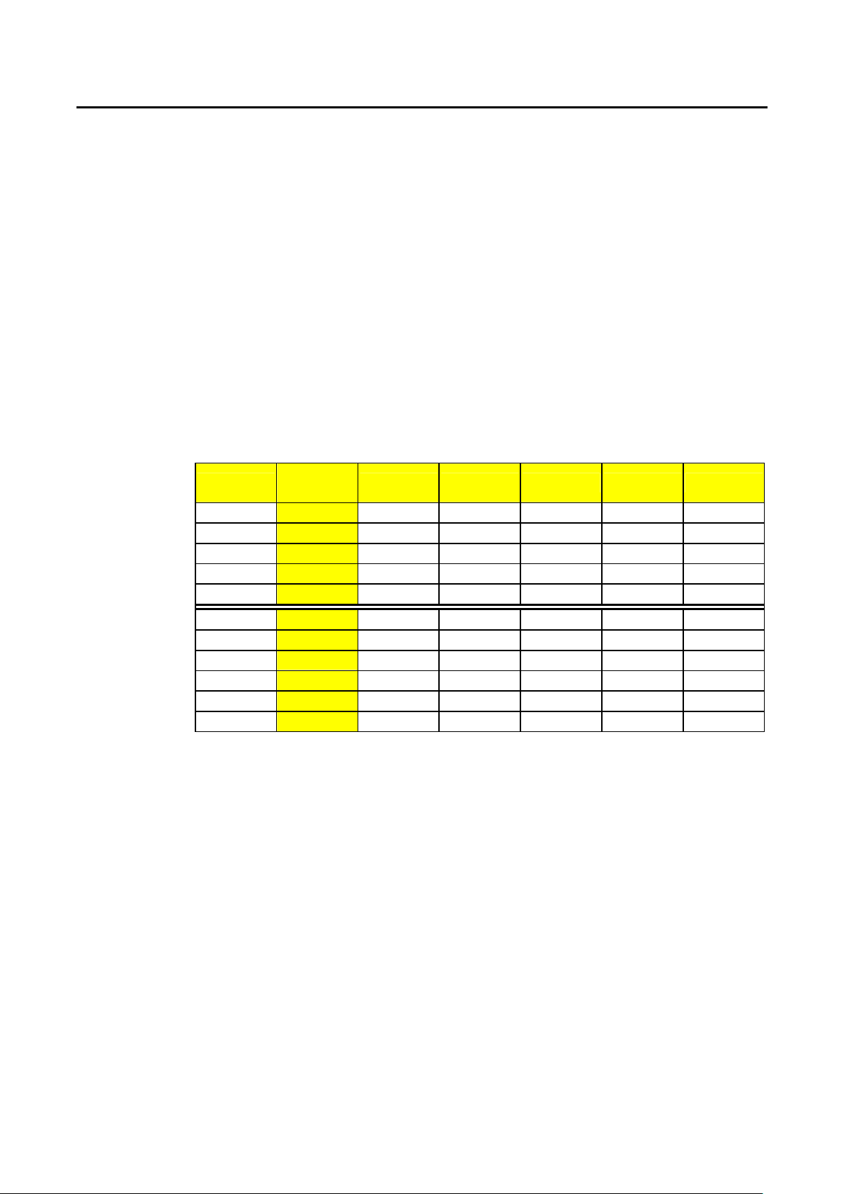
PRODIGIT 3260A Series Operation Manual 45
BANK
Purpose::::
To set waveform bank.
Command syntax::::BANK{SP}{d}{;|NL} d:0~10
Description::::
This command is to set the waveform bank desired to be selected.
1. waveform bank 0~2 are sine wave.
2. waveform bank 3~8 are P.F..
3. waveform bank 9 are square wave.
4. waveform bank 10 is DC.
5. There are five (5) waveform information for each waveform bank, therefore, there
is a total 55 waveform information for eleven (11) waveform banks. Waveform
information is shown in Table 4-4.
For Example::::
a. BANK 1 ; To set waveform bank 1.
b. BANK 10 ; To set waveform bank 10.
sine wave
Wave
From Bank
A B C D E
0 √2 2.0 2.5 3.0 3.5
1 1.5 1.6 1.7 1.8 1.9
2 3.0 3.1 3.2 3.3 3.4
C.F.= 2.0
C.F.= 2.5
3 P.F.=-0.85 P.F.=-0.80 P.F.=-0.75 P.F.=-0.70 P.F.=-0.65
4 P.F.=-0.70 P.F.=-0.65 P.F.=-0.60 P.F.=-0.50 P.F.=-0.40
C.F.= 3.5
C.F.= 2.0
C.F.= 2.5
C.F.= 3.5
square wave
5 P.F.=-0.50 P.F.=-0.45 P.F.=-0.40 P.F.=-0.35 P.F.=-0.30
6 P.F.= 0.85 P.F.= 0.80 P.F.= 0.75 P.F.= 0.70 P.F.= 0.65
7 P.F.= 0.70 P.F.= 0.65 P.F.= 0.60 P.F.= 0.50 P.F.= 0.40
8 P.F.= 0.50 P.F.= 0.45 P.F.= 0.40 P.F.= 0.35 P.F.= 0.30
9 1.0 1.1 1.2 1.3 1.4
DC 10 √2dc 2dc 2.5dc 3.0dc 3.5dc
Table 4-4 waveform information
WAVE
Purpose::::
To set waveform.
Command syntax::::WAVE{SP}{m}{;|NL}m:0~4
Description::::
This command is to set the current C.F. at CC MODE (Peak Value Factor).
This command works only at CC MODE. When BANK varies, these 5 sets of C.F. will
at the same time define different C.F. as shown in Table 4-4. For details, please refer
to 3260A Operation Manual.
For Example::::
a.WAVE 1 ; To set 2nd set C.F.
b.WAVE 4 ; To set 5th set C.F.
Page 52

46 PRODIGIT
FREQ
Purpose::::
Setting of Frequency Value.
Command syntax::::FREQ{SP}{NR2}{;|NL}
Description::::
This command is for setting the frequency value of electronic load. Upon directing
command, attention has to be paid to the following items:
1. The frequency value designated must include the decimals, otherwise, the
2. The minimum effective digit of the value is the fifth digit after the decimal point.
3. If the value designated exceeds the specification of said electronic load, the
4. The frequency range of 3260A series electronic load is DC , 0.1~400.0 Hz.
5. unit is Hz.
For Example::::
a. FREQ 50.0 ; To set frequency is 50.0Hz.
b. FREQ 60.0 ; To set frequency is 60.0Hz.
c. FREQ 0 ; To set frequency is 0Hz, that is to set DC.
VL
Purpose::::
To set the lower limit value of threshold voltage.
Command syntax::::VL{SP}{NR2}{;|NL}
Description::::
This command is to set the lower limit value of threshold voltage. When input voltage
is lower than the lower limit value, NG indicating light will come on to indicate〝NO
GOOD〞.
For Example::::
VL 1.0 ; To set the lower limit value of threshold voltage is 1.0 V.
VH
Purpose::::
To set the upper limit value of threshold voltage.
Command syntax::::VH{SP}{NR2}{;|NL
Description::::
This command is to set the upper limit value of threshold voltage. When input voltage
is higher than the upper limit value, NG indicating light will come on to indicate〝NO
GOOD〞.
For Example::::
VH 200.0 ; To set the upper limit value of threshold voltage is 200.0 V.
command will become null and void.
3260A Series High Power Load will send out the full scale current value of said
electronic load specification.
}
Page 53

PRODIGIT 3260A Series Operation Manual 47
IL
Purpose::::
To set the lower limit value of threshold current.
Command syntax::::IL{SP}{NR2}{;|NL]
Description::::
This command is to set the lower limit value of threshold current. When load sink
current is lower than this lower limit value, NG indicating light will come on to indicate
〝NO GOOD〞.
For Example::::
IL 0.05 ; To set the lower limit value of threshold current.
IH
Purpose::::
To set the upper limit value of threshold current.
Command syntax::::IH{SP}{NR2}{;|NL}
Description::::
This command is to set the upper limit value of threshold current. When load sink
current is high than this upper limit value, NG indicating light will come on to indicate
〝NO GOOD〞.
For Example::::
IH 10.0 ; To set the upper limit value of threshold current is 10.0 A.
WL
Purpose::::
To set the lower limit value of threshold power (W).
Command syntax::::WL{SP}{NR2}{;|NL}
Description::::
This command is to set the lower limit value of threshold power (WATT). When power
(WATT) is lower than this lower limit value, NG indicating light will come on to
indicate〝NO GOOD〞.
For Example::::
WL 0.05 ; To set the lower limit value of threshold power (W) is 0.05 W.
WH
Purpose::::
To set the upper limit value of threshold power (W).
Command syntax::::WH{SP}{NR2}{;|NL}
Description::::
This command is to set the upper limit value of threshold power (WATT). When
power (WATT) is high than this upper limit value, NG indicating light will come on to
indicate〝NO GOOD〞.
For Example::::
WH 250.0 ; To set the upper limit value of threshold power (W) is 250.0 W.
Page 54

48 PRODIGIT
VAL
Purpose::::
To set the lower limit value of threshold power (VA).
Command syntax::::VAL{SP}{NR2}{;|NL}
Description::::
This command is to set the lower limit value of threshold power (VA). When power
(VA) is lower than this lower limit value, NG indicating light will come on to indicate
〝NO GOOD〞.
For Example::::
VAL 0.05 ; To set the lower limit value of threshold power (VA) is 0.05 VA.
VAH
Purpose::::
To set the upper limit value of threshold power (VA).
Command syntax::::VAH{SP}{NR2}{;|NL}
Description::::
This command is to set the upper limit value of threshold power (VA). When power
(VA) is higher than this upper limit value of threshold power (VA), NG indicating light
will come on to indicate〝NO GOOD〞.
For Example::::
VAH 250.0 ; To set the upper limit value of threshold power (VA) is 250.0 VA.
AFREQ
Purpose::::
To set auto frequency detect function.
Command syntax::::AFREQ{SP}{0|1|OFF|ON}{;|NL}
Description:
1.Enable auto frequency detect function (AFREQ ON):3260A series electronic load
will auto frequency external signal to control load current and voltage synchronous.
At this time if place “FREQ” command, it will be ineffective.
2.Disable auto frequency detect function (AFREQ OFF):at this time user needs to
make frequency setting. When AFREQ OFF, the frequency will be fixed on the last
detective frequency.
For Example::::
a.AFREQ ON
b.AFREQ OFF
REMOTE
Purpose::::
Go to remote.
Command syntax::::REMOTE{;|NL}
Description::::
Let control procedure enter into remote state.
Page 55

PRODIGIT 3260A Series Operation Manual 49
LOCAL
Purpose::::
Return to local.
Command syntax::::LOCAL{;|NL}
Description::::
Let control procedure return to the mode of local operation.
Page 56

50 PRODIGIT
4.5.2 Query Command
CURR
Purpose::::
The Constant Current mode's level A or B load current setting query command.
Command syntax::::CURR:{A|B}?{NL}
Description::::
CURR:A? ; Return the LEVEL A load current setting of 3260A series electronic load.
CURR:B? ; Return the LEVEL B load current setting of 3260A series electronic load.
The returned data format is shown in Table 4-2, the engineering unit is〝A〞.
RES
Purpose::::
The Constant Resistance mode's level A or B load resistance setting query command.
Command syntax::::RES:{A|B}?{NL}
Description::::
RES:A? ; Return the LEVEL A load resistance setting of 3260A series electronic load.
RES:B? ; Return the LEVEL B load resistance setting of 3260A series electronic load.
The returned data format is shown in Table 4-2, the engineering unit is〝OHM〞.
LIN
Purpose::::
The Linear Current mode's level A or B load current setting query command.
Command syntax::::LIN:{A|B}?{NL}
Description::::
LIN:A? ; Return the LEVEL A load linear current setting of 3260A series electronic
load.
LIN:B? ; Return the LEVEL B load linear current setting of 3260A series electronic
load.
The returned data format is shown in Table 4-2, the engineering unit is〝A〞.
LOAD
Purpose::::
LOAD ON or LOAD OFF status query command.
Command syntax::::LOAD?{NL}
Description::::
LOAD? ; Return the presently load status,〝0〞indicates LOAD OFF, and〝1〞
indicates LOAD ON.
LEV
Purpose::::
Active LEVEL of 3260A series electronic load query command..
Command syntax::::LEV?{NL}
Description::::
LEV? ; Return the presently level status,〝0〞indicates LEVel A, and〝1〞indicates
LEVel B.
Page 57
PRODIGIT 3260A Series Operation Manual 51
PRES
Purpose::::
PRESet ON or OFF status query command.
Command syntax::::PRES?{NL}
Description::::
PRES? ; Return the presently preset status,〝0〞indicates PRESet OFF, and〝1〞
indicates PRESet ON.
MODE
Purpose::::
CC, LIN or CR operating mode query command.
Command syntax::::MODE?{NL}
Description::::
MODE? ; Return the presently operating mode status,〝0〞indicates CC MODE,
〝1〞indicates CR MODE,〝2〞indicates LIN MODE.
NAME
Purpose::::
3260A series Electronic Load model number query command.
Command syntax::::NAME?{NL}
Description::::
NAME? return the activate Electronic Load’s model number, ”3260A”,
“3261”, ”32611”, “32612” , ”32613” and ”32615” indicate the activate Electronic Load
module is 3260A, 3261A, 32611A, 32612A, 32613A or 32615A Electronic load
respectively.
PROT
Purpose::::
OPP, OTP, OVP, and OCP protection status query command.
Command syntax::::PROT?{NL}
Description::::
PROT? ; Return the presently protection status, the status byte register summarizes
all of the protection status events from all status register. Table 4-5 describes the
status byte the happened on the 3254 series Electronic load. The PROT status byte
register is cleared when a CLER command clear all of the PROT and ERR status
registers.
bit 7 bit 0
7 6 5
Table 4-5 PROT status byte register
4 3
2 1 0
OPP
OTP
OVP
OCP
Page 58

52 PRODIGIT
MEAS::::VLOT
Purpose::::
The reading of 4 1/2 digit voltage meter read back query command.
Command syntax::::MEAS:VOLT?{NL}
Description::::
MEAS:VOLT? ; Return the presently 4 1/2 digital voltage meter reading. The returned
data format is shown in Table 4-2, the engineering unit is〝V〞.
MEAS::::CURR
Purpose::::
The reading of 4 1/2 digit current meter read back query command.
Command syntax::::MEAS:CURR?{NL}
Description::::
MEAS:CURR? ; Return the presently 4 1/2 digital current meter reading. The
returned data format is shown in Table 4-2, the engineering unit is〝A〞.
SYNC
Purpose::::
To read the setting condition of SYNC.
Command syntax::::SYNC?{;|NL}
Description::::
SYNC? ; Read back the condition of SYNC.〝0〞denotes OFF,〝1〞denotes ON.
SENS
Purpose::::
To read the setting condition of Sense ON or OFF.
Command syntax::::SENS?{;|NL}
Description::::
SENS? ; Read back the setting condition of SENS.〝0〞denotes OFF,〝1〞denotes
ON.
WATT
Purpose::::
To read the setting condition of WATT.
Command syntax::::WATT?{;|NL}
Description::::
WATT? ; Read back the setting condition of WATT.〝0〞denotes OFF,〝1〞denotes
ON.
Page 59

PRODIGIT 3260A Series Operation Manual 53
BANK
Purpose::::
To read the set value of BANK
Command syntax::::BANK?{;|NL}
Description::::
BANK? ; Read back the set value of BANK. 0~10 denotes waveform bank of level 0
~level 10.It’s only use C.C. mode.
WAVE
Purpose::::
To read the set value of WAVE.
Command syntax::::WAVE?{;|NL}
Description::::
WAVE? Read back the set value of WAVE. 0~4 denotes the C.F. setting of level 1~
level 5. It’s only use C.C. mode.
FREQ
Purpose::::
To read the set frequency of FREQ.
Command syntax::::FREQ?{;|NL}
Description::::
FREQ? ; Read back the set frequency of FREQ, unit is Hz.
VL
Purpose::::
To read the set value of VL.
Command syntax::::VL?{;|NL}
Description::::
VL? ; Read back the lower limit set value of threshold voltage, unit is (V).
VH
Purpose::::
To read the set value of VH
Command syntax::::VH?{;|NL}
Description::::
VH? ; Read back the upper limit set value of threshold voltage, unit is (V).
IL
Purpose::::
To read the set value of IL.
Command syntax::::IL?{;|NL}
Description::::
IL? ; Read back the lower limit set value of threshold current, unit is (A).
Page 60

54 PRODIGIT
IH
Purpose::::
To read the set value of IH.
Command syntax::::IH?{;|NL}
Description::::
IH? ; Read back the upper limit set value of threshold current, unit is (A).
WL
Purpose::::
To read the set value of WL.
Command syntax::::WL?{;|NL}
Description::::
WL? ; Read back the lower limit set value of threshold power, unit is (W).
WH
Purpose::::
To read the set value of WH.
Command syntax::::WH?{;|NL}
Description:
WH? ; Read back the upper limit set value of threshold power, unit is (W).
VAL
Purpose::::
To read the set value of VAL.
Command syntax::::VAL? {;|NL}
Description::::
VAL? ; Read back the lower limit set value of threshold power, unit is (VA).
VAH
Purpose::::
To read the set value of VAH.
Command syntax::::VAH?{;|NL}
Description::::
VAH? ; Read back the upper limit set value of threshold power, unit is (VA).
NG
Purpose::::
To read the set value of NG.
Command syntax::::NG?{;|NL}
Description::::
NG? ; Read back the condition indicating light of NG.〝0〞denotes that NG (NO
GOOD) indicating light has been extinguished.〝1〞denotes that NG indicating light
has been lit.
Page 61

PRODIGIT 3260A Series Operation Manual 55
MEAS::::POW
Purpose::::
To read the value of Watt meter.
Command syntax::::MEAS:POW?{;|NL}
Description::::
MEAS:POW? ; Read back the value of 4 digit of the Watt meter, unit is (W).
MEAS::::VA
Purpose::::
To read the value of VAmeter.
Command syntax::::MEAS:VA?{;|NL}
Description::::
MEAS:VA? ; Read back the value of 4 digit of VAmeter, unit is (VA).
AFREQ
Purpose:
To read the setting condition of AFREQ.
Command syntax:AFREQ?{;|NL}
Description:
AFREQ?Read back the condition of AFREQ.〝0〞denotes OFF,〝1〞denotes ON.
Page 62
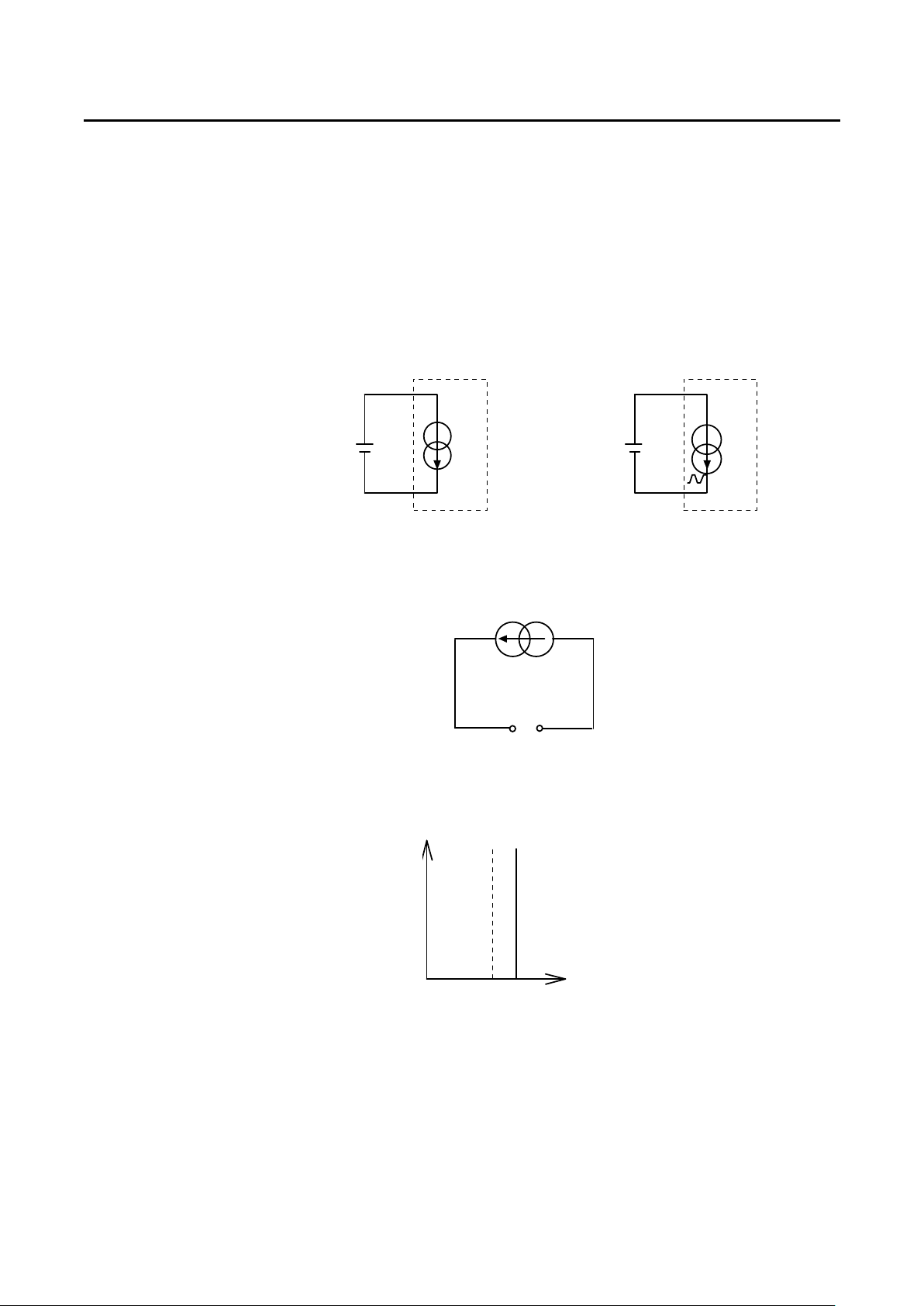
56 PRODIGIT
Chapter 5 Application
Some general application examples for 3260A series High Power electronic load are given in this
chapter.
5-1 CC Operation Mode Application
CC Operation mode is very suitable for load regulation, cross regulation and output voltage
adjust tests of the power supplier and for battery discharge testing and service life cycle
testing.
5.1.1 Voltage Source Testing
VOLTAGE
VOLTAGE
VOLTAGEVOLTAGE
SOURCE
SOURCE
SOURCESOURCE
ELECTRONIC LOAD
ELECTRONIC LOAD
ELECTRONIC LOAD ELECTRONIC LOAD
CC MODE
CC MODE
CC MODECC MODE
5.1.2 Power Supply Load Regulation Testing
VOLTAGE
VOLTAGE
VOLTAGEVOLTAGE
SOURCE
SOURCE
SOURCESOURCE
ELECTRONIC LOAD
ELECTRONIC LOAD
ELECTRONIC LOAD ELECTRONIC LOAD
CC MODE
CC MODE
CC MODECC MODE
5.1.3 Battery Discharge Testing
VVVV
LOAD CURRENT
LOAD CURRENT
LOAD CURRENTLOAD CURRENT
---- +
DC
DC
DCDC
INPUT
INPUT
INPUTINPUT
LOAD CURRENT
LOAD CURRENT
LOAD CURRENTLOAD CURRENT
SETTING
SETTING
SETTINGSETTING
IIII
Page 63
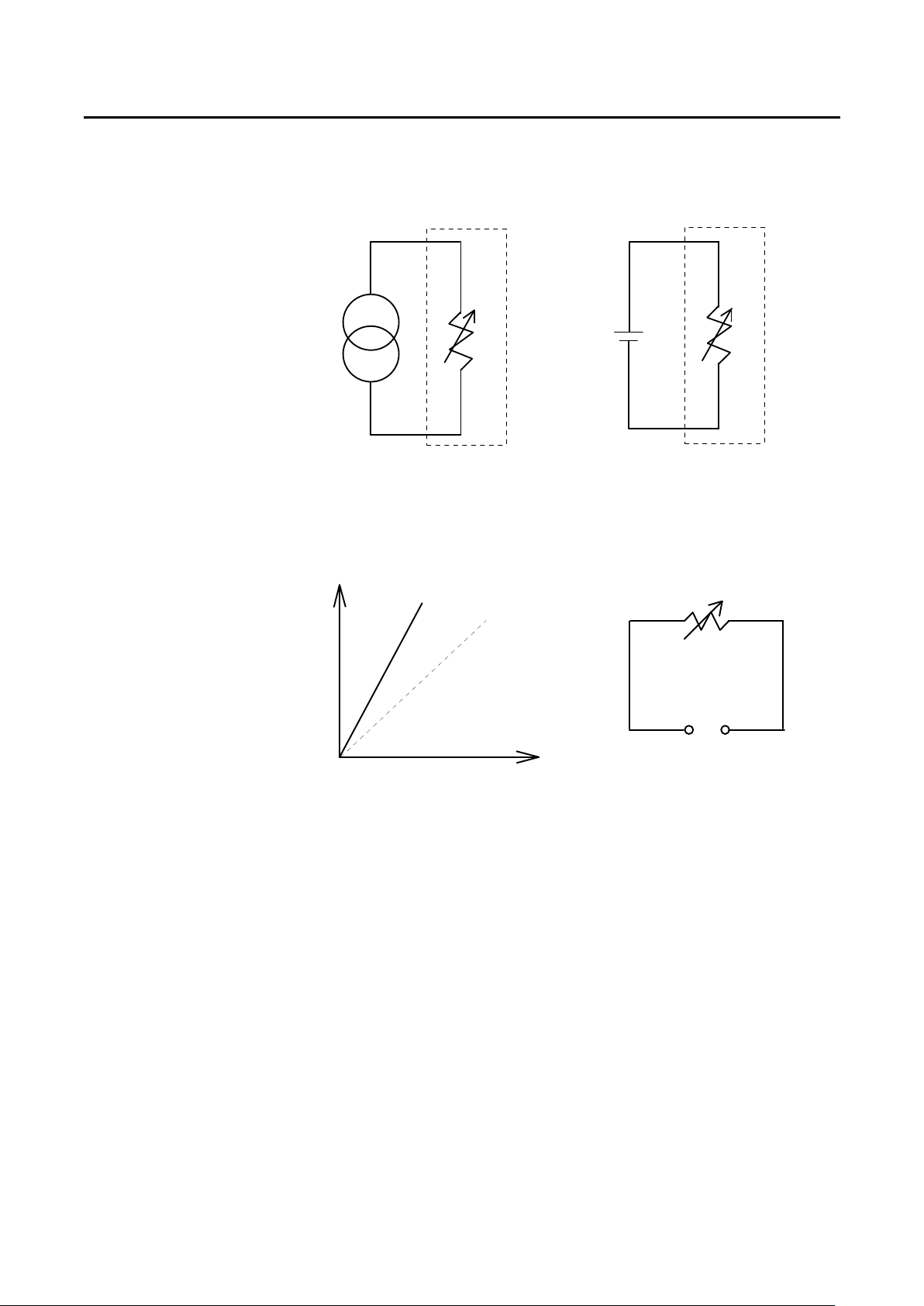
PRODIGIT 3260A Series Operation Manual 57
5-2 CR Operation Mode Application
5.2.1 Voltage Source or Current Source Testing
++++
CURRENT
CURRENT
CURRENTCURRENT
SOURCE
SOURCE
SOURCESOURCE
----
ELECTRONIC
ELECTRONIC LOLAD
ELECTRONICELECTRONIC
CR MODE
CR MODE
CR MODECR MODE
5.2.2 Power Resister Simulation
VVVV
LOLAD
LOLADLOLAD
VOLTAGE
VOLTAGE
VOLTAGEVOLTAGE
SOURCE
SOURCE
SOURCESOURCE
ELECTRONIC
ELECTRONIC LOLAD
ELECTRONICELECTRONIC
CR MODE
CR MODE
CR MODECR MODE
LOLAD
LOLADLOLAD
INPUT
INPUT
INPUTINPUT
VOLTAGE
VOLTAGE
VOLTAGEVOLTAGE
LOAD RESISTANCE
LOAD RESISTANCE
LOAD RESISTANCELOAD RESISTANCE
SETTING
SETTING
SETTINGSETTING
LOAD CURRENT
LOAD CURRENT
LOAD CURRENTLOAD CURRENT
IIII
----
AC
AC
ACAC
OUTPUT
OUTPUT
OUTPUTOUTPUT
++++
Page 64
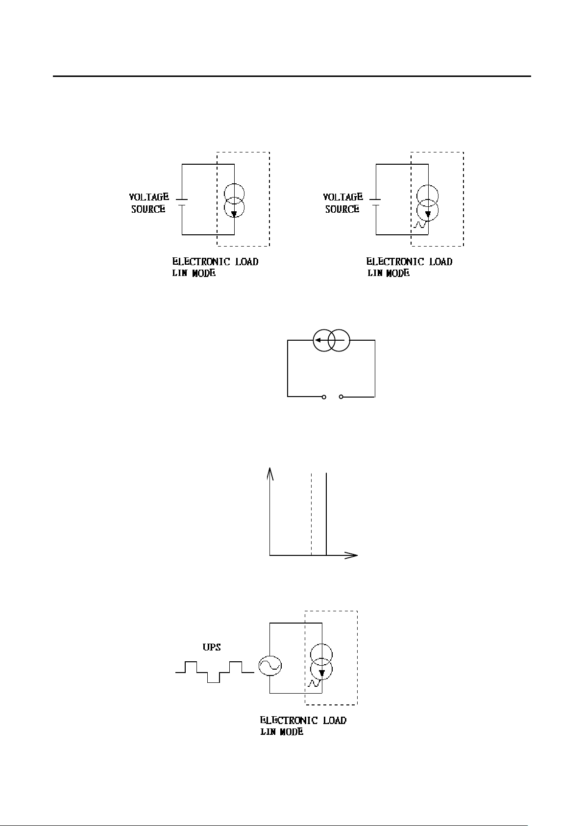
58 PRODIGIT
5-3 LIN Operation Mode Application
5.3.1 Voltage Source Testing
5.3.2 Power Supply Load Regulation Testing
5.3.3 Battery Discharge Testing
5.3.4 Uninterruptible Power Supply
VVVV
LOAD CURRENT
LOAD CURRENT
LOAD CURRENTLOAD CURRENT
---- +
DC
DC
DCDC
INPUT
INPUT
INPUTINPUT
LOAD CURRENT
LOAD CURRENT
LOAD CURRENTLOAD CURRENT
SETTING
SETTING
SETTINGSETTING
IIII
Page 65
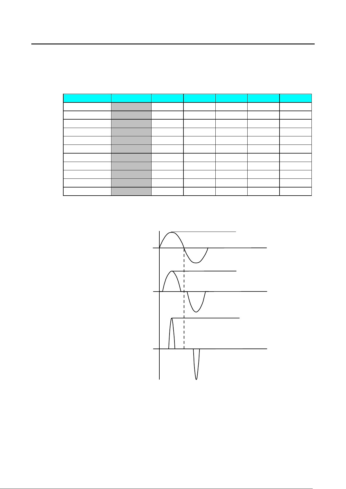
PRODIGIT 3260A Series Operation Manual I - 1
Appendix I 3260A r1.00 Edition Wave Form Data Bank
3260A Series High Power electronic load module provides built-in 11 sets totaling 55 banks which
are described as follows:
BANK A B C D E
sine wave 0 √2 2.0 2.5 3.0 3.5
1 1.5 1.6 1.7 1.8 1.9
2 3.0 3.1 3.2 3.3 3.4
C.F.= 2.0 3 P.F.=-0.85 P.F.=-0.80 P.F.=-0.75 P.F.=-0.70 P.F.=-0.65
C.F.= 2.5 4 P.F.=-0.70 P.F.=-0.65 P.F.=-0.60 P.F.=-0.50 P.F.=-0.40
C.F.= 3.5 5 P.F.=-0.50 P.F.=-0.45 P.F.=-0.40 P.F.=-0.35 P.F.=-0.30
C.F.= 2.0 6 P.F.= 0.85 P.F.= 0.80 P.F.= 0.75 P.F.= 0.70 P.F.= 0.65
C.F.= 2.5 7 P.F.= 0.70 P.F.= 0.65 P.F.= 0.60 P.F.= 0.50 P.F.= 0.40
C.F.= 3.5 8 P.F.= 0.50 P.F.= 0.45 P.F.= 0.40 P.F.= 0.35 P.F.= 0.30
square wave 9 1.0 1.1 1.2 1.3 1.4
DC 10 √2dc 2dc 2.5dc 3.0dc 3.5dc
1.1 C.F. value of sine wave consists of √2~3.5 totaling 15 banks of which the definition is
described in figure below:
Peak
Voltage Wave From
√2
Current Wave Form
when C.F. = 2.0
Current Wave Form
when C.F. = 3.5
2.0Peak
3.5Peak
Page 66
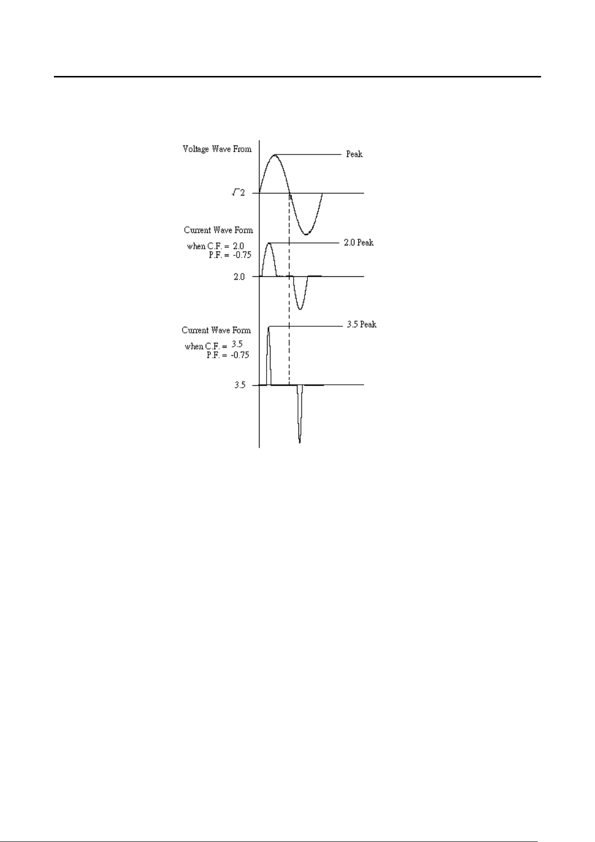
Appendix I - 2 PRODIGIT
1.2 C.F. value of sine wave consists of 2.0~3.5 and P.F. value is -0.85 ~ -0.30 totaling 15
banks of which the definition is described in figure below:
Page 67
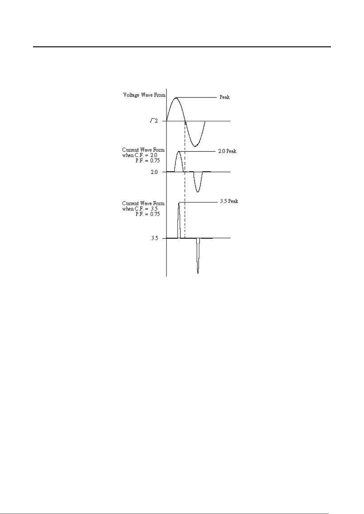
PRODIGIT 3260A Series Operation Manual I -
1.3 C.F. value of sine wave consists of 2.0~3.5 and P.F. value is 0.85 ~ 0.30 totaling 15
banks of which the definition is described in figure below:
3
Page 68
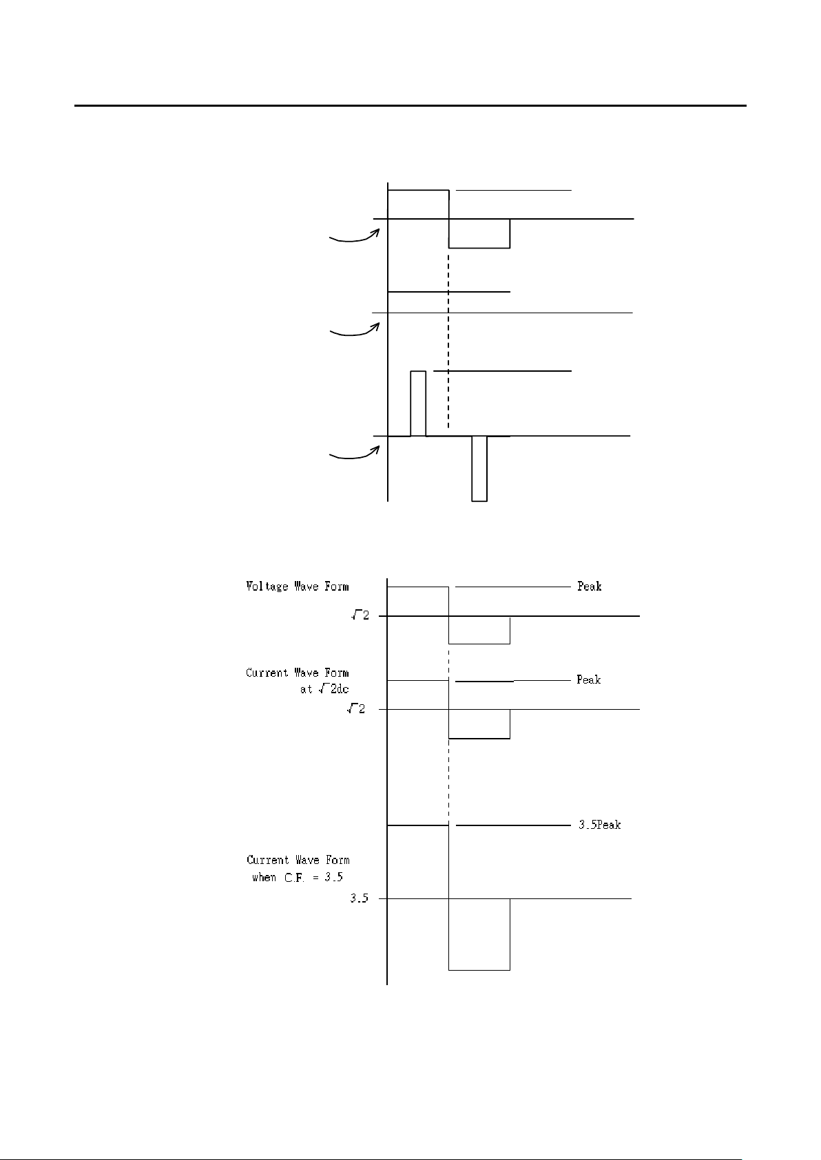
Appendix I - 4 PRODIGIT
1.4 C.F. Value of square wave consists of 1.0~1.4 totaling 5 banks of which the definition
described in figure below:
voltage Wave Form
Zero Crossing
Current Wave Form
when C.F. = 1.0
Zero Crossing
when C.F. = 3.4
Current Wave Form
Zero Crossing
√2
1.0
3.4
Peak
0.707Peak
3.4Peak
1.5 DC Wave form information consists of √2 fold DC level totaling 5 banks of which the
definition described in figure below:
Page 69

PRODIGIT 3260A Series Operation Manual II - 1
Appendix II Setting of AC or DC Electronic Load
3260A Series High Power electronic load is the full function electronic load for AC and DC. The
setting of electronic load for AC or DC depends on the output frequency of U.U.T. The setting is
described as follows:
2.1 Setting of AC Electronic Load
When 3260A series High Power electronic load is attempted to be used for AC, the
frequency of 3260A series High Power electronic load must be set in accordance with
the frequency of U.U.T. Even if the output frequency of U.U.T. is 50 Hz, the frequency
of 3260A series High Power electronic load must be set to 50.0 Hz by means of FREQ
function.
2.2 Setting of DC Electronic Load
When 3260A series High Power electronic load is attempted to used for DC, 3260A
series High Power electronic load must be set to DC. When DC is set, bank function will
fail (fixed on DC, the monitor will not display BANK).
 Loading...