

ProDesign F18E, Fiberglass F18 User Manual
1
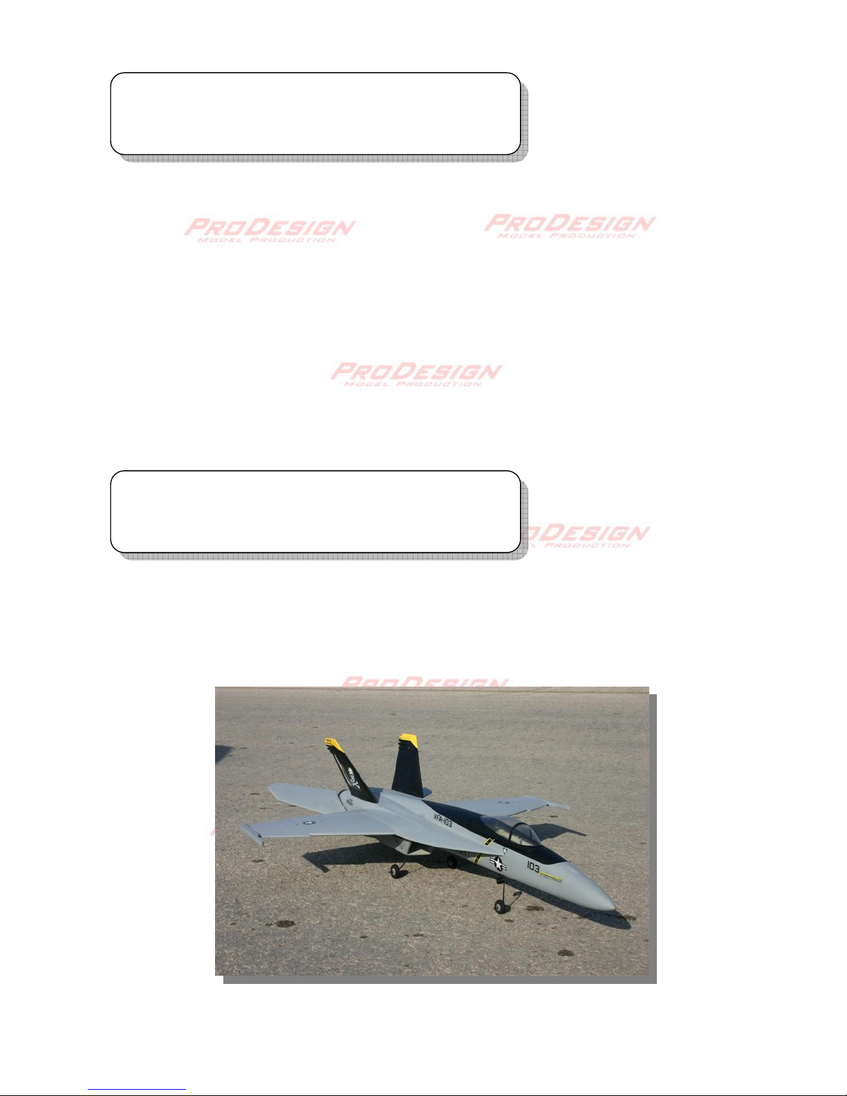
F18E 90mm EDF
High performance Fiberglass F18 for single 90mm electric ducted fan
Specifications are subject to change without notice
Warning !
This model is not a toy and please read the manual carefully before construction and
operating this model aircraft.
Specification
• Flying Weight
~2200g (~4.8 lb)
• Wing span
920mm / 36.2 in.
• Length
1250mm / 49.2 in.
• Rotor diameter
90mm / 3.54 in.
2
Radio system for 4 channels or above
1x Electronic speed controllers for brushless motor
1x 90mm fan-units, EDF shaft adapter diameter 5mm
1x 700-1000W size brushless motors
6-8s Lipo battery for 1600kv brushless motor
4x Servo extension wires
2x Metal gear standard size servo, for elevator
2x 9g servos for ailerons.
5 or 30 minute epoxy, CA Glue
Velcro.
Locktite/ threadlock
Drill , drill bit 2mm, 3mm
Dremel tool
Plier/cutter/ Philip screw driver
2mm , 3mm hex driver
Scissor
Tools needed
Equipment and parts needed
3
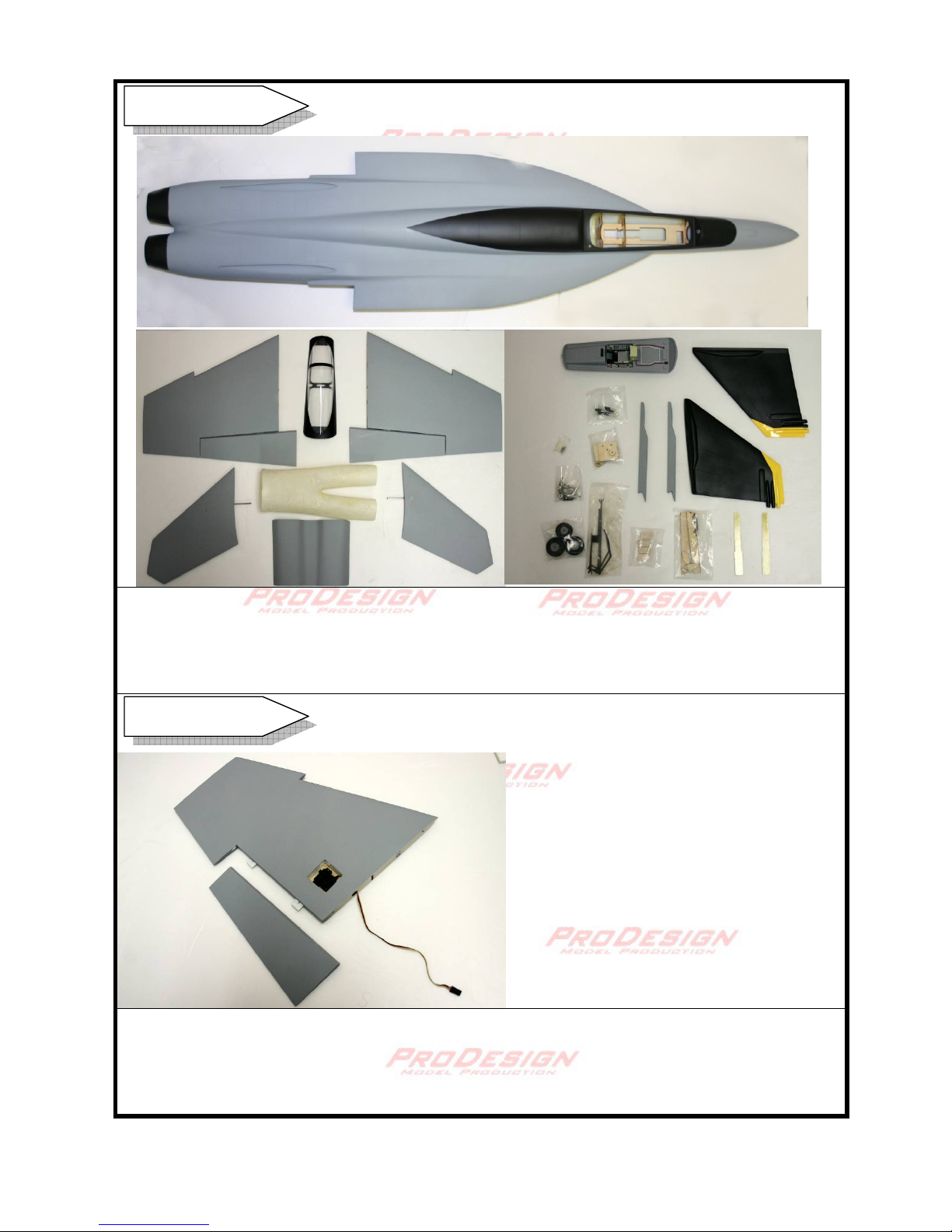
Inside the box : Fuselage, Main wing, Exit ducting, stabilizer, EDF cover, vertical fin, wing
joiner, landing gear and wheel, canopy, cockpit (optional) , hardware bags ( screw, horn,
linkage connector, M3 nut, steering arm, 3mm collar, mounting plate, magnet), Elevator
control hub kit. Waterslide décor. Sidewinder. Pre-painted canopy. Fan unit
Pay attention the R/L main wings are different. The bottom of each wing is slightly flat in the
airfoil. Remove the aileron control surface. Find a pre-cut slot at the underside of the wing
and cut open the film. Insert the aileron servo and pass the wire through the hole. You may
use servo extension wire.
Inside the Box
Main Wing
4
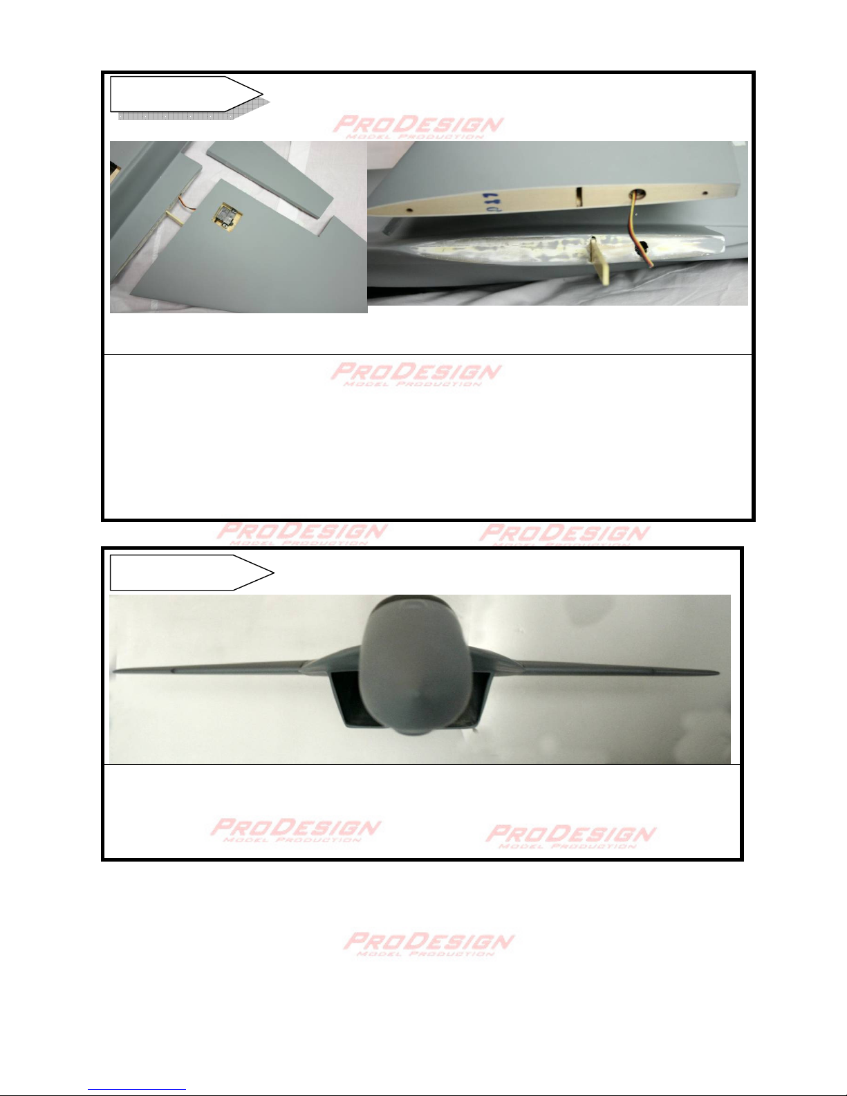
Do not glue the wing at this point. Try fitting the wings to the fuselage with the wing joiner.
The thinner part of the wing joiner goes into the wing. Adjust and orient the joiner such that
both wings are in perfect position. A 5mm hole can be drilled on the side to pass the wire of
the aileron servos.
The wing joiner is made of fiberglass and this guarantee no risk of wing breakage at high
velocity. Sand the surface of the contact area to maximize bonding strength.
Glue the main wings with epoxy, tape or clamp the wings firmly to the fuselage. Support
the wing with blocks if necessary. Check for horizontal and longitudinal symmetry.
Alignment can be confirmed by putting a pitch meter on top of the wing.
Main Wing
Main Wing
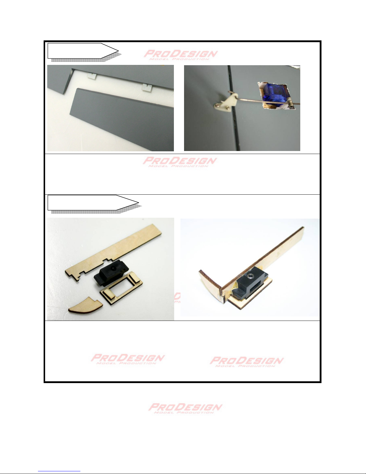
5
Before gluing the aileron servo, center the servo horn by means of a servo tester or with a
receiver/ transmitter. Install the servo with the balsa wood block provided. Mark the horn
insertion and cut a 5mm slot in the aileron and epoxy the control horn. Use CA to connect
the aileron to the wing. Connect the 9.5cm linkage wire to the servo horn.
The full motion elevator needs attention when assemble. The pro-design kit includes a
special designed bearing hub that renders the elevator movement precise and
maintenance free. Four pieces of 3x6x2.5mm ball bearing is provided. Insert each bearing
into the side of the hub. Very little amount of CA is needed to hold the bearing in place. Be
very careful to spread out a drop of CA inside the hub with a toothpick. Spilling of CA inside
the bearing must be avoided. This shows the right elevator control hub.
Elevator Control Hub
Aileron Servo
 Loading...