

Page 1
Installation and
Getting Started Guide
ProCurve Wireless Access Point 530
PoE
Power over Ethernet Devices
www.procurve.com
Page 2

Page 3

ProCurve
Wireless Access Point 530
Installation and Getting Started Guide
Page 4

© Copyright 2006 Hewlett-Packard Development Company,
L.P. The information contained herein is subject to change
without notice.
This document contains proprietary information, which is
protected by copyright. No part of this document may be
photocopied, reproduced, or translated into another language
without the prior written consent of Hewlett-Packard.
Publication Number
5991-2192
May 2006
Applicable Products
ProCurve Wireless Access Point 530 NA (J8986A)
ProCurve Wireless Access Point 530 WW (J8987A)
Disclaimer
HEWLETT-PACKARD COMPANY MAKES NO WARRANTY
OF ANY KIND WITH REGARD TO THIS MATERIAL,
INCLUDING, BUT NOT LIMITED TO, THE IMPLIED
WARRANTIES OF MERCHANTABILITY AND FITNESS
FOR A PARTICULAR PURPOSE. Hewlett-Packard shall not be
liable for errors cont ained herein or for incidental or c onsequential
damages in connection with the furnishing, performance, or use
of this material.
The only warranties for HP products and services are set forth in
the express warranty st atements accompanying such products and
services. Nothing herein should be construed as constituting an
additional w arranty. HP shall not be liable for technical or editor ial
errors or omissions contained herein.
Hewlett-Packard assumes no responsibility for the use or
reliability of its software on equipment that is not furnished by
Hewlett-Packard.
Warranty
See the Customer Support/Warranty booklet included with the
product.
A copy of the specific warranty terms applicable to your HewlettPackard products and replacement parts can be obt ained from your
HP Sales and Service Office or authorized dealer.
Hewlett-Packard Company
8000 Foothills Boulevard, m/s 5552
Roseville, California 95747-5552
http://www.hp.com/go/hpprocurve
Safety
Before installing and operating these products, please read the
“Installation Precautions” in chapter 2, “Installing the Access
Point 530”, and the safety statements in appendix C, “Safety and
EMC Regulatory Statements”.
Page 5

Contents
1 Introducing the ProCurve Wireless Access Point 530
Top of the Access Point . . . . . . . . . . . . . . . . . . . . . . . . . . . . . . . . . . . . . . . . 1-3
LEDs . . . . . . . . . . . . . . . . . . . . . . . . . . . . . . . . . . . . . . . . . . . . . . . . . . . . . . 1-4
Back of the Access Point . . . . . . . . . . . . . . . . . . . . . . . . . . . . . . . . . . . . . . 1-5
Back Panel Covers . . . . . . . . . . . . . . . . . . . . . . . . . . . . . . . . . . . . . . . . . . 1-5
Antennas . . . . . . . . . . . . . . . . . . . . . . . . . . . . . . . . . . . . . . . . . . . . . . . . . . . 1-5
Console Port . . . . . . . . . . . . . . . . . . . . . . . . . . . . . . . . . . . . . . . . . . . . . . . 1-6
Network Port . . . . . . . . . . . . . . . . . . . . . . . . . . . . . . . . . . . . . . . . . . . . . . . 1-6
Power Connector . . . . . . . . . . . . . . . . . . . . . . . . . . . . . . . . . . . . . . . . . . . 1-6
Reset Button . . . . . . . . . . . . . . . . . . . . . . . . . . . . . . . . . . . . . . . . . . . . . . . 1-7
Clear Button . . . . . . . . . . . . . . . . . . . . . . . . . . . . . . . . . . . . . . . . . . . . . . . . 1-8
Auxiliary Port . . . . . . . . . . . . . . . . . . . . . . . . . . . . . . . . . . . . . . . . . . . . . . . 1-8
Access Point Features . . . . . . . . . . . . . . . . . . . . . . . . . . . . . . . . . . . . . . . . . 1-9
2 Installing the Access Point 530
Included Parts . . . . . . . . . . . . . . . . . . . . . . . . . . . . . . . . . . . . . . . . . . . . . . . . 2-1
Installation Procedures . . . . . . . . . . . . . . . . . . . . . . . . . . . . . . . . . . . . . . . . 2-2
Summary . . . . . . . . . . . . . . . . . . . . . . . . . . . . . . . . . . . . . . . . . . . . . . . . . . . 2-2
Installation Precautions: . . . . . . . . . . . . . . . . . . . . . . . . . . . . . . . . . . . . . . 2-3
1. Prepare the Installation Site . . . . . . . . . . . . . . . . . . . . . . . . . . . . . . . . 2-4
2. Verify the Access Point Completes Initialization . . . . . . . . . . . . . . . 2-5
LED Behavior: . . . . . . . . . . . . . . . . . . . . . . . . . . . . . . . . . . . . . . . . . . 2-6
3. Mount the Access Point . . . . . . . . . . . . . . . . . . . . . . . . . . . . . . . . . . . . 2-7
Wall Mounting . . . . . . . . . . . . . . . . . . . . . . . . . . . . . . . . . . . . . . . . . . . 2-7
Standard Electrical Box Mounting . . . . . . . . . . . . . . . . . . . . . . . . . . 2-9
Suspended Ceiling Mounting . . . . . . . . . . . . . . . . . . . . . . . . . . . . . 2-10
Horizontal Surface Mounting . . . . . . . . . . . . . . . . . . . . . . . . . . . . . 2-12
4. Connect the Access Point to a Power Source . . . . . . . . . . . . . . . . . 2-12
5. Connect the Network Cable . . . . . . . . . . . . . . . . . . . . . . . . . . . . . . . . 2-13
Using the RJ-45 Connectors . . . . . . . . . . . . . . . . . . . . . . . . . . . . . . 2-13
6. (Optional) Connect External Antennas to the Access Point . . . . . 2-13
i
Page 6

7. (Optional) Connect a Console to the Access Point 530 . . . . . . . . . 2-14
Terminal Configuration . . . . . . . . . . . . . . . . . . . . . . . . . . . . . . . . . . 2-14
Direct Console Access . . . . . . . . . . . . . . . . . . . . . . . . . . . . . . . . . . . 2-15
Sample Network Topologies . . . . . . . . . . . . . . . . . . . . . . . . . . . . . . . . . . 2-17
Infrastructure Wireless LAN . . . . . . . . . . . . . . . . . . . . . . . . . . . . . . . . . 2-18
Infrastructure Wireless LAN with Roaming . . . . . . . . . . . . . . . . . . . . . 2-19
Wireless Distribution System (WDS) Bridge . . . . . . . . . . . . . . . . . . . . 2-21
Wireless Distribution System (WDS) Repeater . . . . . . . . . . . . . . . . . . 2-23
3 Getting Started With Access Point Configuration
Recommended Minimal Configuration . . . . . . . . . . . . . . . . . . . . . . . . . . 3-1
Using the Command Line Interface . . . . . . . . . . . . . . . . . . . . . . . . . . . . 3-2
To Set the Manager User Name and Password . . . . . . . . . . . . . . . 3-2
To Set the Access Point’s IP Address . . . . . . . . . . . . . . . . . . . . . . . 3-3
To Set the Access Point’s Country Code . . . . . . . . . . . . . . . . . . . . . 3-4
To Configure Radio Settings . . . . . . . . . . . . . . . . . . . . . . . . . . . . . . . 3-4
Where to Go From Here . . . . . . . . . . . . . . . . . . . . . . . . . . . . . . . . . . . . . . 3-8
Using the IP Address for Remote Access Point Management . . . . . 3-9
Starting a Telnet Session . . . . . . . . . . . . . . . . . . . . . . . . . . . . . . . . . . . . . 3-9
Starting an SSH Session . . . . . . . . . . . . . . . . . . . . . . . . . . . . . . . . . . . . . 3-10
Starting a Web Browser Session . . . . . . . . . . . . . . . . . . . . . . . . . . . . . . 3-10
4 Using an External Antenna with the Access Point 530
External Antenna Options . . . . . . . . . . . . . . . . . . . . . . . . . . . . . . . . . . . . . 4-2
Installation Procedures . . . . . . . . . . . . . . . . . . . . . . . . . . . . . . . . . . . . . . . . 4-3
1. Plan the Installation . . . . . . . . . . . . . . . . . . . . . . . . . . . . . . . . . . . . . . . 4-3
2. Mount the Antenna . . . . . . . . . . . . . . . . . . . . . . . . . . . . . . . . . . . . . . . . 4-4
3. Connect Pigtail Cables to the Access Point . . . . . . . . . . . . . . . . . . . . 4-4
4. Configure the Antenna Mode and Type . . . . . . . . . . . . . . . . . . . . . . . 4-6
Setting the Antenna Mode and Type Using the CLI . . . . . . . . . . . . 4-6
Setting the Antenna Mode and Type Using the Web Interface . . . 4-6
ii
Page 7

5 Troubleshooting
Basic Troubleshooting Tips . . . . . . . . . . . . . . . . . . . . . . . . . . . . . . . . . . . . 5-1
Diagnosing with the LEDs . . . . . . . . . . . . . . . . . . . . . . . . . . . . . . . . . . . . . 5-3
Proactive Networking . . . . . . . . . . . . . . . . . . . . . . . . . . . . . . . . . . . . . . . . . 5-5
Hardware Diagnostic Tests . . . . . . . . . . . . . . . . . . . . . . . . . . . . . . . . . . . . 5-6
Testing the Access Point by Resetting It . . . . . . . . . . . . . . . . . . . . . . . . 5-6
Checking the Access Point’s LEDs . . . . . . . . . . . . . . . . . . . . . . . . . 5-6
Checking Event Messages . . . . . . . . . . . . . . . . . . . . . . . . . . . . . . . . . 5-6
Testing Twisted-Pair Cabling . . . . . . . . . . . . . . . . . . . . . . . . . . . . . . . . . . 5-7
Testing Access Point-to-Device Network Communications . . . . . . . . 5-7
Testing End-to-End Network Communications . . . . . . . . . . . . . . . . . . 5-7
Restoring Custom and Factory Default Configurations . . . . . . . . . . 5-8
Downloading New Access Point Software . . . . . . . . . . . . . . . . . . . . . . 5-10
HP Customer Support Services . . . . . . . . . . . . . . . . . . . . . . . . . . . . . . . . 5-10
Before Calling Support . . . . . . . . . . . . . . . . . . . . . . . . . . . . . . . . . . . . . . 5-10
A Specifications
Physical . . . . . . . . . . . . . . . . . . . . . . . . . . . . . . . . . . . . . . . . . . . . . . . . . . A-1
Electrical . . . . . . . . . . . . . . . . . . . . . . . . . . . . . . . . . . . . . . . . . . . . . . . . . A-1
Environmental . . . . . . . . . . . . . . . . . . . . . . . . . . . . . . . . . . . . . . . . . . . . A-1
Connectors . . . . . . . . . . . . . . . . . . . . . . . . . . . . . . . . . . . . . . . . . . . . . . . . A-2
Safety . . . . . . . . . . . . . . . . . . . . . . . . . . . . . . . . . . . . . . . . . . . . . . . . . . . . A-2
EMC Compliance (Class B) . . . . . . . . . . . . . . . . . . . . . . . . . . . . . . . . . . A-2
Radio Signal Certification . . . . . . . . . . . . . . . . . . . . . . . . . . . . . . . . . . . A-2
Immunity . . . . . . . . . . . . . . . . . . . . . . . . . . . . . . . . . . . . . . . . . . . . . . . . . A-2
Wireless . . . . . . . . . . . . . . . . . . . . . . . . . . . . . . . . . . . . . . . . . . . . . . . . . . A-3
Receiver Sensitivity . . . . . . . . . . . . . . . . . . . . . . . . . . . . . . . . . . . . . . . . . A-4
B Access Point Port and Network Cables
Access Point Ports . . . . . . . . . . . . . . . . . . . . . . . . . . . . . . . . . . . . . . . . . B-1
Twisted-Pair Cables . . . . . . . . . . . . . . . . . . . . . . . . . . . . . . . . . . . . . . . . B-1
iii
Page 8

Twisted-Pair Cable/Connector Pin-Outs . . . . . . . . . . . . . . . . . . . . . . . B-2
Straight-Through Twisted-Pair Cable for
10 Mbps or 100 Mbps Network Connections . . . . . . . . . . . . . . . . . . . . B-3
Cable Diagram . . . . . . . . . . . . . . . . . . . . . . . . . . . . . . . . . . . . . . . . . B-3
Pin Assignments . . . . . . . . . . . . . . . . . . . . . . . . . . . . . . . . . . . . . . . B-3
Crossover Twisted-Pair Cable for
10 Mbps or 100 Mbps Network Connection . . . . . . . . . . . . . . . . . . . . . B-4
Cable Diagram . . . . . . . . . . . . . . . . . . . . . . . . . . . . . . . . . . . . . . . . . B-4
Pin Assignments . . . . . . . . . . . . . . . . . . . . . . . . . . . . . . . . . . . . . . . B-4
C Safety and EMC Regulatory Statements
Safety Information . . . . . . . . . . . . . . . . . . . . . . . . . . . . . . . . . . . . . . . . . . . C-1
EMC Regulatory Statements . . . . . . . . . . . . . . . . . . . . . . . . . . . . . . . . . . C-9
D Recycle Statements
Waste Electrical and Electronic Equipment (WEEE) Statements D-1
Index
iv
Page 9
Introducing the ProCurve
1
Wireless Access Point 530
Introducing the ProCurve
Wireless Access Point 530
The ProCurve Wireless Access Point 530 is an enterprise-class, dual-radio
802.11b/g and 802.11a/b/g access point that offers maximum flexibility in
deployment and optimum throughput for high-density usage areas.
The access point provides comprehensive security and management features
and is capable of supporting all types of wireless stations in the same coverage
area. The unit includes internal diversity antennas for both radios and also
connectors for attaching a variety of external antenna options. Mounting
options for the unit include horizontal surface, wall, suspended ceiling T-rail,
and plenum space.
ProCurve Wireless Access Point 530 NA (J8986A)
ProCurve Wireless Access Point 530 WW (J8987A)
Throughout this manual, this access point will be abbreviated as the
Access Point 530.
The Access Point 530 has one 10/100Base-TX RJ-45 port. This port also
supports Power over Ethernet (PoE) based on the IEEE 802.3af standard. The
access point supports wireless connectivity at speeds up to 54 Mbps based on
the IEEE 802.11g and IEEE 802.11a standards.
1-1
Page 10

Introducing the ProCurve Wireless Access Point 530
This access point is designed to be used primarily for connecting wireless
stations to an enterprise network. This access point allows wireless stations
to connect directly to each other, or to connect to other computers or network
resources located on the wired network.
This chapter describes your Access Point 530 including:
■ Top and back of the access point
■ Access point features
Introducing the ProCurve
Wireless Access Point 530
1-2
Page 11

Introducing the ProCurve Wireless Access Point 530
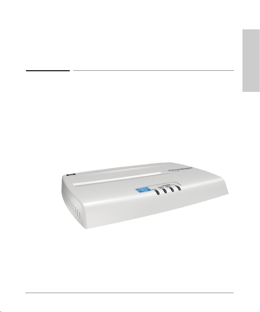
Top of the Access Point
Back Panel Covers
Top of the Access Point
ProCurve Wireless Access Point 530
Wireless Access Point 530
Introducing the ProCurve
Indicator Panel
Power LED
Ethernet LEDWireless LED
1-3
Page 12

Introducing the ProCurve Wireless Access Point 530
Top of the Access Point
LEDs
Table 1-1. Access Point LEDs
Access Point
LEDs
Power
(green)
Introducing the ProCurve
Wireless Access Point 530
LAN
(green)
Radio 1 (11b/g)
Radio 2 (11a/b/g)
(green)
State Meaning
On The access point is receiving power.
Off The access point is NOT receiving power.
Off The RJ-45 port has no network cable connected, or is not receiving a link signal.
Blinking or OnThe RJ-45 port has a link indication from a 10 Mbps or 100 Mbps device and is
transmitting or receiving traffic. The LED blinking rate is proportional to the traffic
rate. If there is no traffic, the blinking rate will be once every five seconds. As the
traffic rate i ncreases, the blinking ra te also increases until the LED is solid on, which
indicates there no available bandwidth on the port.
Off The wireless interface is disabled, either through the access point console or the
Web browser interface.
Blinking or OnThe wireless interface is enabled and transmitting or receiving traffic. The LED
blinking rate is proportional to the traffic rate. If there is no traffic, the blinking rate
will be once every five seconds. As the traffic rate increases, the blinking rate also
increases until the LED is solid on, which indicates there no available bandwidth
on the interface.
1-4
Page 13
Introducing the ProCurve Wireless Access Point 530
Back of the Access Point
ProCurve Wireless Access Point 530
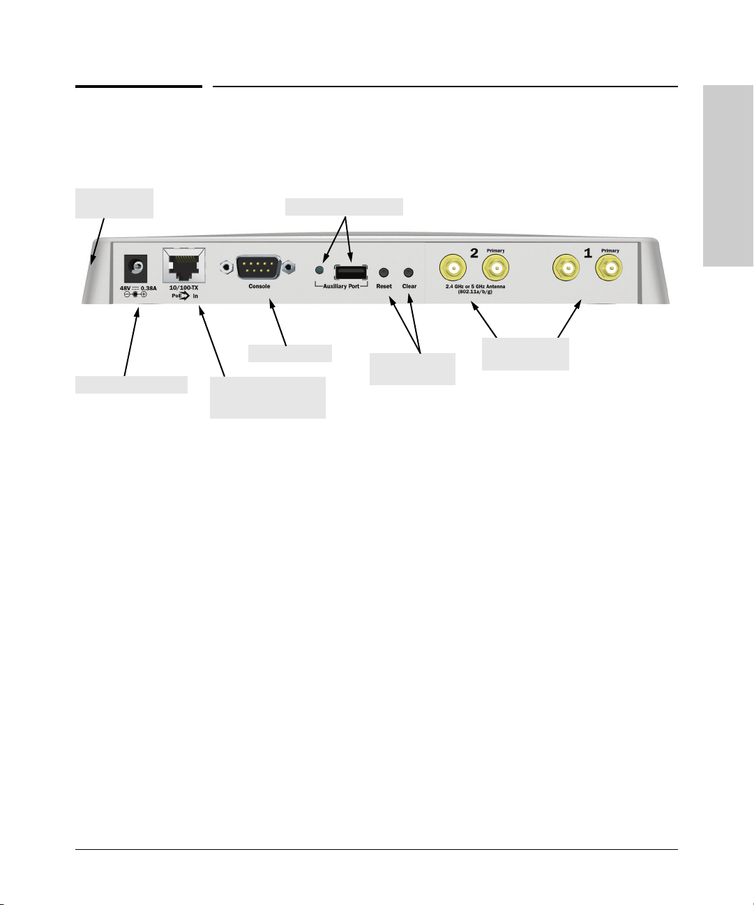
Back of the Access Point
Wireless Access Point 530
Introducing the ProCurve
Lock
(on side panel)
DC power connector
Auxiliary port and LED
Console port
Network port
10/100Base-TX RJ-45
port and PoE input
Reset and Clear
buttons
External Antenna
connectors
Back Panel Covers
The access point’s ports and connectors on the back of the unit can be
protected by two removable plastic covers. One covers the Console port, Clear
and Reset buttons, RJ-45 port, and DC power connector, while allowing
twisted-pair and power cables to pass through. The other cover protects the
external antenna connectors when they are not in use.
Antennas
The access point includes internal diversity antennas for wireless communications. A diversity antenna system uses two identical antennas to receive and
transmit signals, helping to avoid multipath fading effects. When receiving,
the access point checks both antennas and selects the one with the strongest
signal. When transmitting, it will continue to use the antenna previously
selected for receiving. The access point never transmits from both antennas
at the same time.
1-5
Page 14

Introducing the ProCurve Wireless Access Point 530
Back of the Access Point
The access point also supports connectors for various external antenna
options that offer extended radio range and specific radio coverage patterns.
For further information, see chapter 4, “Using an External Antenna with the
Access Point 530”.
Lock
The access point includes a Kensington security slot on the side panel, marked
Introducing the ProCurve
Wireless Access Point 530
with the lock symbol ( ). You can prevent unauthorized removal of the
access point by wrapping the Kensington security cable (not provided) around
an unmovable object, inserting the lock into the slot, and turning the key.
Console Port
This port connects a console to the access point using a serial cable. This
connection is described under “Connect a Console to the Access Point” in
chapter 2, “Installing the Access Point 530”. The console can be a PC or
workstation running a VT-100 terminal emulator, or a VT-100 terminal.
Network Port
The access point includes one 10/100Base-TX port. This port uses the “HP Auto
MDIX” feature, which means that you can use either straight-through or
crossover twisted-pair cables to connect the access point to a switch or
workstation.
Refer to the following section for information on supplying power to the
access point through its RJ-45 port from a network device, such as a switch,
that provides Power over Ethernet (PoE).
Power Connector
The Access Point 530 does not have a power switch; it is powered on when
connected to the AC power adapter, and the power adapter is connected to
an active AC power source. The access point's power adapter automatically
adjusts to any voltage between 100--240 volts and either 50 or 60 Hz. There are
no voltage range settings required.
Caution Use only the AC power adapter supplied with the access point. Use of other
adapters, including adapters that came with other ProCurve Networking
products, may result in damage to the equipment.
1-6
Page 15

Introducing the ProCurve Wireless Access Point 530
Back of the Access Point
The access point may also receive Power over Ethernet (PoE) from a switch
or other network device that supplies power over the network cable based on
the IEEE 802.3af standard.
Note that if the access point is connected to a PoE source device and also
connected to a local power source through the AC power adapter, PoE will
be disabled.
Reset Button
This button is used to reset the hardware or restore the factory defaults:
■ To Reset the Access Point While it is Powered On – When the Reset
button is pressed for about one second all the LEDs turn off, then after
another second the LEDs start to blink rapidly. Releasing the button when
the LEDs are blinking rapidly clears any temporary error conditions that
may have occurred and restarts the access point initialization.
■ To Restore Custom Default Configuration – When pressed with the
Clear button in a specific pattern, any configuration changes you may have
made through the access point console or the Web browser interface are
removed, and the customer-specified default configuration is restored to
the access point. For the specific method to restore the customer default
configuration, see “Restoring Custom and Factory Default Configurations” in chapter 5, “Troubleshooting” of this guide.
■ To Restore Factory Default Configuration – When pressed with the
Clear button in a specific pattern, any configuration changes you may have
made through the access point console or the Web browser interface are
removed, and the factory default configuration is restored to the access
point. For the specific method to restore the factory default configuration,
see “Restoring Custom and Factory Default Configurations” in chapter 5,
“Troubleshooting” of this guide.
Wireless Access Point 530
Introducing the ProCurve
Note The system, password, custom default, and factory default reset functions can
be disabled by the access point’s software. For more information, see the
Management and Configuration Guide, which is on the Documentation
CD-ROM that came with your access point and also on the ProCurve Networking Web site at http://www.procurve.com.
1-7
Page 16

Introducing the ProCurve Wireless Access Point 530
Back of the Access Point
Clear Button
This button is used for these purposes:
■ Deleting the Password - When pressed by itself for at least one second,
the button resets the Manager password to the factory default setting for
all of the access point’s interfaces. Use this feature if you have misplaced
the password and need management access.
■ To Restore Custom Default Configuration – When pressed with the
Introducing the ProCurve
Wireless Access Point 530
Reset button in a specific pattern, any configuration changes you may
have made through the access point console or the Web browser interface
are removed, and the customer-specified default configuration is restored
to the access point. For the specific method to restore the customer
default configuration, see “Restoring Custom and Factory Default Configurations” in chapter 5, “Troubleshooting” of this guide.
■ Restoring Factory Default Configuration - When pressed with the
Reset button in a specific pattern, any configuration changes you may
have made through the console, the Web browser interface, and SNMP
management are removed, and the factory default configuration is
restored to the access point. For the specific method to restore the factory
default configuration, see “Restoring Custom and Factory Default Configurations” in chapter 5, “Troubleshooting” of this guide.
1-8
Auxiliary Port
The Auxiliary port is reserved for future use.
Page 17

Introducing the ProCurve Wireless Access Point 530
Access Point Features
Access Point Features
The wireless features of the Access Point 530 include:
■ dual-radio design with IEEE 802.11b/g and IEEE 802.11a/b/g radios
■ supports up to 16 Service Set IDentifier (SSID) interfaces
■ independent security and VLAN settings per SSID interface
■ supports up to 256 wireless stations per radio interface
■ IEEE 802.11a/b/g compliant – interoperable with multiple vendors
■ precise control over signal transmission power and data rate
■ advanced security through 64/128/152-bit WEP encryption, Wi-Fi
Protected Access (WPA and WPA2), IEEE 802.1X, remote authentication
via a RADIUS server, and MAC address filtering features to protect your
sensitive data and authenticate only authorized users to your network
■ remote logging of system messages
■ time synchronization via SNTP server for message logs
■ wireless bridging between access points
■ neighbor access point detection
■ Quality of Service (QoS) support through Wi-Fi Multimedia (WMM) and
Spectralink Voice Priority (SVP)
■ auto channel selection – simplifies deployment by testing all available
channels and selecting the best channel based on signal-to-noise ratio
■ international country configuration – select the appropriate country and
the access point automatically configures radio operation to match regulatory requirements (model J8987A only)
Wireless Access Point 530
Introducing the ProCurve
The other basic features of the Access Point 530 include:
■ one 10/100Base-TX RJ-45 port
■ supports Power over Ethernet based on the IEEE 802.3af standard
■ full-duplex operation for the 10/100 RJ-45 port
■ easy management of the access point through several available interfaces:
• console interface—a full featured, easy to use, VT-100 terminal
interface that is especially good for out-of-band access point management and for Telnet or Secure Shell access to the access point
• Web browser interface—an easy to use built-in graphical interface
that can be accessed from common Web browsers (includes support
for secure HTTP connections)
1-9
Page 18

Introducing the ProCurve Wireless Access Point 530
Access Point Features
• SNMP—a network management application such as HP ProCurve
Manager can manage the access point via the Simple Network
Management Protocol (SNMP) from a network management station
(supports SNMP versions 1, and 2c)
■ support for IEEE 802.1Q-compliant VLANs (as specified for each station
in the RADIUS server) so that wireless stations can join the appropriate
logical grouping for the network user’s needs
■ support for Identity Driven Management and RADIUS assigned VLANs
Introducing the ProCurve
Wireless Access Point 530
■ RADIUS Accounting for logging user activity on the network
■ support for many advanced features to enhance network performance—
for a description, see the Management and Configuration Guide, which
is on the Documentation CD-ROM that is included with your access point.
■ download of new access point software for product enhancements or
software updates
■ upload and download of access point configuration files
1-10
Page 19

Installing the Access Point 530
The Access Point 530 is easy to install. It comes with an accessory kit that
includes a bracket for mounting the access point on a wall or to a suspended
ceiling T-rail. The bracket is designed to allow mounting the access point in a
variety of locations and orientations.
This chapter shows you how to install your Access Point 530.
Included Parts
The Access Point 530 has the following components shipped with it:
■ ProCurve Wireless Access Point 530 Installation and Getting Started
Guide (5991-2192), this manual
■ ProCurve Product Documentation CD-ROM
(contains PDF file copies of the documentation for the Access Point 530,
including the Management and Configuration Guide)
■ Customer Support/Warranty booklet
■ Accessory kit (5070-1657)
• four 5/8-inch number 12 wood screws to attach the access point to a
wall
• four plastic wall plugs for mounting on a brick or concrete wall
• four rubber feet
■ Mounting bracket (5188-4682)
■ AC power adapter (5188-3767)
■ AC power cord, one of the following:
2
Access Point 530
Installing the
United States/Canada/Mexico
Continental Europe
United Kingdom/Hong Kong/Singapore
Australia/New Zealand
Japan
China
Denmark
Switzerland
8120-0740
8121-0731
8121-0739
8121-0730
8121-0736
8121-0742
8121-0733
8121-0738
2-1
Page 20

Installing the Access Point 530
Installation Procedures
Installation Procedures
Summary
Follow these easy steps to install your access point. The rest of this chapter
provides details on these steps.
1. Prepare the installation site (page 2-4). Make sure that the physical
environment into which you will be installing the access point is properly
prepared, including having the correct network cabling ready to connect
to the access point and having an appropriate location for the access
point. Please see page 2-2 for some installation precautions.
2. Verify that the access point completes its system initialization
(page 2-5). This is a simple process of plugging the access point into a
power source, or connecting it to a switch that provides Power over
Ethernet, and observing that the LEDs on the access point’s top panel
Installing the
Access Point 530
indicate correct access point operation.
3. Mount the access point (page 2-7). The Access Point 530 can be
mounted on a wall, on a suspended ceiling T-rail, or on a horizontal
surface.
2-2
4. Connect power to the access point (page 2-12). Once the access
point is mounted, plug it into a nearby main power source, or connect it
to a switch that provides Power over Ethernet.
5. Connect to the network (page 2-13). Using the appropriate network
cable, connect the access point to a network connection point, such as a
switch. The network connection can also be used to provide power to the
access point through its PoE feature.
6. Connect a console to the access point (optional—page 2-14). You
may wish to modify the access point’s configuration, for example, to
configure an IP address so it can be managed using a Web browser or
through a Telnet session. Configuration changes can be made easily by
using a console cable to connect a PC to the access point’s console port.
At this point, your access point is fully installed. See the rest of this chapter if
you need more detailed information on any of these installation steps.
Page 21

Installing the Access Point 530
Installation Procedures
Installation Precautions:
Follow these precautions when installing your Access Point 530:
Cautions ■ Make sure that the power source circuits are properly grounded, then use
the power adapter supplied with the access point to connect it to the
power source.
■ You can alternatively power the access point through a network connec-
tion to a switch or other network connection device that provides Power
over Ethernet. However, note that if the access point is connected to a
power source using its AC power adapter, Power over Ethernet is
disabled.
■ Use only the AC power adapter supplied with the access point. Use of
other adapters, including adapters that came with other ProCurve
Networking products, may result in damage to the equipment.
■ When using the access point's AC power adapter, note that the AC outlet
should be near the access point and should be easily accessible in case
the access point must be powered off.
■ Ensure that the access point does not overload the power circuits, wiring,
and over-current protection. To determine the possibility of overloading
the supply circuits, add together the ampere ratings of all devices installed
on the same circuit as the access point and compare the total with the
rating limit for the circuit. The maximum ampere ratings are usually
printed on devices near the AC power connectors.
■ When using the AC power adapter, do not install the access point in an
environment where the operating ambient temperature might exceed
40° C (104° F). When using PoE power, do not install the access point in
an environment where the operating ambient temperature might exceed
50° C (122° F)
■ Make sure the air flow around the sides of the access point is not
restricted.
Access Point 530
Installing the
2-3
Page 22

Installing the Access Point 530
Installation Procedures
1. Prepare the Installation Site
■ Cabling Infrastructure - Ensure that the cabling infrastructure meets
the necessary network specifications. See the following table for cable
types and lengths, and see appendix B, “Access Point Port and Network
Cables” for more information.
Table 2-1. Summary of Cable Types to Use With the Access Point
Port Type Cable Type Length Limits
Twisted-Pair Cables
10/100Base-TX • 10 Mbps operation:
Category 3, 4, or 5, 100-ohm unshielded
twisted-pair (UTP)
• 100 Mbps operation:
Category 5, 100-ohm UTP cable.
Installing the
Access Point 530
■ Installation Location - Before installing the access point, plan its loca-
100 meters
Note: Since the 1 0Base-T operation is through
the 10/100Base-TX port on the access point, if
you ever want to upgrade the ports on other
devices to 100Base-TX, it would be best to
cable the 10/100Base-TX port on the access
point initially with category 5 cable.
The 10/100-Base-TX port on the
Access Point 530 uses the “HP Auto MDIX”
feature, which means that you can use either
straight-through or crossover twisted-pair
cables to connect the access point to a switch
or workstation.
tion and orientation relative to other devices and equipment:
• Try to place the access point in the center of your wireless network.
Normally, the higher you place the antennas, the better the performance. You may need to reposition the access point after testing the
signal strength on several wireless stations to ensure that the access
point’s location provides optimal reception throughout the service
area.
• At the back of the access point, leave at least 7.6 cm (3 inches) of
space for the twisted-pair cabling and the power cord.
• On the sides of the access point, leave at least 7.6 cm (3 inches) for
cooling.
2-4
Page 23

Installing the Access Point 530
Installation Procedures
2. Verify the Access Point Completes Initialization
Before mounting the access point in its network location, you should first
verify that it is working properly by plugging it into a power source, or
connecting it to a switch that provides Power over Ethernet, and verifying that
it completes its system initialization.
1. Connect a network cable from a PoE source device (such as a switch) to
the RJ-45 port on the back of the access point, or connect the supplied
power adapter to the power connector on the back of the access point,
and then into a properly grounded electrical outlet.
Access Point 530
Installing the
Or connect power adap ter
to the power connector
Connect network
cable to PoE switch
Note The Access Point 530 does not have a power switch. It is powered on when
the power adapter is connected to the access point and to a power source, or
when a network cable is connected to the access point and to a network device
that provides Power over Ethernet. For safety, when connecting to an electrical outlet, the power outlet should be located near the access point.
Use only the AC power adapter supplied with the access point. Use of other
adapters, including adapters that came with other ProCurve Networking
products, may result in damage to the equipment.
2-5
Page 24

Installing the Access Point 530
Installation Procedures
2. Check the LEDs on the access point as described below.
Power LED
Wireless LEDs Ethernet LED
When the access point is powered on, it performs its system initialization.
The system initialization takes between 30 seconds and one minute to
complete.
Installing the
Access Point 530
LED Behavior:
During the system initialization:
• The Power LED first turns on immediately, then the Power, LAN,
Radio 1, and Radio 2 LEDs turn on and off several times during phases
of the initialization.
When the system initialization completes successfully:
•The Power LED remains on green.
•The LAN and Radio LEDs on the top of the access point go into their
normal operational mode:
– If the RJ-45 network port and radio interfaces are connected to
active network devices, the LEDs should be blinking at a rate
proportional to the traffic rate. If there is no network activity, the
LEDs should still be blinking at approximately 5 second intervals.
– If the RJ-45 network port is not connected to an active network
device and the radio interfaces are disabled, the LEDs should be
off.
2-6
If the LED display is different than what is described above, the system
initialization has not completed correctly. Refer to chapter 5, “Troubleshooting” for diagnostic help.
Page 25

Installing the Access Point 530
Installation Procedures
3. Mount the Access Point
After you have verified that the access point completes its system initialization, you are ready to mount the access point in a stable location. The
Access Point 530 can be mounted in these ways:
■ on a wall
■ on a standard electric receptacle box
■ on a suspended ceiling T-rail
■ on a horizontal surface
Wall Mounting
You can mount the access point on a wall as shown in the illustrations on the
next page.
Caution The access point should be mounted only to a wall or wood surface that is at
least 1/2-inch plywood or its equivalent.
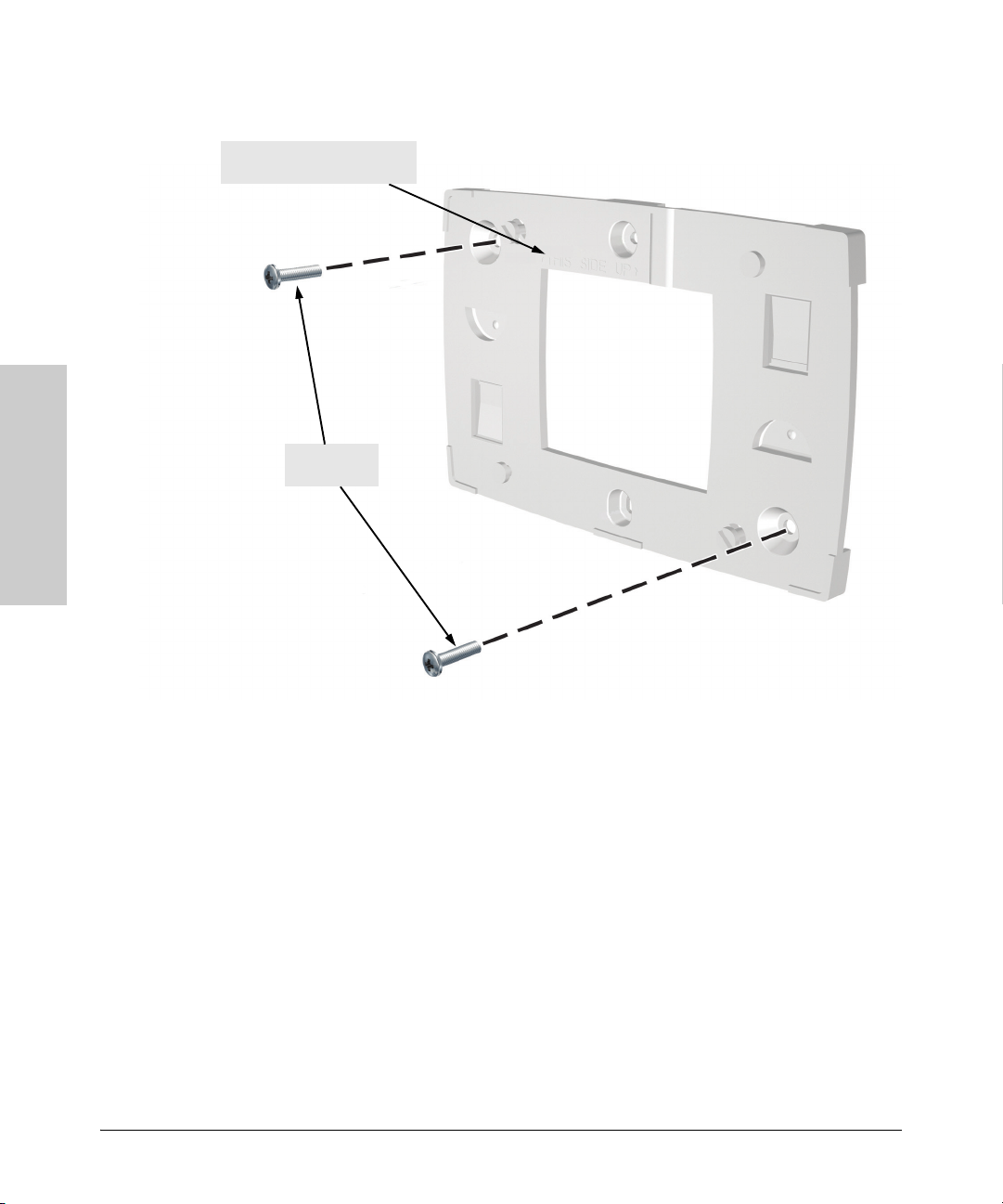
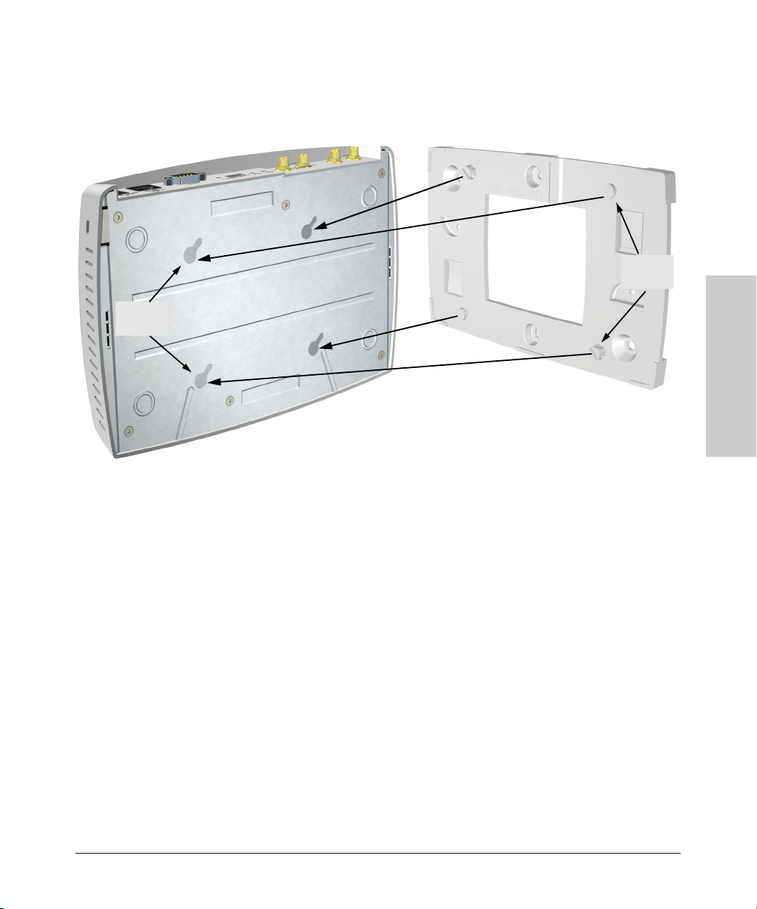
1. Position the mounting bracket on the wall, and mark the two corner holes.
The orientation shown in the following figure is the most secure position
for mounting the access point. Look for the marking “THIS SIDE UP” on
the bracket. Do not mount the access point with its ports and connectors
pointing down.
2. To mount the access point on a plastered brick or concrete wall, first drill
two holes 22 mm deep and 3.5 mm in diameter, and press the two included
wall plugs firmly into the drilled holes until they are flush with the surface
of the wall.
3. Position the mounting bracket over the drilled holes, then insert the two
5/8-inch number 12 wood screws in the corner holes and tighten down the
screws.
4. There are four recess slots on the bottom of the access point that match
up with four protrusions on the mounting bracket, as shown in the
following figures.
Slide the access point down onto the bracket so that the four protrusions
on the bracket enter the four recess slots on the bottom of the access
point. Push the access point firmly down onto the bracket until clicks into
a locked position.
Access Point 530
Installing the
5. To prevent unauthorized removal of the access point, you can use a
Kensington Slim MicroSaver security cable (not included) to attach the
access point to an immovable object.
2-7
Page 26
Installing the Access Point 530
Installation Procedures
Look for the “THIS SIDE UP”
marking in this area
5/8-inch
wood screws
Installing the
Access Point 530
Mounting the Bracket on a Wall
2-8
Page 27
Installing the Access Point 530
Installation Procedures
Sliding the Access Point onto the Bracket
Mounting
points
Mounting
slots
Standard Electrical Box Mounting
You can mount the access point on a standard electric receptacle box as shown
in the illustration on the next page.
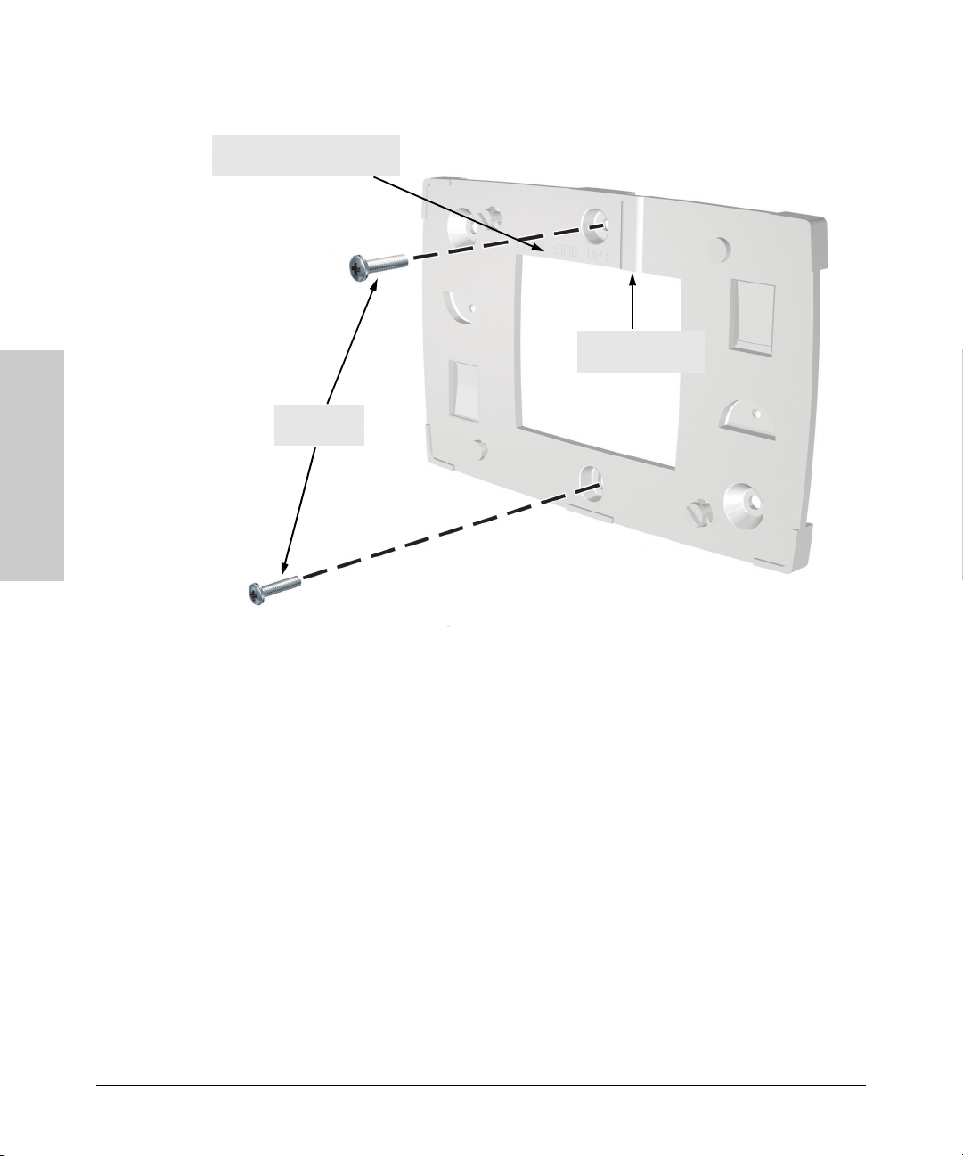
1. Position the mounting bracket on the electrical box with the two center
holes positioned over the screw holes on the box. The orientation shown
in the following figure is the most secure position for mounting the access
point. Look for the marking “THIS SIDE UP” on the bracket. Do not mount
the access point with its ports and connectors pointing down.
2. Insert two 6-32 machine screws in the center holes and tighten down the
screws.
3. There are four recess slots on the bottom of the access point that match
up with four protrusions on the mounting bracket, as shown in the
illustration for normal wall mounting.
Access Point 530
Installing the
Slide the access point down onto the bracket so that the four protrusions
on the bracket enter the four recess slots on the bottom of the access
point. Push the access point firmly down onto the bracket until clicks into
a locked position.
2-9
Page 28
Installing the Access Point 530
Installation Procedures
Look for the “THIS SIDE UP”
marking in this area
6-32 machine
screws
Installing the
Access Point 530
Mounting the Bracket on a Standard Electrical Box
Route cable through
this groove
2-10
Suspended Ceiling Mounting
You can mount the access point on a suspended ceiling T-rail as shown in the
illustrations on the next page.
1. Attach the access point to its mounting bracket by sliding the unit down
onto the bracket so that the four protrusions on the bracket enter the four
recess slots on the bottom of the access point. Push the access point firmly
down onto the bracket until clicks into a locked position.
2. Position the access point with its mounting bracket at a slight angle to the
suspended ceiling T-rail.
3. Push the access point firmly onto the T-rail, then turn counterclockwise
until the rail snaps into the clips on the access point’s bracket.
Page 29
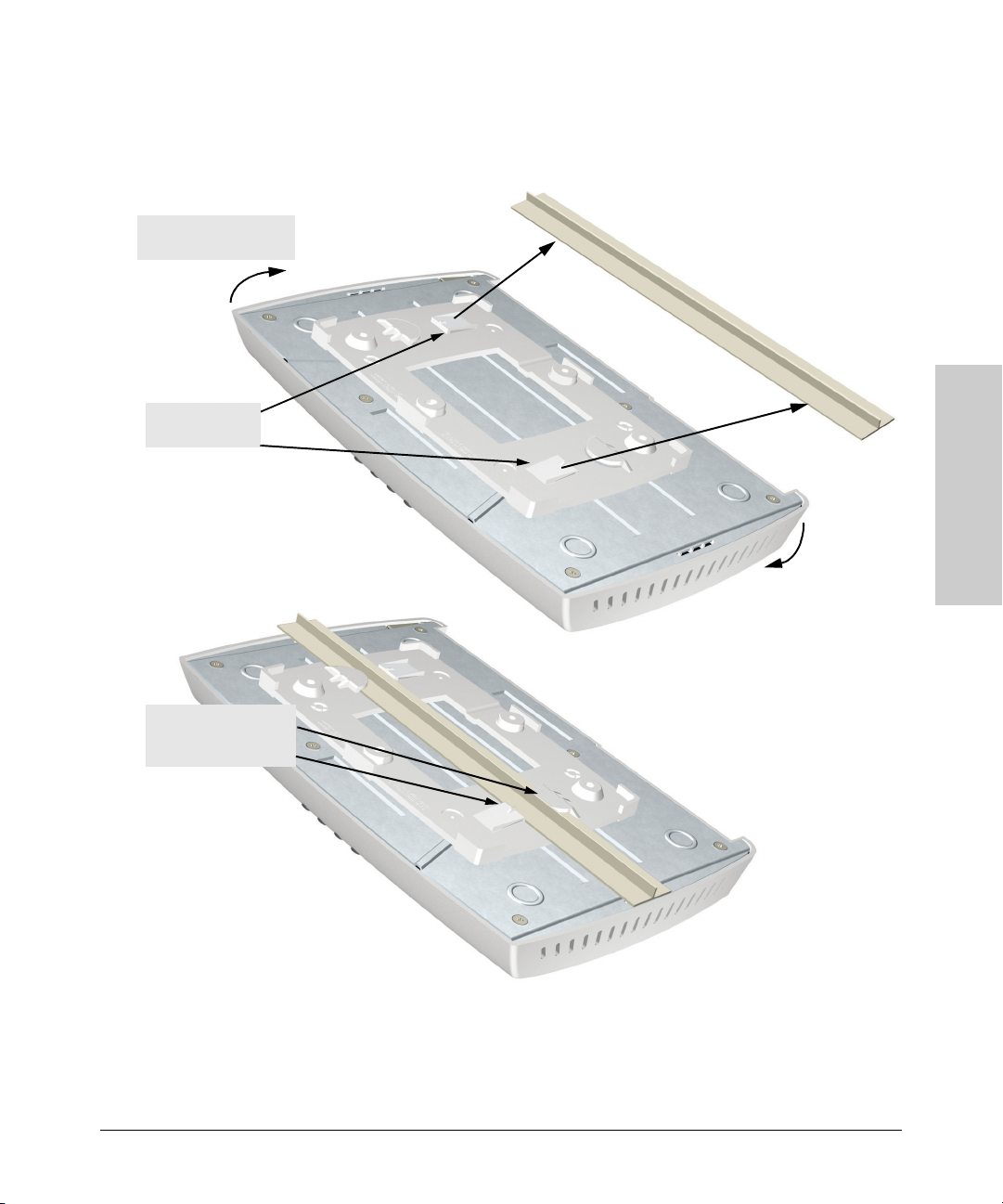
2. Turn access point until
clips secure T-rail
Installing the Access Point 530
Installation Procedures
Mounting the Access Point on a Suspended Ceiling T-Rail
1. Push T-rail onto
bracket clips
One side of T-rail held
under tab, the other
side help by clip
Access Point 530
Installing the
2-11
Page 30

Installing the Access Point 530
Installation Procedures
Horizontal Surface Mounting
Place the access point on a table or other horizontal surface. The access point
accessory kit provides rubber feet that can be used to help keep the access
point from sliding on the surface.
Attach the rubber feet to the four corners on the bottom of the access point
within the embossed circles. Use a sturdy surface in an uncluttered area. You
may want to secure the networking cable and access point’s power cord to
the table leg or other part of the surface structure to help prevent tripping over
the cords.
Caution Make sure the air flow is not restricted around the sides of the access point.
4. Connect the Access Point to a Power Source
1. Plug the included power adapter into the access point’s power connector
Installing the
Access Point 530
and into a nearby AC power source.
Or, alternatively, connect the Ethernet port on the access point to a switch
or other network device that provides Power over Ethernet.
2. Re-check the LEDs during the system initialization. See “LED Behavior”
on page 2-6.
2-12
Page 31

Installing the Access Point 530
Installation Procedures
5. Connect the Network Cable
Connect the network cable, described under “Cabling Infrastructure”
(page 2-4), from the network device or your patch panel to the RJ-45 port on
the access point.
Using the RJ-45 Connectors
To c o nn ec t :
Push the RJ-45 plug into the RJ-45
port until the tab on the plug clicks
into place. When power is on for the
access point and for the connected
device, the 10/100Base-TX link LED
should light to confirm a powered-on
device (for example, a switch) is at
the other end of the cable.
If the 10/100Base-TX link LED does
not go on when the network cable is
connected to the port, see “Diagnosing with the LEDs” in chapter 5,
“Troubleshooting”.
To disconnect:
Press the small tab on the plug and
pull the plug out of the port.
Cable:
• Category 3, 4, or 5 for 10 Mbps ports (UTP)
• Category 5 or better for 100 Mbps ports (UTP)
Maximum distance: 100 meters
RJ-45
connector
Access Point 530
Installing the
6. (Optional) Connect External Antennas to the Access
Point
If you intend to use optional external antennas with the access point, connect
them by following the instructions in chapter 4, “Using an External Antenna
with the Access Point 530”.
2-13
Page 32

Installing the Access Point 530
Installation Procedures
7. (Optional) Connect a Console to the Access Point 530
The Access Point 530 has a full-featured, easy to use console interface for
performing access point management tasks, including the following:
■ modify the access point’s configuration to optimize access point perfor-
mance, enhance network traffic control, and improve network security
■ download new software to the access point
■ set a Manager password to control access to the access point from the
console, Web browser interface, and network management stations
The console can be accessed through these methods:
■ Out-of-Band: Use a serial cable for connecting a PC or VT-100 terminal
to be used as a console directly to the access point.
■ In-Band: Access the console using Telnet or Secure Shell (SSH) from a
PC on the network, and a VT-100 terminal emulator. This method requires
that you first configure the access point with an IP address and subnet
mask by using either out-of-band console access or through DHCP. For
Installing the
Access Point 530
more information on IP addressing and on starting a Telnet or SSH session,
see chapter 3, “Getting Started With Access Point Configuration”, and the
Management and Configuration Guide, which is on the Documentation
CD-ROM that came with your access point.
The Access Point 530 can simultaneously support one out-of-band console
session through the Console Port and four in-band Telnet or SSH console
sessions.
Note For information on using the Web browser interface to configure the access
point, refer to the Management and Configuration Guide.
Terminal Configuration
To connect a console to the access point, configure the PC terminal emulator
as a DEC VT-100 (ANSI) terminal or use a VT-100 terminal, and configure either
one to operate with these settings:
• 9600 baud
• 8 data bits, 1 stop bit, no parity, and flow control set to None
• For the Windows Terminal program, also disable (uncheck) the “Use
Function, Arrow, and Ctrl Keys for Windows” option
• For the Hilgraeve HyperTerminal program, select the “Terminal keys”
option for the “Function, arrow, and ctrl keys act as” parameter
You can only attach to the console using these configuration settings.
2-14
Page 33

Direct Console Access
To connect a console to the
access point, follow these steps:
Installing the Access Point 530
Installation Procedures
1. Connect the PC or terminal
Console port
to the access point’s Console
port using a DB-9 female-tofemale serial cable. (If your
PC or terminal has a 25-pin
serial connector, first attach
Console cable
(not supplied)
a 9-pin to 25-pin straightthrough adapter at one end
of the console cable.)
The Console cable is
described below. A nullmodem cable or an HP
PC running a terminal
emulator program, or
a VT-100 terminal
serial cable, part number
5184-1894 (shipped with
many ProCurve Networking
switches), may be used.
Access Point 530 serial port pin and signalling details
Access Point 530 Pin Assignment Pin Number Access Point Signal (DTE)
1
DB-9 male
6
5
9
1
2
3
4
5
6
7
8
9
Reserved
RXD (input)
TXD (output)
Reserved
GND
Reserved
RTS (output)
CTS (input)
Reserved
Access Point 530
Installing the
Connection to PC serial ports also requires a crossover (null-modem)
cable with a female DB-9 connector on both ends. Terminal connections
will vary, requiring either a DB-9 or DB-25 connector, male or female.
Serial cable options between an Access Point 530 and a PC terminal are
shown in the following table.
2-15
Page 34

Installing the Access Point 530
Installation Procedures
Note: As indicated in the following table, some of the wires should not
be connected. If you do connect the wires that are labeled “Reserved”,
you might get unexpected results with some terminals.
Serial interface signal directions
DB-9 (DTE)
Access Point 530
1
2
3
4
5
6
7
8
9
Installing the
Access Point 530
2. Turn on the terminal or PC’s power and, if using a PC, start the PC terminal
program.
Reserved
Reserved
GND
Reserved
Reserved
DB9 (DTE)
Terminal or PC
1
2
3
4
5
6
7
8
9
DB-9 (DTE)
Access Point 530
1
2
3
4
5
6
7
8
9
Reserved
Reserved
Reserved
Reserved
GND
DB-25 (DTE)
Terminal or PC
8
3
2
20
7
6
4
5
22
3. Enter admin at the Username: prompt, and admin at the Password: prompt.
You will then see the access point console command (CLI) prompt, for
example:
ProCurve Access Point 530#
If you want to continue with console management of the access point at this
time, see chapter 3, “Getting Started With Access Point Configuration” for
some basic configuration steps. For more detailed information, refer to the
Management and Configuration Guide, which is on the Documentation
CD-ROM that came with your access point.
2-16
Page 35

Installing the Access Point 530
Sample Network Topologies
Sample Network Topologies
This section shows you a few sample network topologies in which the
Access Point 530 is implemented. The access point is designed to be deployed
in an integrated configuration with wired Ethernet LANs, providing network
access to wireless stations in the wireless coverage area.
The access point’s radios can be configured to operate in any of the following
modes:
■ infrastructure wireless LAN
■ infrastructure wireless LAN with roaming
■ Wireless Distribution System (WDS) bridge
■ Wireless Distribution System (WDS) repeater
For more topology information, see the ProCurve Networking Web site at:
http://www.procurve.com.
Access Point 530
Installing the
2-17
Page 36

Desktop PC
Infrastructure Wireless LAN
The Access Point 530 is designed to provide access to a wired LAN for wireless
stations. An integrated wired and wireless LAN is called an Infrastructure
configuration. A Basic Service Set (BSS) consists of a group of wireless PC
users and an access point that is directly connected to the wired LAN. Each
wireless PC in a BSS can communicate with any computer in its wireless
group, or access other computers or network resources in the wired LAN
through the access point.
The infrastructure configuration extends the accessibility of wireless PCs to
the wired LAN and can be used for access to central network resources, or
for connections between mobile workers, as shown in the following figure.
Wired LAN Extension
File
Server
Switch
to Wireless Stations
Access Point 530
Desktop PC
Wireless Station
Notebook PC
Wireless Station
Page 37

Installing the Access Point 530
Sample Network Topologies
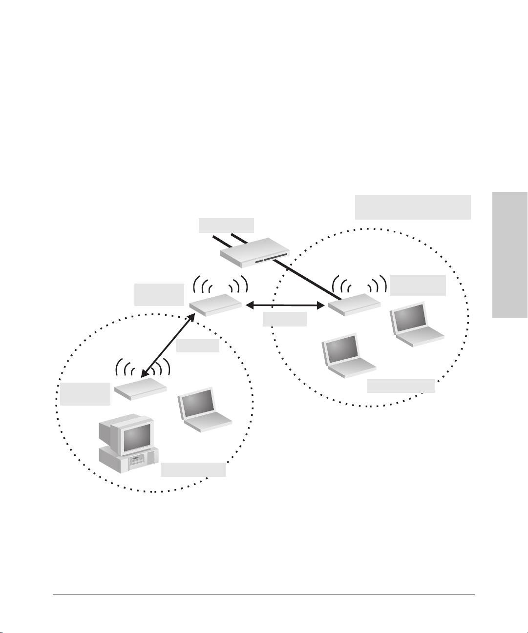
Infrastructure Wireless LAN with Roaming
The Basic Service Set (BSS) defines the communications domain for each
access point and its associated wireless stations. The BSS ID is a 48-bit binary
number based on the access point’s wireless MAC address, and is set automatically and transparently as stations associate with the access point. The BSS
ID is used in frames sent between the access point and its stations to identify
traffic in the service area.
The BSS ID is only set by the access point, never by its stations. The stations
only need to set the Service Set Identifier (SSID) that identifies the wireless
network provided by one or more access points. The SSID can be manually
configured by the stations, can be detected in an access point’s beacon, or can
be obtained by querying for the identity of the nearest access point.
A wireless infrastructure can also support roaming for mobile workers. More
than one access point can be configured to create an Extended Service Set
(ESS). By placing the access points so that a continuous coverage area is
created, wireless users within this ESS can roam freely. All ProCurve
Networking wireless network cards, adapters, and access points within a
specific ESS must be configured with the same SSID.
Access Point 530
Installing the
2-19
Page 38

Installing the Access Point 530
Sample Network Topologies
File
Server
Seamless Roaming for
Wireless Stations
Desktop PC
Switch
Wireless Station
Switch
Wireless Station
Access Point 530
Installing the
Access Point 530
Access Point 530
<BSS2>
<ESS>
<BSS1>
Wireless Station
2-20
Page 39

Installing the Access Point 530
Sample Network Topologies
Wireless Distribution System (WDS) Bridge
The IEEE 802.11 standard defines a WIreless Distribution System (WDS) for
bridge connections between access points (BSS areas). The access point
radios can be configured to use WDS to forward traffic over secure links
between Access Point 530 units. This enables the access point to provide
wireless bridge extensions to network segments that are remote or isolated,
such as between buildings on separate sites.
Up to six WDS bridge links can be specified for an access point radio. One
Access Point 530 must serve as the “root bridge” and be connected to the main
core of the wired LAN. This “root bridge” access point can then provide WDS
links for up to six other Access Point 530 units.
The access point supports WDS bridge links on either Radio 1 (802.11a/b/g)
or Radio 2 (802.11b/g) and can be used with various external antennas to offer
flexible deployment options. Although a radio can implement WDS links and
support wireless stations, for performance reasons it is better to dedicate one
radio for WDS bridge links and use the other radio to service wireless stations,
as shown in the following figure.
Access Point 530
Installing the
2-21
Page 40

Installing the Access Point 530
Sample Network Topologies
WDS Wireless Bridge Links
Between Access Points
Wired LAN in
Building 1
Wired LAN in
Building 2
WDS Bridge
Link
AP530
Installing the
Access Point 530
Wireless Stations
Wireless Stations
AP530
2-22
Page 41
Installing the Access Point 530
Sample Network Topologies
Wireless Distribution System (WDS) Repeater
The Access Point 530 can also operate as a WDS bridge “repeater” to extend
the range of links to other access points or wireless stations. The access point
can support up to six WDS repeater links.
Operating as a wireless repeater, the access point may not have an Ethernet
link to a wired LAN. When the access point operates as a wireless repeater
only half the normal throughput is possible. This is because the access point
has to receive and then re-transmit all data on the same radio channel.
WDS Wireless Repeater Links
Between Access Points
Wired LAN
Access Point 530
Installing the
Remote
AP530
AP530
“repeater”
Wireless Stations
Connected
AP530
WDS Link
WDS Link
Wireless Stations
2-23
Page 42

Installing the Access Point 530
Sample Network Topologies
— This page is intentionally unused. —
Installing the
Access Point 530
2-24
Page 43

Getting Started With Access Point Configuration
This chapter is a guide for using the access point’s console to quickly assign
an Internet Protocol (IP) address and subnet mask to the access point, set a
manager password, and, optionally, configure other basic features.
For more information on using the access point’s console and the Web browser
interface, please see the Management and Configuration Guide, which is on
the Documentation CD-ROM that came with your access point.
Recommended Minimal Configuration
In the factory default configuration, the access point is configured as a DHCP
client. If the access point fails to obtain an IP address from the DHCP server,
it uses its default static IP address of 192.168.1.10. If this address is not
compatible with your network, then the access point can only be managed
through a direct console connection. To manage the access point through inband (networked) access, you should configure the access point with an IP
address and subnet mask compatible with your network. Also, you should
change the default Manager password that controls access to the console and
Web browser interface. Other parameters can be left at their default settings
or you can configure them with values you enter.
3
Getting Started With Access
Point Configuration
Caution A correct country code must be set for the country in which you operate the
access point, so that it uses the correct authorized radio channels for wireless
network devices. The country code for the ProCurve Wireless Access Point
530 NA (J8986A) is preset to “US” and can only be changed from “US” to the
country codes for either Canada or Mexico.
The ProCurve Wireless Access Point 530 WW (J8987A) has no preset country
code and must be configured before you can enable radio communications
for the access point. Refer to“To Set the Access Point’s Country Code” on
page 3-4 for information on setting the country code.
Many other features can be configured through the access point’s console
interface to optimize the access point’s performance, to enhance your control
of the network traffic, and to improve network security. Once an IP address
3-1
Page 44

Getting Started With Access Point Configuration
has been configured on the access point, these features can be accessed more
conveniently through a remote Telnet or Secure Shell (SSH) session, or
through the access point’s Web browser interface.
For more information on IP addressing, refer to “Configuring IP Settings” in
the Management and Configuration Guide.
Note By default, the access point is configured to acquire an IP address configura-
tion from a DHCP server. To use DHCP instead of the manual method
described in this chapter, see “Configuring Ethernet Settings” in the Manage-
ment and Configuration Guide, which is on the Documentation CD-ROM that
came with your access point.
Using the Command Line Interface
The quickest and easiest way to minimally configure the access point for
management and password protection in your network is to use a direct
console connection to the access point, start a console session, and access
the command line interface (CLI).
To Set the Manager User Name and Password
Getting Started With Access
Management access to the access point’s Web and CLI interface is controlled
through a single user name and password. The Manager user name and
password allows full read/write privileges for the Web and CLI.
1. Using the method described in the preceding chapter, connect a terminal
device to the access point, and press
[Enter] to initiate the console connec-
tion.
2. Type admin for the default Manager user name and also admin for the
Point Configuration
default password, then press
the access point’s model number.
ProCurve-AP-530 login: admin
Password:
ProCurve Access Point 530#
[Enter]. The CLI prompt appears displaying
3. Type configure to enter global configuration mode.
ProCurve Access Point 530#configure
ProCurve Access Point 530(config)#
3-2
Page 45

Getting Started With Access Point Configuration
4. Type password manager password to create a password for the Manager,
where password can consist of between 1 and 32 alphanumeric characters
and is case sensitive.
ProCurve Access Point 530(config)#password manager 1AB2F
ProCurve Access Point 530(config)#
To Set the Access Point’s IP Address
By default, the access point is configured to automatically receive IP
addressing from a Dynamic Host Configuration Protocol (DHCP) server.
However, if you are not using a DHCP server to configure IP addressing, use
the CLI to manually configure the IP values.
1. From the global configuration mode, type interface ethernet to access the
Ethernet interface-configuration mode.
ProCurve Access Point 530(config)#interface ethernet
ProCurve Access Point 530(ethernet)#
2. Type show ip to display the access point’s default IP configuration,
including IP address, subnet mask, and default gateway. The following
illustration shows the default settings.
ProCurve Access Point 530(ethernet)# show ip
IP Address Information:
System Host Name ProCurve-AP-530
IP Address 192.168.1.10
Subnet Mask 255.255.255.0
Default Gateway not set
DHCP Client Enabled
DNS Information (Obtained from DHCP):
Domain Name Suffix not set
Primary DNS Server not set
Secondary DNS Server not set
ProCurve Access Point 530(ethernet)#
3. To manually assign an IP address, type ip address ip-address netmask,
where ip-address is the access point’s IP address and netmask is the
network mask for the network. If managing the access point from another
subnet, you must also set the default gateway with the ip default-gateway
gateway command, where gateway is the address of the default gateway
router. Check with your system administrator to obtain an IP address that
is compatible with your network.
ProCurve Access Point 530(ethernet)#ip address 192.168.2.2 255.255.255.0
ProCurve Access Point 530(ethernet)#ip default-gateway 192.168.2.254
ProCurve Access Point 530(ethernet)#
Getting Started With Access
Point Configuration
3-3
Page 46

Getting Started With Access Point Configuration
To Set the Access Point’s Country Code
The ProCurve Wireless Access Point 530 NA (J8986A) is preset with a country
code of “US,” allowing the use of radio channels 1 - 11 for 802.11b/g operation
and radio channels 36 - 64 and 149 - 161 for 802.11a operation, as supported
under FCC regulations. The country code can be changed from “US” to only
the country codes for either Canada or Mexico.
The ProCurve Wireless Access Point 530 WW (J8987A) does not have a preset
country code. You must set the country code for the country in which you
operate the access point. The country code can only be set using the CLI.
Caution The ProCurve Wireless Access Point 530 requires the user to select the appro-
priate Country Code during the initial set up. Once the country code has been
set, the access point will automatically limit the available channels, ensuring
compliant operation in the selected country. Incorrectly entering the country
code may result in illegal operation and may cause harmful interference to
other systems. The user is obligated to ensure that the radio is operating in
accordance with channel, power, indoor/outdoor restrictions and license
requirements for the intended country.
Note that once you have set the country code, it can only be changed by
restoring the factory default settings as described under “Restoring Custom
and Factory Default Configurations” on page 5-8.
Getting Started With Access
Select the two-character code for your country (refer to the Management and
Configuration Guide for a full list of codes), then enter the country command
followed by your country code; for example, gb for Great Britain.
ProCurve Access Point 530#country gb
ProCurve Access Point 530#
Point Configuration
To Configure Radio Settings
The access point supports up to 16 Service Set IDentifier (SSID) interfaces
per physical radio interface. Most radio parameters apply globally to all
configured SSID interfaces. For each SSID interface, different security
settings, VLAN assignments, and other parameters can be applied.
Each SSID interface can be configured individually to enable or inhibit the
broadcast of the SSID in the radio’s beacon frames. SSID interfaces that are
not configured to broadcast the SSID are “hidden,” only being advertised in
probe responses.
3-4
Page 47

Getting Started With Access Point Configuration
When access point configuration parameters are changed, wireless stations
may be temporarily disconnected until the new configuration parameter is
enabled. This includes any changes to a WLAN or radio parameter.
Note The radios are disabled if the Country Code is not set. Once the Country Code
is set, the radios can be enabled.
1. From any command level, type the show radio command followed by the
radio number to display the radio’s configuration, including the radio
mode, radio channel, and operation status. The following illustration
shows the default settings.
ProCurve Access Point 530# show radio 1
Description Radio 1 - 802.11g
Base MAC 00:14:C2:A5:3C:00 Status Disabled
Mode 802.11g Channel-Policy Auto
Channel 1 WLANs Supported 16
Preamble long CTS Protection Enabled
Slot-time short Beacon-Interval(K-us) 100
TX-Power(dBm) 0 Power Reduction(dB) 0
Antenna Mode diversity Antenna(s) In Use internal
RTS-Threshold 2347 Fragment-Threshold 2346
WMM QoS Enabled Inactivity Timeout 1800
Max Stations 256
Rate-Limiting (Disabled)
Rate-Limit(packets/second) 50 Burst-Limit(packets/second) 75
AP-Detection (Disabled)
Periodic Scan Duration(ms) 30 Periodic Scan Interval(sec) 10
List Max Entries 255 List Expiration Time(sec) 3600
ProCurve Access Point 530#
Getting Started With Access
Point Configuration
2. Type configure to enter global configuration mode, and then type radio 1
to access the wireless interface-configuration mode for radio 1.
ProCurve Access Point 530#configure
ProCurve Access Point 530(config)#radio 1
ProCurve Access Point 530(radio1)#
3. Set the channel through which the access point’s radio 1 (802.11b/g)
communicates with its wireless stations. The default setting is to statically
set the operating channel number. Type channel-policy static channel,
where channel can be from 1 to 14, depending on the wireless regulations
specified by your country. Otherwise, type channel-policy auto to have the
access point automatically select the least congested channel.
ProCurve Access Point 530(radio1)#channel-policy static 11
ProCurve Access Point 530(radio1)#
3-5
Page 48

Getting Started With Access Point Configuration
4. To set the primary Service Set Identifier (SSID) for the access point. Type
wlan 1 to enter SSID interface configuration for the primary SSID interface. Then type ssid identifier, where identifier can consist of up to 32
alphanumeric characters and is case sensitive.
ProCurve Access Point 530(radio1)# wlan 1
ProCurve Access Point 530(radio1-wlan1)# ssid AP530
ProCurve Access Point 530(radio1-wlan1)#
5. To enable radio 1 for the access point, type exit to return to the configuration mode for radio 1, then type enable to enable the radio.
ProCurve Access Point 530(radio1-wlan1)# exit
ProCurve Access Point 530(radio1)# enable
ProCurve Access Point 530(radio1)#
6. To configure the access point’s radio 2 interface, type radio 2 and repeat
steps 1 to 4. Note that when the radio 2 interface mode is set to 802.11a,
the available channels are 36 to 165, depending on the country setting.
7. To save all configuration settings from the running configuration file to
the startup configuration file, type write memory from any command level.
ProCurve Access Point 530(radio1-wlan1)# write memory
ProCurve Access Point 530(radio1-wlan1)#
Getting Started With Access
Point Configuration
3-6
Page 49

Getting Started With Access Point Configuration
Here is some information on the basic IP address and wireless configuration
parameters. For more information on these parameters, see the Management
and Configuration Guide, which is on the Documentation CD-ROM that came
with your access point:
Parameter Default
Username admin The name of the manager.
Password admin The password for the manager.
IP Address 192.168.1.10 IP address compatible with your network.
Subnet Mask 255.255.255.0 Subnet mask compatible with your network.
Default Gateway not set IP address of the next-hop gateway node for network traffic that needs to
be able to reach off-subnet destinations.
Radio 1 Mode 802.11g The operating mode for Radio 1.
Radio 2 Mode 802.11a The operating mode for Radio 2.
SSID Radio 1 - SSID 1
Radio 2 - SSID 2
Channel Policy Auto The radio channel through which an access point radio communicates
Wireless Operation Enabled Wireless operation is automatically enabled after you have set the country
Note: The IP address and subnet mask assigned for the access point must be compatible with the IP addressing used
in your network. For more information on IP addressing, see the Management and Configuration Guide, which is on
the Documentation CD-ROM that came with your access point.
The Service Set Identifier (SSID) for the access point interface, which is
broadcast in the beacon frames.
with its wireless stations. When attempting to connect, most wireless
stations automatically set their radio channel to the same channel used
by the access point.
code.
Getting Started With Access
Point Configuration
3-7
Page 50

Getting Started With Access Point Configuration
Where to Go From Here
The above procedure, using the CLI, configured your access point with a
Manager password, IP address, and subnet mask. As a result, with the proper
network connections, you can now manage the access point from a PC
equipped with Telnet or a Secure Shell client, or a Web browser interface. The
above procedure also configured the primary Service Set Identifier (SSID),
the radio channel, and enabled wireless operation. Your wireless stations can
now access the network by setting their SSID and radio channel to the same
values used by the access point. Note that some wireless stations can be
configured to scan all of the radio channels for an access point and the SSID.
Some basic information on managing your access point is included in the next
section. For more information on the console and Web browser interfaces,
and all the features that can be configured on the Access Point 530, please see
the Management and Configuration Guide, which is on the Documentation
CD-ROM that came with your access point.
To Recover from a Lost Manager Password: If you cannot start a console session because of a lost manager password, you can reset the password to the factory default by getting physical access to the access point and pressing and holding the Clear button for more than one second.
Getting Started With Access
Point Configuration
3-8
Page 51

Using the IP Address for Remote Access Point Management
Getting Started With Access Point Configuration
Using the IP Address for Remote Access
Point Management
With your Access Point 530, you can use the access point’s IP address to
manage the access point from any PC that is on the same subnet as the access
point. You can use either a Telnet or Secure Shell (SSH) session, or a standard
Web browser to manage the access point.
Note To provide more security for the access point, management interfaces that are
not required can be disabled. This includes the Web, Telnet, and SSH, as well
as the serial console port. You can also disable the ability to reset the access
point using the Clear and Reset buttons. For more information, see the
Management and Configuration Guide, which is on the Documentation
CD-ROM that came with your access point.
Starting a Telnet Session
To access the access point through a Telnet session, follow these steps:
1. Make sure the access point is configured with an IP address and that the
access point is reachable from the PC that is running the Telnet session
(for example, use a ping command to the access point’s IP address).
2. Start the Telnet program on a PC that is on the same subnet as the access
point and connect to the access point’s IP address.
Example:
telnet 192.168.1.19
3. Enter the user name and password. (The default user name is admin and
the default password is also admin. You will then see the access point’s
console command (CLI) prompt, for example:
ProCurve-AP-530 login: admin
Password:
ProCurve Access Point 530#
Enter ? to see a list of commands that can be executed at the prompt.
Entering any command followed by ? displays a list of options that are
available at that point in the command entry.
Getting Started With Access
Point Configuration
3-9
Page 52

Getting Started With Access Point Configuration
Using the IP Address for Remote Access Point Management
Starting an SSH Session
To access the console through an SSH session, SSH v2.0 client software must
be installed on the management station PC. Note that after boot up, the access
point’s SSH server needs about two minutes to generate host encryption keys.
The SSH server is disabled while the keys are being generated.
Note The access point supports only SSH version 2.0.
To access the access point through an SSH session, follow these steps:
1. Make sure the access point is configured with an IP address and that the
access point is reachable from the PC that is running the SSH session (for
example, use a ping command to the access point’s IP address).
2. Start the SSH client program on a PC that is on the same subnet as the
access point and connect to the access point’s IP address.
Example:
ssh 192.168.1.19
3. Enter the Manager user name and password. (The default Manager user
name is admin and the default password is also admin. You will then see
the access point’s console command (CLI) prompt, for example:
Getting Started With Access
ProCurve-AP-530 login: admin
Password:
ProCurve Access Point 530#
Starting a Web Browser Session
Your Access Point 530 can be managed through a graphical interface that you
Point Configuration
3-10
can access from any PC or workstation on the same subnet as the access point.
Open a compatible browser and type the access point’s IP address as the URL.
(See “Using the Command Line Interface” on page 3-2 for information on
setting the IP address.) No additional software installation is required to make
this interface available; it is included in the access point’s onboard software.
The operating and Web systems support recommended to manage the access
point through the browser interface are as follows:
■ Microsoft Internet Explorer version 5.5 or 6.x (with up-to-date patch level
for either major version) on Microsoft Windows XP or Microsoft Windows
2000
■ Netscape Mozilla 1.7.x on Redhat Linux version 2.4
■ Mozilla/5.0 (Windows; U; Windows NT 5.1; rv:1.7.3) Gecko/20041001
Firefox/0.10.1
Page 53

Using the IP Address for Remote Access Point Management
Getting Started With Access Point Configuration
The administration Web browser must have JavaScript enabled to support the
interactive features of the administration interface. It must also support HTTP
uploads to use the firmware upgrade feature.
A typical Web browser interface screen is shown in the next illustration.
For more information on using the Web browser interface, please see the
Management and Configuration Guide, which is on the Documentation
CD-ROM that came with your access point.
A help system is also available for the Web browser interface. Click the HELP
link in the upper-right corner of the screen.
Getting Started With Access
Point Configuration
3-11
Page 54

— This page is intentionally unused. —
Page 55

4
Using an External Antenna with the Access Point 530
The Access Point 530 provides a variety of external antenna options for
extending the radio range and shaping the coverage area. These antennas offer
a number of different mounting locations, including indoor or outdoor, wall,
ceiling, or radio mast.
This chapter shows you how to install an external antenna for your
Access Point 530.
Note When both Radio 1 and Radio 2 are configured to use 802.11b/g mode, then
Radio 2 must be connected to an external antenna. Radio 2 can only operate
using the internal antenna when configured for 802.11a mode.
Professional
Installation
Required
Only the ProCurve antennas listed in this guide are permitted to be connected
to the Access Point 530. You must use the appropriate antennas, cables, and
where applicable, surge arrestors, for your given region. You are responsible
for verifying local regulations or legislation that may impose restrictions on
the use of specific antenna and cable combinations. For this reason, you must
consult with a professional installer who is trained in RF installation and
knowledgeable in the local regulations prior to connecting an external
antenna to your wireless radio product. It is the responsibility of the end user
to ensure that the antenna installation complies with the local radio regulations. For more information on external antennas, see the ProCurve
Networking Web site at: http://www.procurve.com.
4-1
with the Access Point 530
Using an External Antenna
Page 56

Using an External Antenna with the Access Point 530
External Antenna Options
External Antenna Options
The Access Point 530 external antenna options are outlined in the following
table:
Table 4-1. Summary of External Antennas to Use With the Access Point 530
Antenna Type Part Number Mounting Horizontal
Beamwidth (3dB)
2.4 GHz 5 dBi indoor/outdoor
omnidirectional
2.4 GHz 8 dBi outdoor
omnidirectional
2.4 GHz 14 dBi indoor/outdoor Yagi
(for point-to-point operation)
2.4 / 5 GHz 3 dBi indoor
omnidirectional diversity
2.4 / 5 GHz 7 dBi indoor/outdoor
directional
5 GHz 6 dBi indoor/outdoor
omnidirectional
5 GHz 14 dBi indoor/outdoor
directional (for point-to-multipoint
operation)
J8441A Ceiling or mast 360 Degrees 31 Degrees
J8444A Mast 360 Degrees 12 Degrees
J8448B Articulating wall or
mast mount
J8997A Ceiling grid 360 Degrees 70 Degrees
J8999A Flush wall mount with
integrated
articulating feature
J8998A Ceiling, mast or
I-beam
J9000A Flush wall mount with
integrated
articulating feature
34 Degrees 30 Degrees
68 Degrees 66 Degrees
360 Degrees 17 Degrees
29 Degrees 27 Degrees
Ver tical
Beamwidth (3dB)
with the Access Point 530
Using an External Antenna
4-2
Page 57

Using an External Antenna with the Access Point 530
Installation Procedures
Installation Procedures
Follow these steps to install an external antenna and connect it to the
Access Point 530.
Caution Never mount the access point outdoors to be near an external antenna. The
access point must always be installed indoors.
1. Plan the Installation
■ Pigtail Cables - Use the coax pigtail cable attached to the antenna to
connect to the access point. Because most pigtail cables are a relatively
short length (83 cm or 33 inches), be sure to find a suitable mounting
position for the antenna that is not too far from the access point. If an
extension cable is required, please contact a professional installer who is
trained in RF installation and knowledgeable in the local regulations.
■ Installation Location - Plan the antenna’s position and orientation.
Warning The radiated output power of this device is below the FCC radio exposure
limits. Nevertheless, the device should be used in such a manner that the
potential for human contact during normal operation is minimized. To avoid
the possibility of exceeding the FCC radio frequency exposure limits, human
proximity to the antennas should not be less than 25 cm (10 inches) during
normal operation.
Consider these points:
• Use the antenna’s mounting bracket or other hardware, if included.
• For optimum performance, mount antennas as high as possible above
any obstructions, and away from any signal absorbing or reflecting
structures (such as those containing metal)
• Be sure there are no other radio antennas mounted within 2 m (6 ft).
• Consider the antenna’s radio coverage pattern so that it can properly
cover the intended service area.
■ Omnidirectional Antennas - Consider these factors when selecting a
location for these antennas:
• Always mount the antenna in a vertical orientation so that the radio
coverage pattern fills the intended horizontal space.
4-3
with the Access Point 530
Using an External Antenna
Page 58

Using an External Antenna with the Access Point 530
Installation Procedures
• For optimum coverage, mount the antenna at the center of the area
with a line-of-sight path to all points within the area.
• Avoid mounting next to or near building support columns or other
obstructions that may cause reduced signal or null zones in parts of
the coverage area.
• When mounting outdoors using a mast, make sure that the antenna
extends beyond the top of the mast.
■ Directional Antennas - Consider these factors when selecting a location
for these antennas:
• For optimum coverage, mount the antenna above any obstructions,
directed at the center of the coverage area sector.
• High-gain directional antennas provide a flattened radio coverage
pattern in the horizontal plane. Use the tilting or articulated mounts
to point the antennas towards the coverage area.
■ Outdoor Installation - When installing an antenna outdoors, be sure to
consider these additional factors:
• Always place the antenna away from power and telephone lines
• Make sure that the antenna, any supporting structure, and cables are
all properly grounded.
• For lightning protection, consider using a lightning arrestor immedi-
ately before the cable enters the building.
Warning Never install an antenna or construct a radio mast near overhead power lines.
2. Mount the Antenna
Install the antenna in its planned location using the brackets, clips, or other
hardware included in the antenna package.
Refer to documentation included with the antenna for specific information
and installation instructions.
3. Connect Pigtail Cables to the Access Point
Use the pigtail cables that are attached to the antenna, or are included in the
antenna package. If an extension cable is required, please contact a professional installer who is trained in RF installation and knowledgeable in the local
regulations.
with the Access Point 530
Using an External Antenna
4-4
Page 59

Using an External Antenna with the Access Point 530
Installation Procedures
Note that diversity antennas have two pigtail cables. A diversity antenna
includes two internal antenna elements that are identical. Both antenna pigtail
cables must be connected to the access point for correct operation.
Other non-diversity antennas, which have only one pigtail cable, attach to the
access point’s “Primary” antenna connector for the appropriate radio.
To connect pigtail cables to the access point, follow these steps:
1. Disable the access point radio using the Web browser interface, CLI, or
SNMP.
2. Remove power to the access point.
3. Remove the connector cover on the back of the access point.
4. For diversity antennas, connect the antenna pigtail cables to the exposed
Reverse SMA connectors for the appropriate radio.
For non-diversity antennas, be sure to connect the single pigtail cable to
the Reverse SMA connector labeled “Primary.”
Caution Do not over-torque the antenna cables on SMA connector. (8 in-lb max).
Screw onto access point’s
Antenna pigtail cable
Reverse SMA connector
y
r
a
m
i
Pr
y
l
n
o
a
n
n
e
t
)
n
g
/
A
b
z
H
y
11
r
.
G
a
2
4
0
.
m
i
8
2
(
Pr
21
a
n
n
e
t
n
A
z
H
)
G
g
/
5
b
r
/
o
a
z
11
H
.
G
2
0
4
.
8
(
2
5. Reconnect power to the access point.
Note Before enabling the radio with an external antenna attached, be sure to first
configure the access point’s antenna mode and type.
4-5
with the Access Point 530
Using an External Antenna
Page 60

Using an External Antenna with the Access Point 530
Installation Procedures
4. Configure the Antenna Mode and Type
Using the Web browser interface, CLI, or SNMP, you must configure the
Access Point 530 to use an external antenna. For more information on access
point configuration, see the Management and Configuration Guide, which
is on the Documentation CD-ROM that came with your access point.
The access point must be set for the type of external antenna that is attached,
either a diversity antenna that connects to two access point antenna connectors, or non-diversity antenna that has a single pigtail connection.
Setting the Antenna Mode and Type Using the CLI
1. Type configure to enter global configuration mode.
ProCurve Access Point 530#configure
ProCurve Access Point 530(config)#
2. Type radio 1 to enter interface configuration mode for radio 1.
ProCurve Access Point 530(config)#radio 1
ProCurve Access Point 530(radio1)#
3. Type antenna mode diversity if using a diversity antenna.
ProCurve Access Point 530(radio1)#antenna mode diversity
Typ e antenna mode single if using a non-diversity antenna.
ProCurve Access Point 530(radio1)#antenna mode single
4. Type antenna external to set the access point to use an antenna attached
to the radio’s external antenna connectors.
ProCurve Access Point 530(radio1)#antenna external
Setting the Antenna Mode and Type Using the Web Interface
1. Select Network Setup> Radio tab >[Edit] button > Advanced Settings
Window.
2. To set the radio to use an internal or external antenna, select Internal or
External, using the Antenna Type drop-down.
3. To set the radio to use a specific antenna mode, select Diversity or Single,
using the Antenna Mode drop-down.
4. Click [Update] to set the antenna parameters.
with the Access Point 530
Using an External Antenna
4-6
Page 61
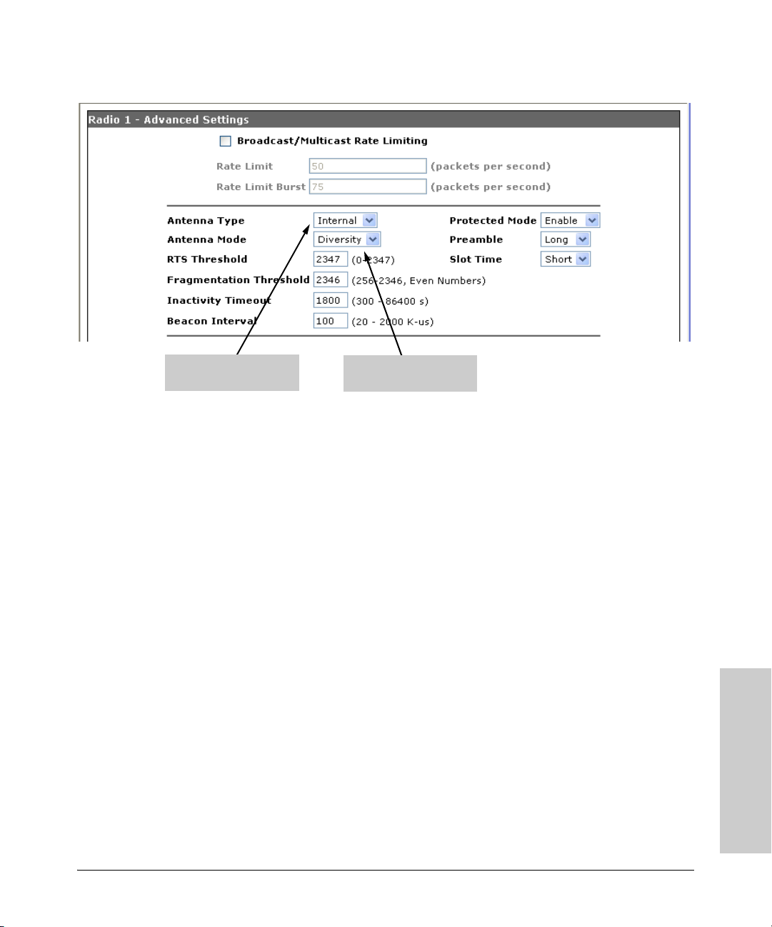
Using an External Antenna with the Access Point 530
Installation Procedures
Antenna Type selection;
Internal or External.
Antenna Mode selection;
Diversity or Single.
with the Access Point 530
Using an External Antenna
4-7
Page 62

— This page is intentionally unused. —
Page 63

5
Troubleshooting
This chapter describes how to troubleshoot your ProCurve Wireless
Access Point 530. Note that this document describes troubleshooting mostly
from a hardware perspective. You can perform more in-depth troubleshooting
on the Access Point 530 using the software tools available with the access
point, including the full-featured console interface and the built-in Web
browser interface.
This chapter describes the following:
■ basic troubleshooting tips (page 5-1)
■ diagnosing with the LEDs (page 5-3)
■ proactive networking tools (page 5-5)
■ hardware diagnostic tests (page 5-6)
■ restoring customer and factory default configurations (page 5-8)
■ downloading new software to the Access Point 530 (page 5-10)
■ HP Customer Support Services (page 5-10)
Troubleshooting
Basic Troubleshooting Tips
Most problems are caused by the following situations. Check for these items
first when starting your troubleshooting:
■ Connecting to devices that have a fixed full-duplex configuration.
By default, the RJ-45 port uses auto-negotiation to determine the duplex
mode. That is, when connecting to attached devices, the access point will
operate in one of two ways to determine the link speed and the communication mode (half duplex or full duplex):
• If the connected device is also configured to use auto-negotiation, the
access point will automatically negotiate both link speed and communication mode.
• If the connected device has a fixed configuration, for example
100 Mbps, at half or full duplex, the access point will automatically
sense the link speed, but will default to a communication mode of half
duplex.
5-1
Page 64

Troubleshooting
Basic Troubleshooting Tips
Because the Access Point 530 behaves in this way (in compliance with
the IEEE 802.3-2005 standard), if a device connected to the access point
has a fixed configuration at full duplex, the device will not connect
correctly to the access point. The result will be high error rates and very
inefficient communications between the access point and the device.
All devices connected to the Access Point 530 should be configured to
auto-negotiate. To correct this problem you have to manually set the
Troubleshooting
access point’s RJ-45 port to match the duplex mode used by the attached
device.
■ Faulty or loose cables. Look for loose or obviously faulty connections.
If the cables appear to be OK, make sure the connections are secure. If
that does not correct the problem, try a different cable.
■ Non-standard cables. Non-standard and miswired cables may cause
network collisions and other network problems, and can seriously impair
network performance. Use a new correctly-wired cable or compare your
cable to the cable in appendix B, “Access Point Port and Network Cables”
for pinouts and correct cable wiring. A category 5 cable tester is a
recommended tool for every 100Base-TX network installation.
■ Improper Network Topologies. It is important to make sure you have
a valid network topology. Common topology faults include excessive
cable length and excessive repeater delays between end nodes. If you have
network problems after recent changes to the network, change back to
the previous topology. If you no longer experience the problems, the new
topology is probably at fault. Sample topologies are shown at the end of
chapter 2 in this book, and some topology configuration guidelines can
be found online at the ProCurve Networking Web site, http://
www.hp.com/rnd/index.htm. under “network configuration examples.”
■ Mobile users cannot connect to the network. Make sure that the
access point and wireless stations are configured with compatible security settings. Check to ensure that the wireless station is within the
maximum range supported by the access point. Also verify that the
wireless station has been configured with an IP address compatible with
the attached network, either manually or via DHCP.
5-2
For more information on possible network problems and their solutions, refer
to the technical note “Troubleshooting LAN Performance and Intermittent
Connectivity Problems”, which can be found on the ProCurve Networking
Web site , http://www.hp.com/go/hpprocurve, in the Reference Library section
under http://www.hp.com/rnd/library/index.htm under “T” in the “A-Z
index.”
Page 65

Diagnosing with the LEDs
Troubleshooting
Diagnosing with the LEDs
Table 5-1 shows LED patterns on the access point that indicate problem
conditions.
1. Check in the table for the LED pattern that you see on your access point.
2. Refer to the corresponding diagnostic tip on the next few pages.
Table 5-1. LED Error Indicators
LED Pattern Indicating Problems
Power LED Radio LEDs LAN LED
Off with power cord plugged in * * 1
Off without po wer cord plugged in,
but linked to a PoE source
Prolonged on or off during
initialization
†
On Off * 4
On * Off with cable
On * On, but the port is not
Prolonged on or off
during initialization
**2
Prolonged on or off
†
during initialization
connected
communicating
Diagnostic
†
Tips
3
5
6
Troubleshooting
* This LED is not important for the diagnosis.
†
Initialization takes between 30 seconds and one minute after a power on or reset.
Diagnostic Tips:
Tip Problem Solution
1 The access point
is not plugged
into an active AC
power source, or
the access
point’s AC power
adapter may
have failed.
1. Verify that the power cord is plugged into an active power source and to the access
point's AC power adapter. Make sure these connections are secure.
2. Try power-cycling the access point by unplugging and plugging the power cord back
in.
3. If the Power LED is still not on, verify that the AC power source works by plugging
another device into the outlet. Or try plugging the access point into a different outlet
or try a different power cord.
If the power source and power cord are OK and this cond ition persists, the access point’s
AC power adapter may have failed. Call your HP-authorized network reseller, or use the
electronic support services from HP to get assistance. See the Customer Support/
Warranty booklet for more information.
5-3
Page 66

Troubleshooting
Diagnosing with the LEDs
Tip Problem Solution
2 The access point
is not receiving
power from the
PoE source.
3 The access point
Troubleshooting
has experienced
a software
failure during
initialization.
4 Wireless link has
been
administratively
disabled.
1. Verify that access point’s 10/100Base-TX port is attached to a PoE source device.
2. Verify that the PoE source device is powered on, and that the PoE function has been
administratively enabled on the source port attached to the access point.
3. Refer to Tip 6 to verify that the network cable is functioning properly.
After a power on or reset, the LEDs indicate stages of the system initialization. If there is
a software failure during initialization, the LED pattern indicates at which stage the failure
occurred. The normal LED sequence during initialization is as follows:
Stage 1. Power LED on for 5 seconds. System initialization has started.
Stage 2. LAN LED blinks 5 times in 1 second. The boot ROM has successfully initialized.
Stage 3. All LEDs on for 5 seconds. The operating system kernel has successfully loaded.
Stage 4. LAN LED on only. The operating system is mounting the file system.
Stage 5. LAN and 11a/b/g LEDs on. Radio drivers have been successfully loaded.
Stage 6. LAN, 11a/b/g, and 11b/g LEDs on. The access point software is initializing.
Stage 7. Normal LED operation. Initialization has completed successfully.
The entire initialization sequence takes between 30 seconds (normal reset) and one
minute (factory default reset). If one of the above LED patterns display longer than one
minute, a failure has occurred. Do the following:
1. Reset the access point by pressing the Reset button on the back of the access point,
or by power cycling the access point.
2. If the fault indication reoccurs, attach a console to the access point (as indicated in
chapter 2). Then, reset the access point. Messages should appear on the console
screen identifying the error condition. Take note of the LED pattern and contact your
HP-authorized network reseller, or use the electronic support services from HP to get
assistance. See the Customer Support/Warranty booklet for more information.
Verify that the wireless port has not been disabled through an access point configuration
change. You can use the console interface, or, if you have configured an IP address on
the access point, use the Web browser interface to determine the state of the wireless
port and re-enable the port if necessary. Also verify that the country code has been set.
5 The
10/100Base-TX
network
connection is not
working
properly.
6 The port may be
improperly
configured.
5-4
Try the following procedures:
• Verify that both ends of the cabling, at the access point and the connected device, are
connected properly.
• Verify the connected device and access point are both powered on and operating
correctly.
• Verify duplex operation (see page 5-1).
• If these procedures don’t resolve the problem, try using a different cable.
VLAN configuration may affect the port operation. Use the access point’s console to see
how the port is configured for VLANs.
Make sure also, that the device at the other end of the connection is indicating a good
link to the access point. If it is not, the problem may be with the cabling between the
devices or the connectors on the cable.
Page 67

Troubleshooting
Proactive Networking
Proactive Networking
The following interfaces provide tests, indicators, and an event log that can
be used to monitor the access point and its network connections and to help
you troubleshoot:
■ A graphical Web browser interface that you can use to manage your access
point from a PC running a supported Web browser, for example Microsoft
Internet Explorer.
The Device Information tab can be used to display access point configuration settings, attached wireless station settings, and the event log.
■ A full-featured easy-to-use console interface that you can access by
connecting a standard terminal or PC running a terminal emulator to the
access point’s console port. (For information on the console port’s pin
assignments, see “Direct Console Access” on page 2-15.) The console
interface is also accessible through a Telnet or Secure Shell connection.
The ping command can test device access and connectivity. The show
command at all levels of the CLI provides detailed access point configuration information.
Troubleshooting
5-5
Page 68

Troubleshooting
Hardware Diagnostic Tests
Hardware Diagnostic Tests
Testing the Access Point by Resetting It
If you believe that the access point is not operating correctly, you can reset
Troubleshooting
Caution If you press the Reset button with the Clear button in a specific pattern, you
the access point. To reset the access point, either
■ Unplug and plug in the power cord (power-cycling).
■ Press the Reset button on the back of the access point for about two
seconds (until the LEDs start to blink rapidly). If you are attached to the
console port, you will see that the access point starts its system initialization.
reset the board and reload the factory default settings. See “Restoring Custom
and Factory Default Configurations” on page 5-8.
Power-cycling the access point and pressing the Reset button both cause the
access point to perform its system initialization, which normally resolves any
temporary operational problems. These reset processes also cause any
network traffic counters to be reset to zero, and cause the System Up Time
timer to reset to zero. Also, event log messages are erased, and the IP address
may be changed if you are using DHCP.
5-6
Checking the Access Point’s LEDs
The system initialization is successful when the Power LED is on and the other
LEDs are in a normal operating state after approximately one minute. If the
LED pattern is different that this for longer than one minute, there may be a
problem with the access point.
See “Diagnosing with the LEDs” on page 5-3 for information on interpreting
the LED patterns.
Checking Event Messages
Useful diagnostic messages may be displayed on the console screen when the
access point is reset. As described in chapter 2 under step 7, “Connect a
console to the access point,” connect a PC running a VT-100 terminal emulator
program or a standard VT-100 terminal to the access point’s Console Port and
configure it with the terminal communication settings shown on page 2-14.
Page 69

Hardware Diagnostic Tests
Troubleshooting
Then, when you reset the access point, note the messages that are displayed.
Additionally, you can check the access point’s event log, which can be
accessed from the Web browser or a Syslog server.
Testing Twisted-Pair Cabling
Network cables that fail to provide a link or provide an unreliable link between
the access point and the connected network device may not be compatible
with the IEEE 802.3 Type 10Base-T, or 100Base-TX standards. The twisted-pair
cables attached to the Access Point 530 must be compatible with the appropriate standards. To verify that your cable is compatible with these standards,
use a qualified cable test device.
Testing Access Point-to-Device Network Communications
You can perform the following communication tests to verify that the network
is operating correctly between the access point and any connected device that
can respond correctly to the communication test.
■ Ping Test -- a network layer test used on IP networks that sends test
packets to any device identified by its IP address
Troubleshooting
These tests can be performed through the access point’s console interface
from a terminal connected to the access point or through a Telnet or Secure
Shell connection. For more information, see the Management and Configu-
ration Guide, which is on the Documentation CD-ROM that came with your
access point.
Testing End-to-End Network Communications
Both the access point and the cabling can be tested by running an end-to-end
communications test -- a test that sends known data from one network device
to another through the access point. You can run a Ping test to verify that the
entire communication path between the two network devices is functioning
correctly.
5-7
Page 70

Troubleshooting
Restoring Custom and Factory Default Configurations
Restoring Custom and Factory Default
Configurations
As part of your troubleshooting process on the Access Point 530, it may
Troubleshooting
Note Restoring factory defaults removes all access point configuration changes that
become necessary to return the access point’s configuration to custom or
factory default settings. This process momentarily interrupts the access
point’s operation, clears the console event log, resets the network counters to
zero, and reboots the access point. If restoring a custom default configuration,
some basic settings, such as a Manager password and IP address, may be
retained. When restoring the factory default configuration, all settings are
cleared, including the Manager password and any IP address.
you have made from the factory default settings. This includes, for example,
IP addresses, and radio interface settings. Returning the configuration of these
features to their factory default settings may result in network connectivity
issues.
If the access point has a valid configuration, and you are restoring the factory
default settings for a reason other than configuration problems, you should
save the access point configuration prior to performing the factory default
reset. Then, after the reset and resolution of the original problem, you can
restore the saved configuration to the access point. For both the save and
restore processes, you can use the console copy command. For more information on this command, see the Management and Configuration Guide, which
is on the Documentation CD-ROM that came with your access point.
You can restore a custom or factory default configuration either from the
access point itself, or through the access point console.
Note The system, password, custom default, and factory default reset functions can
be disabled by the access point’s software. For more information, see the
Management and Configuration Guide, which is on the Documentation
CD-ROM that came with your access point.
To reset the access point configuration back to custom defaults, perform these
steps:
1. Press the reset and clear buttons simultaneously.
5-8
Page 71

Restoring Custom and Factory Default Configurations
Troubleshooting
2. Once the LEDs shut off, release the reset button. The LEDs flash rapidly
about once per second.
3. While the LEDs are still flashing, release the clear button. The configuration sets to the custom default settings and the AP is rebooted.
To restore a custom default configuration using the console, execute the erase
startup-config command from the console command prompt.
To execute the factory default reset on the access point, perform these steps:
1. Press the reset and clear buttons simultaneously.
2. Once the LEDs shut off, release the reset button. The LEDs will then flash
about once per second.
3. Press the reset button (while continuing to hold the clear button). After
about one second, all LEDs will flash rapidly (about 10 times per second).
4. After the LEDs begin to flash rapidly, release the clear button. The AP
resets to factory defaults and reboots. You can then release the reset
button.
To restore the factory default configuration using the console, execute the
copy factory-default startup-config command from the console command
prompt.
Troubleshooting
5-9
Page 72

Troubleshooting
Downloading New Access Point Software
Downloading New Access Point
Software
When product enhancements occur for the Access Point 530, new software
can be downloaded to the access point by several methods. For more information, see the Management and Configuration Guide, which is on the
Troubleshooting
Documentation CD-ROM that came with your access point.
The new access point software is made available on the ProCurve Networking
Web site, http://www.hp.com/go/hpprocurve under “product support – software upgrades.”
HP Customer Support Services
If you are still having trouble with your access point, Hewlett-Packard offers
support 24 hours a day, seven days a week through the use of a number of
automated electronic services. See the Customer Support/Warranty booklet
that came with your access point for information on how to use these services
to get technical support. The ProCurve Networking Web site, http://
www.hp.com/go/hpprocurve also provides up-to-date support information
under “product support.”
5-10
Additionally, your HP-authorized network reseller can provide you with assistance, both with services that they offer and with services offered by HP.
Before Calling Support
To make the support process most efficient, before calling your networking
dealer or HP Support, you first should retrieve the following information:
Information Item Information Location
• product identification the front of the access point,
Access Point 530 (J8986A or J8987A)
• details about the access point’s status
including the software (OS) version, a
copy of the access point co nfiguration,
a copy of the access point Event Log,
and a copy of the access point status
and counters information
• access point console (Global Configura-
tion Level): show command
• access point Web interface: Event Log
• Syslog server entry file, if configured
Page 73

HP Customer Support Services
Information Item Information Location
Troubleshooting
• copy of your network topology map, in-
cluding network addresses assigned to
the relevant devices
your network records
Troubleshooting
5-11
Page 74

— This page is intentionally unused. —
Page 75

Specifications
Physical
Width: 24.9 cm (9.8 in.)
Depth: 17.3 cm (6.8 in.)
Height: 2.3 cm (0.9 in.)
Weight: 0.73 kg (1.6 lb)
A
Specifications
Electrical
Adapter
AC voltage: 100-240 volts, 0.4A, 50/60 Hz
DC voltage: 48 volts, 0.26A (max)
Power consumption: 12.5 watts (max)
Note: Power can also be provided to the access point through the Ethernet
port based on IEEE 802.3af Power over Ethernet (PoE) specifications. The
access point is a Class 3 device, that is, the maximum power required is in the
range of 6.49 to 12.95 watts. When both PoE is provided and the adapter is
plugged in, PoE is turned off.
Environmental
Operating Non-Operating
Temperature: 0° C to 50° C (32° F to 122° F) PoE mode
0° C to 40° C (32° F to 104° F) w/adapter
Relative humidity:
(non-condensing)
Maximum altitude: 3.05 Km (10,000 ft) 4.6 Km (15,000 ft)
5% to 95% 5% to 95%
-40° C to 70° C (-40° F to 158° F)
A-1
Page 76

Specifications
Connectors
■ The 10/100 Mbps RJ-45 twisted-pair port is compatible with the
IEEE 802.3u 100Base-TX and IEEE 802.3 Type 10Base-T standards.
Note: To provide Power over Ethernet to the access point, all 4 pairs of
wires must be connected for any network cable attached to this port.
Safety
Complies with:
■ IEC 60950-1: 2001
■ EN 60950-1: 2002
■ UL 60950-1 1st Ed.
■ UL 2043
■ CAN/CSA-C22.2 No. 60950-1-03
Specifications
EMC Compliance (Class B)
Complies with:
■ FCC Part 15.107 and 15.109
■ ICES-003 (Canada)
■ VCCI
Radio Signal Certification
Complies with:
■ FCC Part 15, Subpart C and E
■ RSS-210 (Canada), Issue 6 (September 2005)
■ EN 300.328 V1.6.1 (2004-07)
■ EN 301.893 V1.2.3 (2003-08)
■ ARIB RCR STD-T66 (Ch 1~13), STD-33 (Ch 14), STD-71 (802.11a)
■ DGT LP0002 (Taiwan)
Immunity
■ EN 301.489-1 V1.5.1 (2004-07)
■ EN 301.489-17 V1.2.1 (2002-08)
■ EN 60601-1-2
A-2
Page 77

Specifications
Wireless
802.11b/g
Radio Standard: IEEE 802.11b/g
Radio Technology: Direct Sequence Spread Spectrum (DSSS)
Orthogonal Frequency Division Multiplexing (OFDM)
Data Rate: 1, 2, 5.5, 6, 9, 11, 12, 18, 24, 36, 48, 54 Mbps per channel
Operating Frequency: 2.4 ~ 2.4835 GHz (US, Canada, ETSI)
2.4 ~ 2.497 GHz (Japan)
Maximum Channels: FCC/IC: 1-11, ETSI: 1-13, MKK: 1-13 (802.11g), 1-14 (802.11b)
Modulation Type: BPSK, QPSK, 16QAM, 64QAM / OFDM, BPSK, QPSK, CCK / DSSS
Media Access Protocol: CSMA/CA with ACK
Transmit Output Power: 22 dBm (max)
802.11a
Radio Standard: IEEE 802.11a
Radio Technology: Orthogonal Frequency Division Multiplexing (OFDM)
Data Rate: 6, 9, 12, 18, 24, 36, 48, 54 Mbps per channel
Operating Frequency: 5.15 ~ 5.25 GHz (lower band) US, Canada, Japan, ETSI
5.25 ~ 5.35 GHz (middle band) US, Canada, ETSI
5.725 ~ 5.825 GHz (upper band) US, Canada
5.50 ~ 5.70 GHz ETSI
Maximum Channels: FCC/IC: 12, ETSI: 19, MKK: 8
Modulation Type: BPSK, QPSK, 16QAM, 64QAM
Media Access Protocol: CSMA/CA with ACK
Transmit Output Power: 18 dBm (max)
Specifications
A-3
Page 78

Specifications
Receiver Sensitivity
Radio ProCurve AP530 NA (J8986A) ProCurve AP530 WW (J8987A)
802.11b
(typical)
802.11g
(typical)
802.11a
(typical)
11Mbps @ -87dBm; 5.5Mbps @ -91dBm;
2Mbps @ -92dBm; 1Mbps @ -97dBm
54Mbps @ -74dBm; 48Mbps @ -75dBm;
36Mbps @-80dBm; 24Mbps @ -83dBm;
18Mbps @-86dBm; 12Mbps @ -88dBm;
9Mbps @ -90dBm; 6Mbps @ -91dBm
54Mbps @ -70dBm; 48Mbps @ -72dBm;
36Mbps @-78dBm; 24Mbps @ -81dBm;
18Mbps @-85dBm; 12Mbps @ -87dBm;
9Mbps @ -89dBm; 6Mbps @ -90dBm
11Mbps @ -87dBm; 5.5Mbps @ -89dBm;
2Mbps @ -91dBm; 1Mbps @ -94dBm
54Mbps @ -75dBm; 48Mbps @ -77dBm;
36Mbps @ -81dBm; 24Mbps @ -84dBm;
18Mbps @-87dBm; 12Mbps @ -88dBm;
9Mbps @ -89dBm; 6Mbps @ -90dBm
54Mbps @ -70dBm; 48Mbps @ -72dBm;
36Mbps @-78dBm; 24Mbps @ -81dBm;
18Mbps @-84dBm; 12Mbps @ -87dBm;
9Mbps @ -88dBm; 6Mbps @ -89dBm
Specifications
A-4
Page 79

Access Point Port and Network Cables
This appendix includes access point connector information and network
cable information for cables that should be used with the Access Point 530,
including minimum pin-out information and specifications for twisted-pair
cables.
Note Incorrectly wired cabling is the most common cause of problems for LAN
communications. HP recommends that you work with a qualified LAN cable
installer for assistance with your cabling requirements.
Access Point Ports
The fixed RJ-45 10/100Base-TX port on the access point accepts 100-ohm
unshielded twisted-pair cable with RJ-45 connectors as described on the next
page.
B
Twisted-Pair Cables
10 Mbps Operation Category 3, 4, or 5 100-ohm unshielded twisted-pair (UTP),
complying with IEEE 802.3 Type 10Base-T specifications,
fitted with RJ-45 connectors
100 Mbps Operation Category 5 100-ohm UTP cable, complying with IEEE
802.3u 100Base-TX specifications, fitted with RJ-45 connectors
Access Point Port and
Network Cables
B-1
Page 80

Access Point Port and Network Cables
Twisted-Pair Cable/Connector Pin-Outs
Twisted-Pair Cable/Connector Pin-Outs
The access point includes one 10/100Base-TX port. This port uses the “HP Auto
MDIX” feature, which means that you can use either straight-through or
crossover twisted-pair cables to connect the access point to a switch.
Other Wiring Rules:
■ All twisted-pair wires used for 10 Mbps, and 100 Mbps operation must be
twisted through the entire length of the cable. The wiring sequence must
conform to EIA/TIA 568-B (not USOC). See “Twisted-Pair Cable Pin
Assignments” later in this appendix for a listing of the signals used on each
pin.
■ For 10 Mbps connections to the ports, you can use Category 3, 4, or 5
unshielded twisted-pair cable, as supported by the IEEE 802.3 Type
10Base-T standard.
■ For 100 Mbps connections to the ports, use 100-ohm Category 5 UTP cable
only, as supported by the IEEE 802.3u Type 100Base-TX standard.
■ To provide Power over Ethernet to the access point, all 4 pairs must be
connected for any network cable attached to this port; the cable must
meet ISO/DIS 11801 Class D requirements and IEEE 802.3af requirements.
Access Point Port and
Network Cables
B-2
Page 81

Access Point Port and Network Cables
Twisted-Pair Cable/Connector Pin-Outs
Straight-Through Twisted-Pair Cable for 10 Mbps or 100 Mbps Network Connections
Because the 10/100 port on the access point supports auto-MDIX operation,
you can use either “straight-through” or “crossover” cable for network connections to PCs, servers, hubs, or switches.
Cable Diagram
Note Pins 1 and 2 on connector “A” must be wired as a twisted pair to pins 1 and 2
on connector “B”.
Pins 3 and 6 on connector “A” must be wired as a twisted pair to pins 3 and 6
on connector “B”.
Pins 4, 5, 7, and 8 are not used for transmitting or receiving data, although they
must be wired straight-through in the cable to support Power over Ethernet.
.
Pin Assignments
Access Point End (MDI) Hub or Switch Port, or Other
Signal Pins Pins Signal
receive +
receive transmit +
transmit -
1
2
3
6
MDI-X Port End
1
2
3
6
transmit +
transmit receive +
receive -
B-3
Access Point Port and
Network Cables
Page 82

Access Point Port and Network Cables
Twisted-Pair Cable/Connector Pin-Outs
Crossover Twisted-Pair Cable for 10 Mbps or 100 Mbps Network Connection
Because the 10/100 port on the access point supports auto-MDIX operation,
you can use either “straight-through” or “crossover” cable for network connections to PCs, servers, hubs, or switches.
Cable Diagram
Access Point Port and
Note Pins 1 and 2 on connector “A” must be wired as a twisted pair to pins 3 and 6
on connector “B”.
Pins 3 and 6 on connector “A” must be wired as a twisted pair to pins 1 and 2
on connector “B”.
Pins 4, 5, 7, and 8 are not used for transmitting or receiving data, although they
must be wired straight-through in the cable to support Power over Ethernet.
.
Network Cables
B-4
Pin Assignments
Access Point End (MDI) Computer, Transceiver, or
Signal Pins Pins Signal
receive +
receive transmit +
transmit -
1
2
3
6
Other MDI Port End
6
3
2
1
transmit transmit +
receive receive +
Page 83

Safety and EMC Regulatory Statements
Safety Information
Documentation r eference symbol. If the product is marked with this
!
symbol, refer to the product documentation to get more information
about the product.
C
WARNING A WARNING in the manual denotes a hazard that can cause injury
or death.
CAUTION A CAUTION in the manual denotes a hazard that can damage the
equipment or create a non-compliant condition.
Do not proceed beyond a WARNING or CAUTION notice until you
have understood the hazardous conditions and have taken appropriate steps.
Grounding
This product is a safety class I compliant product and has a protective earthing
terminal. There must be an uninterruptible safety earth ground from the main
power source to the product's power cord or supplied power cord set.
Whenever it is likely that the protection has been impaired, disconnect the
power cord until the ground has been restored.
For LAN cable grounding:
■ If your LAN covers an area served by more than one power distribu-
tion system, be sure their safety grounds are securely interconnected.
■ LAN cables may occasionally be subject to hazardous transient volt-
ages (such as lightning or disturbances in the electrical utilities power
grid). Handle exposed metal components of the network with caution.
Servicing
There are no user-serviceable parts inside this product. Any servicing, adjustment, maintenance, or repair must be performed only by service-trained
personnel.
Safety and EMC Regulatory
Statements
This product does not have a power switch; it is powered on when the power
cord is plugged in.
C-1
Page 84

Safety and EMC Regulatory Statements
Safety Information
Regulatory Model Identification Number
For regulatory identification purposes, this product has been assigned a
Regulatory Model Number (RMN). The RMN for your product is RSVLC-
0501. The RMN should not be confused with the marketing name (Wireless
Enterprise Access Point 530) or the Product Number (J8986A, J8987A).
Statements
Safety and EMC Regulatory
C-2
Page 85

Safety and EMC Regulatory Statements
Informations concernant la sécurité
Informations concernant la sécurité
Symbole de référence à la documentation. Si le produit est marqué de
!
ce symbole, report ez-vous à la documentation du p roduit afin d'obtenir
des informations plus détaillées.
WARNING Dans la documentation, un WARNING indique un danger susceptible
CAUTION Un texte de mise en garde intitulé CAUTION indique un danger suscep-
Cet appareil est un produit de classe I et possède une borne de mise à la terre. La source
d'alimentation principale doit être munie d'une prise de terre de sécurité installée aux
bornes du câblage d'entrée, sur le cordon d'alimentation ou le cordon de raccordement
fourni avec le produit. Lorsque cette protection semble avoir été endommagée,
débrancher le cordon d'alimentation jusqu'à ce que la mise à la terre ait été réparée.
Mise à la terre du câble de réseau local:
■ si votre réseau local s'étend sur une zone desservie par plus d'un système de
distribution de puissance, assurez-vous que les prises de terre de sécurité
soient convenablement interconnectées.
■ Les câbles de réseaux locaux peuvent occasionnellement être soumis à des
surtensions transitoires dangereuses (telles que la foudre ou des perturbations dans le réseau d'alimentation public). Manipulez les composants
métalliques du réseau avec précautions.
Aucune pièce contenue à l'intérieur de ce produit ne peut être réparée par l'utilisateur.
Tout dépannage, réglage, entretien ou réparation devra être confié exclusivement à un
personnel qualifié.
d'entraîner des dommages corporels ou la mort.
tible de causer des dommages à l'équipement.
Ne continuez pas au-delà d'une rubrique WARNING ou CAUTION avant
d'avoir bien compris les conditions présentant un danger et pris les
mesures appropriées.
Cet appareil ne comporte pas de commutateur principal ; la mise sous tension est
effectuée par branchement du cordon d'alimentation.
Safety and EMC Regulatory
Statements
C-3
Page 86

Safety and EMC Regulatory Statements
Hinweise zur Sicherheit
Hinweise zur Sicherheit
!
Symbol für Dokumentationsverweis. Wenn das Produkt mit diesem
Symbol markiert ist, schlagen Sie bitte in der Produktdokumentation
nach, um mehr Informationen über das Produkt zu erhalten.
WARNING Eine WARNING in der Dokumentation symbolisiert eine Gefahr, die
CAUTION CAUTION in der Dokumentation symbolisiert eine Gefahr, die dis
Dies ist ein Gerät der Sicherheitsklasse I und verfügt über einen schützenden Erdungsterminal. Der Betrieb des Geräts erfordert eine ununterbrochene Sicherheitserdung
von der Hauptstromquelle zu den Geräteingabeterminals, den Netzkabeln oder dem
mit Strom belieferten Netzkabelsatz voraus. Sobald Grund zur Annahme besteht, daß
der Schutz beeinträchtigt worden ist, das Netzkabel aus der Wandsteckdose herausziehen, bis die Erdung wiederhergestellt ist.
Für LAN-Kabelerdung:
■ Wenn Ihr LAN ein Gebiet umfaßt, das von mehr als einem Stromverteilungs-
system beliefert wird, müssen Sie sich vergewissern, daß die
Sicherheitserdungen fest untereinander verbunden sind.
■ LAN-Kabel können gelegentlich gefährlichen Übergangsspannungen aus-
gesetzt werden (beispielsweise durch Blitz oder Störungen in dem
Starkstromnetz des Elektrizitätswerks). Bei der Handhabung exponierter
Metallbestandteile des Netzwerkes Vorsicht walten lassen.
Dieses Gerät enthält innen keine durch den Benutzer zu wartenden Teile. Wartungs-,
Anpassungs-, Instandhaltungs- oder Reparaturarbeiten dürfen nur von geschultem
Bedienungspersonal durchgeführt werden.
Verletzungen oder sogar Todesfälle verursachen kann.
Gerät beschädigen kann.
Fahren Sie nach dem Hinweis WARNING oder CAUTION erst fort,
nachdem Sie den Gefahrenzustand verstanden und die entsprechenden Maßnahmen ergriffen haben.
Dieses Gerät hat keinen Netzschalter; es wird beim Anschließen des Netzkabels
eingeschaltet.
Statements
Safety and EMC Regulatory
C-4
Page 87

Safety and EMC Regulatory Statements
Considerazioni sulla sicurezza
Considerazioni sulla sicurezza
Simbolo di riferimento alla documentazione. Se il prodotto è contras-
!
segnato da questo simbolo, fare riferimento alla documentazione sul
prodotto per ulteriori informazioni su di esso.
WARNING La dicitura WARNING denota un pericolo che può causare lesioni o
morte.
CAUTION La dicitura CAUTION denota un pericolo che può danneggiare le
attrezzature.
Non procedere oltre un avviso di WARNING o di CAUTION prima di
aver compreso le condizioni di rischio e aver provveduto alle misure
del caso.
Questo prodotto è omologato nella classe di sicurezza I ed ha un terminale protettivo
di collegamento a terra. Dev'essere installato un collegamento a terra di sicurezza, non
interrompibile che vada dalla fonte d'alimentazione principale ai terminali d'entrata,
al cavo d'alimentazione oppure al set cavo d'alimentazione fornito con il prodotto.
Ogniqualvolta vi sia probabilità di danneggiamento della protezione, disinserite il cavo
d'alimentazione fino a quando il collegaento a terra non sia stato ripristinato.
Per la messa a terra dei cavi LAN:
■ se la vostra LAN copre un'area servita da più di un sistema di distribuzione
elettrica, accertatevi che i collegamenti a terra di sicurezza siano ben collegati
fra loro;
■ i cavi LAN possono occasionalmente andare soggetti a pericolose tensioni
transitorie (ad esempio, provocate da lampi o disturbi nella griglia d'alimentazione della società elettrica); siate cauti nel toccare parti esposte in metallo
della rete.
Nessun componente di questo prodotto può essere riparato dall'utente. Qualsiasi
lavoro di riparazione, messa a punto, manutenzione o assistenza va effettuato esclusivamente da personale specializzato.
Questo apparato non possiede un commutatore principale; si mette scotto tensione
all'inserirsi il cavo d'alimentazione.
Safety and EMC Regulatory
C-5
Statements
Page 88

Safety and EMC Regulatory Statements
Consideraciones sobre seguridad
Consideraciones sobre seguridad
Símbolo de referencia a la documentación. Si el producto va
!
marcado con este símbolo, consultar la documentación del
producto a fin de obtener mayor información sobre el producto.
WARNING Una WARNING en la documentación señala un riesgo que podría
CAUTION Una CAUTION en la documentación señala un riesgo que podría
Este aparato se enmarca dentro de la clase I de seguridad y se encuentra protegido por
una borna de puesta a tierra. Es preciso que exista una puesta a tierra continua desde
la toma de alimentación eléctrica hasta las bornas de los cables de entrada del aparato,
el cable de alimentación o el juego de cable de alimentación suministrado. Si existe la
probabilidad de que la protección a tierra haya sufrido desperfectos, desenchufar el
cable de alimentación hasta haberse subsanado el problema.
Puesta a tierra del cable de la red local (LAN):
■ Si la LAN abarca un área cuyo suministro eléctrico proviene de más de una
red de distribución de electricidad, cerciorarse de que las puestas a tierra
estén conectadas entre sí de modo seguro.
■ Es posible que los cables de la LAN se vean sometidos de vez en cuando a
voltajes momentáneos que entrañen peligro (rayos o alteraciones en la red
de energía eléctrica). Manejar con precaución los componentes de metal de
la LAN que estén al descubierto.
Este aparato no contiene pieza alguna susceptible de reparación por parte del usuario.
Todas las reparaciones, ajustes o servicio de mantenimiento debe realizarlos solamente el técnico.
resultar en lesiones o la muerte.
resultar en averías al equipo.
No proseguir d espués de un símbolo de WARNING o CAUTION hast a
no haber entendido las condiciones peligrosas y haber tomado las
medidas apropiadas.
Este producto no tiene interruptor de potencia; se activa cuando se enchufa el cable
de alimentación.
Statements
Safety and EMC Regulatory
C-6
Page 89

Safety and EMC Regulatory Statements
Safety Information (Japan)
Safety Information (Japan)
C-7
Safety and EMC Regulatory
Statements
Page 90

Safety and EMC Regulatory Statements
Safety Information (China)
Safety Information (China)
Statements
Safety and EMC Regulatory
C-8
Page 91

Safety and EMC Regulatory Statements
EMC Regulatory Statements
EMC Regulatory Statements
Notice for U.S.A.
Manufacturer’s FCC Declaration of Conformity Statement
Tested to Comply
with FCC Standards
Product No: J8986A
Regulatory Model No: RSVLC-0501
Manufacturer: Hewlett-Packard Company
3000 Hanover Street
Palo Alto, CA 94304-1185 USA
Phone: 650-857-1501
For questions regarding this declaration, contact the Product Regulations
Manager at the above address or phone number.
This device complies with Part 15 of the FCC rules. Operation is subject to the
following two conditions: 1) this device may not cause harmful interference,
and 2) this device must accept any interference received, including interference that may cause undesired operation.
This equipment has been tested and found to comply with the limits for a Class
B digital device, pursuant to Part 15 of the FCC Rules. These limits are
designed to provide reasonable protection against harmful interference in a
residential installation. This equipment generates, uses and can radiate radio
frequency energy and, if not installed and used in accordance with instructions, may cause harmful interference to radio communications. However,
there is no guarantee that the interference will not occur in a particular
installation. If this equipment does cause harmful interference to radio or
television reception, which can be determined by turning the equipment off
and on, the user is encouraged to try to correct the interference by one or more
of the following measures:
■ Reorient the receiving antenna
■ Increase the separation between the equipment and receiver
■ Connect the equipment into an outlet on a circuit different from that to
which the receiver is connected
■ Consult the dealer or an experienced radio/TV technician for help
Safety and EMC Regulatory
Statements
C-9
Page 92

Safety and EMC Regulatory Statements
EMC Regulatory Statements
The FCC requires the user to be notified that any changes or modifications
made to the device that are not expressly approved by the Hewlett-Packard
Company may void the user’s authority to operate the equipment.
If this device is going to be operated in the 5.15 ~ 5.25 GHz frequency range,
then it is restricted to an indoor environment only.
!
Notice for Canada
This device complies with the limits for a Class B digital device and conforms
to Industry Canada standard ICES-003. Products that contain a radio transmitter comply with Industry Canada standard RSS210 and are labeled with an
IC approval number.
Warning: Exposure to Radio Frequency Radiation
The radiated output power of this device is below the FCC radio
exposure limits. Nevertheless, the device should be used in such
a manner that the potential for human contact during normal
operation is minimized. To avoid the possibility of exceeding the
FCC radio frequency exposure limits, human proximity to the
antennas should not be less than 25 cm (10 inches) during normal
operation.
Cet appareil numérique de la classe B est conforme à la norme ICES-003 de
Industry Canada. La radio sans fil de ce dispsitif est conforme à la certification
RSS 210 de Industry Canada et est étiquetée avec un numéro d’approbation IC.
This device complies with the Class B limits of Industry Canada. Operation is
subject to the following two conditions: 1) this device may not cause harmful
interference, and 2) this device must accept interference received, including
interference that may cause undesired operation.
This device has been designed to operate with the antennas listed in this
section, having a maximum gain of 13.8 dBi. Antennas not included in this list
or having a gain greater that 13.8 dBi are strictly prohibited for use with this
device. The required impedance is 50 ohms.
To reduce potential radio interference with other users, the antenna type and
its gain should be so chosen that the equivalent isotropically radiated power
(EIRP) is not more than that required for successful communication.
Statements
Safety and EMC Regulatory
C-10
If this device is going to be operated in the 5.15 ~ 5.25 GHz frequency range,
then it is restricted to an indoor environment only.
Page 93

Safety and EMC Regulatory Statements
EMC Regulatory Statements
Notice for European Community
This device complies with the EMC Directive 89/336/EEC, Low Voltage Directive 73/23/EEC and R&TTE Directive 1999/5/EC. Compliance with these directives implies conformity to harmonized European standards (European
Norms) that are listed on the EU Declaration of Conformity that has been
issued by HP for this device.
Countries of Operation & Conditions of Use
This device may be used in the following EU and EFTA countries: Austria,
Belgium, Cyprus, Czech Republic, Denmark, Estonia, Finland, France,
Germany, Greece, Hungary, Iceland, Ireland, Italy, Latvia, Liechtenstein,
Lithuania, Luxembourg, Malta , Netherlands, Norwa y, Poland, Portugal, Slova k
Republic, Slovenia, Spain, Sweden, Switzerland and the United Kingdom.
Requirements for indoor vs. outdoor operation, licensing and allowed channels of operation apply in some countries as described below.
Note The user must use the configuration utility provided with this device to ensure
the channels of operation are in conformance with the spectrum usage rules
for EU and EFTA countries as described below.
2.4 GHz Operation:
■ This device may be operated indoors or outdoors in all EU and EFTA
countries using the 2.4GHz band (Channels 1 - 13), except where noted
below.
■ In Italy, a license is required for outdoor use. Verify with your dealer or
directly with the General Direction for Frequency Planning and Management (Direzione Generale Pianificazione e Gestione Frequenze).
E’necessaria una concessione ministeriale anche per l’uso del prodotto.
Verifici per favore con il proprio distributore o direttamente presso la
Direzione Generale Pianificazione e Gestione Frequenze.
■ In France, this device may use the entire 2400 - 2483.5 MHz band (Channels
1 through 13) for indoor applications. For outdoor use, only the 2400 2454 MHz frequency band (Channels 1 through 9) may be used. For the
latest requirements, see http://www.art-telecom.fr.
L’utilisation de cet equipement (2.4GHz wireless LAN) est soumise à
certaines restrictions: cet equipement peut être utilisé à l’interieur d’un
batiment en utilisant toutes les frequences de 2400 a 2483.5MHz (Chaine
Safety and EMC Regulatory
Statements
C-11
Page 94

Safety and EMC Regulatory Statements
EMC Regulatory Statements
1-13). Pour une utilisation en environnement exterieur, vous devez utiliser
les frequencies comprises entre 2400 a 2454-MHz (Chaine 1-9). Pour les
dernières restrictions, voir http://www.art-telecom.fr.
5 GHz Operation:
■ This device requires the user or installer to properly enter the current
country of operation in the 5 GHz Radio Configuration Window as
described in the AP530 Management and Configuration Guide, before
operating this device.
■ This device will automatically limit the allowable channels determined by
the current country of operation. Incorrectly entering the country of
operation may result in illegal operation and may cause harmful interference to other systems. The user is obligated to ensure the device is
operating according to the channel limitations, indoor/outdoor restrictions and license requirements for each European Community country as
described in this document.
■ This device employs a radar detection feature required for European
Community and EFTA country operation in the 5 GHz band. This feature
is automatically enabled when the country of operation is correctly
configured for any European Community or EFTA country. The presence
of nearby radar operation may result in temporary interruption of operation of this device. The radar detection feature will automatically restart
operation on a channel free of radar.
■ This device is restricted to indoor use when operated in EU and EFTA
countries using the 5.15-5.35 GHz band (Channels 36, 40, 44, 48, 52, 56, 60
and 64). See the table below for the allowed 5 GHz channels in each band.
Operation Using 5 GHz Channels in the European Community
The user/installer must use the provided configuration utility to check the
current channel of operation and make necessary configuration changes to
ensure operation occurs in conformance with European National spectrum
usage laws as described below and elsewhere in this document.
Frequency Band
(MHz)
5150 - 5250 36, 40, 44, 48 Indoor use only 200
5250 - 5350 52, 56, 60, 64 Indoor use only 200
5470 - 5725 100, 104, 108, 112,
Statements
Allowed Channels Usage Maximum EIRP
(mW)
Indoor or outdoor use 1000
116, 120, 124, 128,
132, 136, 140
Safety and EMC Regulatory
C-12
Page 95

Safety and EMC Regulatory Statements
EMC Regulatory Statements
Transmit Power Control (TPC) for 5GHz Operation
This device employs Transmit Power Control (TPC) to reduce the potential
for interference to other communication systems operating in the 5GHz
frequency bands. The TPC feature implemented in this Wireless LAN device
must be configured by the end-user when operating in any European Community or EFTA country. The end-user must follow the procedures explained in
the AP530 Management and Configuration Guide in order to operate this
device in accordance with European regulatory requirements for Transmit
Power control.
Note The TPC procedure should be repeated when relocating this wireless device
within the current wireless network or to a wireless network in a new location.
Supported Antennas
The following table lists the available antennas for the ProCurve Wireless
Access Point 530:
HP Product Number Frequency Range (GHz) Antenna Type Actual Gain (dBi)
J8441A 2.4-2.5 Omni 4.4
J8444A 2.4-2.5 Omni 7.4
J8448B* 2.4-2.5 Yagi 13.8
J8997A
J8999A
J8998A 5.15-5.875 Omni 6.3
J9000A 5.15-5.875 Directional 13.3
* A point-to-point antenna, accompanied with a pigtail cable, a 10 ft extension cable (model
LMR-400), and a lightning arrester, which should be connected.
2.4-2.5
4.9-5.99
2.4-2.5
4.9-5.99
Omni 3/4
Directional 6.9/7.7
CAUTION ■ When using antennas outdoors, a lightning arrestor is required for light-
ning protection. Consider placing the lightning arrestor immediately
before the antenna cable enters the building. ProCurve Networking offers
a lightning arrestor as an accessory; it is orderable under HP product
number J8996A.
Safety and EMC Regulatory
Statements
C-13
Page 96

Safety and EMC Regulatory Statements
EMC Regulatory Statements
■ All ProCurve Networking devices are designed to be compliant with the
rules and regulations in locations they are sold and will be labeled as
required. Any changes or modifications to ProCurve Networking equipment, not expressly approved by HP, could void the user’s authority to
operate this device. Use only antennas approved for use with this device.
Unauthorized antennas, modifications, or attachments could cause
damage and may violate local radio regulations in your region.
■ When using external antennas, users must ensure that the combined
transmit power and antenna gain does not exceed the maximum Equivalent Isotropic Radiated Power (EIRP) for your region. Information on
configuring this device for use with ProCurve external antennas is available on the ProCurve Networking Web site at: http://www.procurve.com.
Statements
Safety and EMC Regulatory
C-14
Page 97

EU Declaration of Conformity
DECLARATION OF CONFORMITY
according to ISO/IEC Guide 22 and EN 45014
Manufacturer's Name: Hewlett-Packard Company
Manufacturer's Address: 8000 Foothills Blvd.
Roseville, CA 95747-5502
U.S.A.
declares, that the product
Product Name: HP Procurve Wireless Access Point 530
Product Number(s): J8986A, J8987A
Regulatory Model: RSVLC-0501
Product Options: J8441A, J8444A, J8448A, J8997A, J8998A, J8999A, J9000A
conforms to the following Product Specifications:
Safety: EN 60950-1:2001 / IEC 60950-1:2002
Health: EN 50385:2002
EMC: EN 55022:1998 +A1+A2 / CISPR 22:1997 +A1+A2 Class B
1
EN 301 489-1 V1.4.1 (2002-08)
EN 301 489-17 V1.2.1 (2002-08)
EN 61000-3-2:2000
EN 61000-3-3:1995 +A1
EN 60601-1-2:2004 / IEC 60601-1-2:2004
Radio: EN 300 328-1 V1.6.1 (2004-07)
EN 301 893 V1.2.3 (2003-08)
Supplementary Information:
The product herewith complies with the requirements of the Low Voltage Directive
73/23/EEC, the EMC Directive 89/336/EEC and the R&TTE Directive 1999/5/EC and
carries the CE marking accordingly.
1) The Product was tested in a typical configuration with a laptop computer.
Roseville, February 2, 2006
European Contact: Your local Hewlett-Packard Sales and Service Office or Hewlett-Packard GmbH, Department
HQ-TRE, Herrenberger Straße 140, D-71034 Böblingen (FAX: + 49-7031-14-3143)
Safety and EMC Regulatory Statements
EMC Regulatory Statements
Safety and EMC Regulatory
Statements
C-15
Page 98

Safety and EMC Regulatory Statements
EMC Regulatory Statements
Notice for Japan
Notice for Taiwan
DGT LPD (Low Power Device) Statement:
Statements
Safety and EMC Regulatory
C-16
Page 99

Notice for Korea
Safety and EMC Regulatory Statements
EMC Regulatory Statements
C-17
Safety and EMC Regulatory
Statements
Page 100

— This page is intentionally unused. —
 Loading...