

Proctor PRT 7004, PRT 7008, PRT 9008, PRT 7016, PRT 9004 User Manual
...
Standalone
DVR
USER MANUAL

2
Page :
Content s
Content s
Chapter 1 Service Requirement
Chapter 2 Product Information
Chapter 3 Basic Pr oduct Operation
Chapter 4 System Setup
4
5
7
37
Power on/of f
17
System Login
17
Screen display
18
MODE(Screen setup)
19
Digit al Zoom
23
Recording
23
Search
24
Playback
25
Backu p
26
PTZ
33
Audio
35
Log View
35
Remote-control ID
36
SPOT
34
Sequence
36
Display
40
CAMERA
44
RECORD
49
EVENT
52
STORAGE
59
NETWORK
61
SYSTEM
66
Chapter 5 Firmware Upgrad e 71
Chapter 6 CMS – Display Mode 74
CMS – Setup Mode 84
CMS – Search Mode 99
Standalone DVR
Security Systems

Standalone DVR
3
Page:
User Manual V er . 2.2
129
Chapter 7 CMS – EMAP Editor/Viewer
110
Chapter 9 Web CMS 127
Chapter 8 CMS – Remote Update 120
Chapter 12 Specification
140
Chapter 11
135
Chapter 13 Warranty
143
Chapter 10
Mobile access
MISC

Standalone DVR
4
Page:
User Manual Ver. 2.2
Chapter 1
Limitation of warranty
We warrant that Standalone DVR series will be free from defects in materials and workmanship
under normal use and service for all parts excluding hard drives for a period of one year after
the date that the customer purchased the product.
If such a defect occurs, you should contact where you purchased and return the product to us
accompanied with the proof of purchase, we will either repair or replace the product through
our inspection. It is your exclusive remedy for breach of this warranty. However this warranty
shall not apply on repairs or replacements necessitated by any cause as listed below.
1) improper i
nstallation
2) acts of nature
3) accident
4) lack of proper maintenance
5) voltage fluctuations
6) unauthorized repair or modifications.
For more details on the limitation of warranty, refer to entire limited warranty as appendix at
the end of this manual.
Service Information
• To avoid additional defects, do not attempt to repair this unit by yourself. Please contact
a Standalone local dealer/distributor/certified installer to getservice from authorized
technician. Unauthorized repairs will void the warrantee, may result in fire, electronic
shock or other hazards.
• All shipment for repair should be prepaid and properly packed with a note outlining the
defec
t.
• Send the product with purchase number or other related documents obtaining from Fore
Tech or its agent as proof purchasing the product.
Service Requirement

Standalone DVR
5
Page:
User Manual Ver. 2.2
Chapter 2 Product Information
Enable integrated video monitoring and system management by networking with maximum
1000DVRs systems through CAMS(Central Automated Monitoring System) interface.
High quality video display and system stability through embedded operating system with
hardware H.264 video compression chip.
Support the max D1(720*480) quality resolution video display and 480FPS recording.
16 CH video input and 16CH audio input.
Triplex multitasking for video recording, playback, transmission and backup.
Easy operation using remote-controller, full-page panel, GUI support.
Network transmission of 30 different types of system error management information per
system.
High-speed transmitted video monitoring of ST DVRs up to 64 channels through CMS
software network.
High-speed network video monitoring by internet explorer through WEB CMS server within
the system.
Features
Watchdog function for hardware & software error
Robust design for physical impact and temperature
Generating 30 different types of network massages for system errors.
Application of low power and low heat features for industrial environment
System Design
Advanced hardware H.264
Embedded O/S ROM
MAX 16 Camera input
Auto-sequence screen division and PIP/POP function.
Real time display
Recording : 480fps-NTSC (PAL 400fps)
4 CH ~ 16CH audio recording and two way audio communication.
CD, DVD RW, USB external saving devices
Ethernet 10/100Mbps, RS-232C network support
Maximum 16 ports sensor input and 4 port alarm output
Triplex multitasking, recording, playback, backup and network.
STATIC, DHCP, PPPOE support
General Specifications

Standalone DVR
6
Page:
User Manual Ver. 2.2
Firmware upgrade using network and USB port.
Remote upgrade using CMS
Free alarm (max 30secs), port alarm (max 120secs) recording
Watermarking
Private backup viewer
E-Map’s layout mapping
able to install maximum 4 HDDs or 1 ODD and 3HDDs(80XX series only)
User friendly interface by USB mouse control
Standalone DVR
User Manual Ver. 2.2
Chapter 3 Basic Product Operation
Standalone DVR
User Manual Ver. 2.2
FRONT CASE Button Description
FRONT CASE Button Description
REAR PANEL I/O Description
REAR PANEL I/O Description
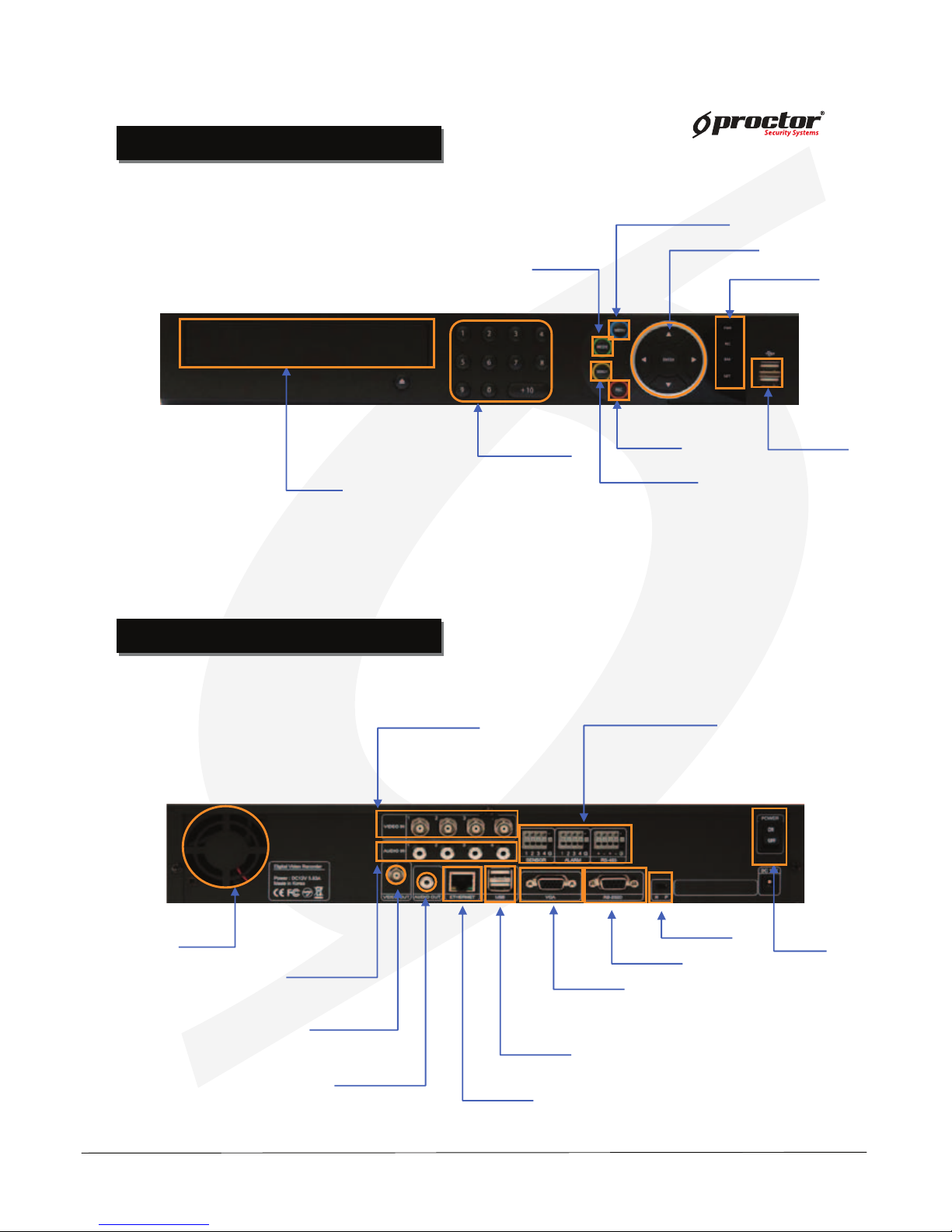
PRT 3004 / 3008 / 3016
Power adapter
connecting jacks
Audio IN
USB
Firmware upgrade USB back up
LAN(ETHERNET)
RS-485
Alarm/Sensor
VGA(Monitor)
Video OUT
Audio OUT
Video IN
PRT 3004 (4 Channels)
USB(Mouse)
Display network connections(CMS, WebCMS)
Record
Power
Remote control infrared receiver
Standalone DVR
User Manual Ver. 2.2
Power adapter
connecting jacks
Audio IN
USB
Firmware upgrade USB back up
LAN(ETHERNET)
RS-485
Alarm/Sensor
VGA(Monitor)
Video OUT
Audio OUT
Video IN
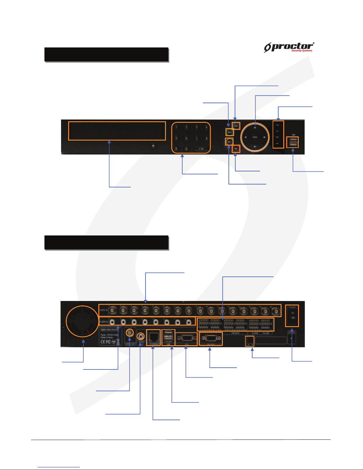
PRT 3016 (16 Channels)
Power adapter
Connecting jacks
Audio IN
USB
Firmware upgrade USB back up
LAN(ETHERNET)
RS-485
Alarm/Sensor
VGA(Monitor)
Video OUT
Audio OUT
Video IN
PRT 3008 (8 Channels)
REAR PANEL I/O Description
REAR PANEL I/O Description
REAR PANEL I/O Description
REAR PANEL I/O Description
Standalone DVR
User Manual Ver. 2.2
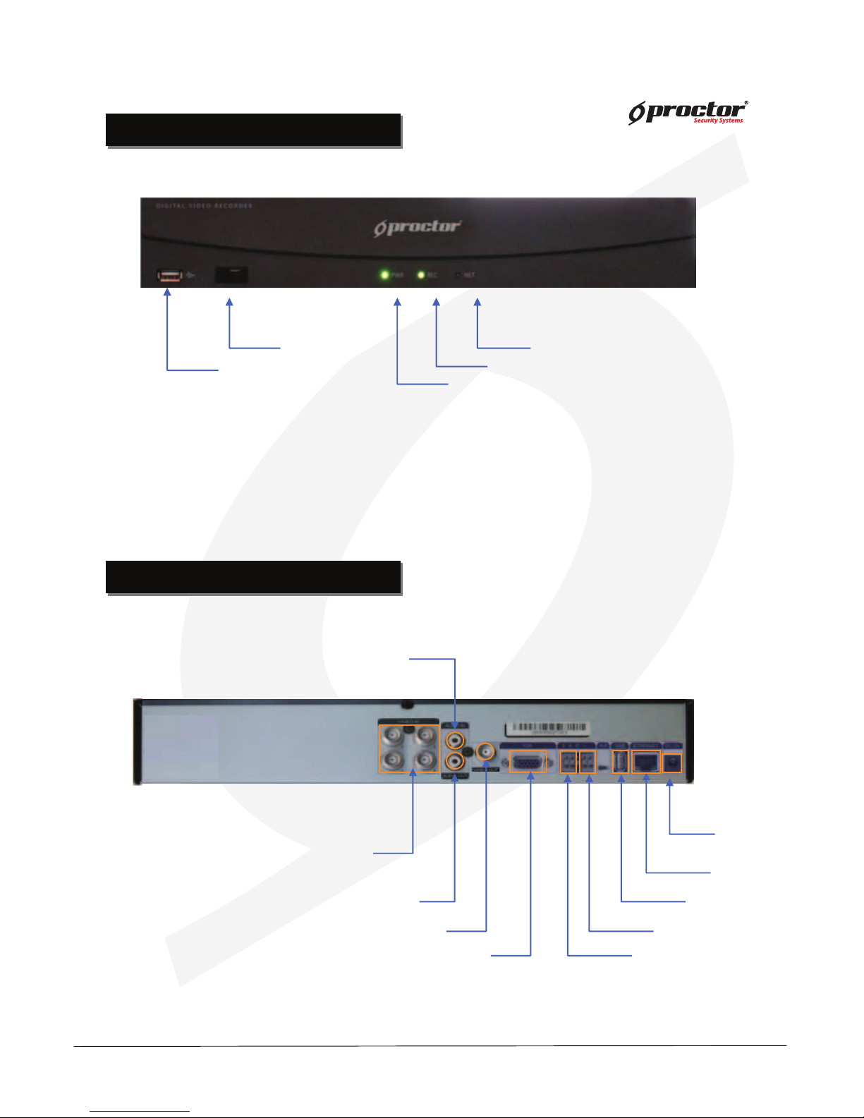
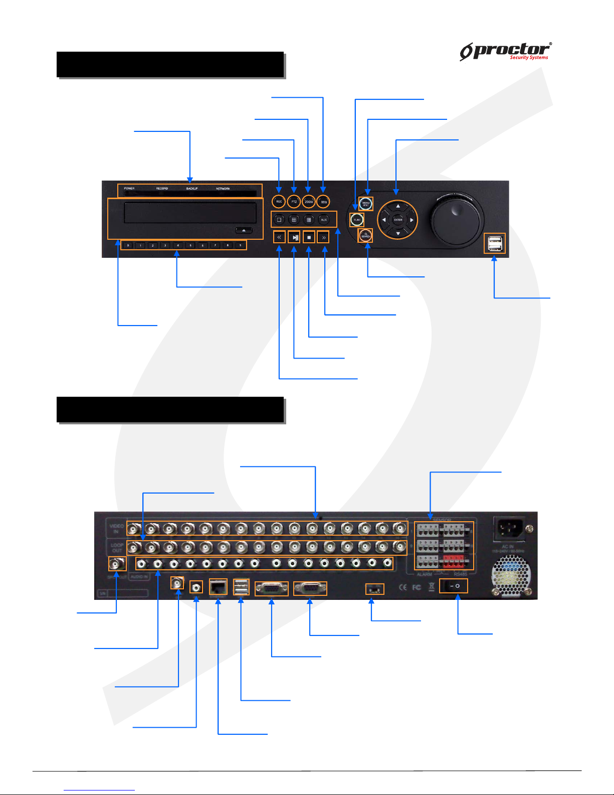
PRT 7004(4ch)
FRONT CASE BUTTON Description
FRONT CASE BUTTON Description
Menu button
Move button
USB Port:
2 PORT
USB port for using the
USB memory backup and
USD update
Setup/Record/Search/Backup/OSD
Move to setup & /Operate PTZ camera
CD-ROM
Indicate present system status information
Number buttons
(0 ~ +10)
Records images
Rec. button
Search button
Search saved data
Mode button
LED Indicator
Indicate present
system status information
REAR PANEL I/O Description
REAR PANEL I/O Description
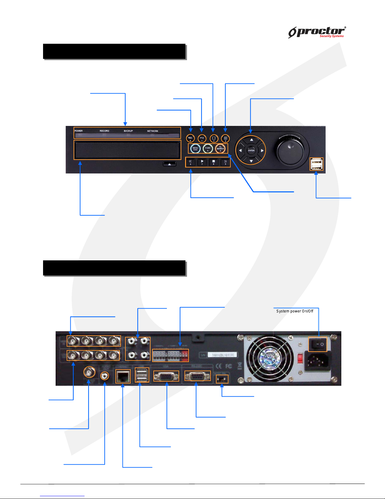
PRT 7004(4ch)
Power
System power On/Off
Camera video input
BNC 8 port
Audio Input
Alarm/Sensor/RS-485
Sensor(4port), Alarm(4Port)
RS-485 (2Port), GND(1Port)
FAN
Video output
Output video through
AV monitor
Audio Output socket
RS-232
Connect port for Program debugging
VGA
Computer monitor (VGA) port
ETHERNET
LAN port
USB
USB memory backup and USB upgrade
NTSC/PAL
Select NTSC or PAL mode

Standalone DVR
User Manual Ver. 2.2
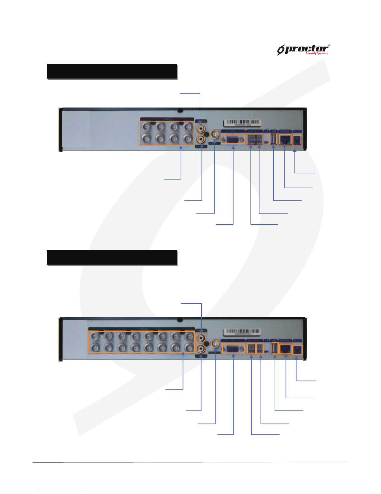
PRT 7008(8ch)
FRONT CASE BUTTON Description
FRONT CASE BUTTON Description
Menu button
Move button
USB Port:
2 PORT
USB port for using the
USB memory backup and
USD update
Setup/Record/Search/Backup/OSD
Move to setup & /Operate PTZ camera
CD-ROM
Indicate present system status information
Power
System power On/Off
Camera video input
BNC 8 port
Audio Input
Alarm/Sensor/RS-485
Sensor(8Port), Alarm(4Port)
RS-485 (2Port), GND(1Port)
FAN
Video output
Output video through
AV monitor
Audio Output socket
RS-232
Connect port for Program debugging
VGA
Computer monitor (VGA) port
ETHERNET
LAN port
USB
USB memory backup and USB upgrade
REAR PANEL I/O Description
REAR PANEL I/O Description
NTSC/PAL
Select NTSC or PAL mode
PRT 7008(8ch)
Number buttons
(0 ~ +10)
Records images
Rec. button
Search button
Search saved data
Mode button
LED Indicator
Indicate present
system status information
Standalone DVR
User Manual Ver. 2.2
PRT 7016(16ch)
FRONT CASE BUTTON Description
FRONT CASE BUTTON Description
REAR PANEL I/O Description
REAR PANEL I/O Description
PRT 7016(16ch)
Menu button
Move button
USB Port:
2 PORT
USB port for using the
USB memory backup and
USD update
Setup/Record/Search/Backup/OSD
Move to setup & /Operate PTZ camera
CD-ROM
Indicate present system status information
Number buttons
(0 ~ +10)
Records images
Rec. button
Search button
Search saved data
Mode button
LED Indicator
Indicate present
system status information
Power
System power On/Off
Camera video input
BNC 16 port
Alarm/Sensor/RS-485
Sensor(16port), Alarm(4Port)
RS-485 (2Port), GND(1Port)
FAN
Video output
Output video through
AV monitor
Audio Output socket
RS-232
Connect port for Program debugging
VGA
Computer monitor (VGA) port
ETHERNET
LAN port
USB
USB memory backup and USB upgrade
NTSC/PAL
Select NTSC or PAL mode
Audio Input
Standalone DVR
User Manual Ver. 2.2
PRT 9004 (4ch)
FRONT CASE BUTTON Description
FRONT CASE BUTTON Description
Menu/Function/Search
Rec. button/ 0
Move button/ ENTER
USB Port:
2 PORT
USB port for using the
USB memory backup and
USD update
Record images
Move to menu & setup button/Operate PTZ camera
CD-ROM
Menu/ESC
Function / 4
Search / 5
LED Indicator
1 division(full screen) / 2
PTZ. button / 1
Button function
Operate Pan/Tilt camera
4 division / 3
Indicate present system status information
Power
System power On/Off
Audio input Alarm/Sensor/RS-485
Video output
Output video through
AV monitor
Audio Output
RS-232
Connect port for Program debugging.
VGA
Computer monitor (VGA) port
ETHERNET
LAN port
USB
USB memory backup and USB upgrade
REAR PANEL I/O Description
REAR PANEL I/O Description
Channel video Input
NTSC/PAL
Select NTSC or PAL mode
PRT 9004 (4ch)
Play backward / 6
Play / 7
Stop / 8
Play forward / 9
Loop out
Sys
te
m power On
/O
Standalone DVR
User Manual Ver. 2.2
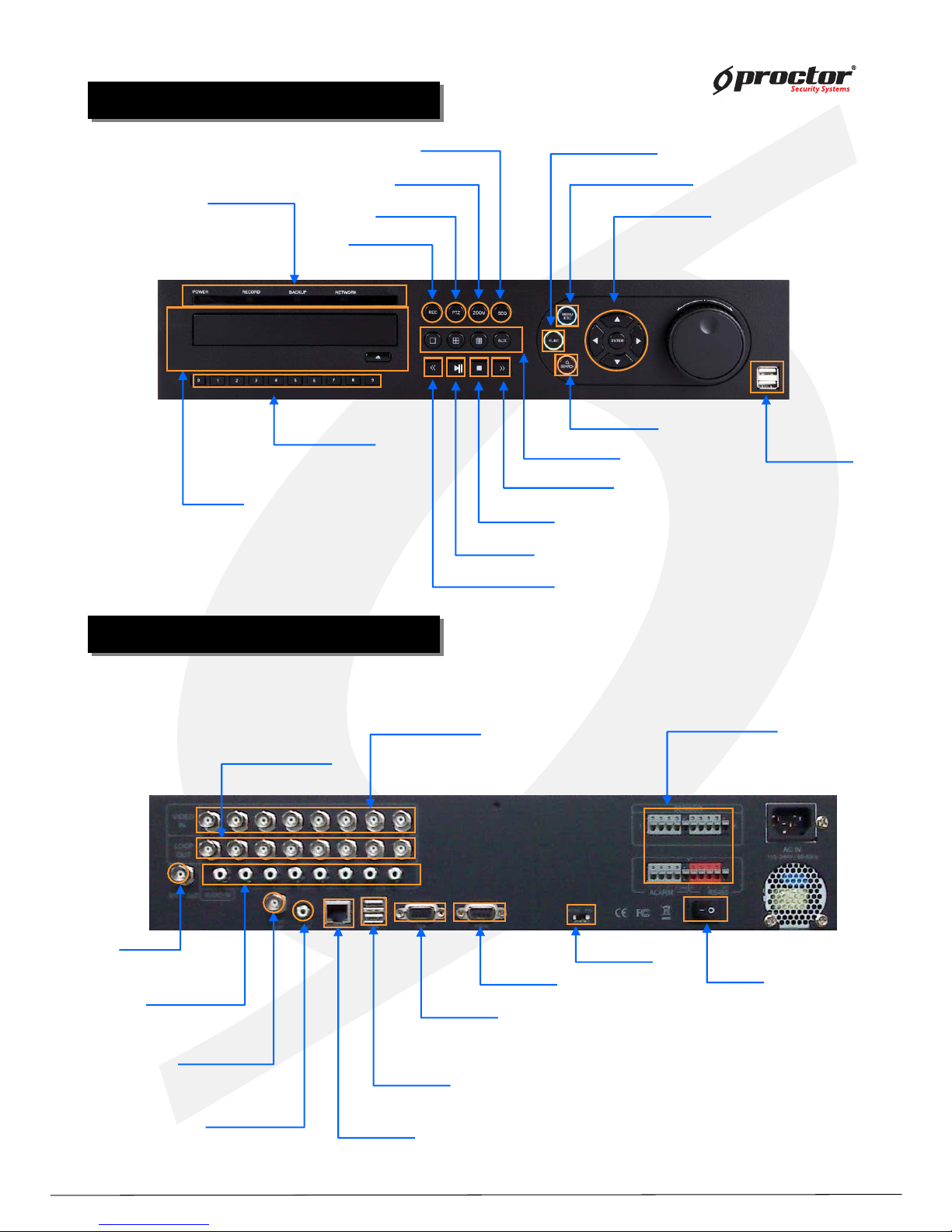
PRT 9008 (8ch)
FRONT CASE BUTTON Description
FRONT CASE BUTTON Description
Division button
Search button
Rec. button
Menu button
Move button
USB Port:
2 PORT
USB port for using the
USB memory backup and
USD update
Records images
Setup/Record/Search/Backup/OSD
Move to setup & /Operate PTZ camera
Number button
(0~9)
CD-ROM
Search saved data
LED Indicator
SEQ. button
Zoom button
PTZ. button
Play backward button
Stop button
Play forward button
Play forward on playback
Stop playback and converts to surveillance mode
Play backward on data playback
Division rotating surveillance button
Operate Pan/Tilt camera
PTZ/SPOT/Audio/Backup/Log view
Function button
Indicate present system status information
Play pause /play button
Play/Pause button
1ch,4ch,9ch,16ch division button
Power
System power On/Off
Camera video input
BNC 16 port
Audio Input
Alarm/Sensor/RS-485
Sensor(8port), Alarm(4Port)
RS-485 (2Port), GND(1Port)
SPOT Output
Video output
Output video through
AV monitor
Audio Output socket
RS-232
Connect port for Program debugging
VGA
Computer monitor (VGA) port
ETHERNET
LAN port
USB
USB memory backup and USB upgrade
REAR PANEL I/O Description
REAR PANEL I/O Description
Channel video output
Channel video output(Loop-out)
(75Ω AUTO)
NTSC/PAL
Select NTSC or PAL mode
PRT 9008 (8ch)
Standalone DVR
User Manual Ver. 2.2
PRT 9016 (16ch)
FRONT CASE BUTTON Description
FRONT CASE BUTTON Description
Division button
Search button
Rec. button
Menu button
Move button
USB Port:
2 PORT
USB port for using the
USB memory backup and
USD update
Records images
Setup/Record/Search/Backup/OSD
Moves to setup & /Operates PTZ camera
Number buttons
(0~9)
CD-ROM
Search saved data
LED Indicator
SEQ. button
Zoom button
PTZ. button
Play backward button
Stop button
Play forward button
Play forward on playback
Stop playback and converts to surveillance mode
Play backward on data playback
Division rotating surveillance button
Operates Pan/Tilt camera
PTZ/SPOT/Audio/Backup/Log view
Function button
Indicate present system status information
Play pause /play button
Play/Pause button
1ch,4ch,9ch,16ch division button
Power
System power On/Off
Camera video input
BNC 16port
Audio Input
Alarm/Sensor/RS-485
Sensor(16port),
Alarm(4Port)
RS-485 (2Port), GND(1Port)
SPOT Output
Video Output
Output video through
AV monitor
Audio Output socket
RS-232
Connect port for Program debugging
VGA
Computer monitor (VGA) port
ETHERNET
LAN port
USB
USB memory backup and USB upgrade
REAR PANEL I/O Description
REAR PANEL I/O Description
Channel video output
Channel video output(Loop-out)
(75Ω AUTO)
NTSC/PAL
Select NTSC or PAL mode
PRT 9016 (16ch)
Standalone DVR
User Manual Ver. 2.2
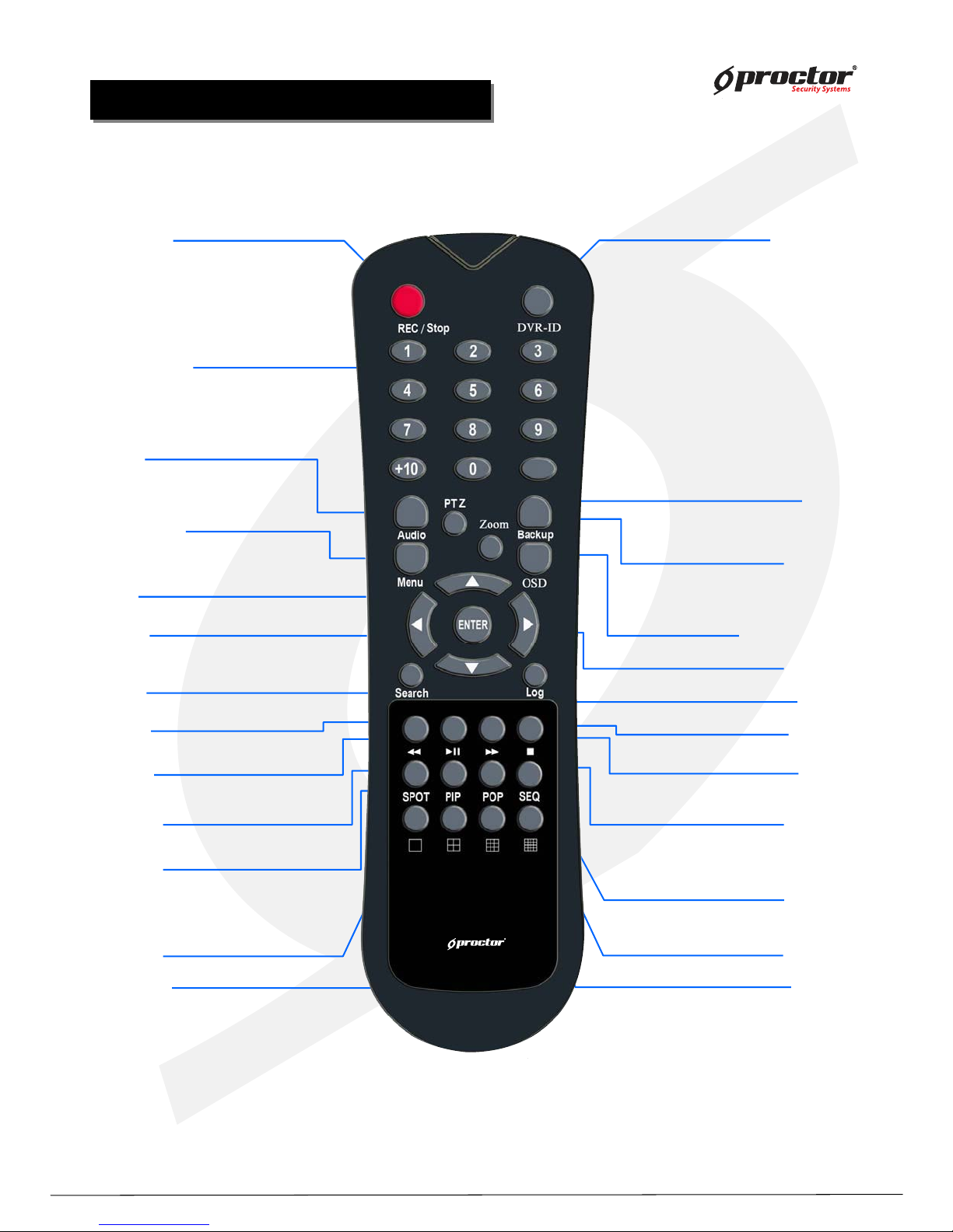
Remote Controller Button Description
Remote Controller Button Description
25) 16ch division button
1) Rec/Stop button
Records/stop images
2) DIV-ID button
Set DVR-ID
3) Numeric buttons
Applies setup details
and select channel
5) Menu button
Shows the menu. Moves
to upper menus and
complete setup
4) Audio button
Generates audio
through speaker
6) P/T button
Operates Pan/Tilt camera
7) Z/F button
Operates Zoom/Focus camera
8) Backup button
Backup saved images to
backup media
9 Division rotating surveillance button
1 division or 4 division rotating surveillance
10) Move button
Moves to setup and menu.
Operates PTZ camera.
11) Enter button
Inputs setup value.
12) Search button
Searches saved data
13) Log button
Shows DVR system logs
14) Play backward button
Max. x 128 play backward .
15) Pause button
Pause / playback the image
17) Stop button
Stops playback and converts to surveillance mode
16) Play forward button
Max. x 128 play forward.
Frame by frame play forward on playback
19) PIP button
18) SPOT button
SPOT monitor setup
20) POP button
22) 1ch division button
23) 4ch division button
24) 9ch division button
P/T
Z/F
21) SEQ button
Standalone DVR
12
Page:
User Manual Ver. 2.2
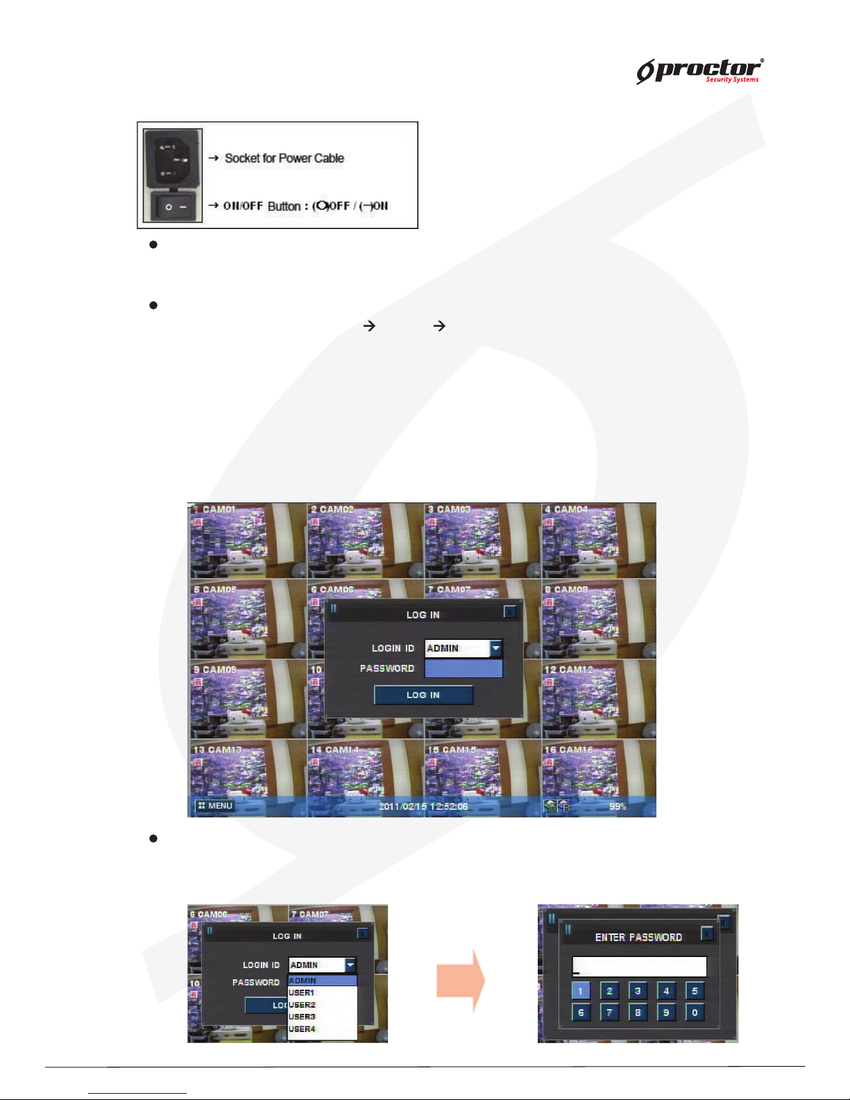
Power on/off
Power on
Press the power button at the back to be ‘ ON’ to turn it on after connecting the power cable.
* If you use this model with adapter, there is no power switch.
Power off
① press ‘ Menu’ button [ menu sy stem shutdown]
② select ‘ Shutdown’ and press ‘ ENTER/OK ’ button.
③ select ‘ ENTER/OK ’ button after the message “ system will shutdown” . Press ‘ENTER/OK ’
button.
④ press the power switch at the back to be ‘ Off’ .
Sy stem Log in
Input password
Input the password using number buttons at the password box .
☞
The default value is ‘0000’.
Standalone DVR
13
Page:
User Manual Ver. 2.2
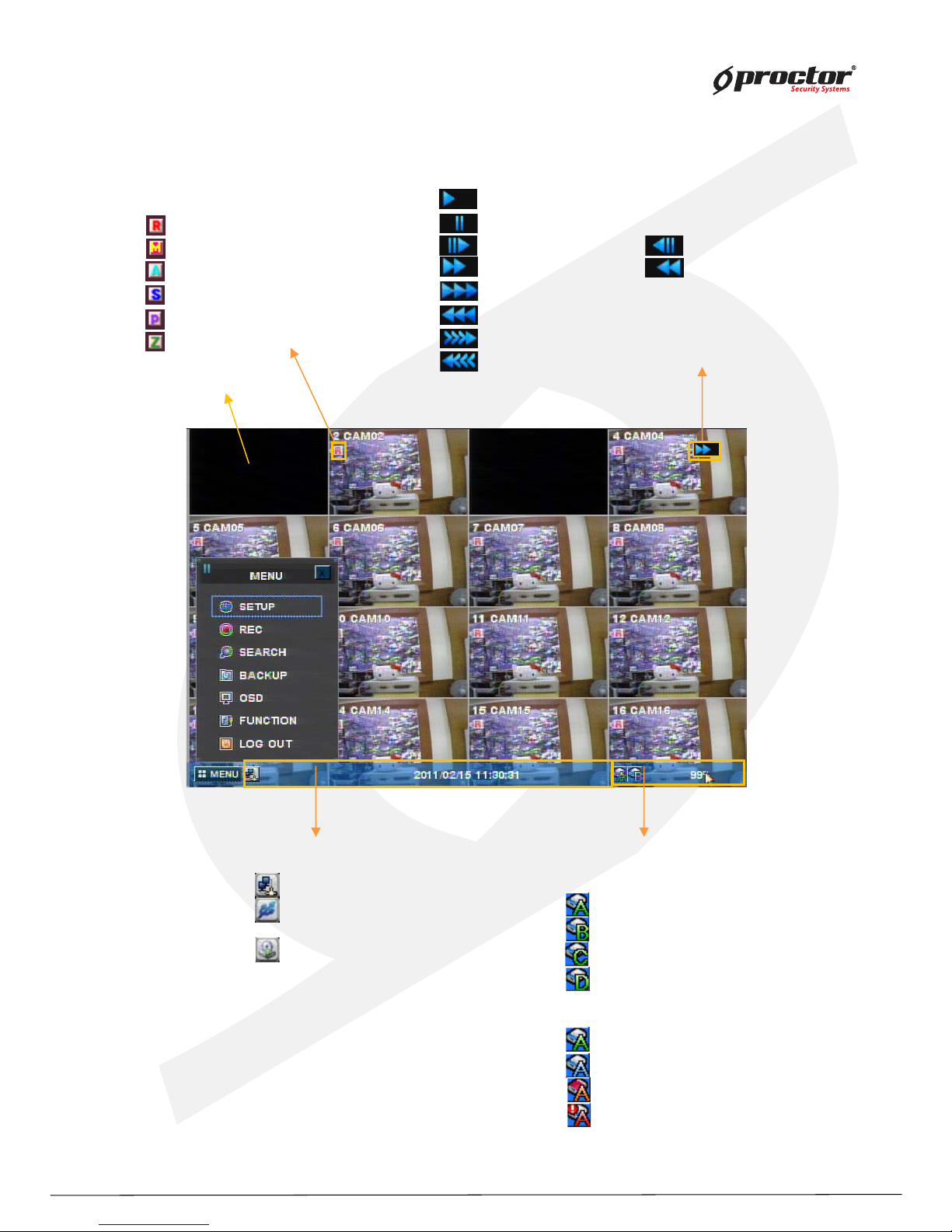
Screen display
[ Channel status ]
Channel number
Camera name
: Recording
: Motion detection in process
: Sensor detection in process
: Channel sequence indication
: PTZ indication
: Zoom button
[ Playback status ]
: Playback in progress
: Pause
: Playback per frame : Play backward per frame
: Speed playback : Speed play backward
: Double speed playback
: Double speed play backward
: Triple speed playback
: Triple speed play backward
[ HDD status ]
HDD indication
: hard disk#1
: hard disk#2
: hard disk#3
: hard disk#4
[ Status bar ]
: CMS connection status
: USB device connection status
Date & time
: Backup
* Coverted Channel
* color icon indications
Green : HDD installed & Active.
Blue : recording in progress
orange : Hard disk is full
red : Hard disk error
Standalone DVR
14
Page:
User Manual Ver. 2.2
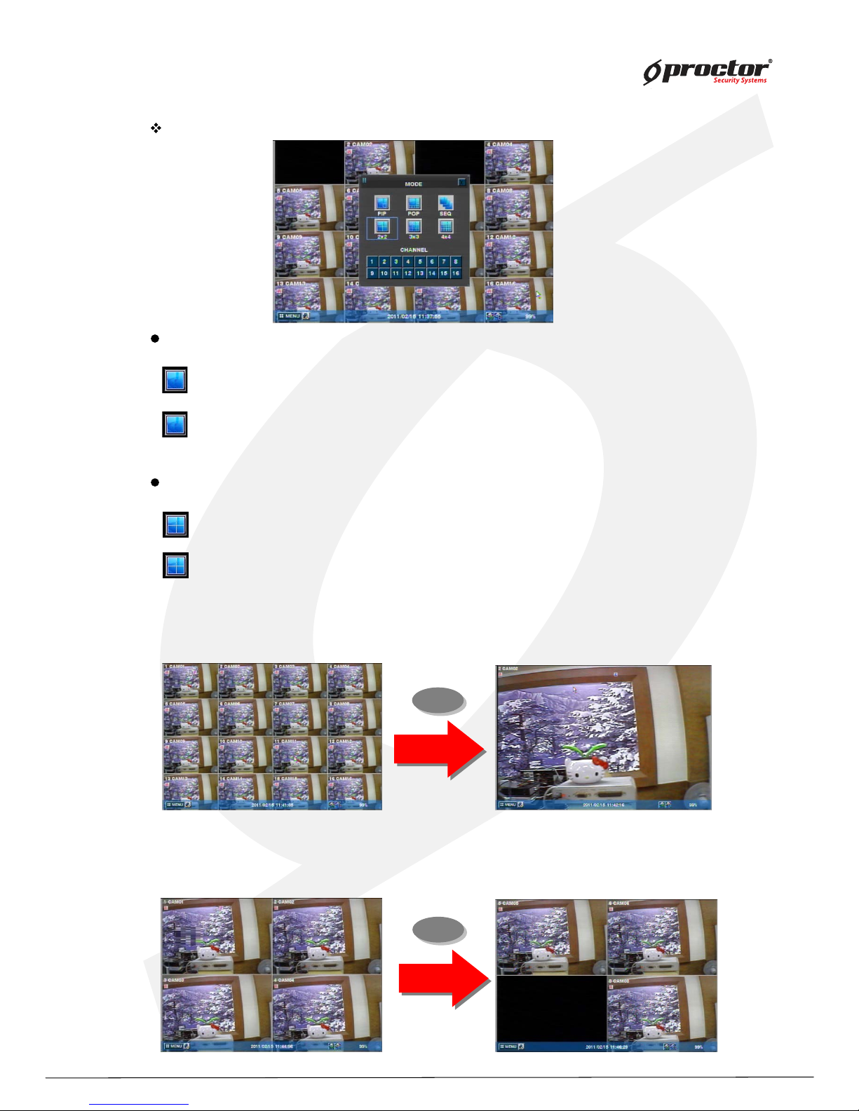
Full screen mode
- press this button.
- shifts to nex t channel each time you press this button.
Q uad screen mode
- press this button.
- shifts to the nex t channel each time you press this button.
- If you press a channel number button on remote- controller while
being displayed in the current q uad screen, the selected channel turns full screen.
MODE(Screen setup)
1
6
- If you press another channel number that is not being displayed in the current q uad screen, it turns
another q uad screen including the channel you selected.
CLICK right Mouse button(Only for 8 ch/1 6 ch product)
Standalone DVR
15
Page:
User Manual Ver. 2.2
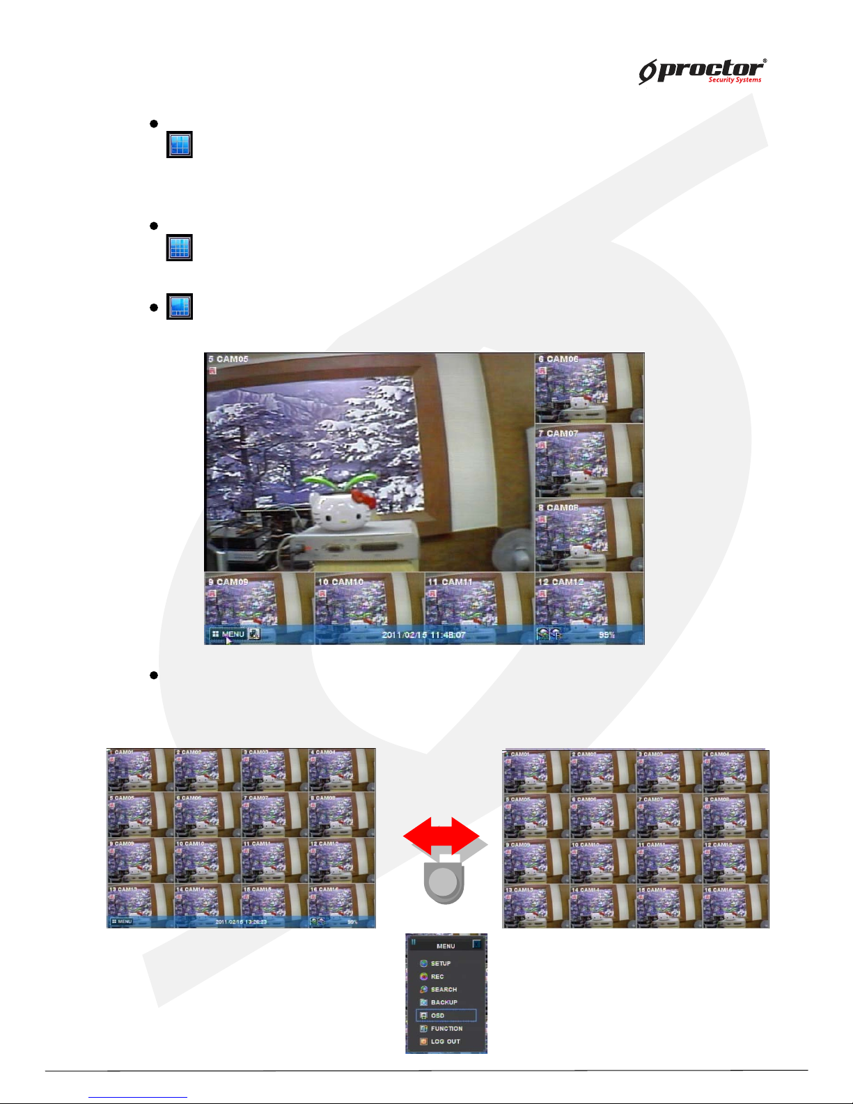
OSD button
9 division screen mode
- press this button
16 division screen mode
- press this button
POP screen mode * only for 8Ch & 16Ch products
- press ‘ POP’ button, it will display a certain channel larger than other channels.
OSD mode
- press ‘ OSD’ button, icons and channel status phrases will appear or disappear.
OSD
Standalone DVR
16
Page:
User Manual Ver. 2.2
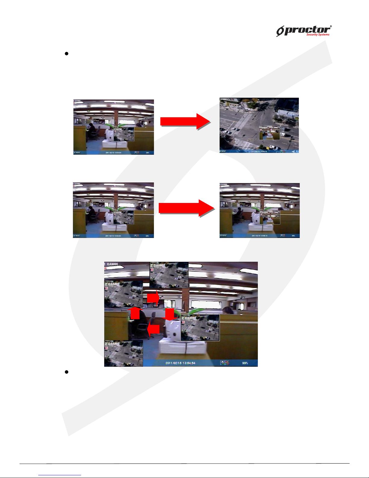
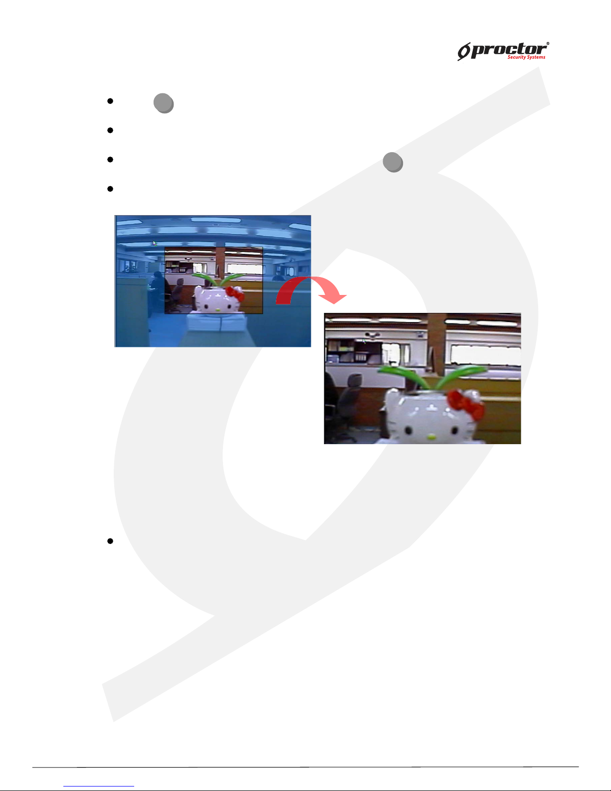
PIP screen mode
You can monitor 2 screens at the same time with small screen inside of one screen.
(1) press ‘PIP’ button on the remote control.
(2) press ‘PIP’ button one more time the display channels will be exchanged.
(3) If you press a channel number button on the controller, the channel will be displayed in
small screen.
Ex)
(4) you can move the small screen using arrow buttons.
Sequence playback screen mode
- If you press ‘SEQ’ button, full screen or quad screen will be displayed in sequence.
- you can setup duration time at system menu.
‘PIP’ Button
‘PIP’ Button
Cam ‘6’ Button
Cam ‘6’ Button
Standalone DVR
17
Page:
User Manual Ver. 2.2
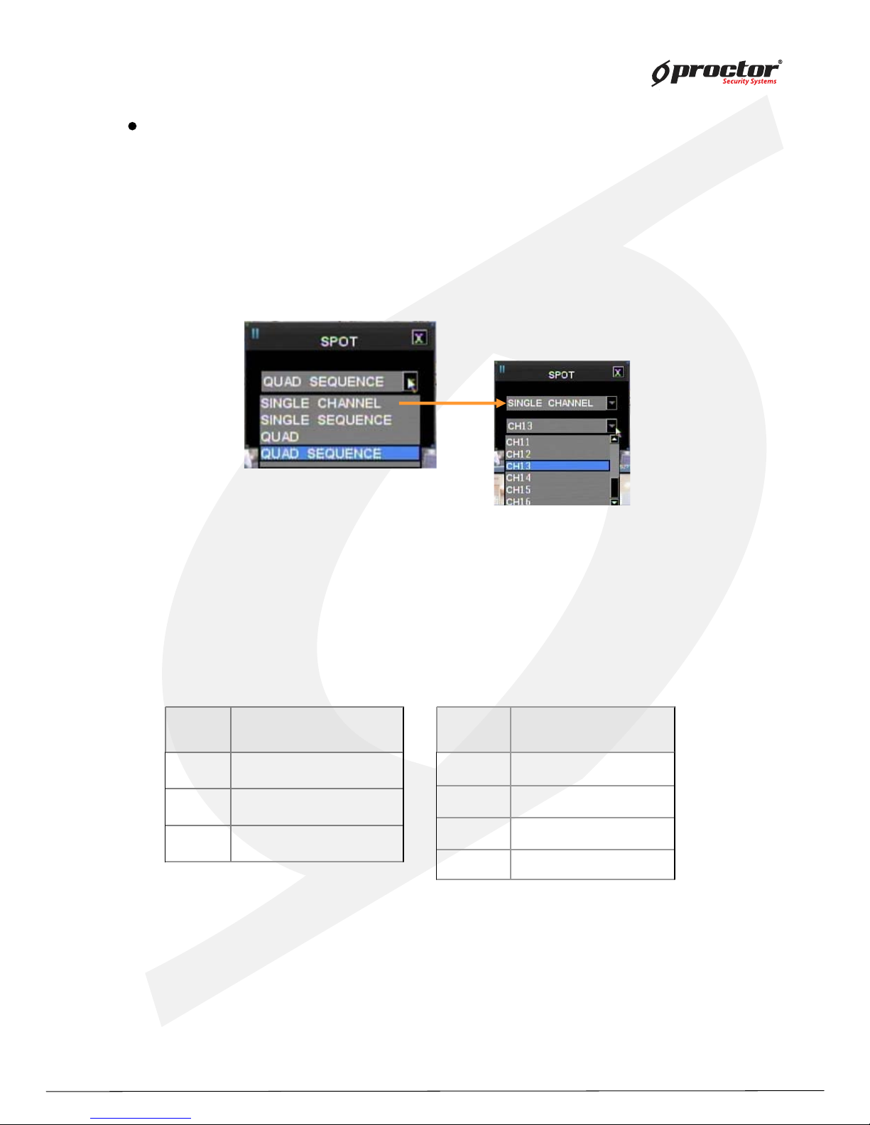
SPOT screen (This function is only for 8008 and 8016 DVR)
Display real time screen of another screen- mode in different monitor using ‘ SPOT OUT’ port
at the back of product.
Press ‘ Function’ button and select ‘ Spot’ to set up ‘ SPOT’ screen.
(1 ) type
① single channel
playback only one selected channel in full screen mode.
② seq uence single
playback each channel in full screen mode in seq uence.
you can setup duration time at system menu.
③ seq uence q uad
playback channels in q uad screen mode in seq uence.
[ 8008]
[ 8016]
you can setup duration time at system menu.
No. Camera
1 Camera 1 ~ Camera 4
2 Camera 5 ~ Camera 8
3 Camera 6 ~ Camera 9
Quad No. Camera
1 Camera 1 ~ Camera 4
2 Camera 5 ~ Camera 8
3 Camera 9 ~ Camera 12
4 Camera 13~ Camera 16
Standalone DVR
18
Page:
User Manual Ver. 2.2
press (ZOOM) button in full screen mode to active digital z oom.
z oomed area moves as you press arrow buttons.
siz e of z oomed area gets bigger and smaller as you press (ZOOM ) button one more time.
press ‘ ENTER/OK ’ button, it shows the selected area bigger like the images below.
Dig ital z oom
Z/F
Z/F
Recording
press ‘ REC’ button to start recording.
Check before recording !!
(1 ) Check if hard disk is formatted.
(2) Check the camera output.
(3 ) Check if each channel names are correct.
(4 ) Set each channel’s recording q uality.
(5) Set each channel’ s recording frames.
Standalone DVR
19
Page:
User Manual Ver. 2.2
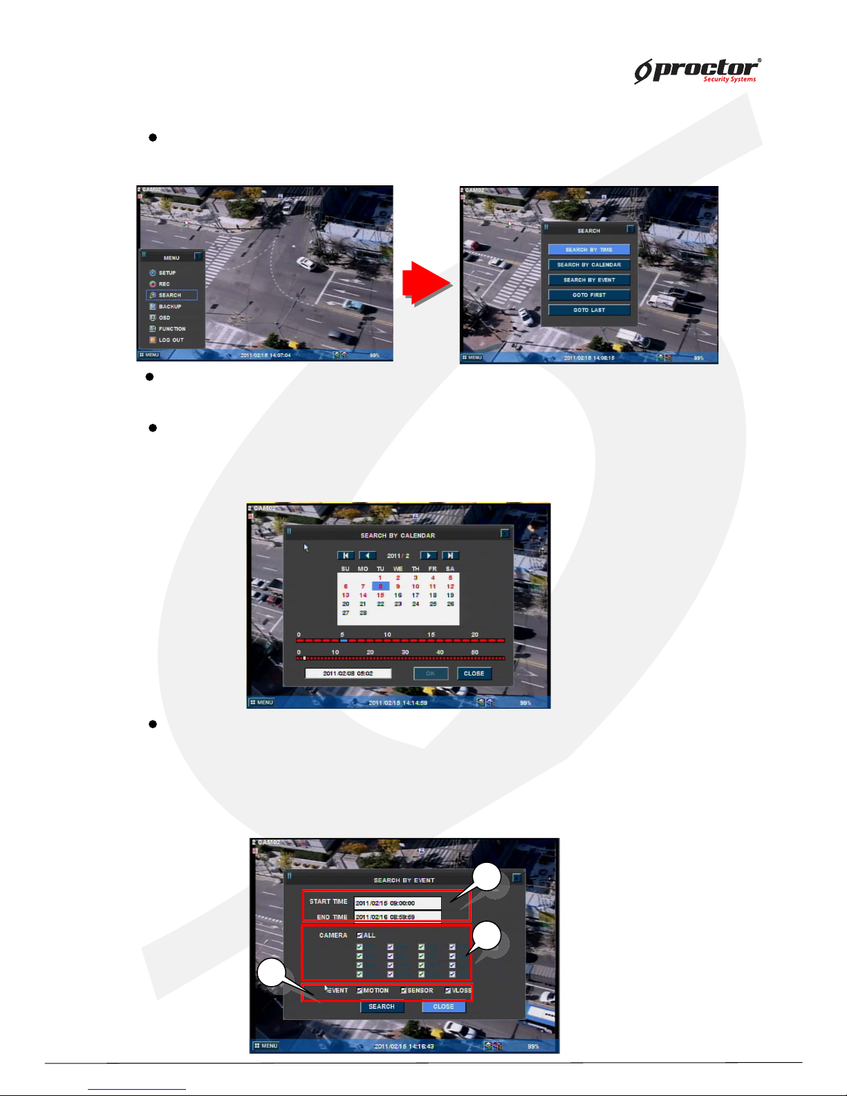
Search
Search by calendar
(1 ) you can see ‘ calendar’ menu like below if you select ‘ Search by calendar’ .
(2) select the date and time using arrow keys. Press ‘ ENTER/OK ’ button.
(3 ) lastly, select ‘ ENTER/OK ’ and press ‘ ENTER/OK button’ .
Search by time
(1 ) input the date and time to search. Press ‘ ENTER/OK ’ button.
Search by event
(1 ) you can see the menu like below if you select ‘Search by event’ .
(2) input the beginning date/time and ending date/time to search.
(3 ) select channels to search.
(4 ) select events to search.
(5) lastly, select search and press ‘ ENTER/OK ’ button.
2
2
2
3
3
3
4
4
press ‘ SEARCH’ button. Then y ou can see the ‘ Search’ menu lik e below.
Standalone DVR
20
Page:
User Manual Ver. 2.2
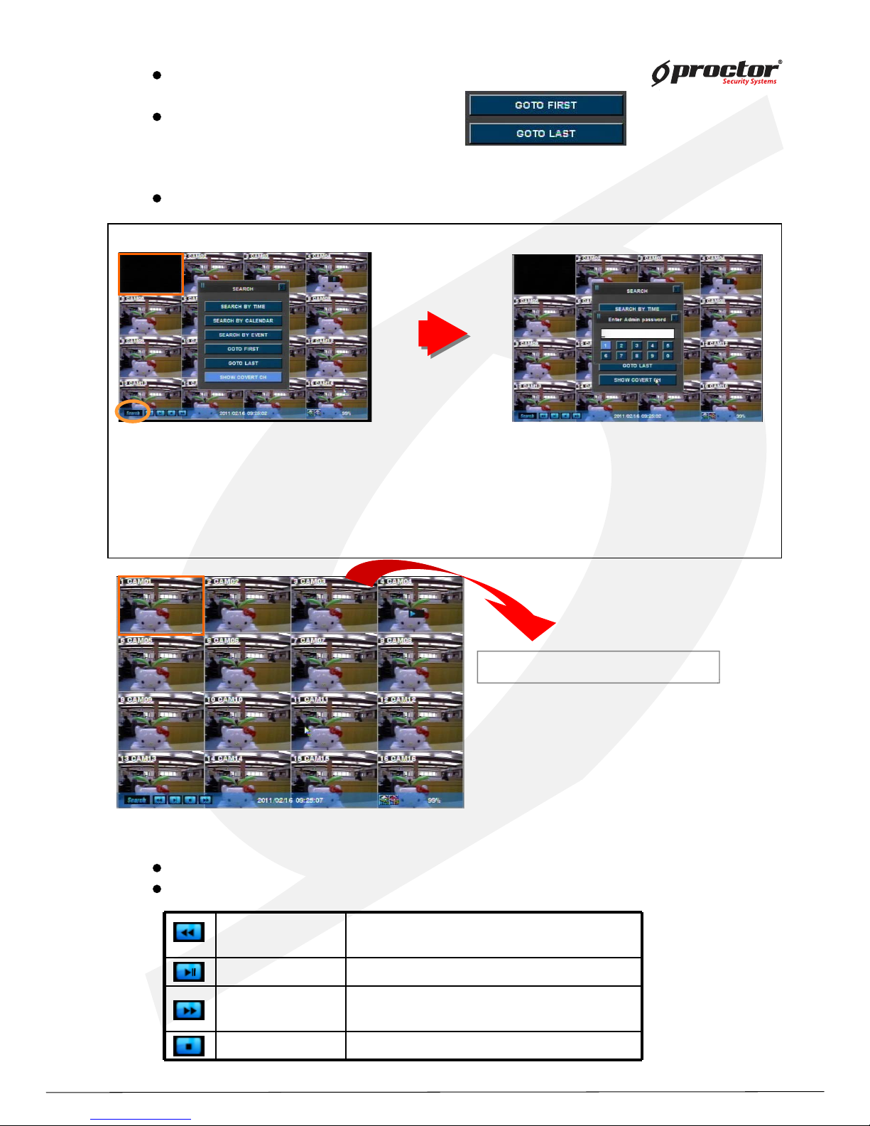
Playback
press ‘Playback’ button to start playback from the recent part of recording.
you can choose various playback screen modes by screen mode buttons.
◀◀
Rewind
Frame playback
- Rewind during playback.
- Playback by frame during pause.
▶ Playback Playback and pause the recorded screen.
▶▶
Fast forward
Frame playback
-Fast forward during playback.
-Playback by frame during pause.
■ stop Stop the playback.
0000
Go to first
playback from the beginning part of recorded.
Go to last
playback from the recent part of recorded.
How to view ‘Covert-on (Hidden)’ channel
Click this icon,
Or ‘Search’ button at the front panel.
Or ‘Search’ button in remote controller
Select ‘SHOW HIDDEN CH’.
Hidden channels will be displayed.
Standalone DVR
21
Page:
User Manual Ver. 2.2
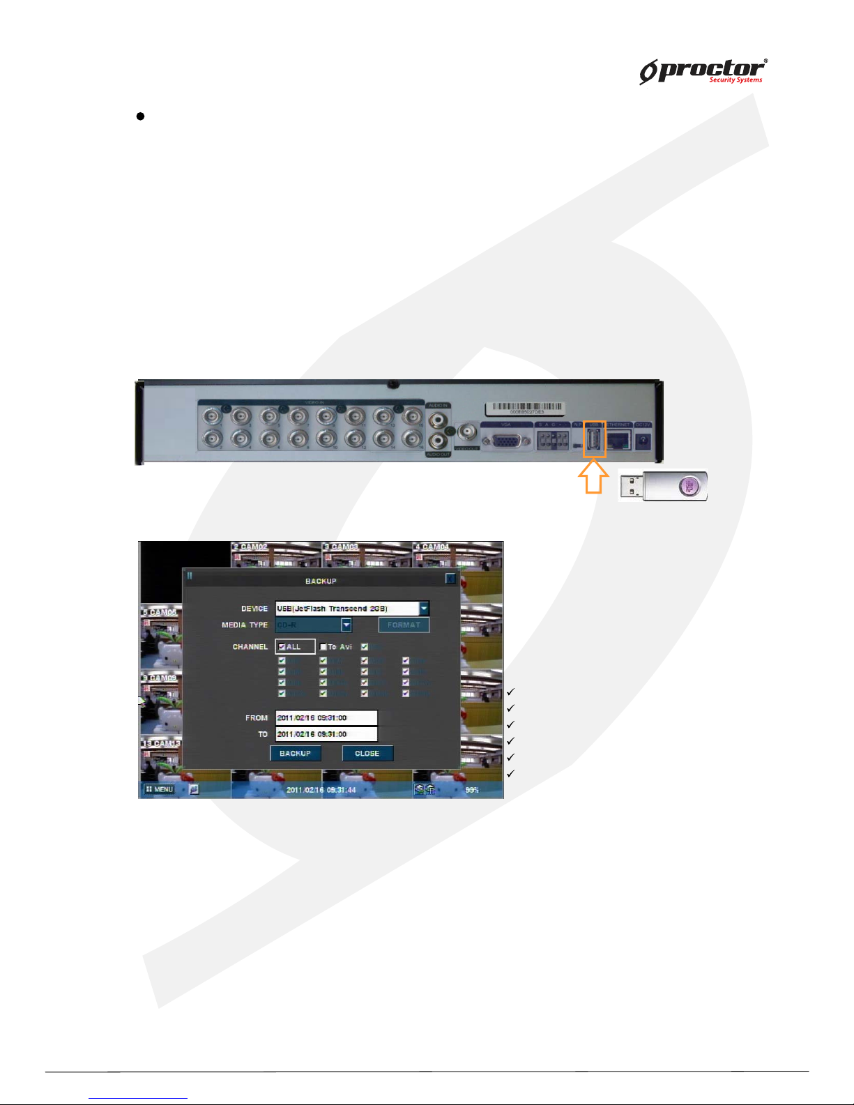
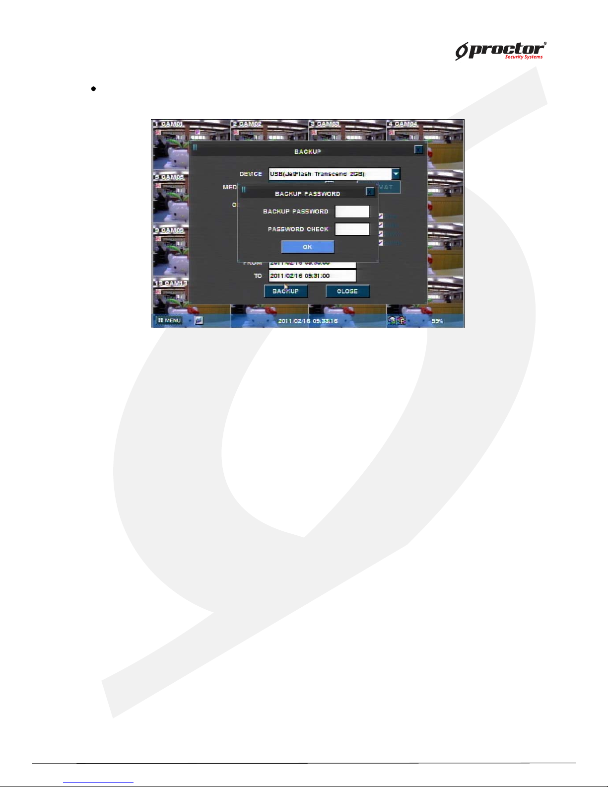
backup data using USB Memory stick.
(2) Press ‘Function’ button and select ‘Backup’
(3) Select options from menu.
DEVICE – select the device to backup.
MEDIA TYPE– select media ‘CD’,’DVD’ etc to backup.
FORMAT – format the media before backup.
CHANNEL – select channels to backup.
FROM – input the date/time to start backup.
TO – input the date/time to finish backup.
(4) Select ‘BACKUP’ and press ‘ENTER/OK’ button.
(5) Backup password window will show up and ask you to input the password. You must remember
this password, and you will be asked to input this password when you playback the data.
NOTE: 1) Both Admin and user can backup the data with this function. Admin can backup and
playback the hidden camera data, but user can’t access to backup the hidden camera data.
2) Backup password is not related with DVR passw
ord, you can input the virtual password
for backup only, and it must be 4 digit numbers.
3) This function is available from the DVR firmware version, 090427-q2g8 and BackupViewer
V1.0.9.420.
Backup data protection with virtual password
There are two ways to backup.
A. How to back up the original data for all or some channels .
Backup file can be run as a backup viewer in this way.
To back up, you should input a back up password.
B. AVI back up
AVI back up must useUSB memory. Also you can only back up for a single channel.
You can play for Window system on your PC as for AVI backed up file.
You do not have to input a back up password when you back up for AVI .
Note: When you play AVI backup dat
a, some the PC s need H.264 codec.
Standalone DVR
22
Page:
User Manual Ver. 2.2
Note : If 20XX model, Data backup must be used USB memory stick and back panel’s USB port.
1) You can backup a hidden channel while logged in as an Admin.
2) If logged in as a general User, hidden channels cannot be backed up.
Standalone DVR
23
Page:
User Manual Ver. 2.2
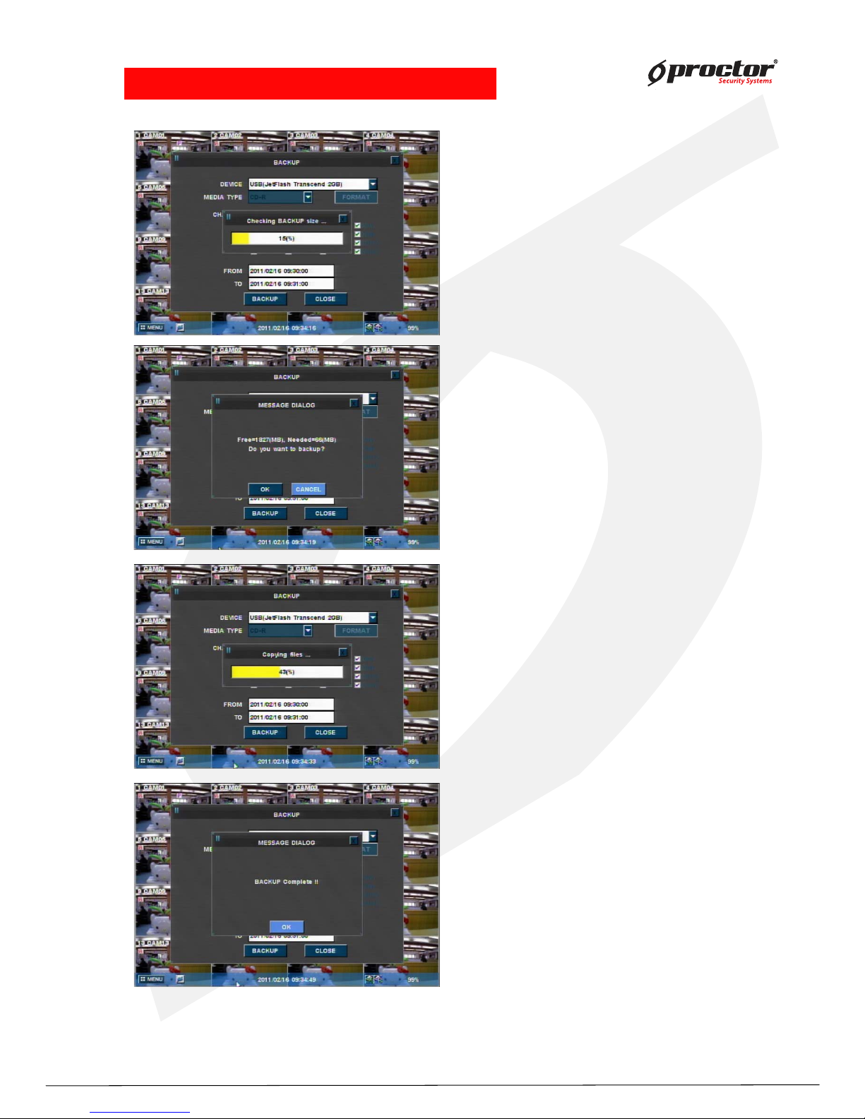
•NOTE: Do not remove USB device during Backup!.
• Checking backup file size
Note:
If back up size is small, you cannot view
progress rate.
2) File storage display
3) Copy files progress
4) Back up complete
Standalone DVR
24
Page:
User Manual Ver. 2.2
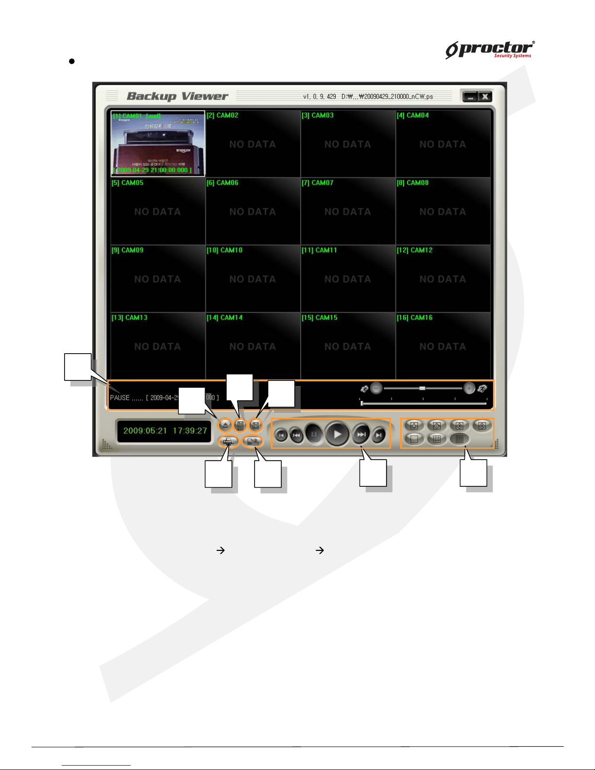
(1 ) Open file: Load the backup data.
(2) AVI: save the selected channel to avi during playback
Select channel
click this icon(start) click again(finish)
(3 ) Save: save the playback images as bmp file.
(4 ) Print screen image
(5) W atermark: check if there is any modification of data.
(6 ) Playback: playback the backup data. (playback, pause, speed playback, playback by
frame)
(7 ) Division: 1 division, 4 division, 9 division, 1 6 division
(8 ) Status box : display the status of backup viewer.
Back up viewer
8
8
8
6
6
6
7
7
7
4
4
4
4
5
5
5
3
3
3
1
1
2
2
Standalone DVR
25
Page:
User Manual Ver. 2.2
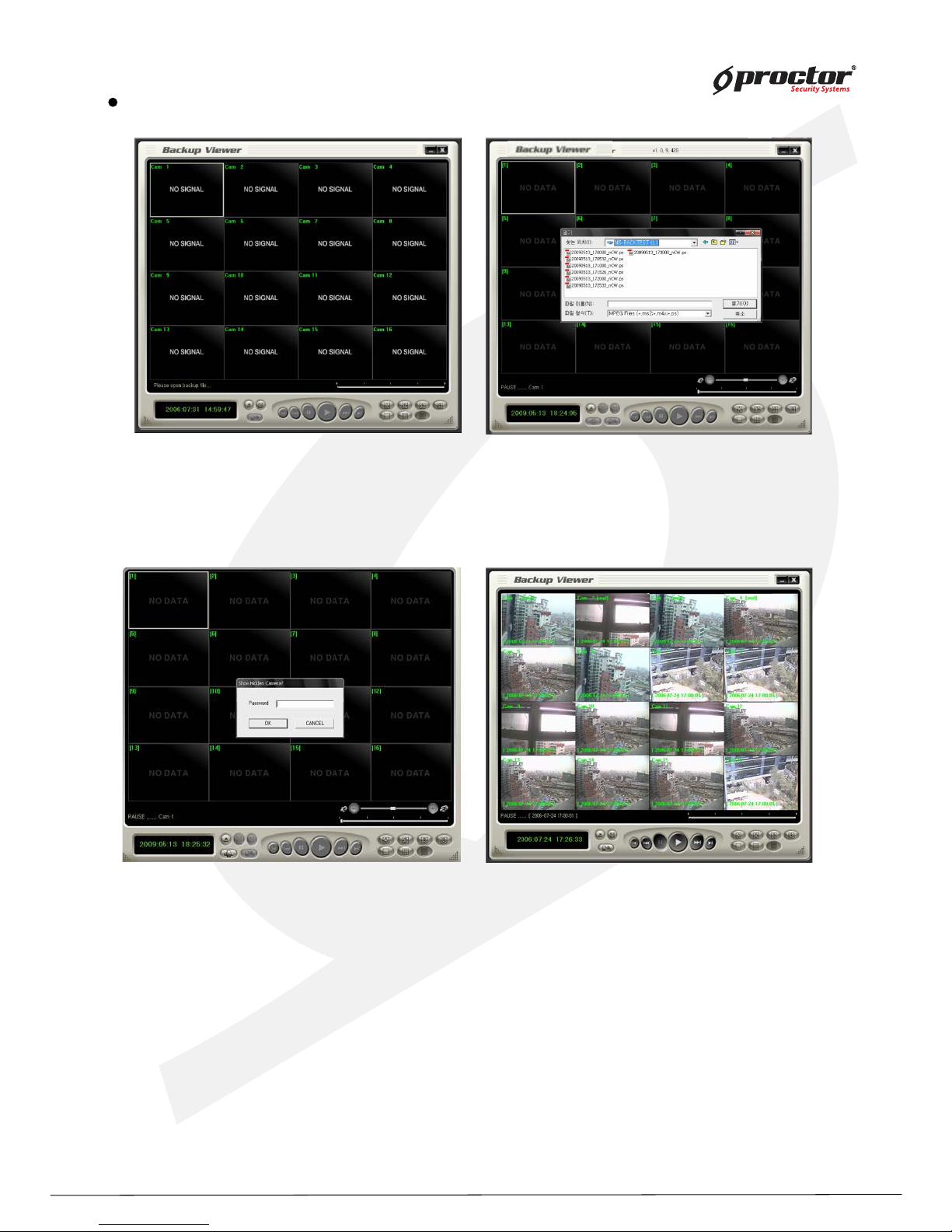
(1) Click ‘Open file’ button from the main screen.
(2) Select files to playback.
(3) Input
backup password
backup password
Open file
NOTE: 1) Both Admin and user can backup the data with this function. Admin can backup and
playback the hidden camera data, but user can’t access to backup the hidden camera data.
2) Backup password is not related with DVR password, you can input the virtual password
for backup only, and it must be 4 digit numbers.
3) This function is available from the DVR firmware version, 090427-q2g8 and BackupViewer
V1.0.9.420.
(4) After it completes to load the backup file, you can playback
it, and save it as bmp files.
 Loading...