

Page 1
Standalone
DVR
USER MANUAL
Page 2

2
Page :
Content s
Content s
Chapter 1 Service Requirement
Chapter 2 Product Information
Chapter 3 Basic Pr oduct Operation
Chapter 4 System Setup
4
5
7
37
Power on/of f
17
System Login
17
Screen display
18
MODE(Screen setup)
19
Digit al Zoom
23
Recording
23
Search
24
Playback
25
Backu p
26
PTZ
33
Audio
35
Log View
35
Remote-control ID
36
SPOT
34
Sequence
36
Display
40
CAMERA
44
RECORD
49
EVENT
52
STORAGE
59
NETWORK
61
SYSTEM
66
Chapter 5 Firmware Upgrad e 71
Chapter 6 CMS – Display Mode 74
CMS – Setup Mode 84
CMS – Search Mode 99
Standalone DVR
Security Systems
Page 3

Standalone DVR
3
Page:
User Manual V er . 2.2
129
Chapter 7 CMS – EMAP Editor/Viewer
110
Chapter 9 Web CMS 127
Chapter 8 CMS – Remote Update 120
Chapter 12 Specification
140
Chapter 11
135
Chapter 13 Warranty
143
Chapter 10
Mobile access
MISC
Page 4

Standalone DVR
4
Page:
User Manual Ver. 2.2
Chapter 1
Limitation of warranty
We warrant that Standalone DVR series will be free from defects in materials and workmanship
under normal use and service for all parts excluding hard drives for a period of one year after
the date that the customer purchased the product.
If such a defect occurs, you should contact where you purchased and return the product to us
accompanied with the proof of purchase, we will either repair or replace the product through
our inspection. It is your exclusive remedy for breach of this warranty. However this warranty
shall not apply on repairs or replacements necessitated by any cause as listed below.
1) improper i
nstallation
2) acts of nature
3) accident
4) lack of proper maintenance
5) voltage fluctuations
6) unauthorized repair or modifications.
For more details on the limitation of warranty, refer to entire limited warranty as appendix at
the end of this manual.
Service Information
• To avoid additional defects, do not attempt to repair this unit by yourself. Please contact
a Standalone local dealer/distributor/certified installer to getservice from authorized
technician. Unauthorized repairs will void the warrantee, may result in fire, electronic
shock or other hazards.
• All shipment for repair should be prepaid and properly packed with a note outlining the
defec
t.
• Send the product with purchase number or other related documents obtaining from Fore
Tech or its agent as proof purchasing the product.
Service Requirement
Page 5

Standalone DVR
5
Page:
User Manual Ver. 2.2
Chapter 2 Product Information
Enable integrated video monitoring and system management by networking with maximum
1000DVRs systems through CAMS(Central Automated Monitoring System) interface.
High quality video display and system stability through embedded operating system with
hardware H.264 video compression chip.
Support the max D1(720*480) quality resolution video display and 480FPS recording.
16 CH video input and 16CH audio input.
Triplex multitasking for video recording, playback, transmission and backup.
Easy operation using remote-controller, full-page panel, GUI support.
Network transmission of 30 different types of system error management information per
system.
High-speed transmitted video monitoring of ST DVRs up to 64 channels through CMS
software network.
High-speed network video monitoring by internet explorer through WEB CMS server within
the system.
Features
Watchdog function for hardware & software error
Robust design for physical impact and temperature
Generating 30 different types of network massages for system errors.
Application of low power and low heat features for industrial environment
System Design
Advanced hardware H.264
Embedded O/S ROM
MAX 16 Camera input
Auto-sequence screen division and PIP/POP function.
Real time display
Recording : 480fps-NTSC (PAL 400fps)
4 CH ~ 16CH audio recording and two way audio communication.
CD, DVD RW, USB external saving devices
Ethernet 10/100Mbps, RS-232C network support
Maximum 16 ports sensor input and 4 port alarm output
Triplex multitasking, recording, playback, backup and network.
STATIC, DHCP, PPPOE support
General Specifications
Page 6

Standalone DVR
6
Page:
User Manual Ver. 2.2
Firmware upgrade using network and USB port.
Remote upgrade using CMS
Free alarm (max 30secs), port alarm (max 120secs) recording
Watermarking
Private backup viewer
E-Map’s layout mapping
able to install maximum 4 HDDs or 1 ODD and 3HDDs(80XX series only)
User friendly interface by USB mouse control
Page 7
Standalone DVR
User Manual Ver. 2.2
Chapter 3 Basic Product Operation
Page 8
Standalone DVR
User Manual Ver. 2.2
FRONT CASE Button Description
FRONT CASE Button Description
REAR PANEL I/O Description
REAR PANEL I/O Description
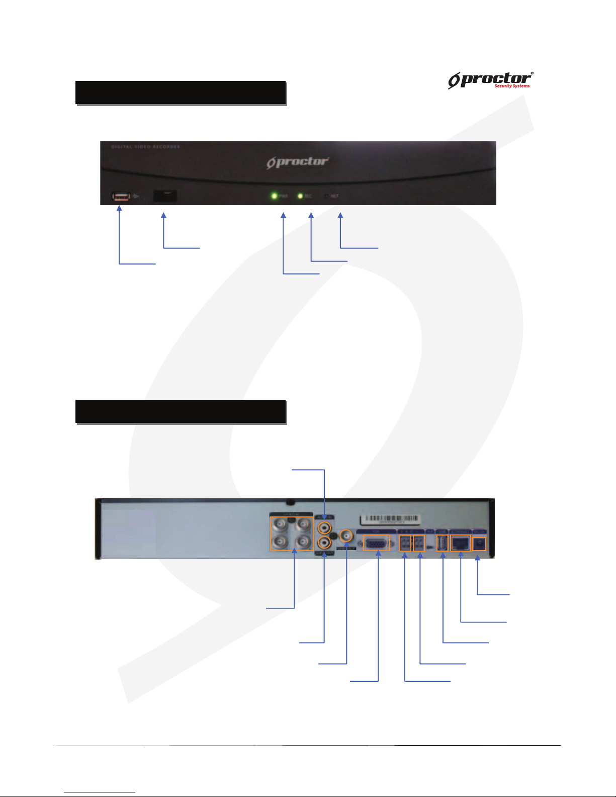
PRT 3004 / 3008 / 3016
Power adapter
connecting jacks
Audio IN
USB
Firmware upgrade USB back up
LAN(ETHERNET)
RS-485
Alarm/Sensor
VGA(Monitor)
Video OUT
Audio OUT
Video IN
PRT 3004 (4 Channels)
USB(Mouse)
Display network connections(CMS, WebCMS)
Record
Power
Remote control infrared receiver
Page 9
Standalone DVR
User Manual Ver. 2.2
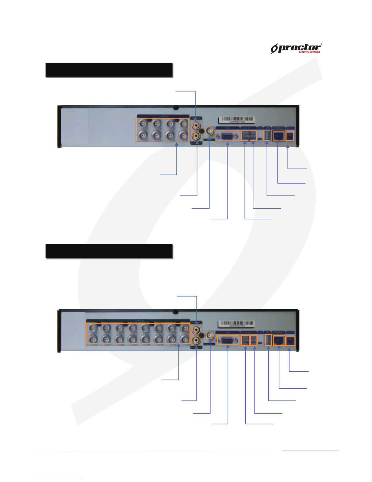
Power adapter
connecting jacks
Audio IN
USB
Firmware upgrade USB back up
LAN(ETHERNET)
RS-485
Alarm/Sensor
VGA(Monitor)
Video OUT
Audio OUT
Video IN
PRT 3016 (16 Channels)
Power adapter
Connecting jacks
Audio IN
USB
Firmware upgrade USB back up
LAN(ETHERNET)
RS-485
Alarm/Sensor
VGA(Monitor)
Video OUT
Audio OUT
Video IN
PRT 3008 (8 Channels)
REAR PANEL I/O Description
REAR PANEL I/O Description
REAR PANEL I/O Description
REAR PANEL I/O Description
Page 10
Standalone DVR
User Manual Ver. 2.2
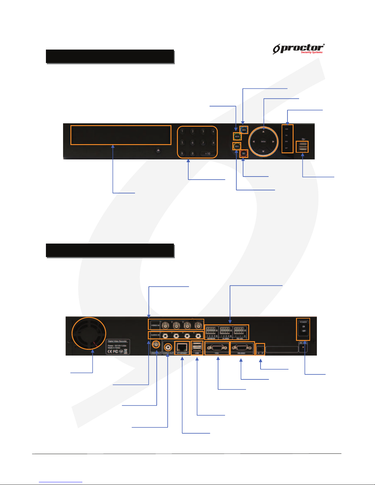
PRT 7004(4ch)
FRONT CASE BUTTON Description
FRONT CASE BUTTON Description
Menu button
Move button
USB Port:
2 PORT
USB port for using the
USB memory backup and
USD update
Setup/Record/Search/Backup/OSD
Move to setup & /Operate PTZ camera
CD-ROM
Indicate present system status information
Number buttons
(0 ~ +10)
Records images
Rec. button
Search button
Search saved data
Mode button
LED Indicator
Indicate present
system status information
REAR PANEL I/O Description
REAR PANEL I/O Description
PRT 7004(4ch)
Power
System power On/Off
Camera video input
BNC 8 port
Audio Input
Alarm/Sensor/RS-485
Sensor(4port), Alarm(4Port)
RS-485 (2Port), GND(1Port)
FAN
Video output
Output video through
AV monitor
Audio Output socket
RS-232
Connect port for Program debugging
VGA
Computer monitor (VGA) port
ETHERNET
LAN port
USB
USB memory backup and USB upgrade
NTSC/PAL
Select NTSC or PAL mode
Page 11

Standalone DVR
User Manual Ver. 2.2
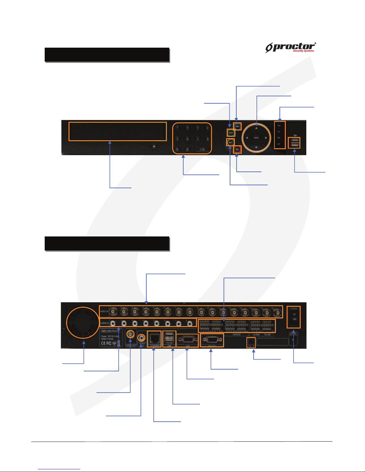
PRT 7008(8ch)
FRONT CASE BUTTON Description
FRONT CASE BUTTON Description
Menu button
Move button
USB Port:
2 PORT
USB port for using the
USB memory backup and
USD update
Setup/Record/Search/Backup/OSD
Move to setup & /Operate PTZ camera
CD-ROM
Indicate present system status information
Power
System power On/Off
Camera video input
BNC 8 port
Audio Input
Alarm/Sensor/RS-485
Sensor(8Port), Alarm(4Port)
RS-485 (2Port), GND(1Port)
FAN
Video output
Output video through
AV monitor
Audio Output socket
RS-232
Connect port for Program debugging
VGA
Computer monitor (VGA) port
ETHERNET
LAN port
USB
USB memory backup and USB upgrade
REAR PANEL I/O Description
REAR PANEL I/O Description
NTSC/PAL
Select NTSC or PAL mode
PRT 7008(8ch)
Number buttons
(0 ~ +10)
Records images
Rec. button
Search button
Search saved data
Mode button
LED Indicator
Indicate present
system status information
Page 12
Standalone DVR
User Manual Ver. 2.2
PRT 7016(16ch)
FRONT CASE BUTTON Description
FRONT CASE BUTTON Description
REAR PANEL I/O Description
REAR PANEL I/O Description
PRT 7016(16ch)
Menu button
Move button
USB Port:
2 PORT
USB port for using the
USB memory backup and
USD update
Setup/Record/Search/Backup/OSD
Move to setup & /Operate PTZ camera
CD-ROM
Indicate present system status information
Number buttons
(0 ~ +10)
Records images
Rec. button
Search button
Search saved data
Mode button
LED Indicator
Indicate present
system status information
Power
System power On/Off
Camera video input
BNC 16 port
Alarm/Sensor/RS-485
Sensor(16port), Alarm(4Port)
RS-485 (2Port), GND(1Port)
FAN
Video output
Output video through
AV monitor
Audio Output socket
RS-232
Connect port for Program debugging
VGA
Computer monitor (VGA) port
ETHERNET
LAN port
USB
USB memory backup and USB upgrade
NTSC/PAL
Select NTSC or PAL mode
Audio Input
Page 13
Standalone DVR
User Manual Ver. 2.2
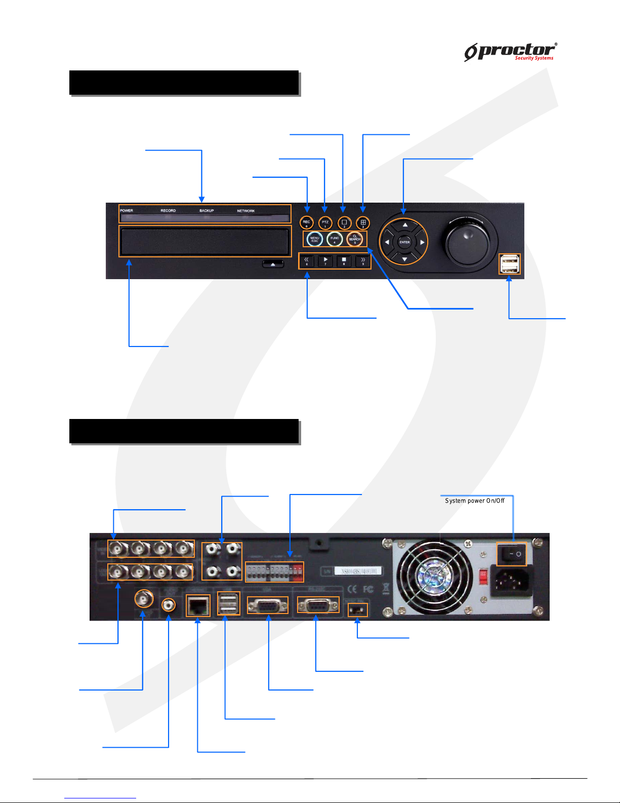
PRT 9004 (4ch)
FRONT CASE BUTTON Description
FRONT CASE BUTTON Description
Menu/Function/Search
Rec. button/ 0
Move button/ ENTER
USB Port:
2 PORT
USB port for using the
USB memory backup and
USD update
Record images
Move to menu & setup button/Operate PTZ camera
CD-ROM
Menu/ESC
Function / 4
Search / 5
LED Indicator
1 division(full screen) / 2
PTZ. button / 1
Button function
Operate Pan/Tilt camera
4 division / 3
Indicate present system status information
Power
System power On/Off
Audio input Alarm/Sensor/RS-485
Video output
Output video through
AV monitor
Audio Output
RS-232
Connect port for Program debugging.
VGA
Computer monitor (VGA) port
ETHERNET
LAN port
USB
USB memory backup and USB upgrade
REAR PANEL I/O Description
REAR PANEL I/O Description
Channel video Input
NTSC/PAL
Select NTSC or PAL mode
PRT 9004 (4ch)
Play backward / 6
Play / 7
Stop / 8
Play forward / 9
Loop out
Sys
te
m power On
/O
Page 14
Standalone DVR
User Manual Ver. 2.2
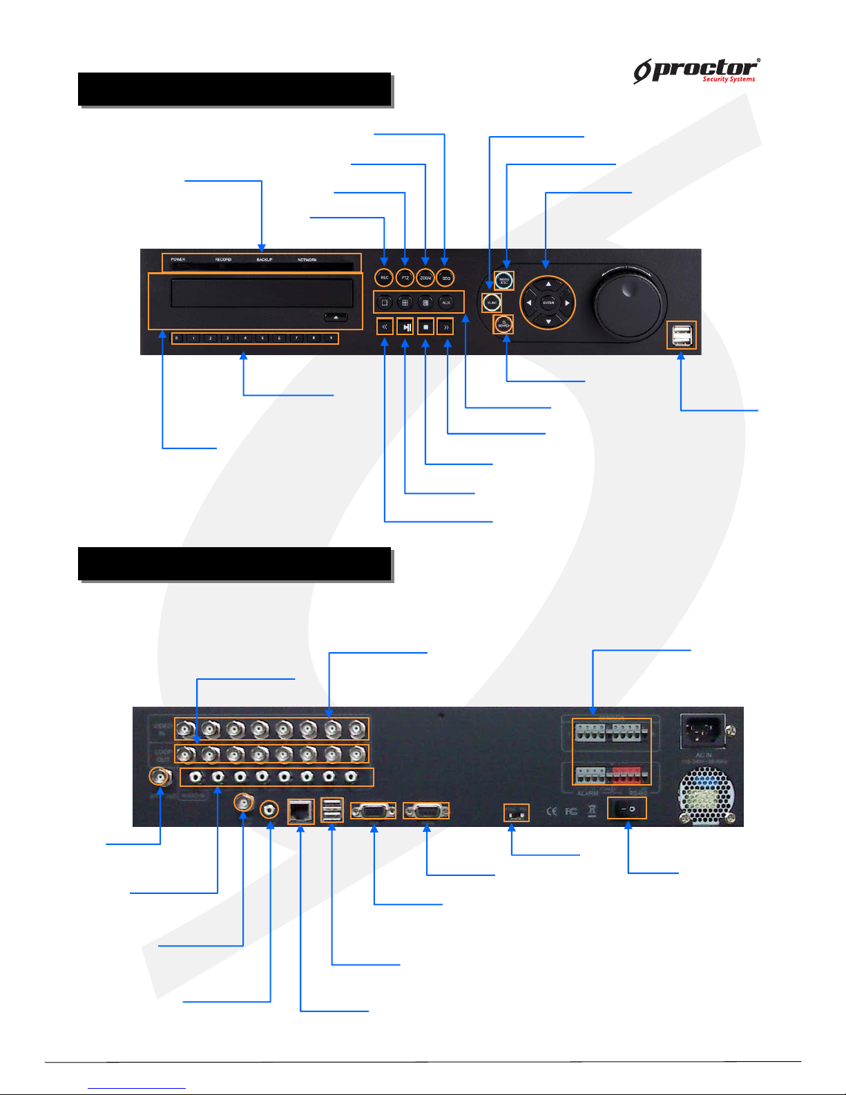
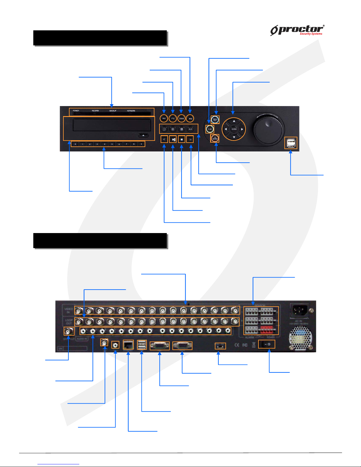
PRT 9008 (8ch)
FRONT CASE BUTTON Description
FRONT CASE BUTTON Description
Division button
Search button
Rec. button
Menu button
Move button
USB Port:
2 PORT
USB port for using the
USB memory backup and
USD update
Records images
Setup/Record/Search/Backup/OSD
Move to setup & /Operate PTZ camera
Number button
(0~9)
CD-ROM
Search saved data
LED Indicator
SEQ. button
Zoom button
PTZ. button
Play backward button
Stop button
Play forward button
Play forward on playback
Stop playback and converts to surveillance mode
Play backward on data playback
Division rotating surveillance button
Operate Pan/Tilt camera
PTZ/SPOT/Audio/Backup/Log view
Function button
Indicate present system status information
Play pause /play button
Play/Pause button
1ch,4ch,9ch,16ch division button
Power
System power On/Off
Camera video input
BNC 16 port
Audio Input
Alarm/Sensor/RS-485
Sensor(8port), Alarm(4Port)
RS-485 (2Port), GND(1Port)
SPOT Output
Video output
Output video through
AV monitor
Audio Output socket
RS-232
Connect port for Program debugging
VGA
Computer monitor (VGA) port
ETHERNET
LAN port
USB
USB memory backup and USB upgrade
REAR PANEL I/O Description
REAR PANEL I/O Description
Channel video output
Channel video output(Loop-out)
(75Ω AUTO)
NTSC/PAL
Select NTSC or PAL mode
PRT 9008 (8ch)
Page 15
Standalone DVR
User Manual Ver. 2.2
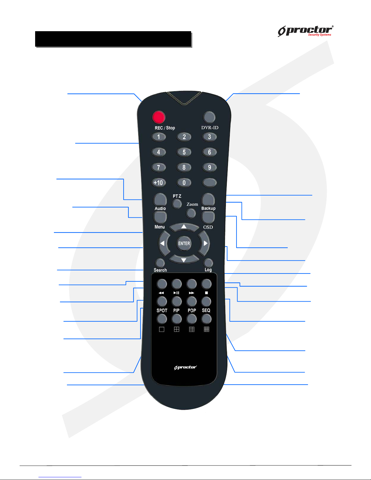
PRT 9016 (16ch)
FRONT CASE BUTTON Description
FRONT CASE BUTTON Description
Division button
Search button
Rec. button
Menu button
Move button
USB Port:
2 PORT
USB port for using the
USB memory backup and
USD update
Records images
Setup/Record/Search/Backup/OSD
Moves to setup & /Operates PTZ camera
Number buttons
(0~9)
CD-ROM
Search saved data
LED Indicator
SEQ. button
Zoom button
PTZ. button
Play backward button
Stop button
Play forward button
Play forward on playback
Stop playback and converts to surveillance mode
Play backward on data playback
Division rotating surveillance button
Operates Pan/Tilt camera
PTZ/SPOT/Audio/Backup/Log view
Function button
Indicate present system status information
Play pause /play button
Play/Pause button
1ch,4ch,9ch,16ch division button
Power
System power On/Off
Camera video input
BNC 16port
Audio Input
Alarm/Sensor/RS-485
Sensor(16port),
Alarm(4Port)
RS-485 (2Port), GND(1Port)
SPOT Output
Video Output
Output video through
AV monitor
Audio Output socket
RS-232
Connect port for Program debugging
VGA
Computer monitor (VGA) port
ETHERNET
LAN port
USB
USB memory backup and USB upgrade
REAR PANEL I/O Description
REAR PANEL I/O Description
Channel video output
Channel video output(Loop-out)
(75Ω AUTO)
NTSC/PAL
Select NTSC or PAL mode
PRT 9016 (16ch)
Page 16
Standalone DVR
User Manual Ver. 2.2
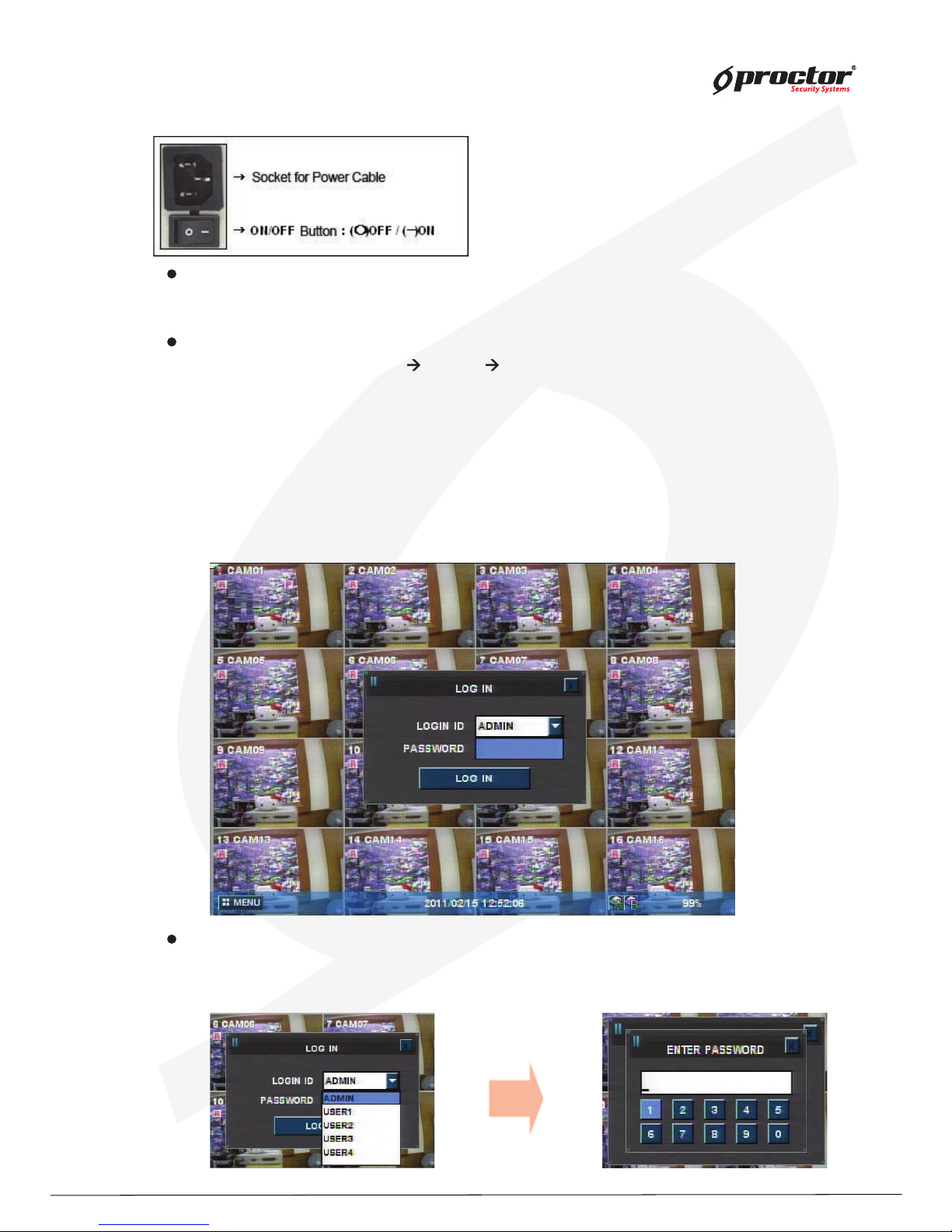
Remote Controller Button Description
Remote Controller Button Description
25) 16ch division button
1) Rec/Stop button
Records/stop images
2) DIV-ID button
Set DVR-ID
3) Numeric buttons
Applies setup details
and select channel
5) Menu button
Shows the menu. Moves
to upper menus and
complete setup
4) Audio button
Generates audio
through speaker
6) P/T button
Operates Pan/Tilt camera
7) Z/F button
Operates Zoom/Focus camera
8) Backup button
Backup saved images to
backup media
9 Division rotating surveillance button
1 division or 4 division rotating surveillance
10) Move button
Moves to setup and menu.
Operates PTZ camera.
11) Enter button
Inputs setup value.
12) Search button
Searches saved data
13) Log button
Shows DVR system logs
14) Play backward button
Max. x 128 play backward .
15) Pause button
Pause / playback the image
17) Stop button
Stops playback and converts to surveillance mode
16) Play forward button
Max. x 128 play forward.
Frame by frame play forward on playback
19) PIP button
18) SPOT button
SPOT monitor setup
20) POP button
22) 1ch division button
23) 4ch division button
24) 9ch division button
P/T
Z/F
21) SEQ button
Page 17
Standalone DVR
12
Page:
User Manual Ver. 2.2
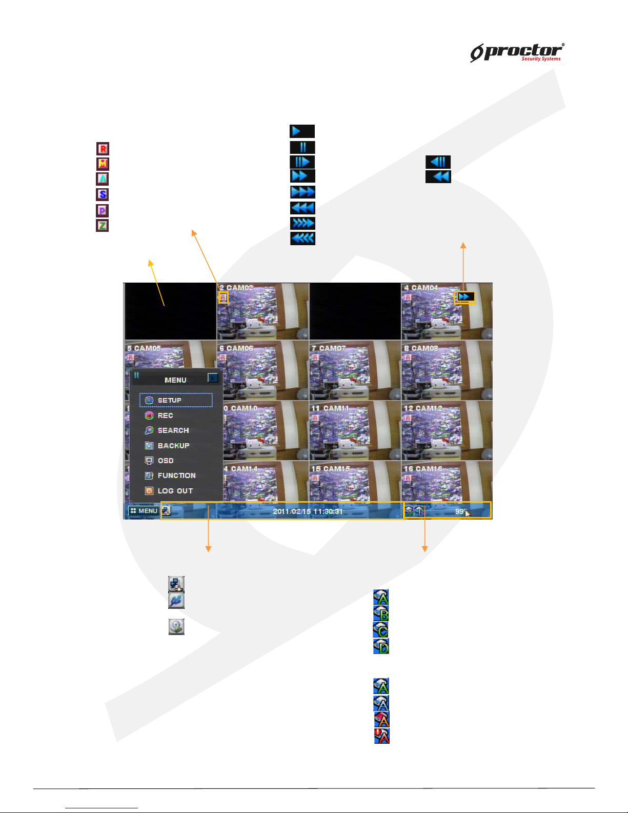
Power on/off
Power on
Press the power button at the back to be ‘ ON’ to turn it on after connecting the power cable.
* If you use this model with adapter, there is no power switch.
Power off
① press ‘ Menu’ button [ menu sy stem shutdown]
② select ‘ Shutdown’ and press ‘ ENTER/OK ’ button.
③ select ‘ ENTER/OK ’ button after the message “ system will shutdown” . Press ‘ENTER/OK ’
button.
④ press the power switch at the back to be ‘ Off’ .
Sy stem Log in
Input password
Input the password using number buttons at the password box .
☞
The default value is ‘0000’.
Page 18
Standalone DVR
13
Page:
User Manual Ver. 2.2
Screen display
[ Channel status ]
Channel number
Camera name
: Recording
: Motion detection in process
: Sensor detection in process
: Channel sequence indication
: PTZ indication
: Zoom button
[ Playback status ]
: Playback in progress
: Pause
: Playback per frame : Play backward per frame
: Speed playback : Speed play backward
: Double speed playback
: Double speed play backward
: Triple speed playback
: Triple speed play backward
[ HDD status ]
HDD indication
: hard disk#1
: hard disk#2
: hard disk#3
: hard disk#4
[ Status bar ]
: CMS connection status
: USB device connection status
Date & time
: Backup
* Coverted Channel
* color icon indications
Green : HDD installed & Active.
Blue : recording in progress
orange : Hard disk is full
red : Hard disk error
Page 19
Standalone DVR
14
Page:
User Manual Ver. 2.2
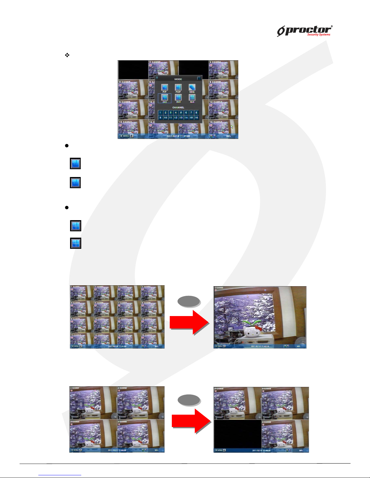
Full screen mode
- press this button.
- shifts to nex t channel each time you press this button.
Q uad screen mode
- press this button.
- shifts to the nex t channel each time you press this button.
- If you press a channel number button on remote- controller while
being displayed in the current q uad screen, the selected channel turns full screen.
MODE(Screen setup)
1
6
- If you press another channel number that is not being displayed in the current q uad screen, it turns
another q uad screen including the channel you selected.
CLICK right Mouse button(Only for 8 ch/1 6 ch product)
Page 20
Standalone DVR
15
Page:
User Manual Ver. 2.2
OSD button
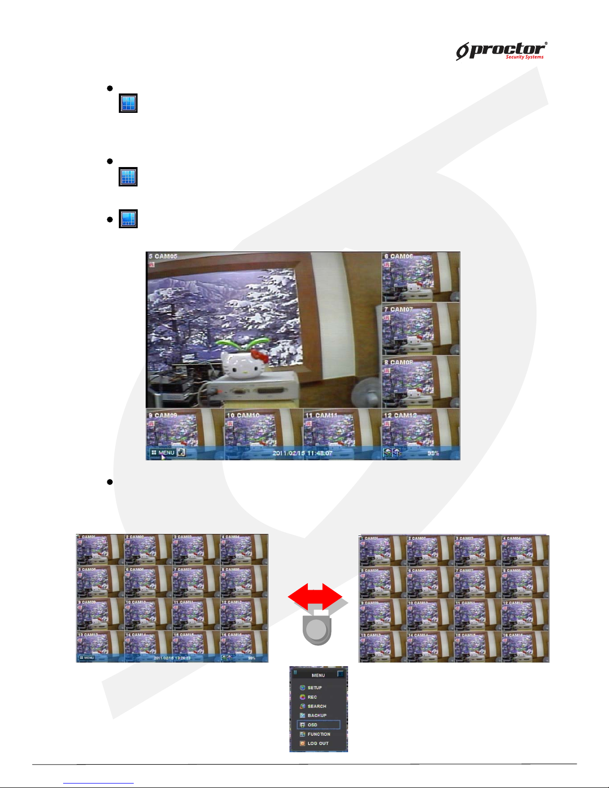
9 division screen mode
- press this button
16 division screen mode
- press this button
POP screen mode * only for 8Ch & 16Ch products
- press ‘ POP’ button, it will display a certain channel larger than other channels.
OSD mode
- press ‘ OSD’ button, icons and channel status phrases will appear or disappear.
OSD
Page 21
Standalone DVR
16
Page:
User Manual Ver. 2.2
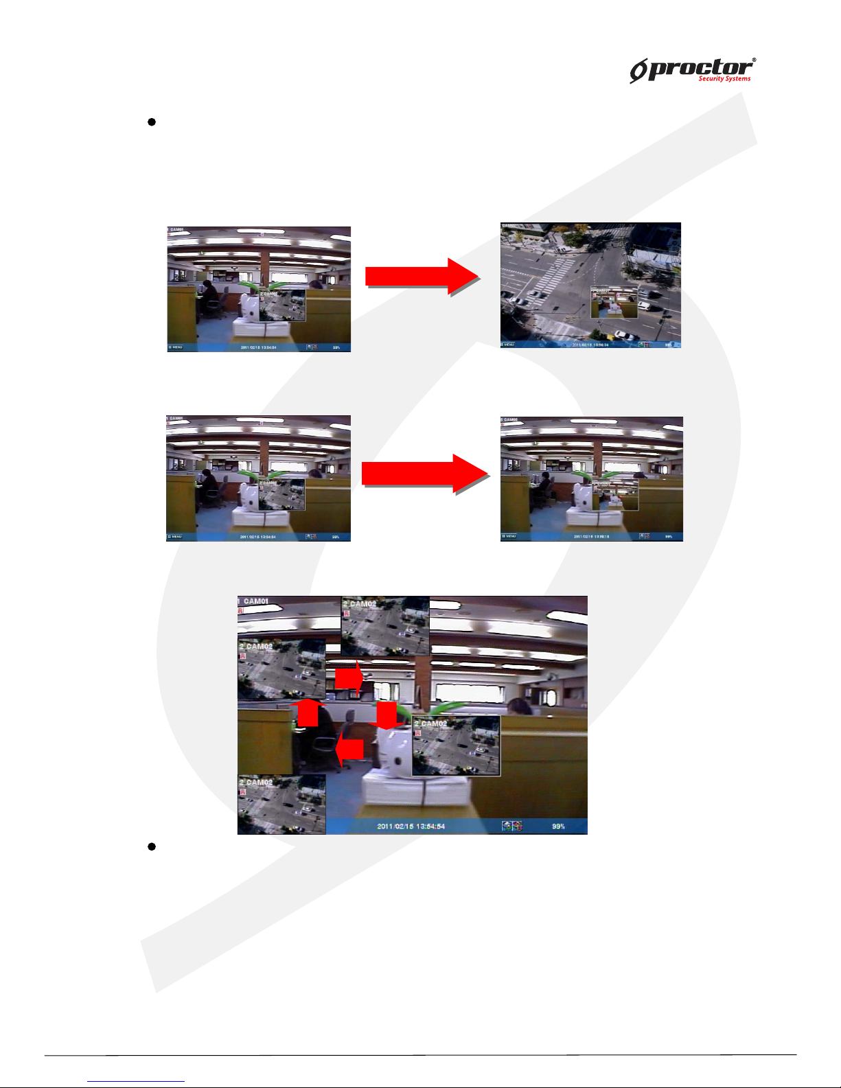
PIP screen mode
You can monitor 2 screens at the same time with small screen inside of one screen.
(1) press ‘PIP’ button on the remote control.
(2) press ‘PIP’ button one more time the display channels will be exchanged.
(3) If you press a channel number button on the controller, the channel will be displayed in
small screen.
Ex)
(4) you can move the small screen using arrow buttons.
Sequence playback screen mode
- If you press ‘SEQ’ button, full screen or quad screen will be displayed in sequence.
- you can setup duration time at system menu.
‘PIP’ Button
‘PIP’ Button
Cam ‘6’ Button
Cam ‘6’ Button
Page 22
Standalone DVR
17
Page:
User Manual Ver. 2.2
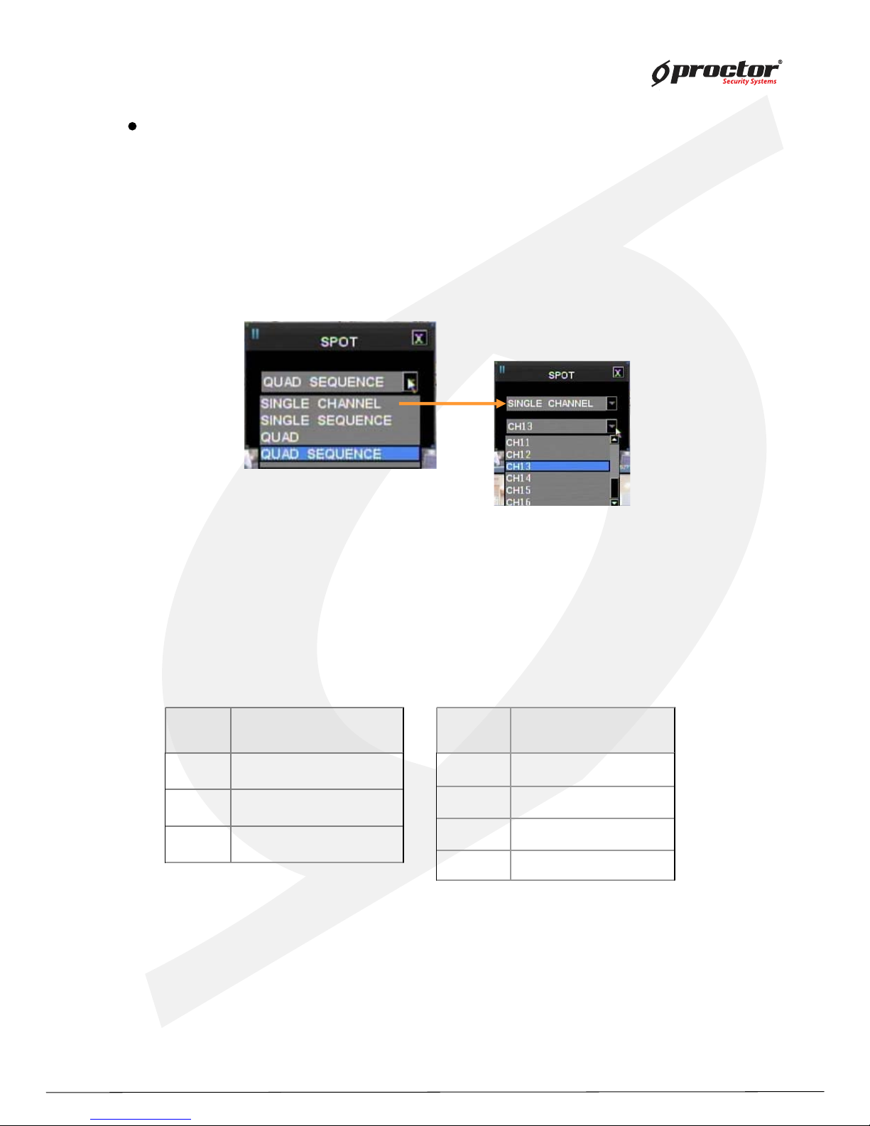
SPOT screen (This function is only for 8008 and 8016 DVR)
Display real time screen of another screen- mode in different monitor using ‘ SPOT OUT’ port
at the back of product.
Press ‘ Function’ button and select ‘ Spot’ to set up ‘ SPOT’ screen.
(1 ) type
① single channel
playback only one selected channel in full screen mode.
② seq uence single
playback each channel in full screen mode in seq uence.
you can setup duration time at system menu.
③ seq uence q uad
playback channels in q uad screen mode in seq uence.
[ 8008]
[ 8016]
you can setup duration time at system menu.
No. Camera
1 Camera 1 ~ Camera 4
2 Camera 5 ~ Camera 8
3 Camera 6 ~ Camera 9
Quad No. Camera
1 Camera 1 ~ Camera 4
2 Camera 5 ~ Camera 8
3 Camera 9 ~ Camera 12
4 Camera 13~ Camera 16
Page 23
Standalone DVR
18
Page:
User Manual Ver. 2.2
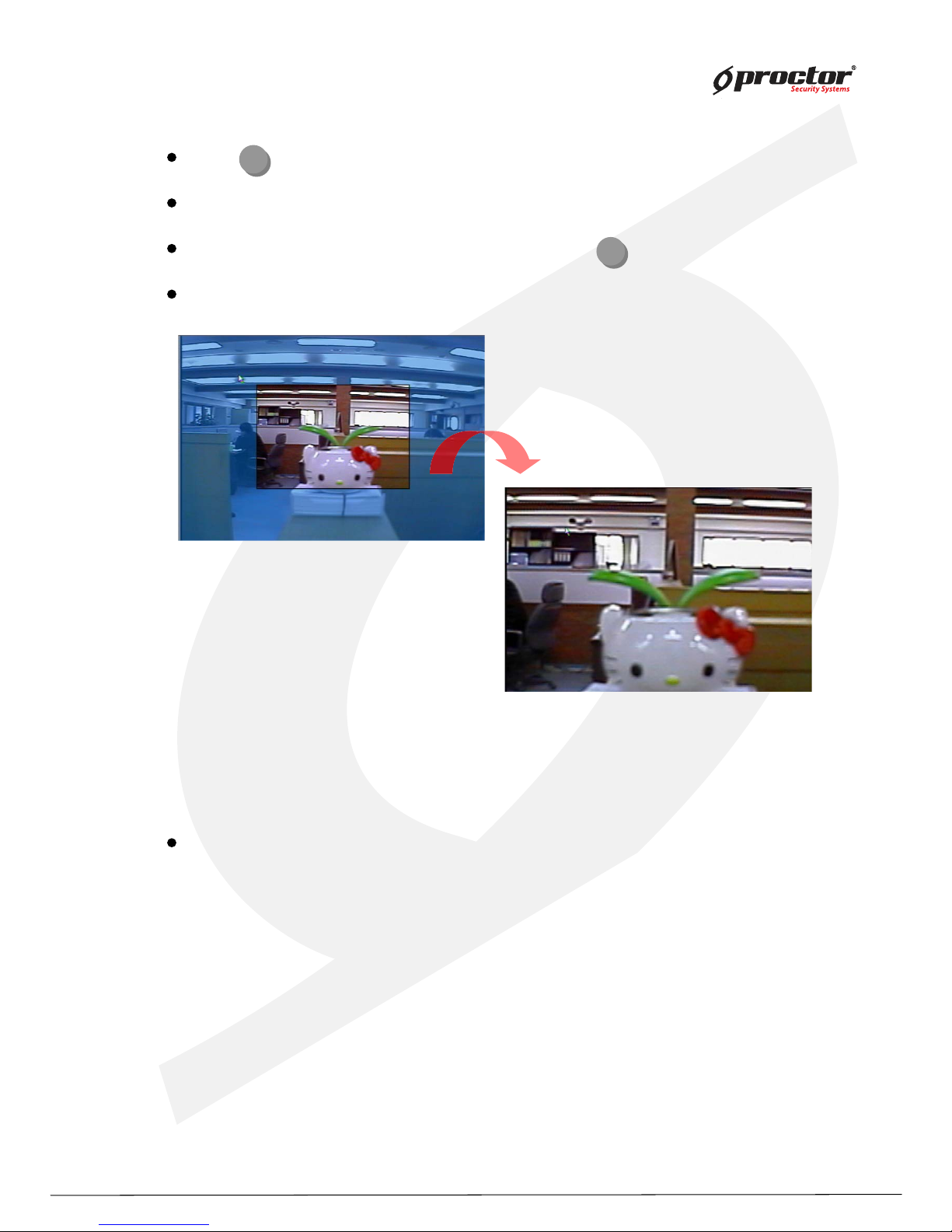
press (ZOOM) button in full screen mode to active digital z oom.
z oomed area moves as you press arrow buttons.
siz e of z oomed area gets bigger and smaller as you press (ZOOM ) button one more time.
press ‘ ENTER/OK ’ button, it shows the selected area bigger like the images below.
Dig ital z oom
Z/F
Z/F
Recording
press ‘ REC’ button to start recording.
Check before recording !!
(1 ) Check if hard disk is formatted.
(2) Check the camera output.
(3 ) Check if each channel names are correct.
(4 ) Set each channel’s recording q uality.
(5) Set each channel’ s recording frames.
Page 24
Standalone DVR
19
Page:
User Manual Ver. 2.2
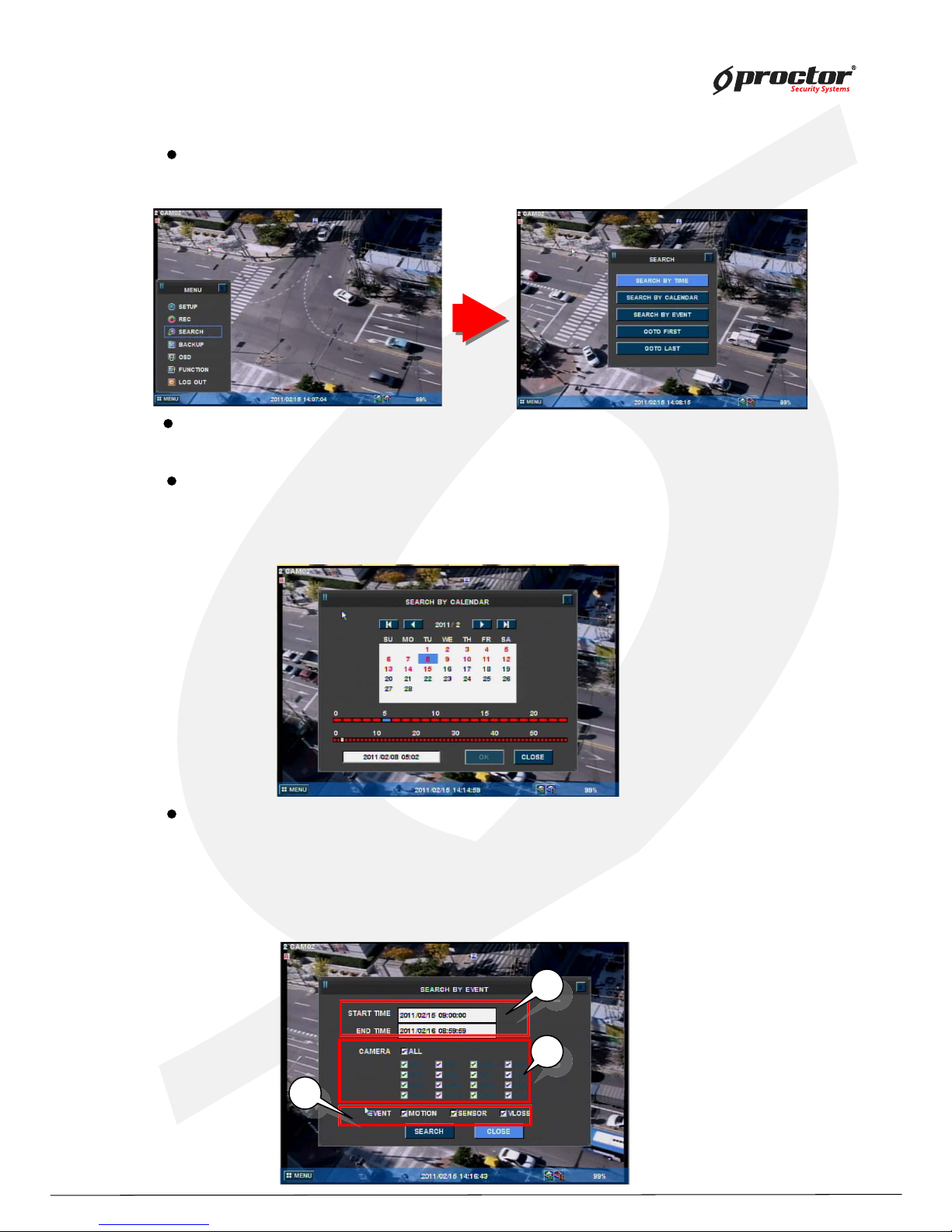
Search
Search by calendar
(1 ) you can see ‘ calendar’ menu like below if you select ‘ Search by calendar’ .
(2) select the date and time using arrow keys. Press ‘ ENTER/OK ’ button.
(3 ) lastly, select ‘ ENTER/OK ’ and press ‘ ENTER/OK button’ .
Search by time
(1 ) input the date and time to search. Press ‘ ENTER/OK ’ button.
Search by event
(1 ) you can see the menu like below if you select ‘Search by event’ .
(2) input the beginning date/time and ending date/time to search.
(3 ) select channels to search.
(4 ) select events to search.
(5) lastly, select search and press ‘ ENTER/OK ’ button.
2
2
2
3
3
3
4
4
press ‘ SEARCH’ button. Then y ou can see the ‘ Search’ menu lik e below.
Page 25
Standalone DVR
20
Page:
User Manual Ver. 2.2
Playback
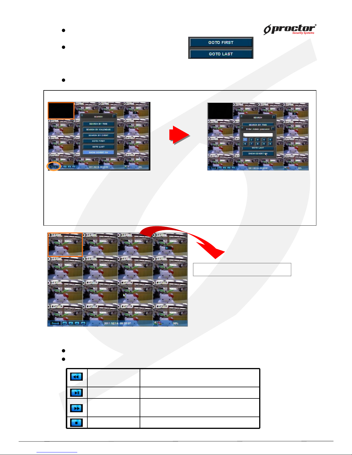
press ‘Playback’ button to start playback from the recent part of recording.
you can choose various playback screen modes by screen mode buttons.
◀◀
Rewind
Frame playback
- Rewind during playback.
- Playback by frame during pause.
▶ Playback Playback and pause the recorded screen.
▶▶
Fast forward
Frame playback
-Fast forward during playback.
-Playback by frame during pause.
■ stop Stop the playback.
0000
Go to first
playback from the beginning part of recorded.
Go to last
playback from the recent part of recorded.
How to view ‘Covert-on (Hidden)’ channel
Click this icon,
Or ‘Search’ button at the front panel.
Or ‘Search’ button in remote controller
Select ‘SHOW HIDDEN CH’.
Hidden channels will be displayed.
Page 26
Standalone DVR
21
Page:
User Manual Ver. 2.2
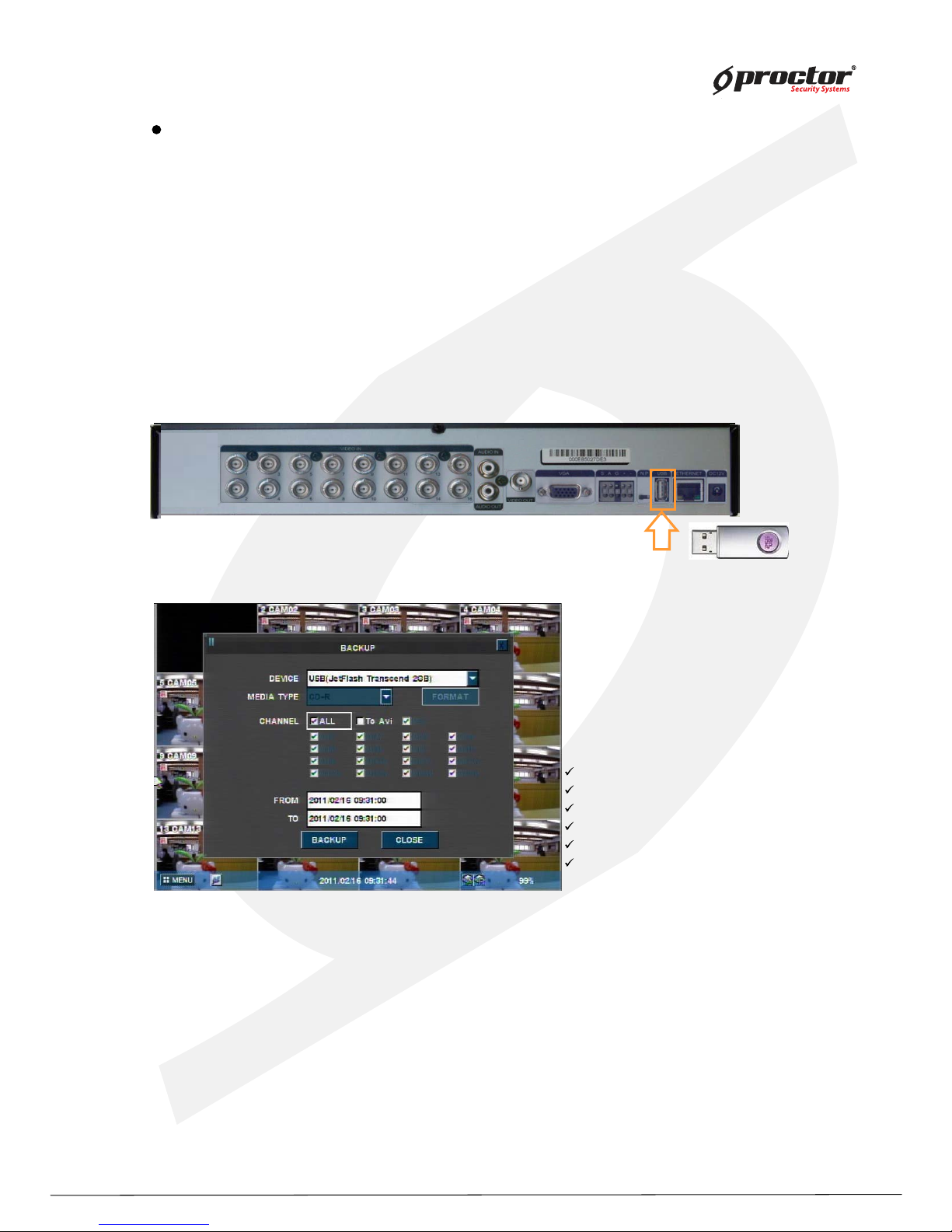
backup data using USB Memory stick.
(2) Press ‘Function’ button and select ‘Backup’
(3) Select options from menu.
DEVICE – select the device to backup.
MEDIA TYPE– select media ‘CD’,’DVD’ etc to backup.
FORMAT – format the media before backup.
CHANNEL – select channels to backup.
FROM – input the date/time to start backup.
TO – input the date/time to finish backup.
(4) Select ‘BACKUP’ and press ‘ENTER/OK’ button.
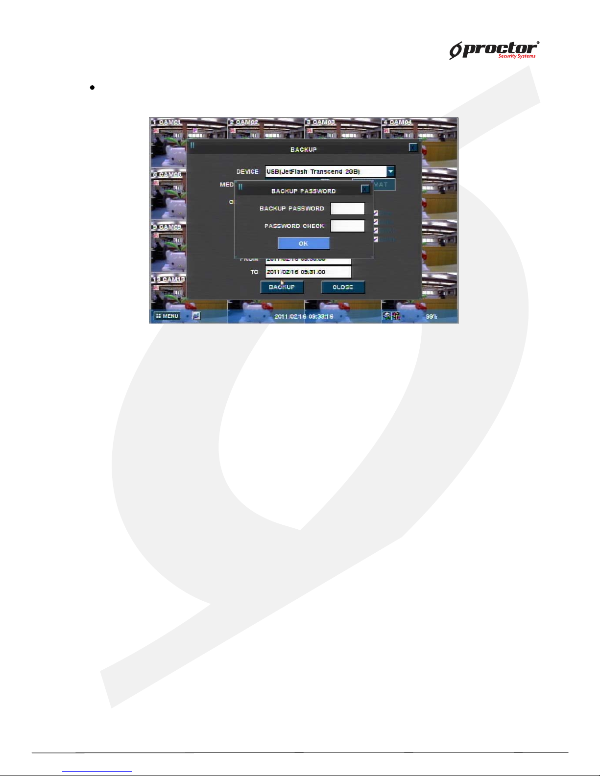
(5) Backup password window will show up and ask you to input the password. You must remember
this password, and you will be asked to input this password when you playback the data.
NOTE: 1) Both Admin and user can backup the data with this function. Admin can backup and
playback the hidden camera data, but user can’t access to backup the hidden camera data.
2) Backup password is not related with DVR passw
ord, you can input the virtual password
for backup only, and it must be 4 digit numbers.
3) This function is available from the DVR firmware version, 090427-q2g8 and BackupViewer
V1.0.9.420.
Backup data protection with virtual password
There are two ways to backup.
A. How to back up the original data for all or some channels .
Backup file can be run as a backup viewer in this way.
To back up, you should input a back up password.
B. AVI back up
AVI back up must useUSB memory. Also you can only back up for a single channel.
You can play for Window system on your PC as for AVI backed up file.
You do not have to input a back up password when you back up for AVI .
Note: When you play AVI backup dat
a, some the PC s need H.264 codec.
Page 27
Standalone DVR
22
Page:
User Manual Ver. 2.2
Note : If 20XX model, Data backup must be used USB memory stick and back panel’s USB port.
1) You can backup a hidden channel while logged in as an Admin.
2) If logged in as a general User, hidden channels cannot be backed up.
Page 28
Standalone DVR
23
Page:
User Manual Ver. 2.2
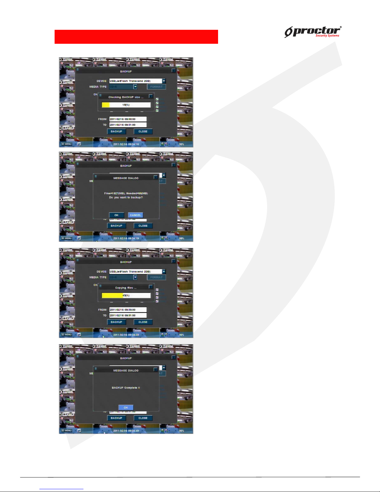
•NOTE: Do not remove USB device during Backup!.
• Checking backup file size
Note:
If back up size is small, you cannot view
progress rate.
2) File storage display
3) Copy files progress
4) Back up complete
Page 29
Standalone DVR
24
Page:
User Manual Ver. 2.2
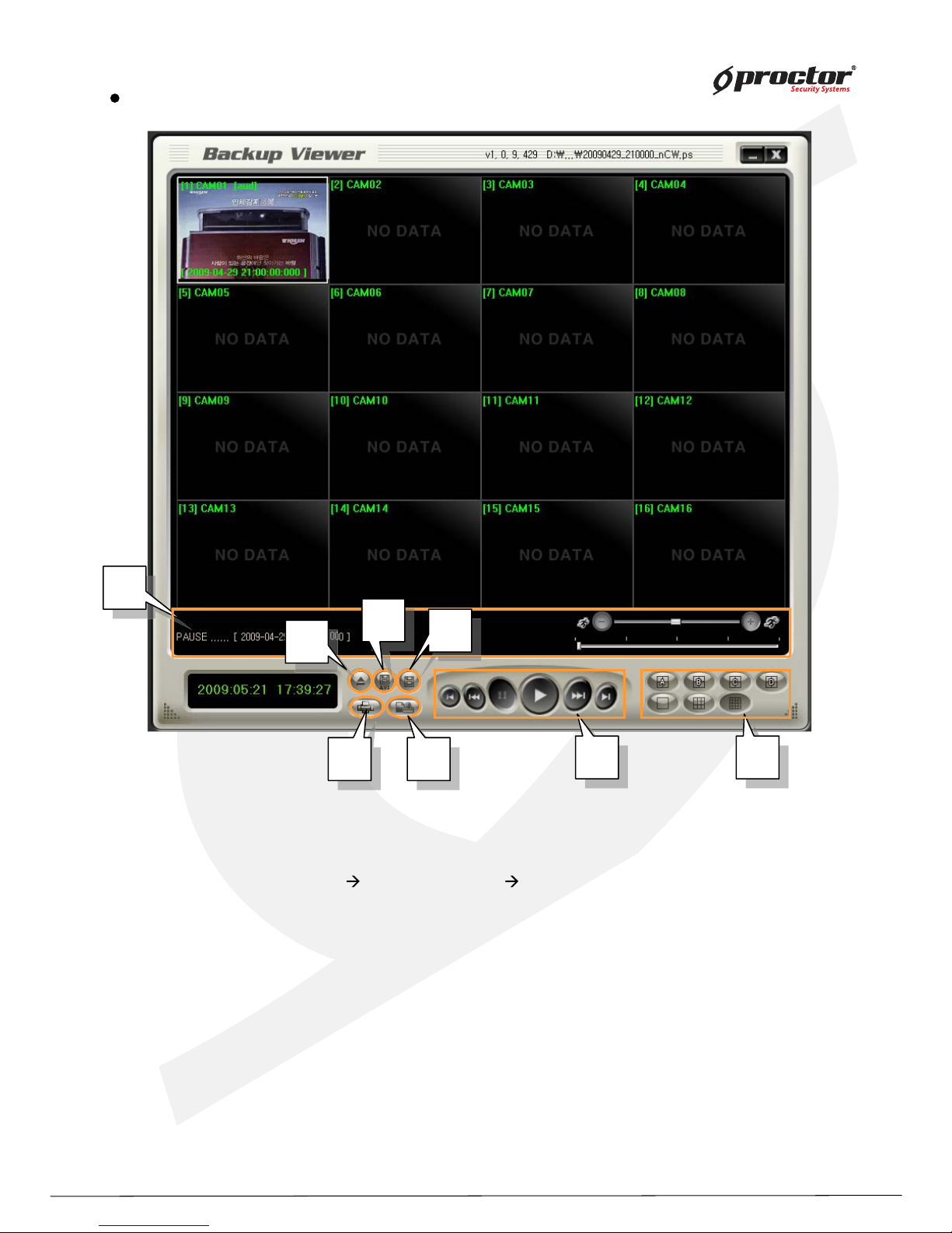
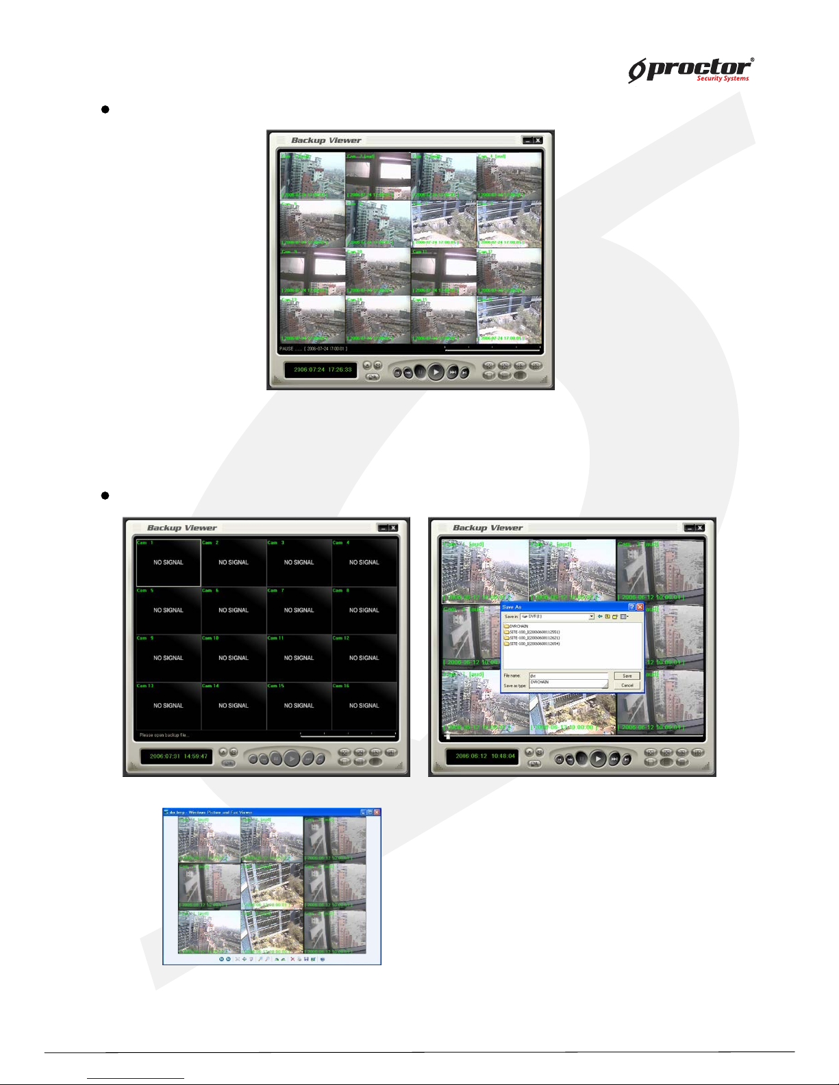
(1 ) Open file: Load the backup data.
(2) AVI: save the selected channel to avi during playback
Select channel
click this icon(start) click again(finish)
(3 ) Save: save the playback images as bmp file.
(4 ) Print screen image
(5) W atermark: check if there is any modification of data.
(6 ) Playback: playback the backup data. (playback, pause, speed playback, playback by
frame)
(7 ) Division: 1 division, 4 division, 9 division, 1 6 division
(8 ) Status box : display the status of backup viewer.
Back up viewer
8
8
8
6
6
6
7
7
7
4
4
4
4
5
5
5
3
3
3
1
1
2
2
Page 30
Standalone DVR
25
Page:
User Manual Ver. 2.2
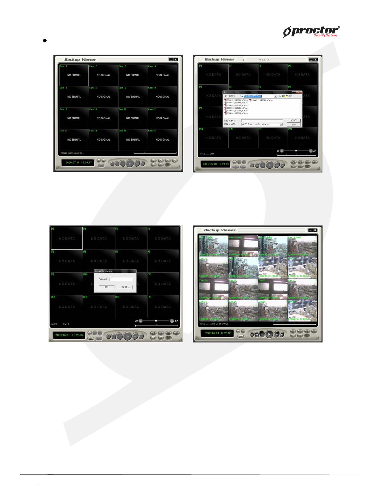
(1) Click ‘Open file’ button from the main screen.
(2) Select files to playback.
(3) Input
backup password
backup password
Open file
NOTE: 1) Both Admin and user can backup the data with this function. Admin can backup and
playback the hidden camera data, but user can’t access to backup the hidden camera data.
2) Backup password is not related with DVR password, you can input the virtual password
for backup only, and it must be 4 digit numbers.
3) This function is available from the DVR firmware version, 090427-q2g8 and BackupViewer
V1.0.9.420.
(4) After it completes to load the backup file, you can playback
it, and save it as bmp files.
Page 31
Standalone DVR
26
Page:
User Manual Ver. 2.2
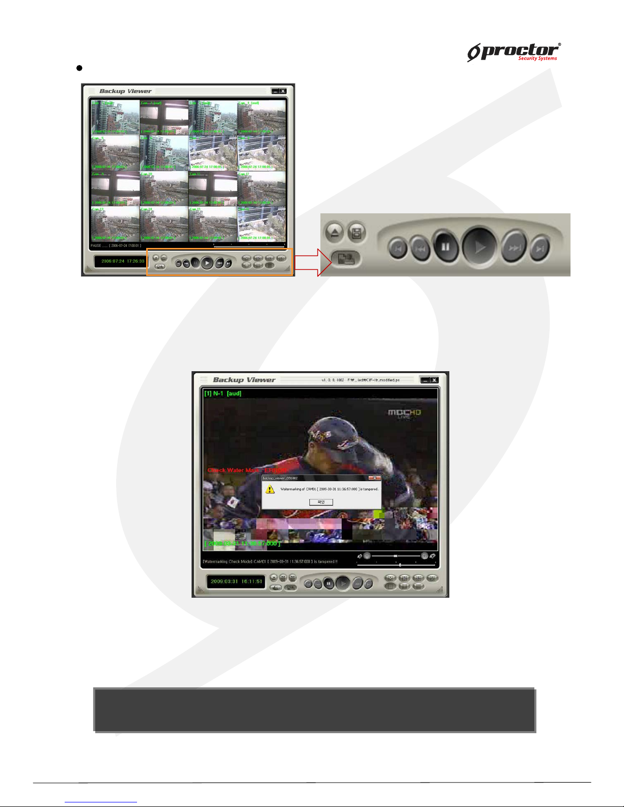
Save
(1) Save backup data.
(2) Select screen division.
(3) Click ‘save’ button.
(4) Name the ‘Bmp’ file and save.
Image of saved bmp file as 9 division screen
(1) Load files with audio data.
(2) Select and playback the channel, which audio is saved, it playbacks audio data at the same time.
Audio playback
Page 32
Standalone DVR
27
Page:
User Manual Ver. 2.2
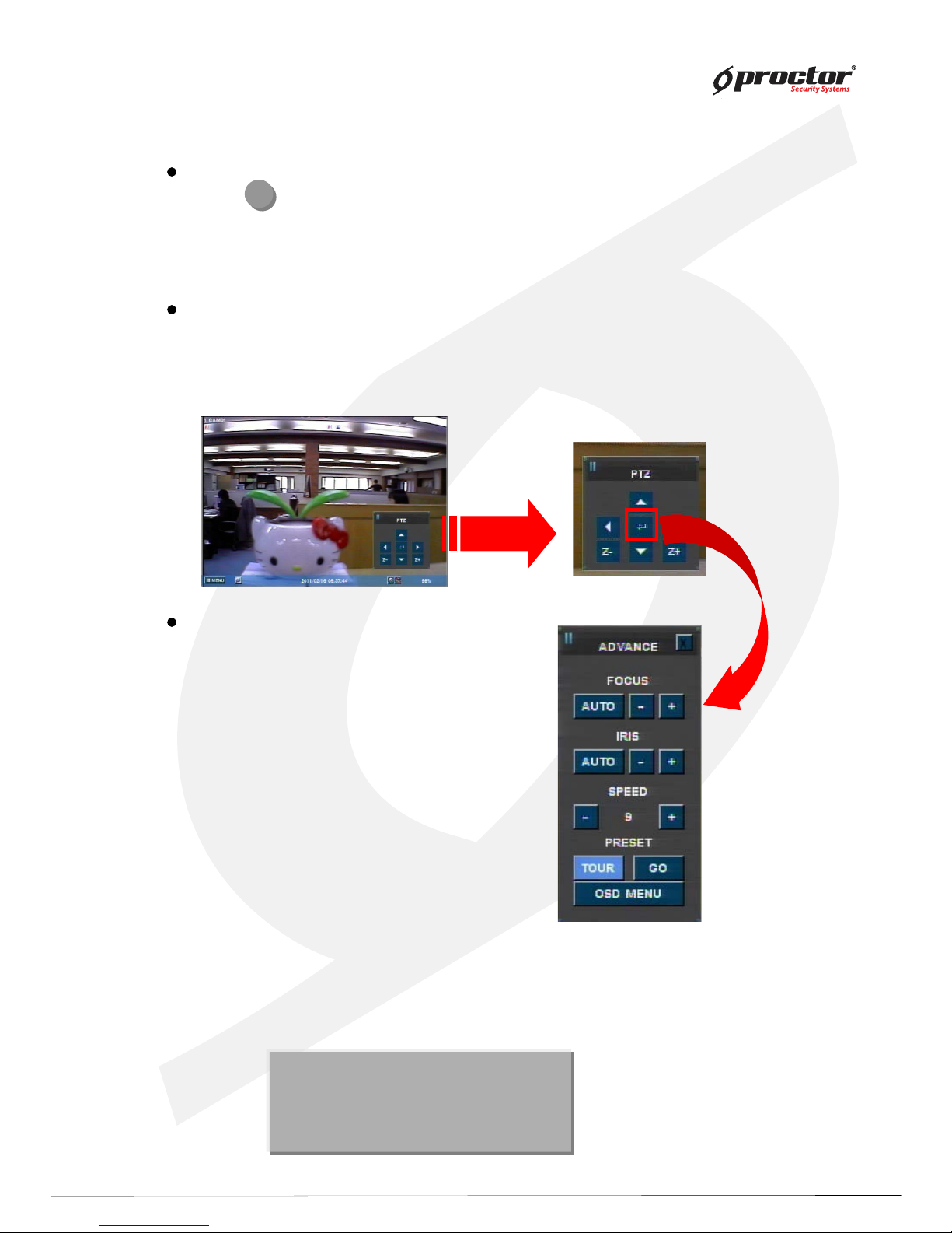
W atermark
(1 ) Load files to check watermarking
(2) Click ‘ watermark check’ button.
(3 ) Click playback or speed playback button.
(4 ) It shows the image with error message if there is any modification of data. It shows
‘ ENTER/OK ’ in the status box if there is no modification of data.
NOTE: If y ou play to recording file from watermark ing OFF,
y ou can view this messag e as above while the file header part and audio part are check ing .
So this messag e is not for modulation data.
NOTE: If y ou play to recording file from watermark ing OFF,
y ou can view this messag e as above while the file header part and audio part are check ing .
So this messag e is not for modulation data.
Page 33
Standalone DVR
28
Page:
User Manual Ver. 2.2
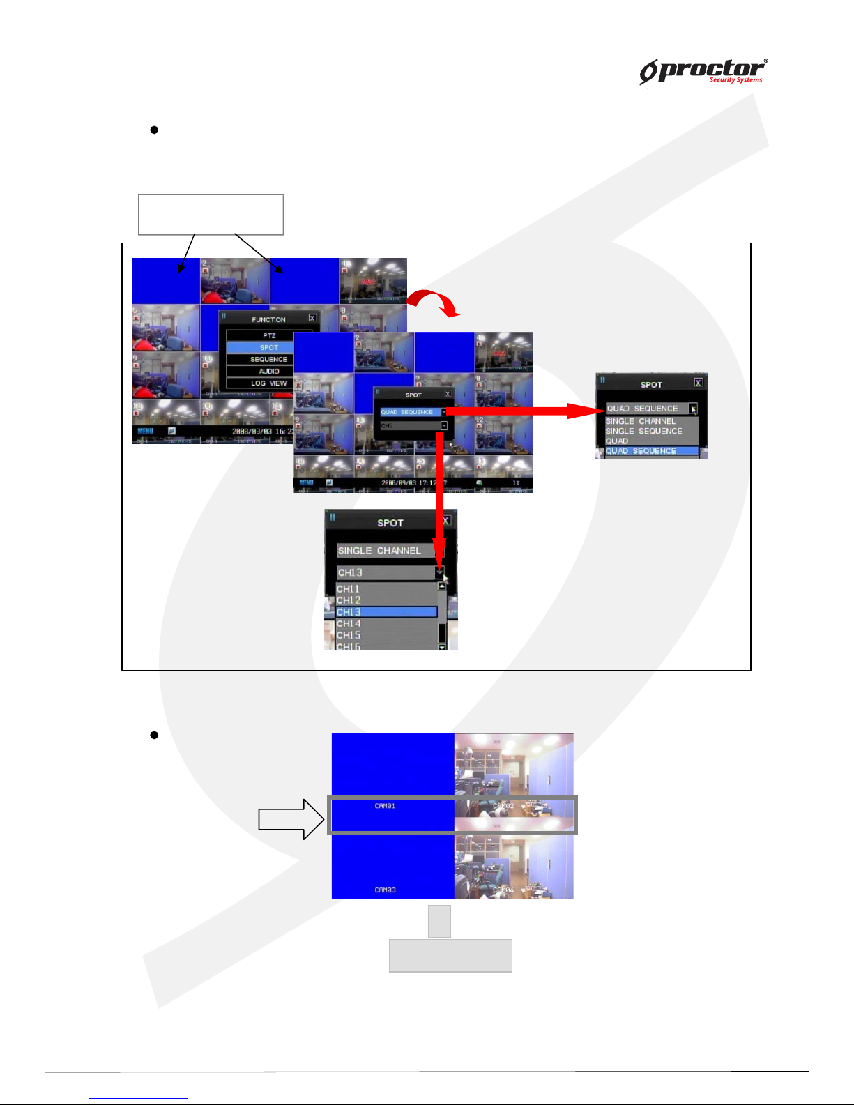
PTZ operation
Press button to display in full screen and you can operate PTZ cameras.
Press ‘ ENTER/OK ’ button in PTZ mode, you will see ‘ PTZ- ADVANC’ menu.
PTZ(FUNCTION)
PTZ
PTZ g eneral movement
(1 ) Moves pan/tilt camera from up/ down and right/ left using arrow keys.
(2) Enlarge or reduce the screen siz e by Z- /Z+ buttons while using z oom camera.
(3 ) Can move to other channels by number button on remote controller.
PTZ ADVANCE
(1 ) adj ust focus
① + : Focus in
② - : Focus out
③ AUTO : Auto focus mode
(2) Iris control
① + : Open iris
② - : Close iris
③ AUTO : Auto iris mode
(3 ) Operating speed
① + : Increase the speed.
② - : Decrease the speed.
(4 ) Preset
① Scanning
② Shortcut
NOTE: y ou can set ‘ Preset’ at Sy stem menu.
[ Menu → camer a s etup → preset]
y ou can set ‘ Scan list’ at S y stem menu.
[ Menu → camera setup → scan point]
NOTE: y ou can set ‘ Preset’ at Sy stem menu.
[ Menu → camer a setu p → preset]
y ou can set ‘ Scan list’ at S y stem menu.
[ Menu → camera setup → scan point]
Page 34
Standalone DVR
29
Page:
User Manual Ver. 2.2
SPOT(FUNCTION)
COVERT -ON
SCREEN
COVERT-ON
NO IMAGE IS
SHOW N
Note: Refer to pag e 30 in ‘ User Manual’ to select Spot out channels.
* Screen display setup – spot seq uence scanning (full screen)
* Screen display setup – spot seq uence scanning (q uad screen)
SPOT OUT DISPLAY
SPOT Operation(SPOT function only supports for 8008/8016 )
Select “ SPOT” after clicking “ FUNCTION” on DVR system .
Page 35
Standalone DVR
30
Page:
User Manual Ver. 2.2
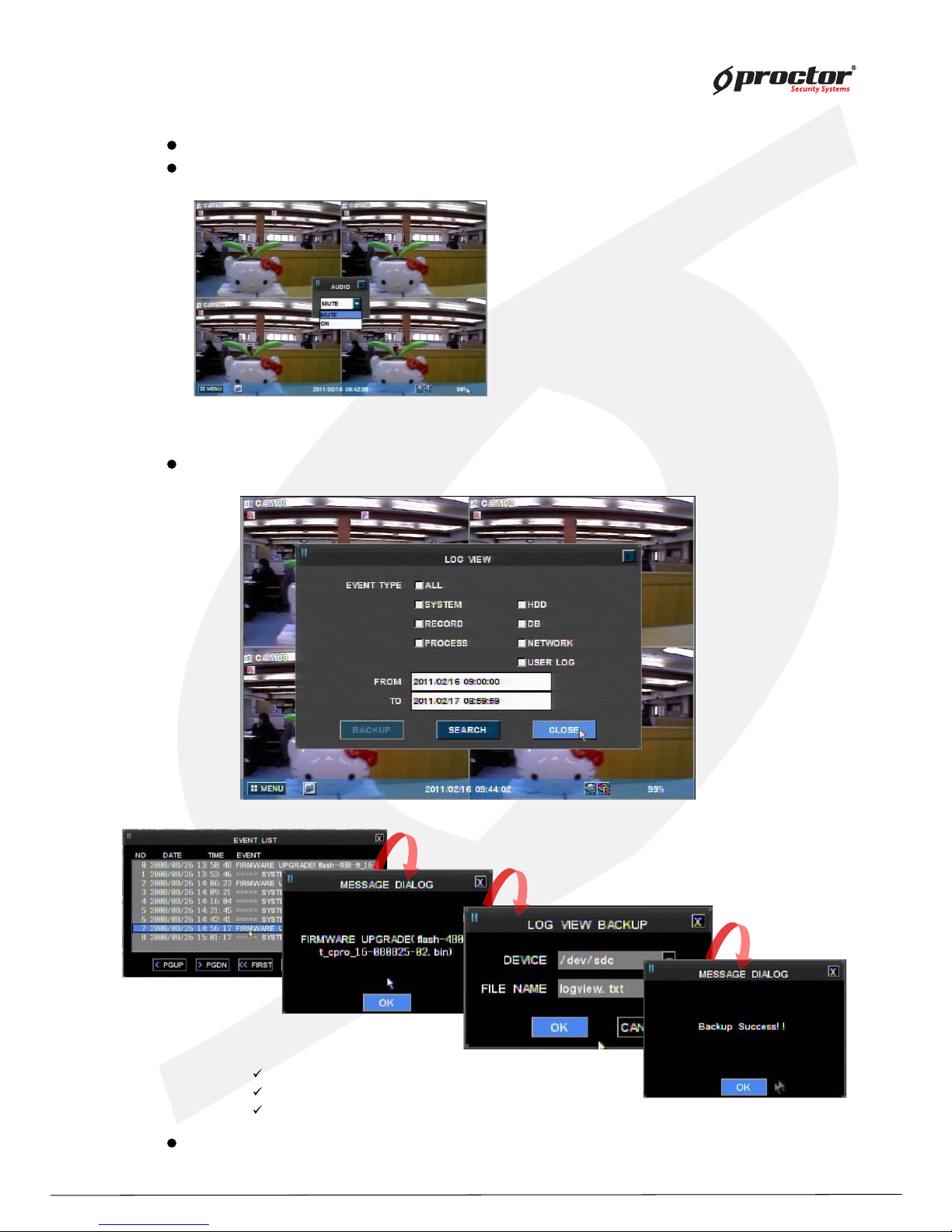
Audio(FUNCTION)
ON : Turn on audio
MUTE : Turn off audio
Log View(FUNCTION)
event type – select types of event to search
from – input date/time to start searching
to – input date/time to finish searc hin g
select ‘ Search’ and press ‘ ENTER/OK ’ button to start log search.
Turn on/ off audio.
Y ou can only playback audio in full screen mode.
search the system event log.
Page 36
Standalone DVR
31
Page:
User Manual Ver. 2.2
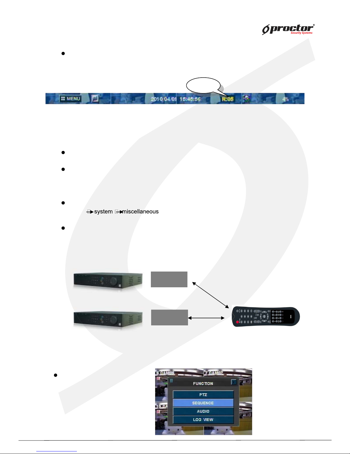
Remote – controller ID
DVR ID
DVR ID
Remote-controller ID
(1 ) can use to operate several DVRs at one site with one remote- controller.
(2) can operate a certain DVR ac c ording to the registered ID value.
R:01
R:02
Not work ing
work ing
Remote-controller ID : 02
SEQ UENCE(FUNCTION)
It will turn yellow if remote controller’ s ID matches with DVR ID. Then you can operate the DVR.
It will turn red if remote controller’ s ID does not match with DVR ID. Then you cannot operate
the DVR.
you can set the DVR IDs at System menu.
[ menu
]
setting up remote- controller ID
(1 ) press ‘ DVR- ID’ button on the remote- control.
(2) it will beep. Then you can input ‘Remote- control ID’ .
(3 ) press the DVR- ID to operate using number buttons.
Show each channel seq uentially .
Page 37
Standalone DVR
32
Page:
User Manual Ver. 2.2
Chapter 4 System setup
Page 38
Standalone DVR
33
Page:
User Manual Ver. 2.2
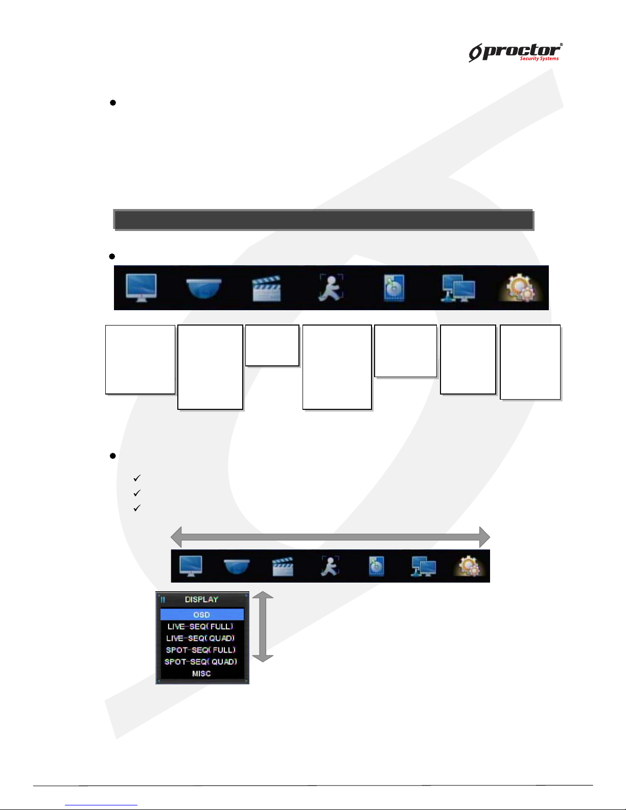
Before setting up sy stem
Starting sy stem menu
(1 ) press ‘ Menu’ button.
(2) input administrator’ s password in password box .
* Menu ty pe may vary different according to model.
NOTE: default value: 0000
NOTE: default value: 0000
Menu format
How to use Menu
DISPLAY CAMERA RECORD EVENT STORAGE NETW ORK SY STEM
you can move menu cursor using arrow buttons.
press ‘ ENTER/OK ’ button to activate the selected menu or to go to sub menu.
press ‘ Menu’ button to close system setup or go to the previous menu.
OSD
LIVE-SEQ (FULL)
LIVE-SEQ (Q UAD)
SPOT-SEQ (FULL)
SPOT-SEQ (Q UAD)
MISC
OSD
VE
SEQ
(FULL)
(Q UAD)
SPOT-SEQ (FULL)
SPOT-S
(Q UAD)
OSD
LIVE-SEQ (FULL)
LIVE-SEQ (Q UAD)
SPOT-SEQ (FULL)
SPOT-SEQ (Q UAD)
MISC
GENERAL
PRIVATE ZONE
PTZ
PRESET
TOUR
COLOUR
POSITION
GENERAL
TOUR
C
OLO
GENERAL
PRIVATE ZONE
PTZ
PRESET
TOUR
COLOUR
POSITION
PROPERTY
SCHEDULE
MISC
S
CH
PROPERTY
SCHEDULE
MISC
MOTION
SENSOR
VLOSS
E-MAIL
E-Mai, schedule
Alarm Schedule
MISC
SENSOR
VLOSS
Alarm Schedule
MOTION
SENSOR
VLOSS
E-MAIL
E-Mai, schedule
Alarm Schedule
MISC
SETUP
STREAM
DDNS
CLIENT
ACCESSLIST
SERVER
SETUP
STREAM
CLIENT
CC
SERVER
SETUP
STREAM
DDNS
CLIENT
ACCESSLIST
SERVER
CONFIG
TIME
SOFTW ARE
MISC
USER
SHUTDOW N
CONFIG
TIME
SOF
TW ARE
SHUTDOW N
CONFIG
TIME
SOFTW ARE
MISC
USER
SHUTDOW N
HDD FORMAT
HDD SMART
AUTO-BACK UP
MISC
AUTO-BA
CK
HDD FORMAT
HDD SMART
AUTO-BACK UP
MISC
Page 39
Standalone DVR
34
Page:
User Manual Ver. 2.2
1 ~ 8 9 ~ 16
Ex)
Saving/Canceling menu setup
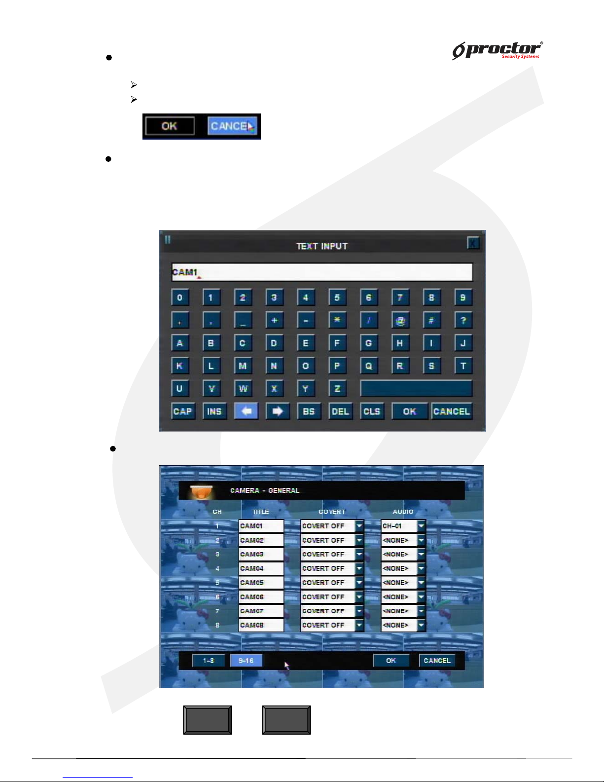
saving menu setup : select ‘ENTER/OK’’ button.
canceling menu setup : select ‘Cancel’’ or ‘Menu’ buttons.
Text input box
(1) select letters/symbols using arrow buttons.
(2) press ‘ENTER/OK’ button to select the letter/symbol.
(3) the selected letters/symbols will show on the top text box.
(4) click “CAP” to convert case – sensitive.
Moving to the next menu page
Press or button to move to the next menu page.
Page 40
Standalone DVR
35
Page:
User Manual Ver. 2.2
Setting up screen display
Left
margin
Bottom margin
Top margin
Right
margin
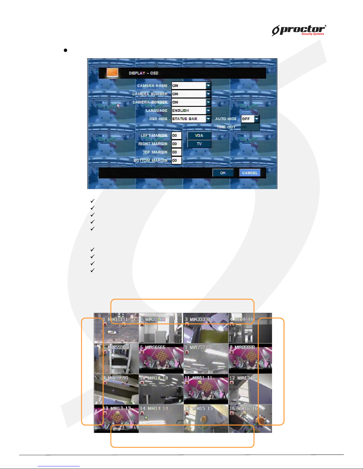
Screen display setup – On Screen Display
Camera name – Display each channel of camera name.
Camera number – Display channel number.
Camera border – Display each channel’s border.
Language – Choose menu language.
OSD HIDE – Turn on or off on OSD screen.
- ALL: All display
- STATUS BAR: status bar can be hidden after a certain time.
Left margin – Adjust the OSD’s left margin.
Right margin – Adjust the OSD’s right margin.
Top margin – Adjust the OSD’s top margin.
Bottom margin– Adjust the OSD’ bottom margin.
* VGA: VGA monitor margin setting, TV: TV output margin setting
Page 41
Standalone DVR
36
Page:
User Manual Ver. 2.2
Quad screen
number
camera
1 Camera 1 ~ Camera 4
2 Camera 5 ~ Camera 8
3 Camera 9 ~ Camera 12
4 Camera 13~ Camera 16
Quad screen
number
camera
1 Camera 1 ~ Camera 4
2 Camera 5 ~ Camera 8
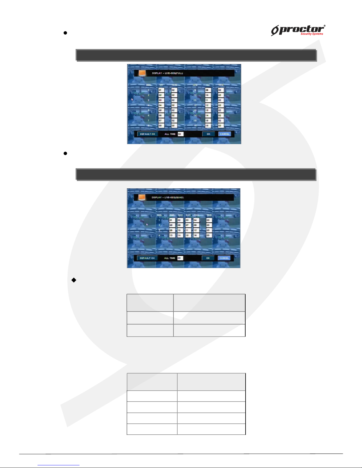
NOTE : can input max imum 99 second.
NOTE : can input max imum 99 second.
NOTE : can input max imum 99 second.
NOTE : can input max imum 99 second.
Screen display setup – live seq uence scanning (sing le screen)
Setup duration time for live seq uence scanning in full screen.
Screen display setup – live seq uence scanning (q uad screen)
Setup duration time for live seq uence scanning in q uad screen.
[ 8008]
[ 8016]
Default
Page 42
Standalone DVR
37
Page:
User Manual Ver. 2.2
NOTE : can input max imum 99 second.
NOTE : can input max imum 99 second.
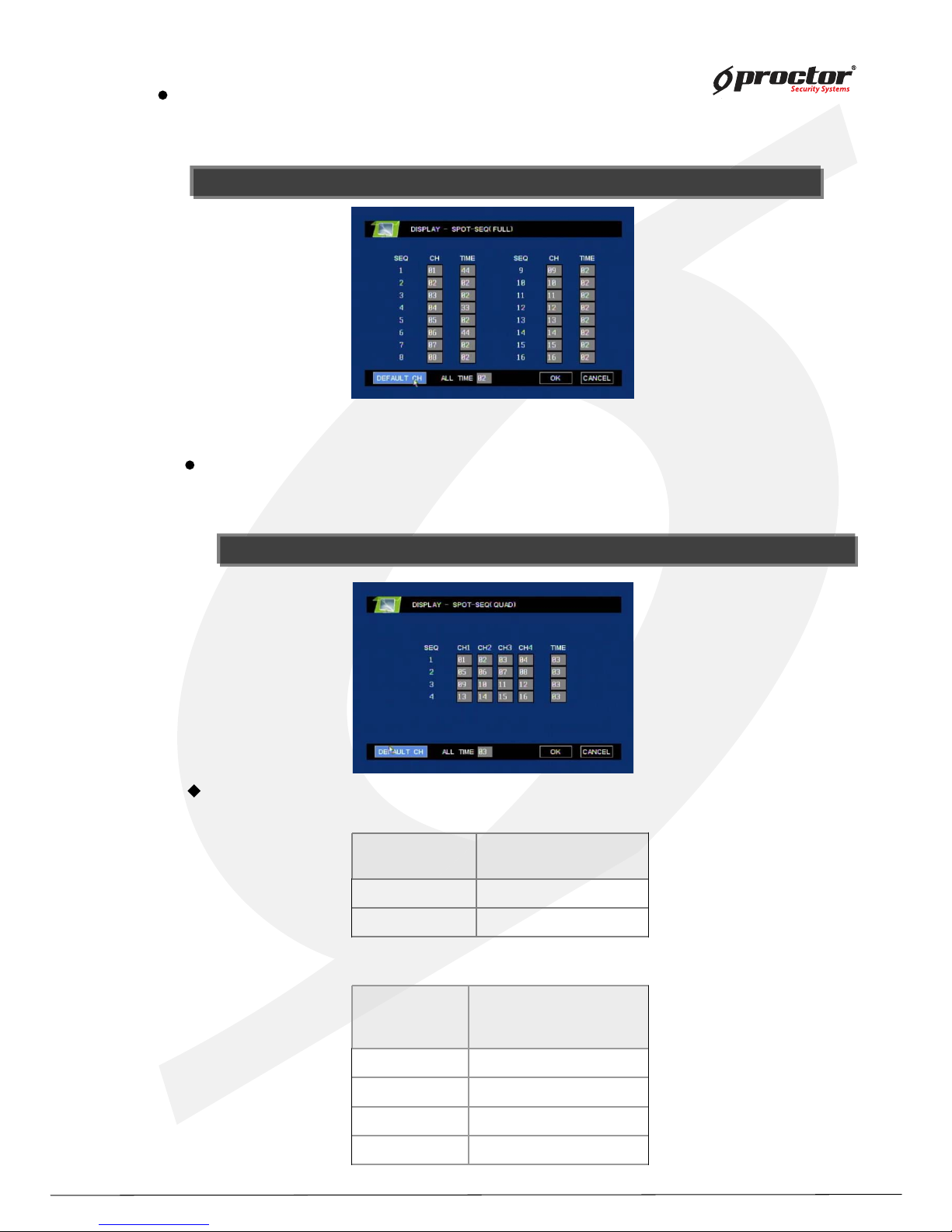
Screen display setup – spot seq uence scanning (full screen)
This function does not apply to some models.
Setup duration time for spot seq uence scanning in full screen.
Quad screen
numbe
r
camera
1 Camera 1 ~ Camera 4
2 Camera 5 ~ Camera 8
3 Camera 9 ~ Camera 12
4 Camera 13~ Camera 16
Quad screen
number
camera
1 Camera 1 ~ Camera 4
2 Camera 5 ~ Camera 8
NOTE : can input max imum 99 second.
NOTE : can input max imum 99 second.
Screen display setup – spot seq uence scanning (q uad screen)
This function does not apply to some models.
Setup duration time for spot seq uence scanning in q uad screen.
[
8008]
[ 8016]
[ Default]
Page 43
Standalone DVR
38
Page:
User Manual Ver. 2.2
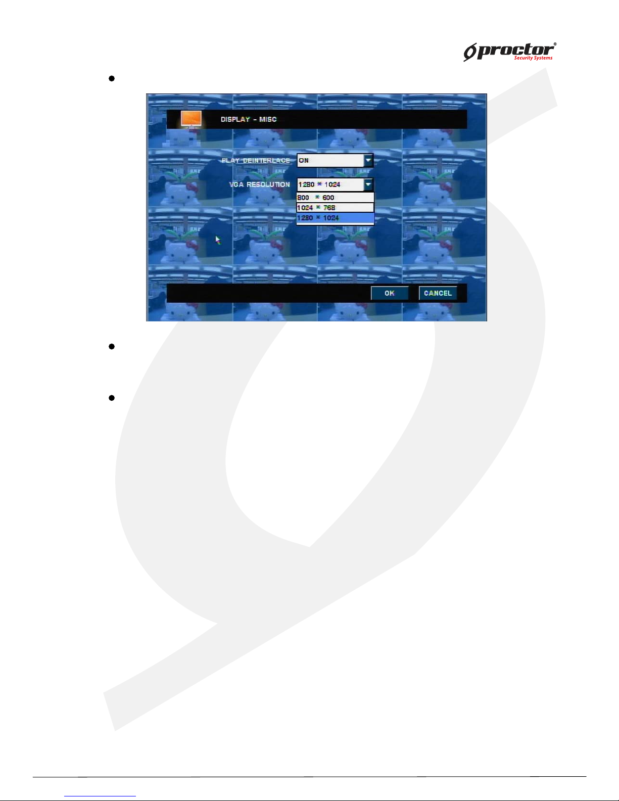
Screen display setup – miscellaneous
Deinterlace
prevent screen twittering during playback of image which is recorded in low frame
rate and 720X480 or 720X576 resolution.
VGA frequency
setup the frequency of connected VGA monitor.
- 800 * 600
- 1024 * 768
- 1280 * 1024
Page 44
Standalone DVR
39
Page:
User Manual Ver. 2.2
Camera Setup
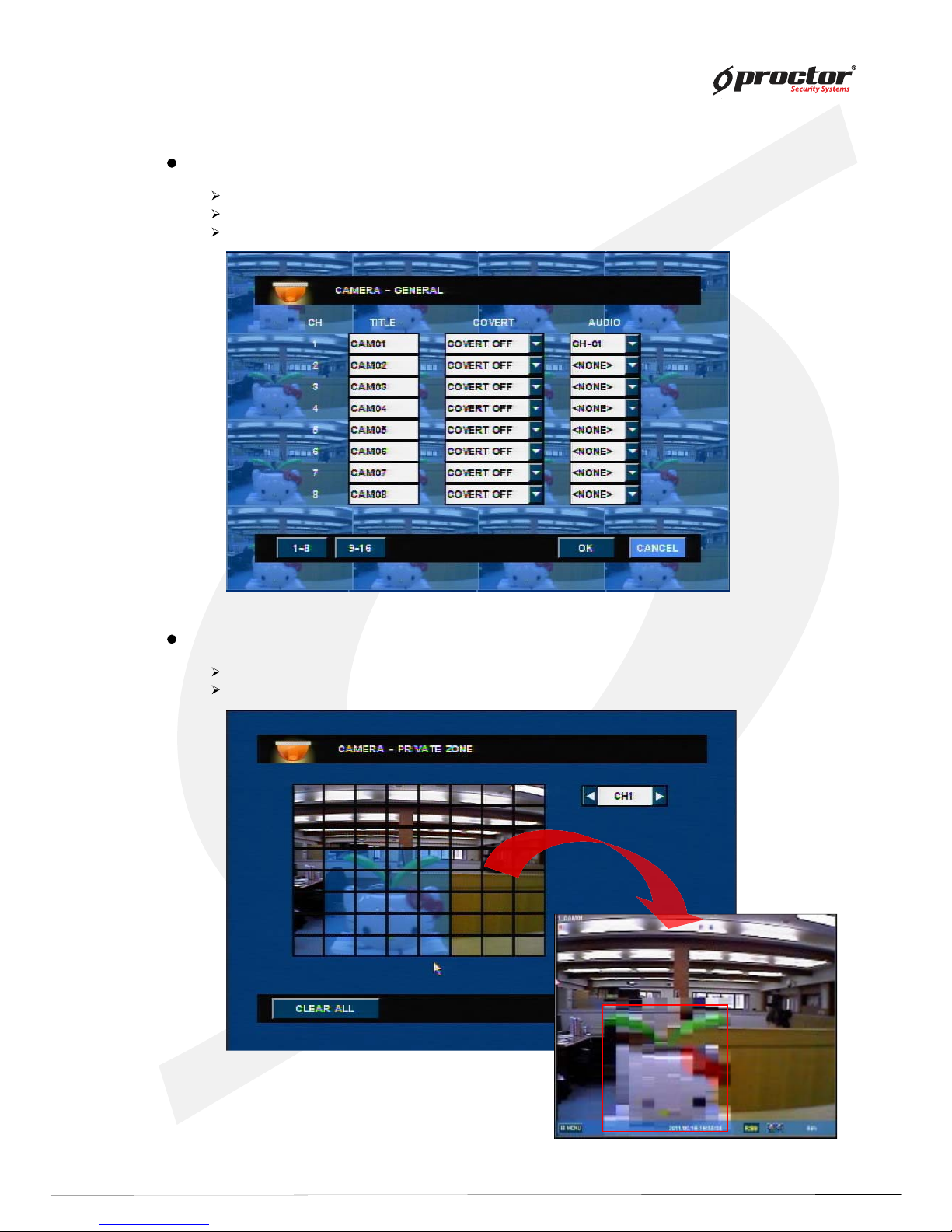
Camera setup – general
title – input channel names.
COVERT on/off – show or hide channels.
audio – select connected audi o channels.
Camera set up – PRIVATE ZONE
Zone set up – Censor the selected Cell z one.
Clear all – Clear the selected Cell z one.
The on- screen image will be censored as above picture.
Page 45
Standalone DVR
40
Page:
User Manual Ver. 2.2
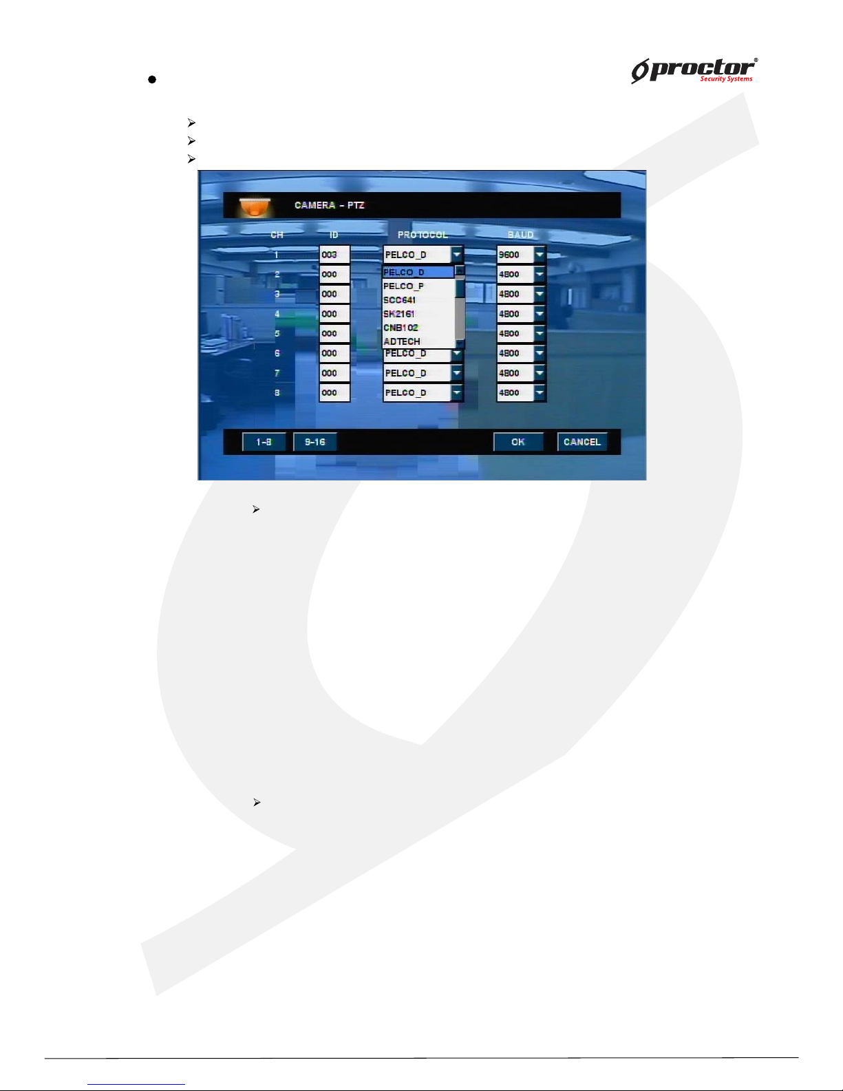
Camera setup – PTZ
ID – input camera IDs.
protocol – select the registered protocol.
baud – select the registered baud.
The supported protocol type’s DVR
- PELCO-D
- PELCO-P
- SCC641
- SK2161
- CNB102
- ADTECH
- 15-CD51M
- COP1
- COP2
- DSC230
- LININ
- CYNIX
- NITRO
- PTC-400C
- TeleEye
- TecVoz
Communication speed(bps)
- 1200
- 2400
- 4800
- 9600
- 19200
- 38400
- 115000
Page 46
Standalone DVR
4 1
Page:
User Manual Ver. 2.2
NOTE : sy stem will record according to preset positions of camera.
check if camera supports preset function before setting up.
can setup 64 preset positions for each channel.
NOTE : sy stem will record ac cor din g to preset positions of ca m er a.
check if camera supports preset function before setting up.
can setup 64 preset positions for each channel.
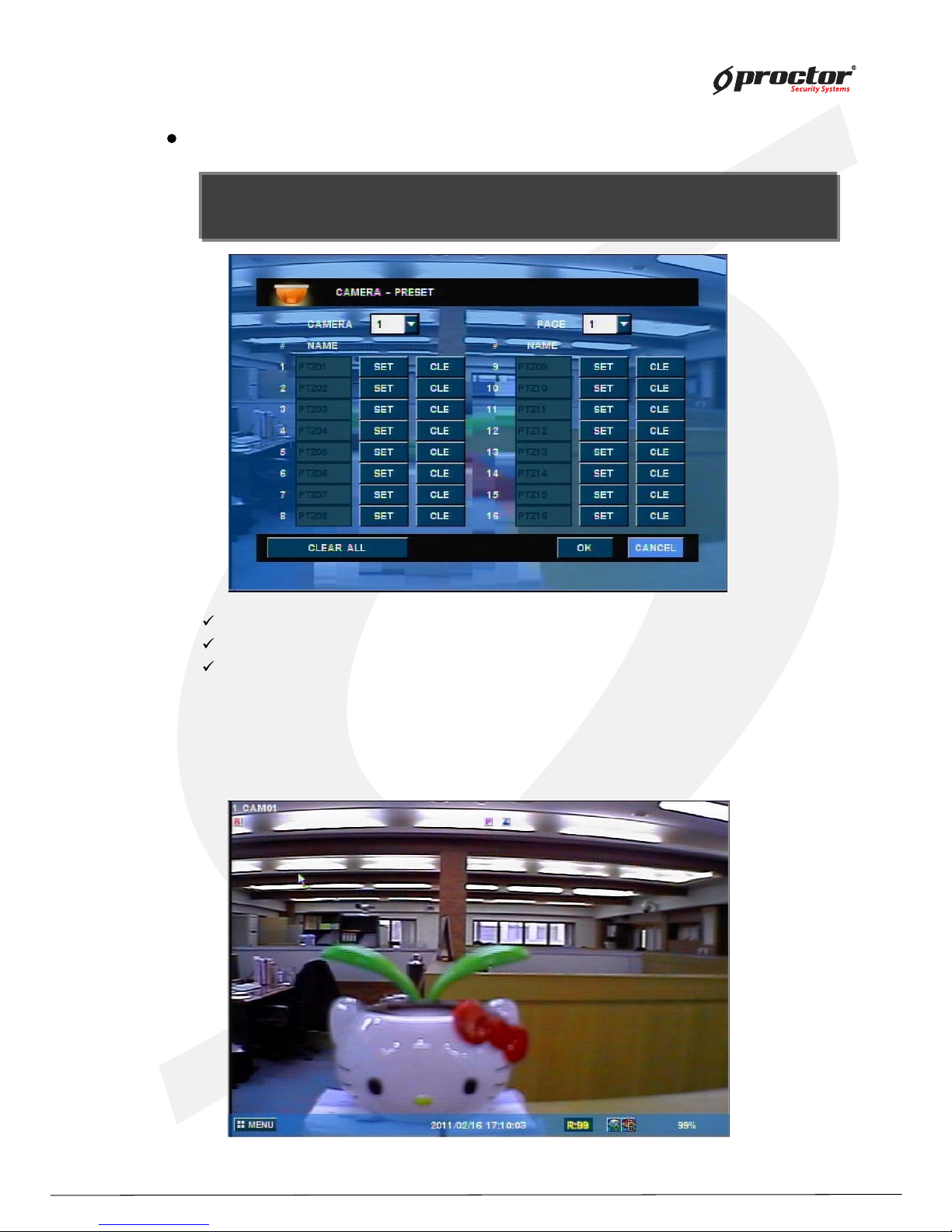
Camera setup – preset
(1 ) Select camera.
(2) Select ‘ Set’ button.
(3 ) Then the channel turns PTZ mode.
(4 ) Move the camera to get the position you want.
(5) Press ‘ ENTER/OK ’ button to save the preset.
camera – select cameras to setup preset positions.
page – move to the nex t page.
clear all – clear all the setup values.
Page 47
Standalone DVR
4 2
Page:
User Manual Ver. 2.2
Ex )
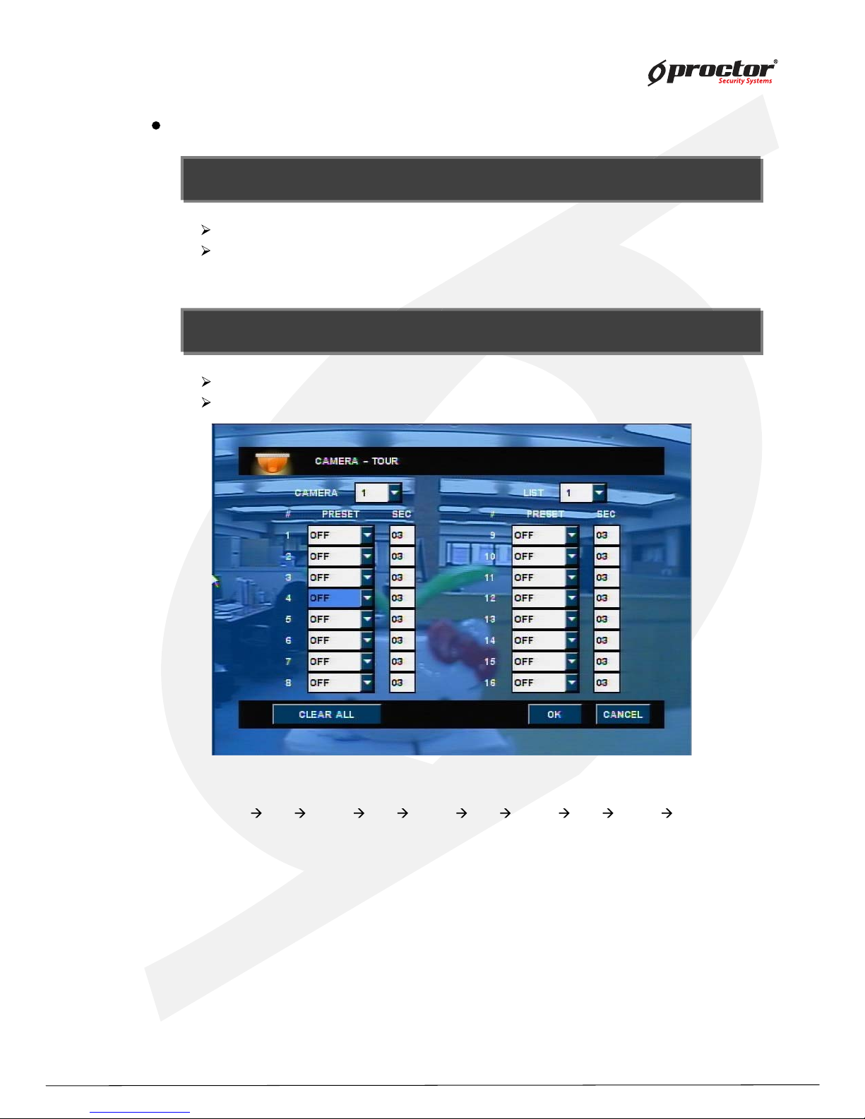
Camera 1 will move following the path as below.
PTZ0 1
3 sec PTZ0 9 3 sec PTZ0 4 3 sec PTZ1 5 3 sec PTZ0 1 ……. .
Camera setup – TOUR
NOTE : you can move camera t o follow the path by saved preset positions for each channel. Y ou can set 4
scan point list for each channel.
NOTE : you can move camera to follow the path by saved preset positions for each channel. Y ou can set 4
scan point list for each channel.
NOTE : you can setup total 4 lists.
one scan list is consist of total 1 6 preset position.
NOTE : you can setup total 4 lists.
one scan list is consist of total 1 6 preset position.
camera – select a camera to set scan point.
list – select a list to save scan point.
preset – select preset position you want.
clear all – clear all setup values.
Page 48
Standalone DVR
43
Page:
User Manual Ver. 2.2
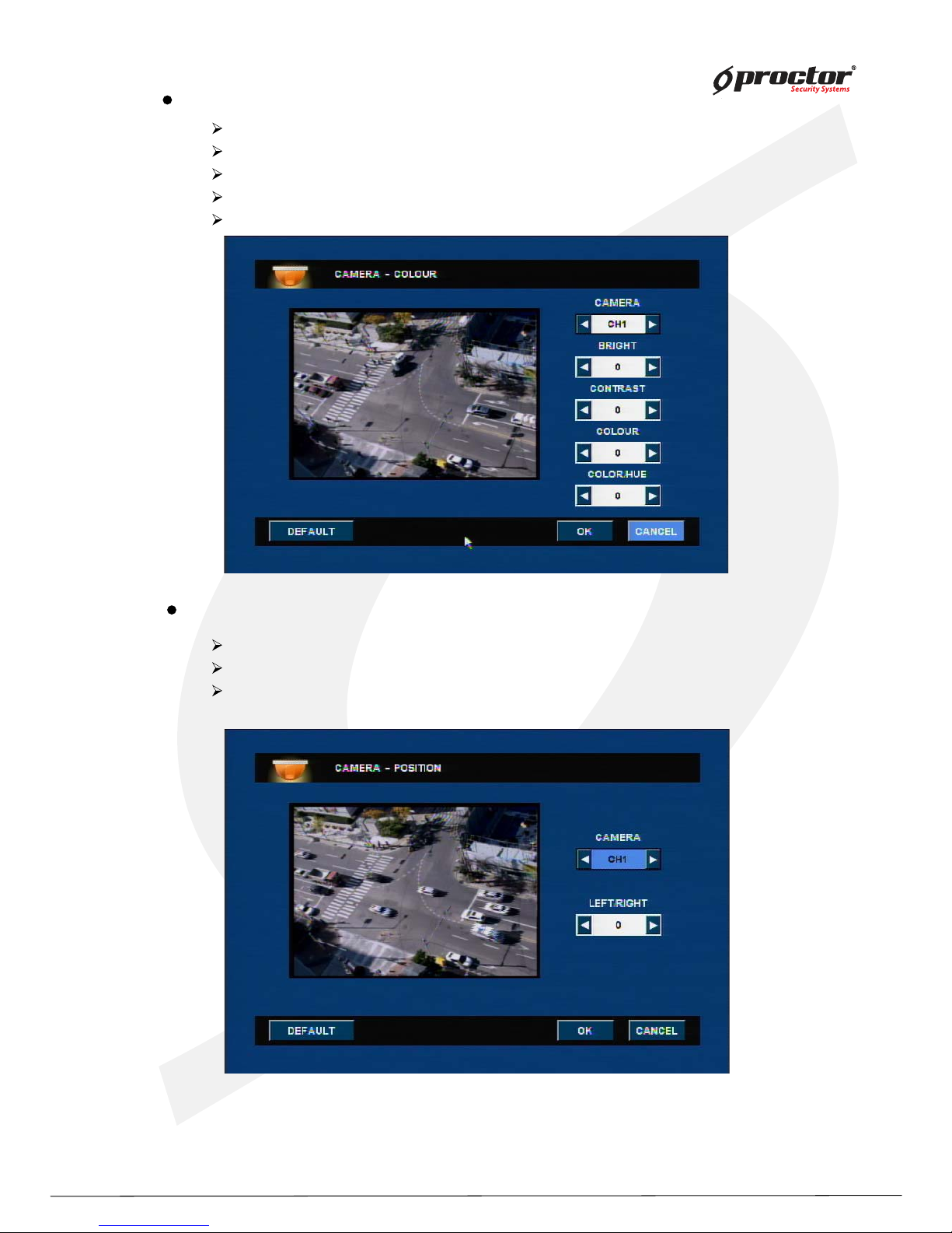
Camera setup – COLOUR
camera – select a camera.
bright – adjust color brightness.
contrast – adjust color contrast.
color – adjust camera color
default value – set it as default value.
Camera setup – position
camera – select a camera
right/left – move the camera to right and left.
default value – set it as default value.
Page 49
Standalone DVR
4 4
Page:
User Manual Ver. 2.2
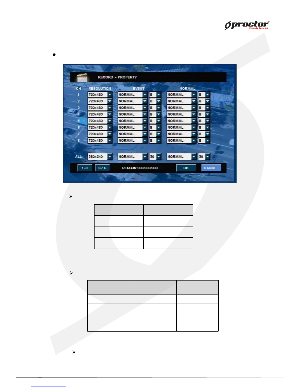
Record setup
NTSC PAL
720 x 480 720 x 576
720 x 240 720 x 288
352 x 240 352 x 288
Recording quality Display quality
HDD capacity
needed
Basic Low Small
Normal Normal Medium
High Good Large
best Very good Very large
Record setup – Property
Frame rate
set frame rate for each channel.
resolution – set recording resolution for each channel.
q uality – set recording q uality for each channel.
Page 50
Standalone DVR
45
Page:
User Manual Ver. 2.2
C Continuous recording
E
Recording when even occurred
I C(continue)+E(event)
(Blank)
Not recording
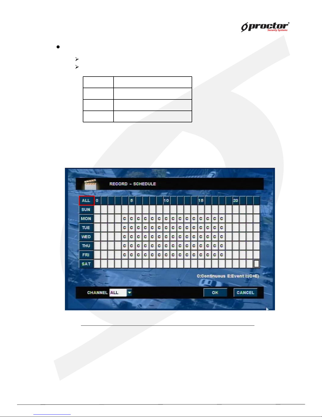
Record setup – schedule
system records according to set schedule.
see below to see how to set up schedule.
(1) Select a channel to set up schedule.
(2) Select day/time to record and press ‘ENTER/OK’ button.
(3) it shifts to different type as you press ‘ENTER/OK’button.
» Click the “All” button then all schedule will be applied same mode.
Page 51
Standalone DVR
46
Page:
User Manual Ver. 2.2
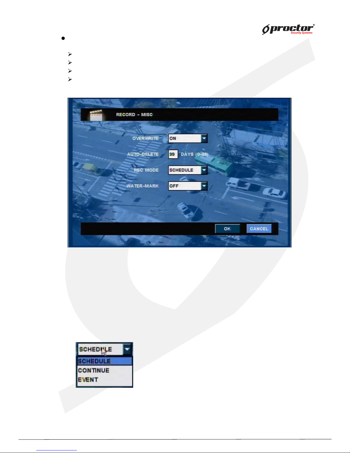
Record setup – miscellaneous
overwrite – erase previous video data and record over it when HDD is full.
auto delete – automatically delete data after set date.
continuous record – you cannot stop recording while it is in process as it continuously records.
watermark – activate watermarking function.
Note) when setting as ‘ON’ for ‘Water Mark’ option, all recording files
are applied with watermarking, this recorded file can be checked
at Backup Viewer if someone is altered or edited recorded file with
intentional purpose.
(please check out Backup-watermark section of user manual.)
SCHEDULE: Record according to schedule setting.
CONTINUE: Continuous recording for all day / time.
EVENT: Only recording when the event occurred.
Event recording time PRE/POST only records during
recording setting time.
(In reference to event setup-misc set up page.46)
[REC MODE]
Page 52
Standalone DVR
4 7
Page:
User Manual Ver. 2.2
Event setup
NOTE : you have to set it as ‘ Even recording’ at ‘ Schedule record setup’ to use this functi on .
NOTE : you have to set it as ‘ Even recording’ at ‘ Schedule record setup’ to use this functio n .
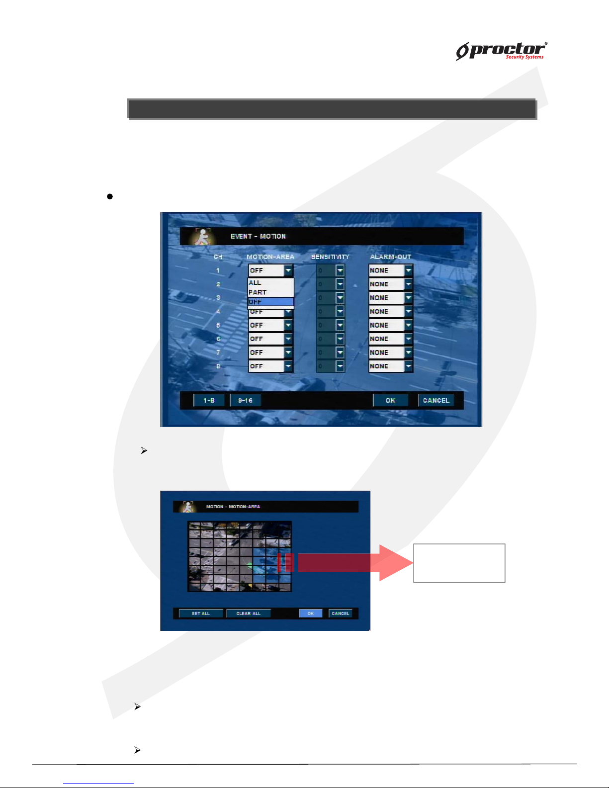
Motion
detection area
Event Setup - Motion
sensitivity – select a level of detection sensitivity.
level of sensitivity : 0 < 1 < 2 < … .. < 9
Alarm out – activate alarm on motion detection.
Motion area – select detecting area.
(1 ) all – detect the whole camera screen.
(2) part – detect motion detection area.
(3 ) off – no motion detection.
W hen the event (sensor/motion/video loss) is detected on DVR side, DVR alerts by message
pop- up, beep sound or E- mail notification. Y ou must setup event recording on schedule record
setup to use this function.
Page 53
Standalone DVR
48
Page:
User Manual Ver. 2.2
Event setup - sensor
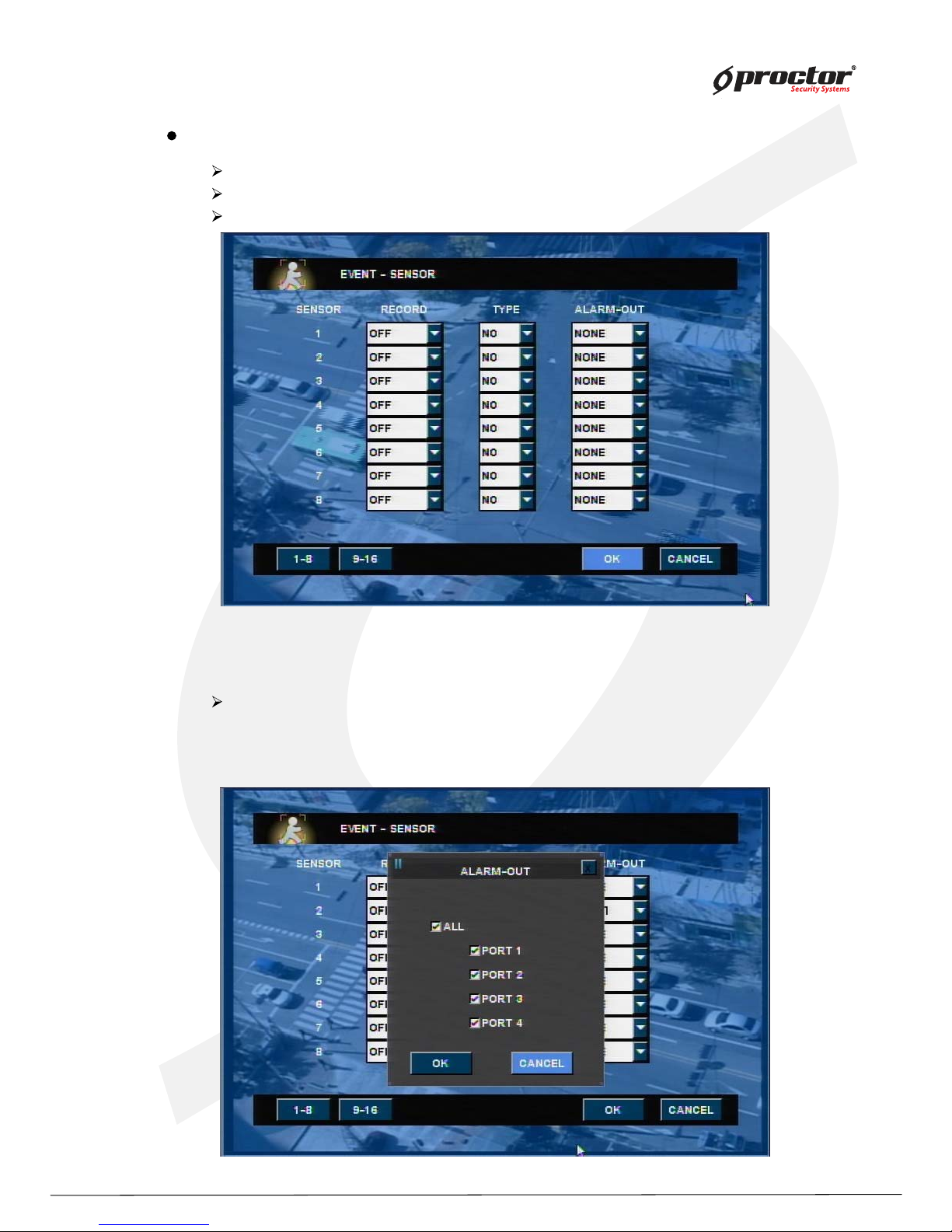
Record – select camera to record on sensor detection.
Type – select sensor type.
Alarm out – activate alarm out on sensor detection.
If you choose ‘multi’ in the previous record menu, you can record all channel or
specific channel.
Click channel you want to choose after unchecked “All”.
Page 54
Standalone DVR
49
Page:
User Manual Ver. 2.2
Event set up – VLOSS
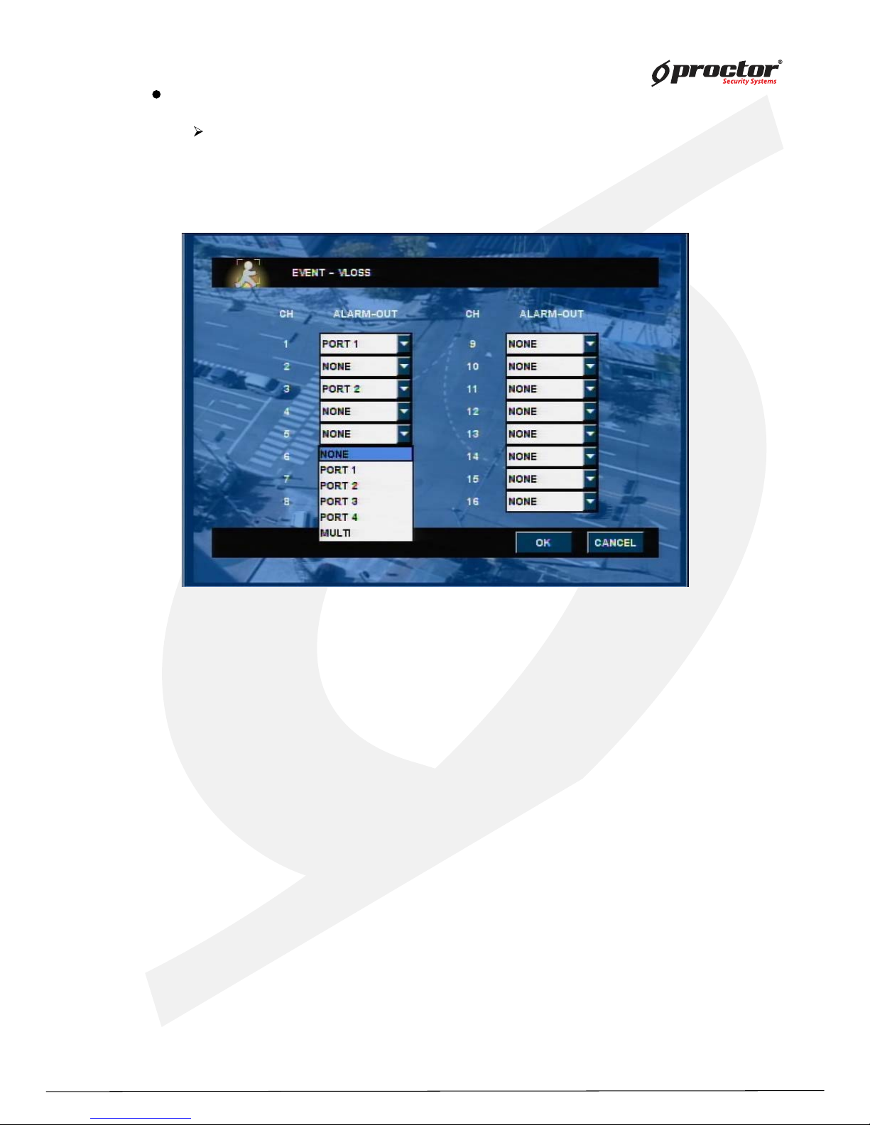
ALARM-OUT – Select Alarm port.
NONE: Alarm port does not output.
PORT 1: Beep occurs to the specified Alarm port.
Multi : Beep occurs to the selected Alarm port.
(Some models do not apply.)
•Note:
1) Alarm output port can be specified by the overlap.
2) Alarm port number can be different according to model.
Page 55
Standalone DVR
50
Page:
User Manual Ver. 2.2
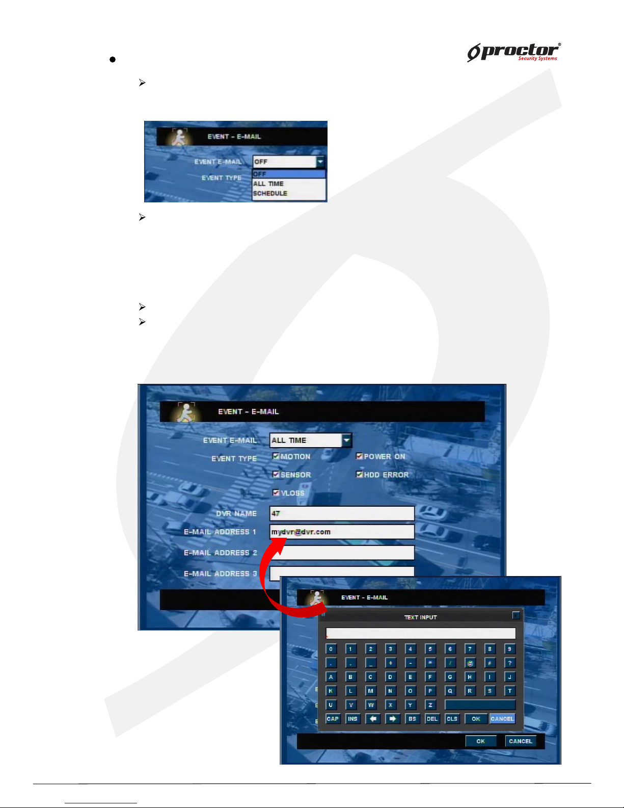
EVENT E-MAIL(OFF/ALL_TIME/Schedule)): Choose an e-mail sending function.
If you select ‘schedule’, you can receive e-mail which is desired day/time as setting
‘E-MAIL SCHEDULE’.
Choose EVENT TYPE
- MOTION(ON/OFF): When motion is detected, you can notice by e-mail.
- POWER ON : When power is on or booting, you can notice by e-mail.
- SENSOR(ON/OFF): When sensor is detected, you can notice by e-mail.
- HDD error: When Internal HDD fails, you can notice by e-mail.
- VLOSS(ON/OFF): You can notice about camera input down/up.
DVR NAME: E-mail as selected DVR-Name.
E-MAIL ADDRESS: You can specify up to 3 recipient.
NOTE: If Motion or SENSOR often detect, you might receive many e-mails.
So we recommend this setting when you are necessary.
Event setup – E-MAIL
Page 56
Standalone DVR
51
Page:
User Manual Ver. 2.2
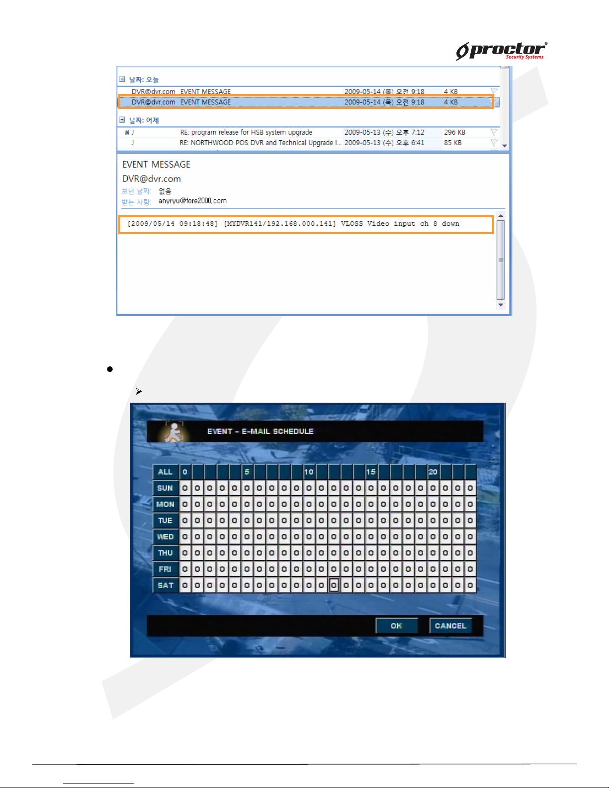
EX. E-mail notification you would receive.
[Example for received email]
Event setup – E-MAIL SCHEDULE
You can set up schedule for 24 hours a week.
This schedule setting is for received e-mail from Saturday to Sunday at 8:00pm~6:00am.
You can notice event happening by an e-mail while you don’t work.
Page 57
Standalone DVR
52
Page:
User Manual Ver. 2.2
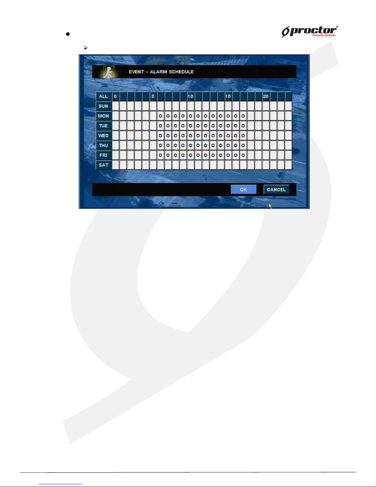
Event setup – ALARM SCHEDULE
You can set up schedule for 24 hours a week.
This setting is for alarm from Friday to Monday at 09:00am-5:59pm.
You can recognize any events by alarm during working.
Page 58
Standalone DVR
53
Page:
User Manual Ver. 2.2
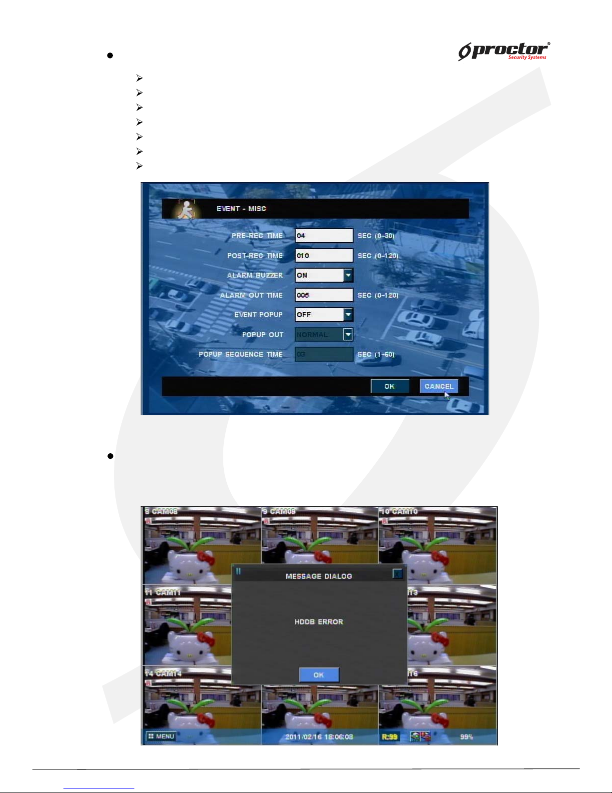
Event setup – MISC
pre-recording time – setup pre-recording time on the selected event detection.
post-recording time –setup post-recording time on the selected event detection.
ALARM buzzer – enable alarm buzzer on the selected event detection.
alarm out time – setup duration to activate alarm out on the selected event detection.
EVENT POPUP – select ‘on’ to enable message pop-up on the selected event detection.
POPUP OUT - select type of video out for message pop-up ; VGA or SPOT.
POPUP Sequence time – setup POPUP sequence time. (1~10sec)
HDD Failure – alert by E-mail notification
When HDD fails, the system alerts by error message pop-up, beep sound as well as E-mail
notification. (ex. HDD Disk B drive error)
Page 59
Standalone DVR
54
Page:
User Manual Ver. 2.2
Storage
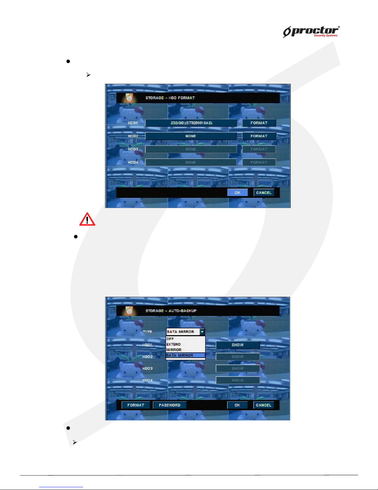
Storage – HDD format
You must format HDD when you install HDD.
Storage – AUTO-BACKUP
All saved data will be removed after HDD format process!
EXTEND: User can use EXTEND backup through connected USB external HDD.
Data(which is need to be deleted) will be send to USB external HDD if Main HDD is full.
MIRROR: User can use MIRROR backup through connected USB external HDD.
Main HDD and external HDD will save same data at the same time.
SATA MIRROR: Save same data on 2 separated HDD.(with internal HDD)
STORAGE– MISC
Beep sound setting for warning message form Disk error.
- OFF: No beep sound and activate error message.
- ON : Beep sound on and activate error message.
Page 60
Standalone DVR
55
Page:
User Manual Ver. 2.2
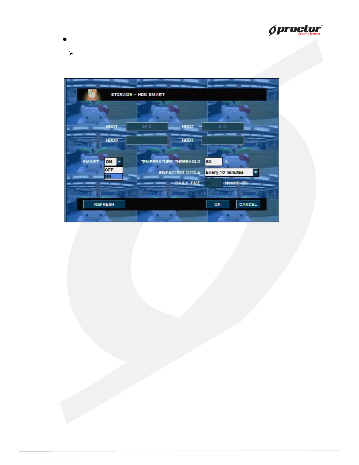
STORAGE– HDD SMART
You can check HDD’s temperature and if temperature is higher than setting ,
you can set the alarm.
(1) HDD1, HDD2 : Inform the current temperature and displays for installed HDD.
(2) SMART ON/OFF: If temperature is higher than setting, you can also set the alarm or not.
(3) TEMPERATURE THRESHOLD: You can set up when SMART menu is ON.
(4) INSPECTION CYCLE: Set up inspection cycle .
- EVERY 10 minutes : Check up each 10 minutes.(00, 10, 20, 30,40,50)
- Hour : Check up regular time.(00 hour, 01 hour, 02 ho
urs,…..22 hours, 23 hours)
- Daily : Check up every days as a fixed time.
Example) If you set up 09a.m, Check up every 09:00 a.m.
‘REFRESH’ button: Display HDD’s current temperature as refresh.
Page 61
Standalone DVR
56
Page:
User Manual Ver. 2.2
Network
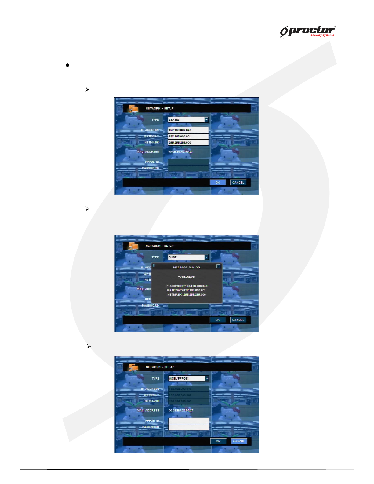
Network – setup
static – Input static IP address and gateway, net mask.
DHCP – System automatically recognizes IP address.
Click “OK”, after selecting DHCP.
You will have IP address.
PPPOE – ADSL only, input registered ID and password.
Page 62
Standalone DVR
57
Page:
User Manual Ver. 2.2
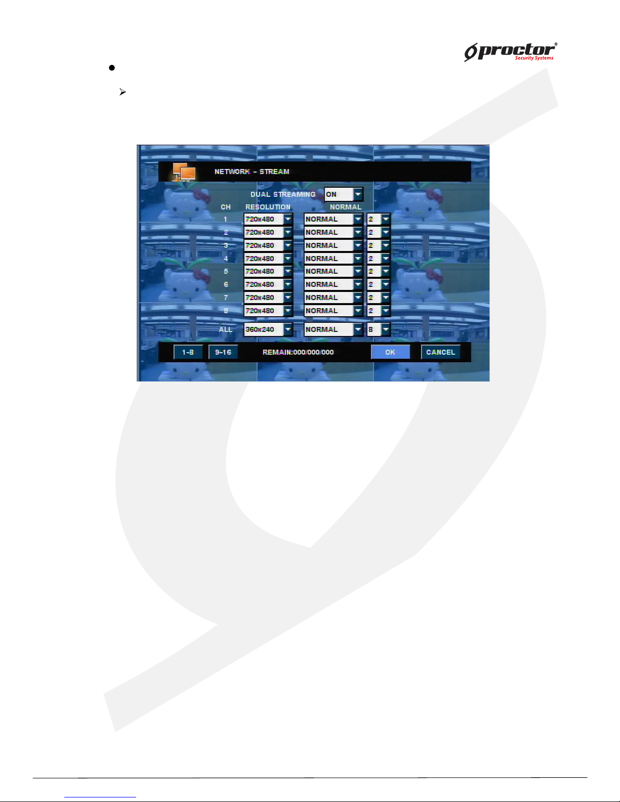
NETWORK– STREAM
If CMS or web CMS access, Dual stream function offers in order to reduce the load
on the network.(default rate is ON.)
(1) DUAL STREAM
- ON: Transmit to each channel’s setting value.
- OFF: Transmit according to DVR Set’s recording setting value.
(2) Resolution: You can choose 3 kinds of resolution.
- 720x480 / 720x240 / 360x240.
(3) Normal: You can choose 4 kinds of video quality.
- Basic / Normal / High/Best
(4) Frame : You can choose the number of transmitted frame for each channel.
The total number of frame can be different
according to model.
(5) If you want to apply all channels, select “ All”.
Note: If DUAL STREAM is “ON “, network can take the load.
Please use properly this function according to network status.
Page 63
Standalone DVR
5 8
Page:
User Manual Ver. 2.2
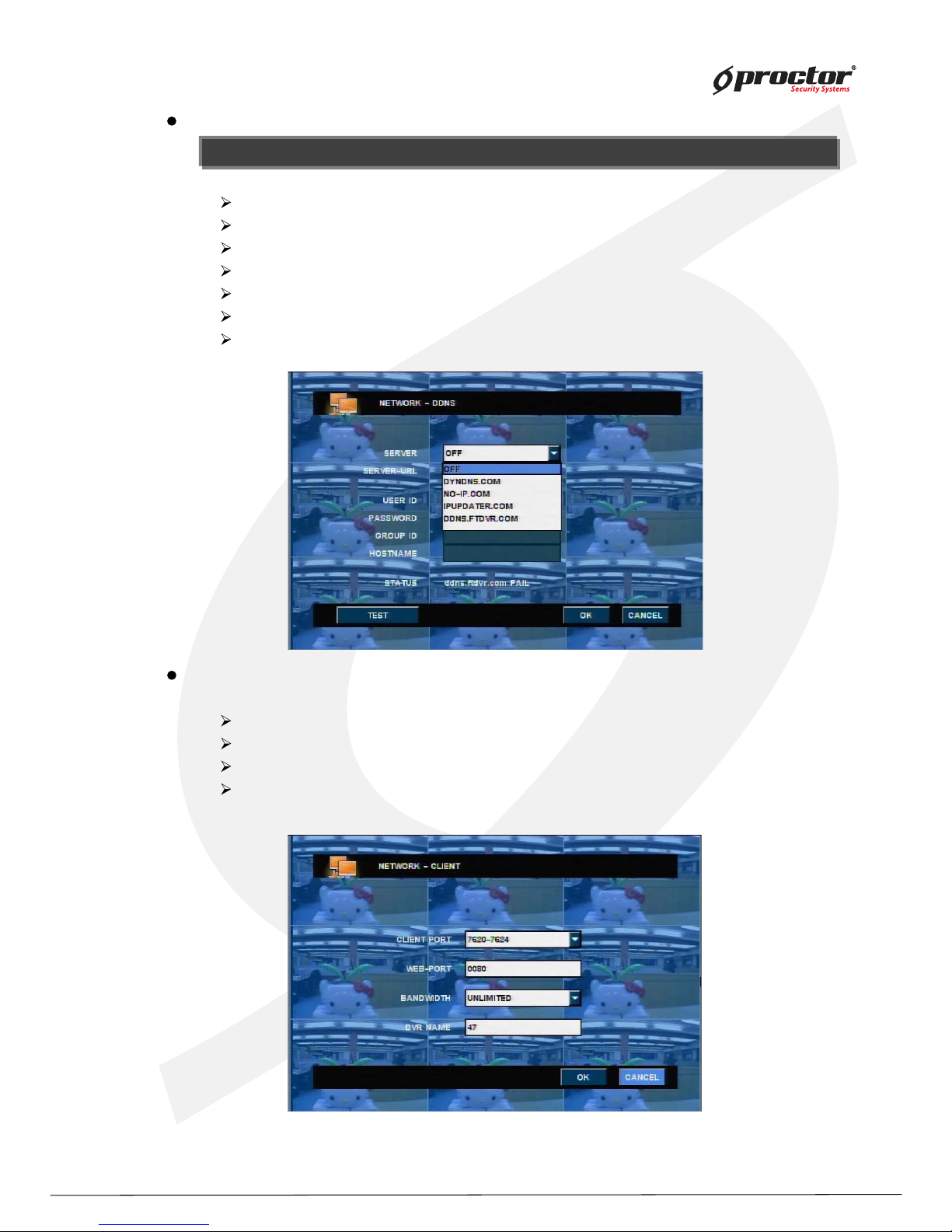
Network - DDNS
NOTE : system supports free DDNS sites such as dyndns.com, ipupdater.com.
NOTE : system supports free DDNS sites such as dyndns.com, ipupdater.com.
SERVER – select registered server.
SERVER- URL – indicate registered server URL
USER ID – input ID registered to server.
PASSW ORD – input password registered to server.
GROUP ID – input group ID registered to server.
STATUS – indicate operation status of DDNS.
TEST– try to connect with ID and password registered to server.
Client port – select port to connect.
W eb port – select web port to connect to web browser.
Bandwidth - limit transmitting data capacity through the network.
DVR- Name - input DVR name to connect CMS S/W .
Client
Page 64
Standalone DVR
5 9
Page:
User Manual Ver. 2.2
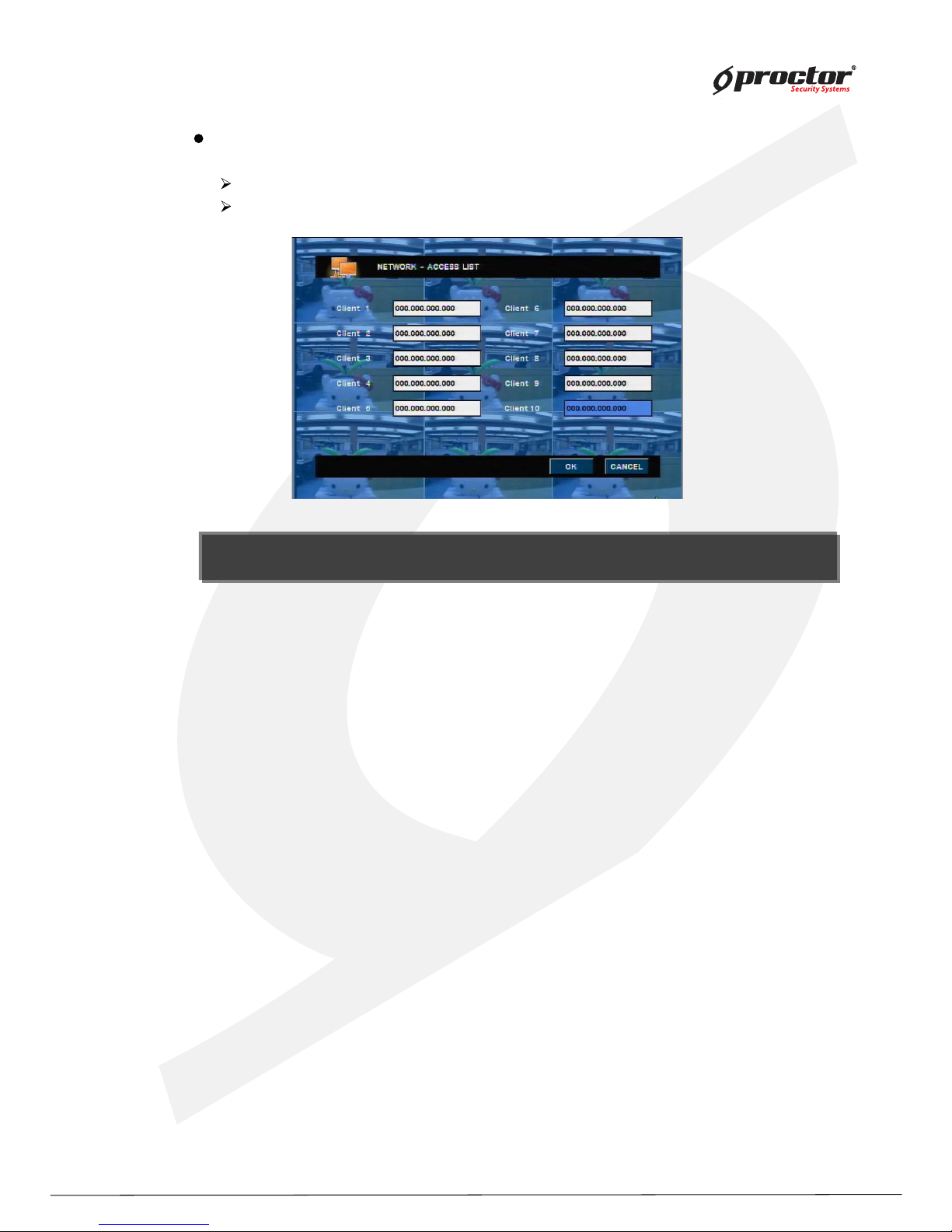
Access list
System can limit remote- PC, accessing network.
Able to register Static IP and only remote- PC with registered IP can access system.
NOTE : the system restricts all the other IPs, those are not re gis tere d if you onc e register an IP . I f you want
to access with all IP addresses, do not register any IP.
NOTE : the system restricts all the other IPs, those are not re gis ter ed if you on ce register an IP. If you want
to access with all IP addresses, do n ot regis t er an y IP .
Page 65
Standalone DVR
60
Page:
User Manual Ver. 2.2
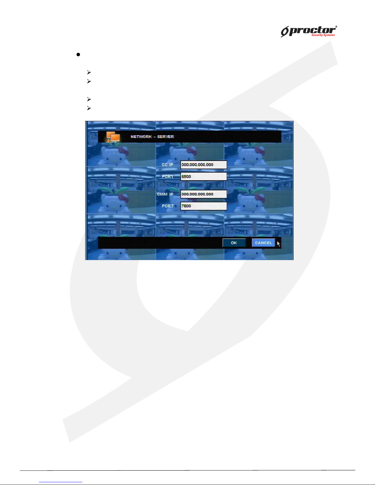
Server
CC IP – input connection info of CAMS CC.
PORT – input connection port of CAMS CC. (default value: 6500)
CMM IP – input connection info of CAMS CMM.
PORT – input connection port of CAMS CMM. (default value:7600)
Page 66
Standalone DVR
6 1
Page:
User Manual Ver. 2.2
Sy stem
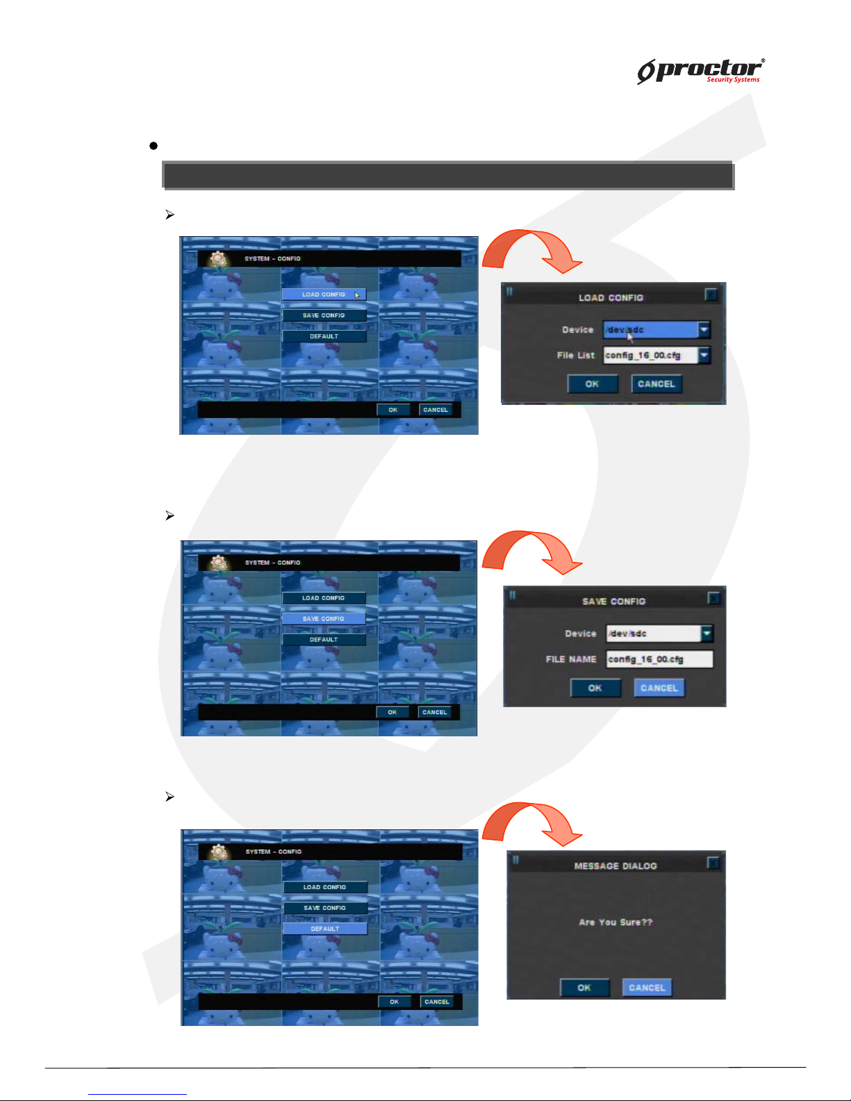
Sy stem – Config uration info
NOTE : you can save the set values for menu to USB storage.
NOTE : you can save the set values for menu to USB storage.
Default value – set it as default value.
Load configuration – loads saved configuration information.
Save configuration – save the values set in the current menu.
Page 67
Standalone DVR
6 2
Page:
User Manual Ver. 2.2
classification display
YY/MM/DD 2008/03/03
MM/DD/YY 03/03/2008
DD/MM/YY 03/03/2008
classification display
AM/PM 01:39:01 PM
24 HOURS 13:39:01
Sy stem – Time manag ement
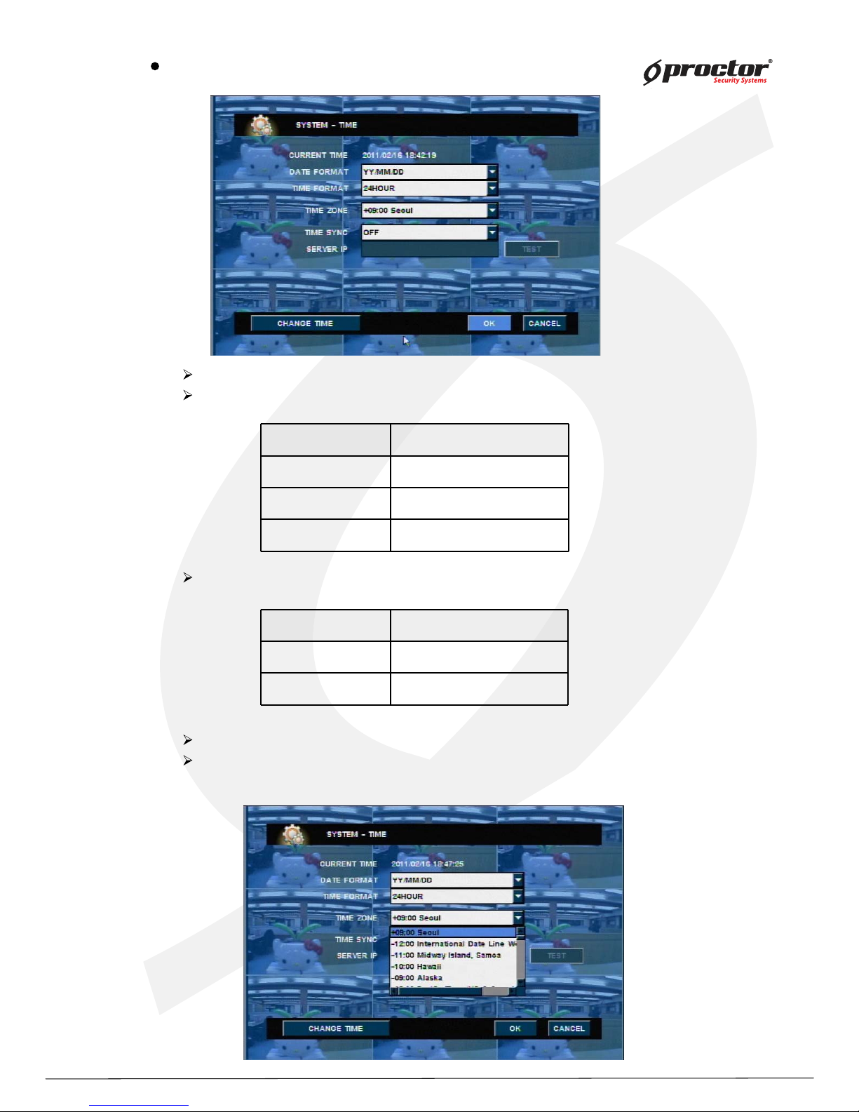
Current time – indicates current time of system.
Date format – select date format to display.
Time format – select time format to display.
Day Light Saving – Day light Saving Time area sets up automatically.
Time z one – Select the time different from standard time of Time- Server
then check automatically the check- box of on/off option.
Page 68
Standalone DVR
6 3
Page:
User Manual Ver. 2.2
NOTE : be cautious when you change system time. Because if you set the system time earlier than th e time
originally set, the saved data after changed system time will be deleted.
NOTE : be cautious when you change system time. Because if you set the system time earlier than the time
originally set, the saved data after changed system time will be deleted.
Time synchroniz ation
W hen using TIME SY NC Function, please select “ SNTP” . And then, System can
Automatically connects to internet time- server to check current time.
Server IP – input time- server IP address.
Omit ‘ www’ .
Select ‘ ENTER/OK ’ and check if time- server works.
correct input
wrong input
Change time – change system time.
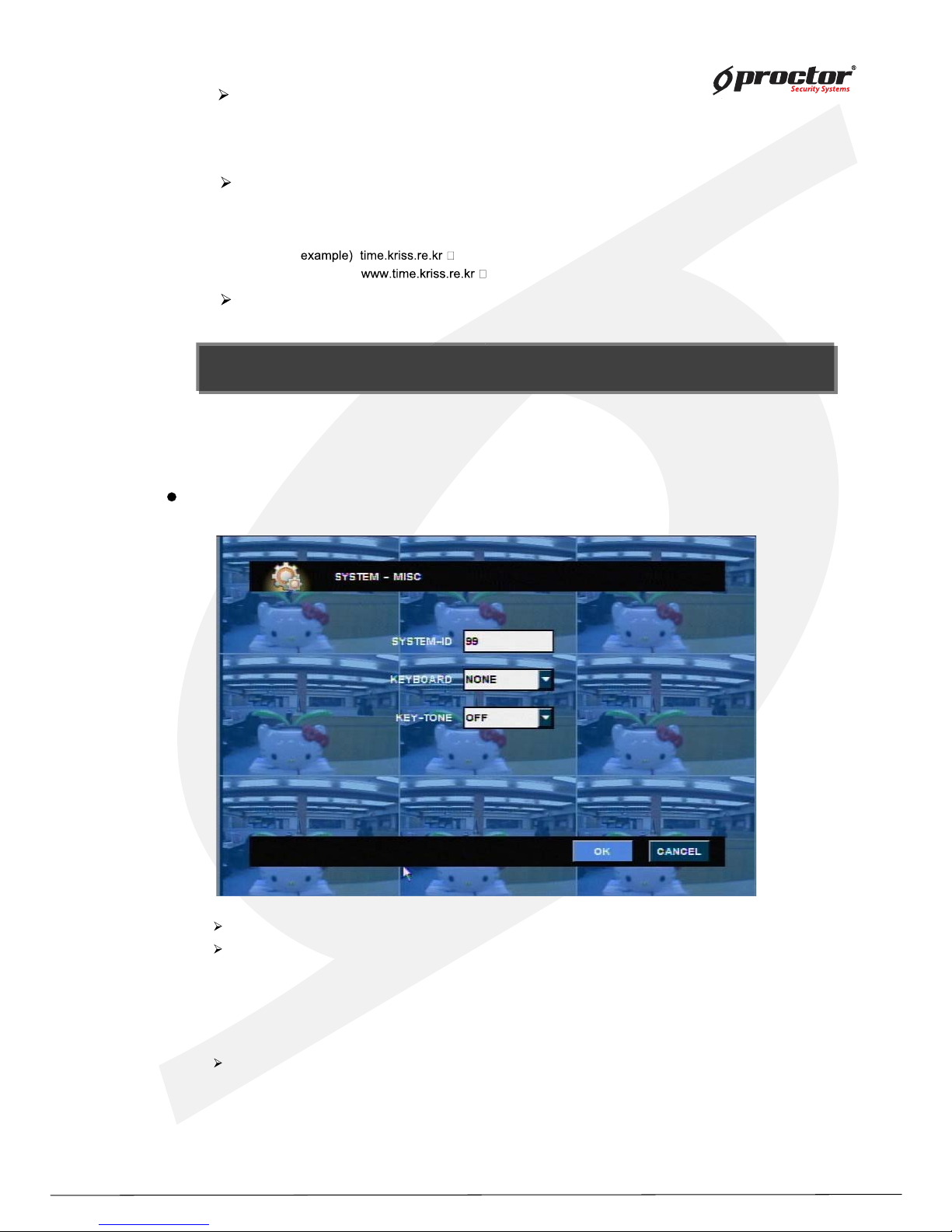
SY STEM – MISC
SY STEM- ID – To use RS- 4 8 5 or remote control, you must input SY STEM ID.
K EY BOARD – Y ou can use keyboard controller.
Supported keyboard controller as follows.
- W ONW OO
- CH UBB
- H ISH ARP
K ey - TONE : W hen you use a mouse, front keyboard or remote control etc,
you can turn on/off the sound.
Page 69
Standalone DVR
64
Page:
User Manual Ver. 2.2
System – USER/Password management
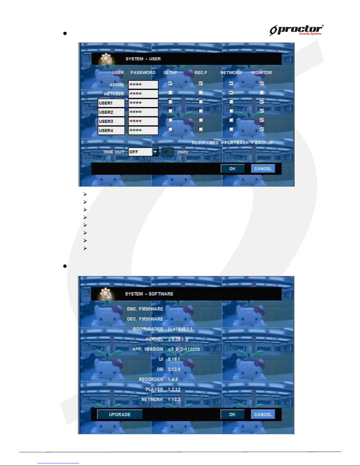
ADMIN password – change the administrator password.
NETUSER password – from network user password by CMS.
USER password – change the USER and user password for CMS.
SETUP check – set whether to input user password or not before accessing system menu.
REC.F check – set whether to Record + Playback + Network and Backup.
NETWORK check – via network user by CMS.
MONITOR check – Monitor this DVR system.
TIME OUT – If there is no input during schedule time, automatically logout.
System – Software
Show current software version.
Upgrade firmware software.
Page 70
Standalone DVR
65
Page:
User Manual Ver. 2.2
System – System shutdown
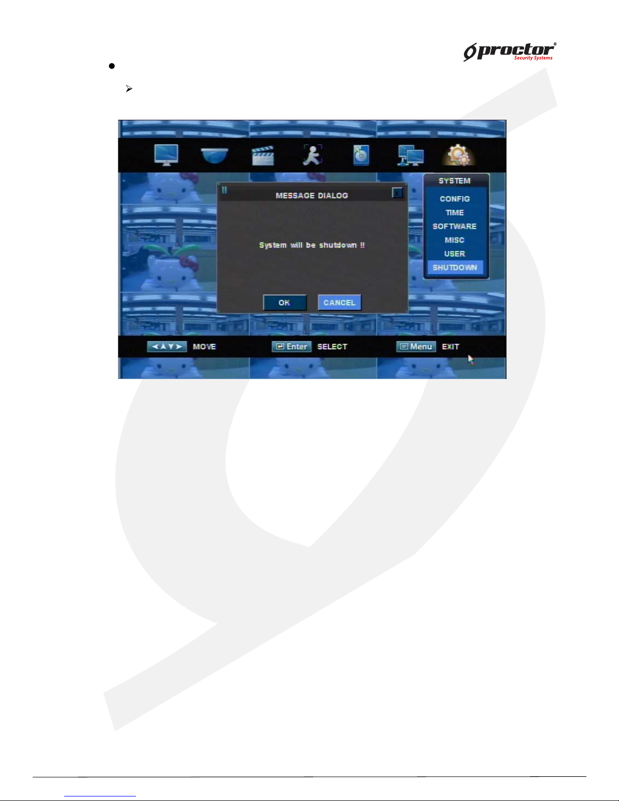
Select ‘’System shutdown’. If you see the message “system will shutdown”,
you can shutdown system.
Note: To protect your computer system,
If you want to you turn off on your computer’s power,
you must turn off after selecting shutdown on system menu.
If you don not follow up, your computer can be damaged firmware or
can be occurred a fatal error in the system.
Page 71
Standalone DVR
66
Page:
User Manual Ver. 2.2
Chapter 5 Firmware Upgrade
Page 72
Standalone DVR
6 7
Page:
User Manual Ver. 2.2
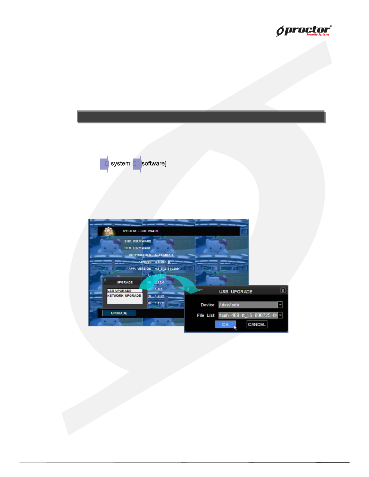
(1 ) Copy the provided firmware file to USB memory stick.
(2) Connect USB memory stick to system USB port.
(3 ) Press ‘ Menu’ button and move to the nex t software.
[ menu
(4 ) Y ou will see a new box if you select ‘ Upgrade’
(5) Y ou will see menu like below if you select ‘USB upgrade’ .
(6 ) Device – select USB device with firmware file.
(7 ) File list – select the right firmware file.
(8 ) Select ‘ ENTER/OK ’. System automatically upgrades. System will reboot after upgrade
is completed.
NOTE : There are two ways to upgrade firmsare.
(1 ) USB upgrade – upgrade system using USB memory stick.
(2) NETW ORK upgrade – upgrade system by internet connection.
USB upg rade
NOTE : The firmware file should be sav e d in rout e direc t ory of the USB d ev ic e.
NOTE : The firmware file should be saved in route directory of the USB device.
Page 73
Standalone DVR
6 8
Page:
User Manual Ver. 2.2
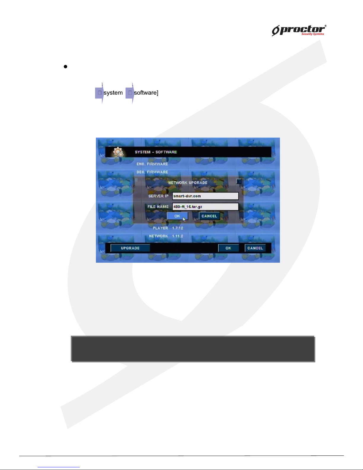
(1 ) Press ‘ Menu’ button and move to the nex t software.
[ Menu
(2) Y ou will see a new box if you select ‘Upgrade’ .
(3 ) Select ‘ Network upgrade’ .
(4 ) Select ‘ Server IP’ with firmware file and file name. then select ‘ ENTER/OK ’ .
(5) Y ou can manually input server IP and file name if the system appointed server IP
and file name is different.
(6 ) System will automatically reboot after upgrade is completed.
Network upg rade
Network upg rade
NOTE : Network upgrade function is an upgrade method by using int erne t.
It depends on network place or inter net s t at us , user cannot be accessed.
NOTE : Network upgrade function is an upgrade metho d b y using i ntern e t.
It depends on network place or inter net s t at us , user cannot be accessed.
Page 74

Standalone DVR
6 9
Page:
User Manual Ver. 2.2
C hap ter 6 C M S – D isp lay M o de
Display Mode
Setup Mode
Search mode
Page 75
Standalone DVR
7 0
Page:
User Manual Ver. 2.2
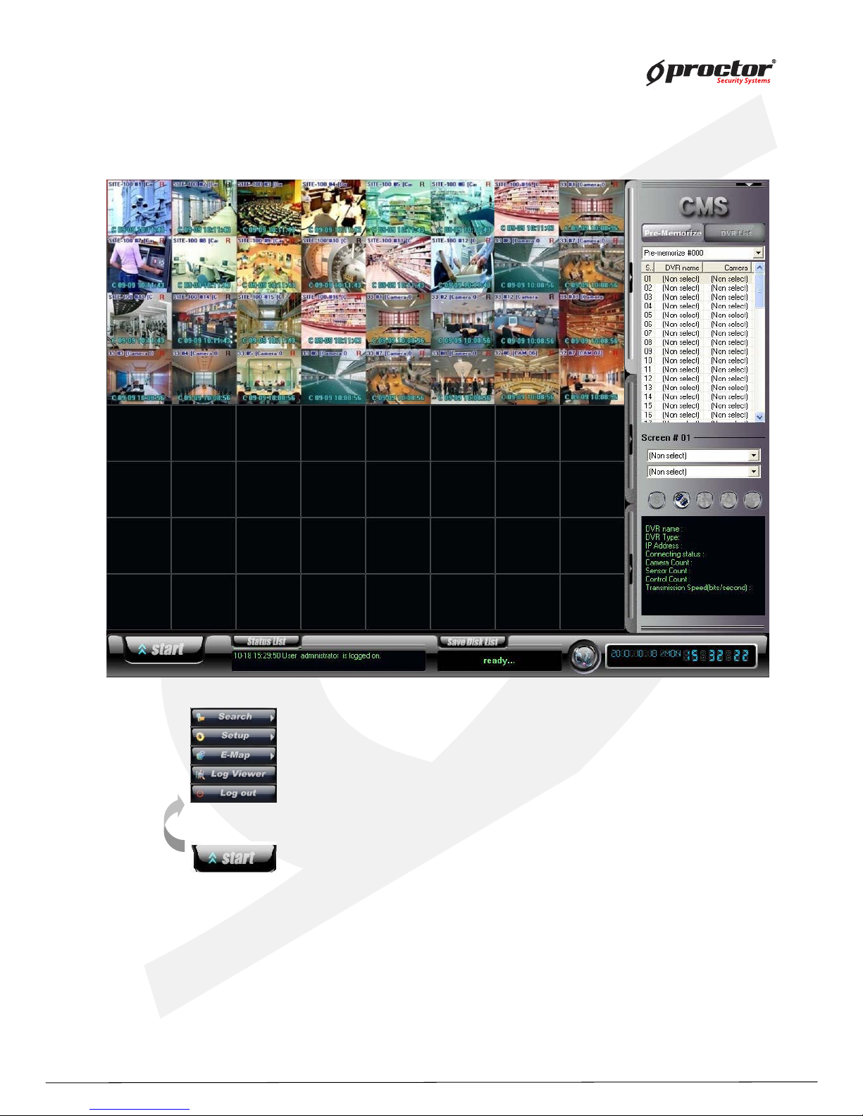
Start : can ex ecute overall CMS functions such as log in/out, Setup, Search.
Search :
search saved image by remote or local search.
Setup : setup on CMS system.
E-Map :
Monitor DVR sites, Camera, Sensor, and Control through E- MAP.
Log Viewer : can check or print ‘ Log file’ in the CMS system.
Log out : Log in/out
User Interface
Page 76
Standalone DVR
71
Page:
User Manual Ver. 2.2
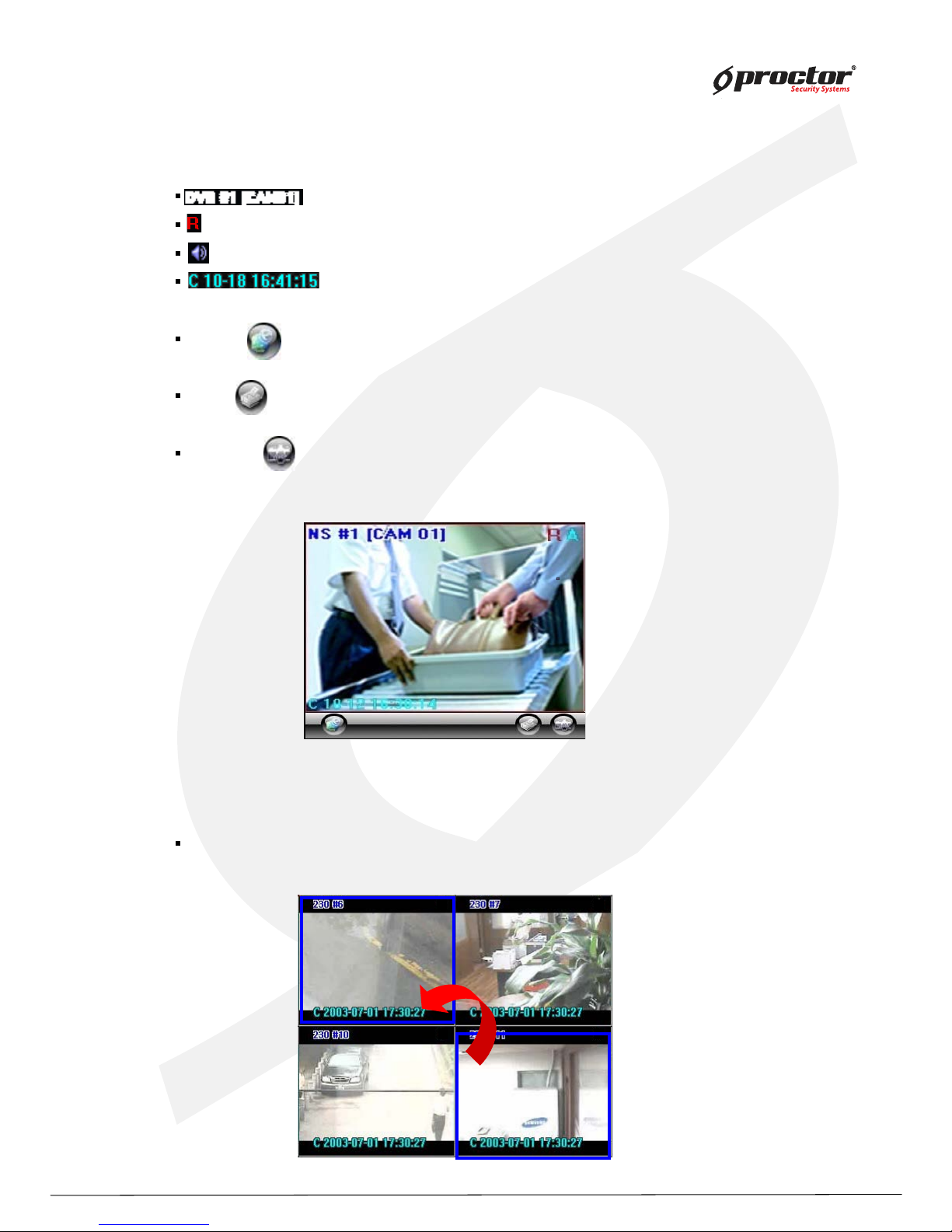
: It represents site code, screen number, and camera name.
: “R” It represents this image is saving on CMS.
: It represents this image is with audio data.
: It represents the time of data transmitted.
“10-12 16:30:14” DVR System time
E-Map : Click this button to enable ‘E-MAP’.
Print : Click the button to print the image.
Snapshot: Click the button to save the appropriated image.
(Location for saving - C:\CMS_2KV3\Image)
Display screen
Screen Switch on Display mode : put the mouse on the screen, and click right mouse
button and drag to the desired screen to display.
☞ E-Map, Print, Snapshot button shown on one division screen.
Page 77
Standalone DVR
7 2
Page:
User Manual Ver. 2.2
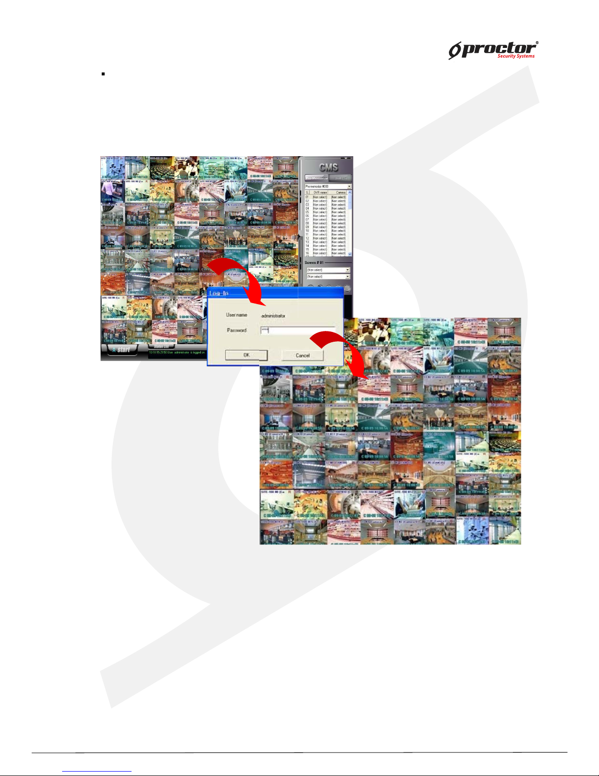
Full Screen Mode : Only normal main screen is available to apply full screen mode in
CMS function.
- Double click right button of mouse on normal main screen.
- Enter ID and password and click “ OK ” .
(Normal Mode)
(Full Screen Mode)
- Double click right button of mouse on full screen mode.
- Enter ID and password and click “ OK ” .
▪ Normal Mode → Full Screen Mode
▪ Full Screen Mode → Normal Mode
Page 78
Standalone DVR
73
Page:
User Manual Ver. 2.2
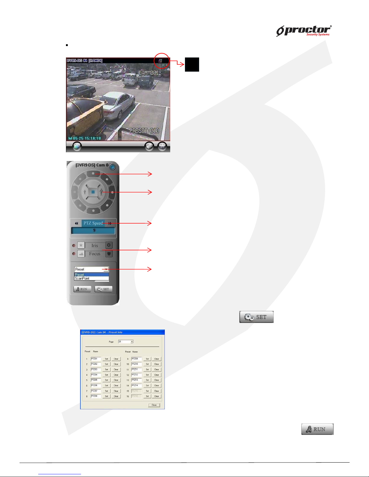
PTZ Controller: can control PTZ from the remote site of CMS via network.
- Click ICON of PTZ as the left image.
- Can control up , down, left & right direction of PTZ.
- Can Zoom IN / OUT of PTZ.
- Can control speed of Zoom IN & OUT & its Movement of PTZ.
- Can use the function of Preset/Scan point for PTZ.
- Can control Iris, Focus of PTZ..
- Preset Setting: after selecting Preset, click SET button.
User move PTZ on the direction of up, down, left & right,
with Zoom In & Out to the position which user want to move,
and then click Set Button.
Preset setting can be available up to 64 times.
-Preset Operation: select Preset at PTZ Main controller, and then input Preset number at
Number, if click RUN Button, move to Preset position which was input number.
Page 79
Standalone DVR
74
Page:
User Manual Ver. 2.2
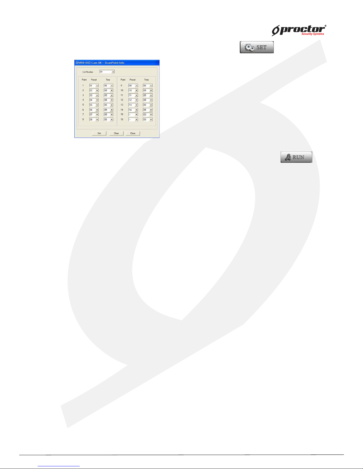
- ScanPoint Setting: after selecting ScanPoint click SET Button.
According to the order of the left image menu, select
Preset number & dwell time.
ScanPoint can be set up to 4 times per camera.
- ScanPoint Operation: Select ScanPoint at PTZ Main controller, input ScanPoint number on
number, and then click RUN Button, can be operation for Scanpoint function.
Page 80
Standalone DVR
75
Page:
User Manual Ver. 2.2
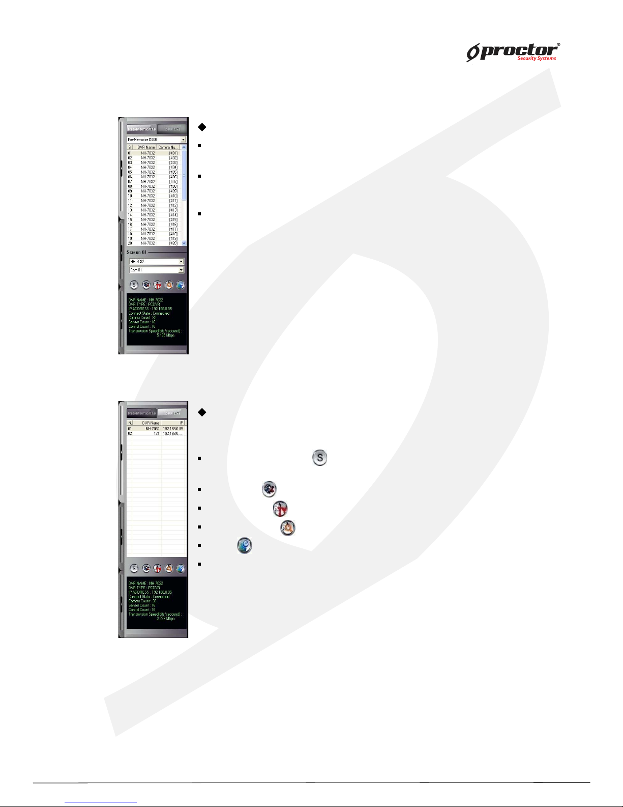
Single / Multiple Mode : Click the button to activate single or multiple
mode as pre memorize access.
Connection : Click the button to connect or disconnect to DVR.
Remote Setup : Click the button to use remote setup for selected DVR.
Remote Search : Click the button to use remote search for selected DVR
.E-map : Click the button to use E-MAP for selected DVR.
Status : It represents the information and the status of accessed DVR.
Connection list & Sensor/Control & Screen Division
Connection list
There are two ways which are Pre-Memorize and DVR list on the connection list.
Pre-Memorize
show the information for each DVR site on the list.
Screen list:
can change the position of camera after selecting screen or list.
DVR list
Monitor each screen in order without extra display setup.
Page 81
Standalone DVR
7 6
Page:
User Manual Ver. 2.2
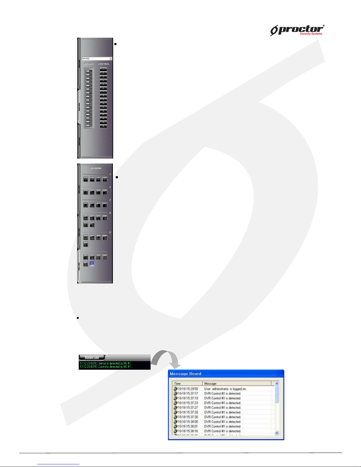
Sensor/Control
- Select the registered site name, then, click each button of sensor and control
to activate.
Screen Division
- Various surveillance modes available through division buttons.
Status
Status List : Click the button to check the details of event messag e.
Status List : It represents the event message of CMS program.
Page 82
Standalone DVR
7 7
Page:
User Manual Ver. 2.2
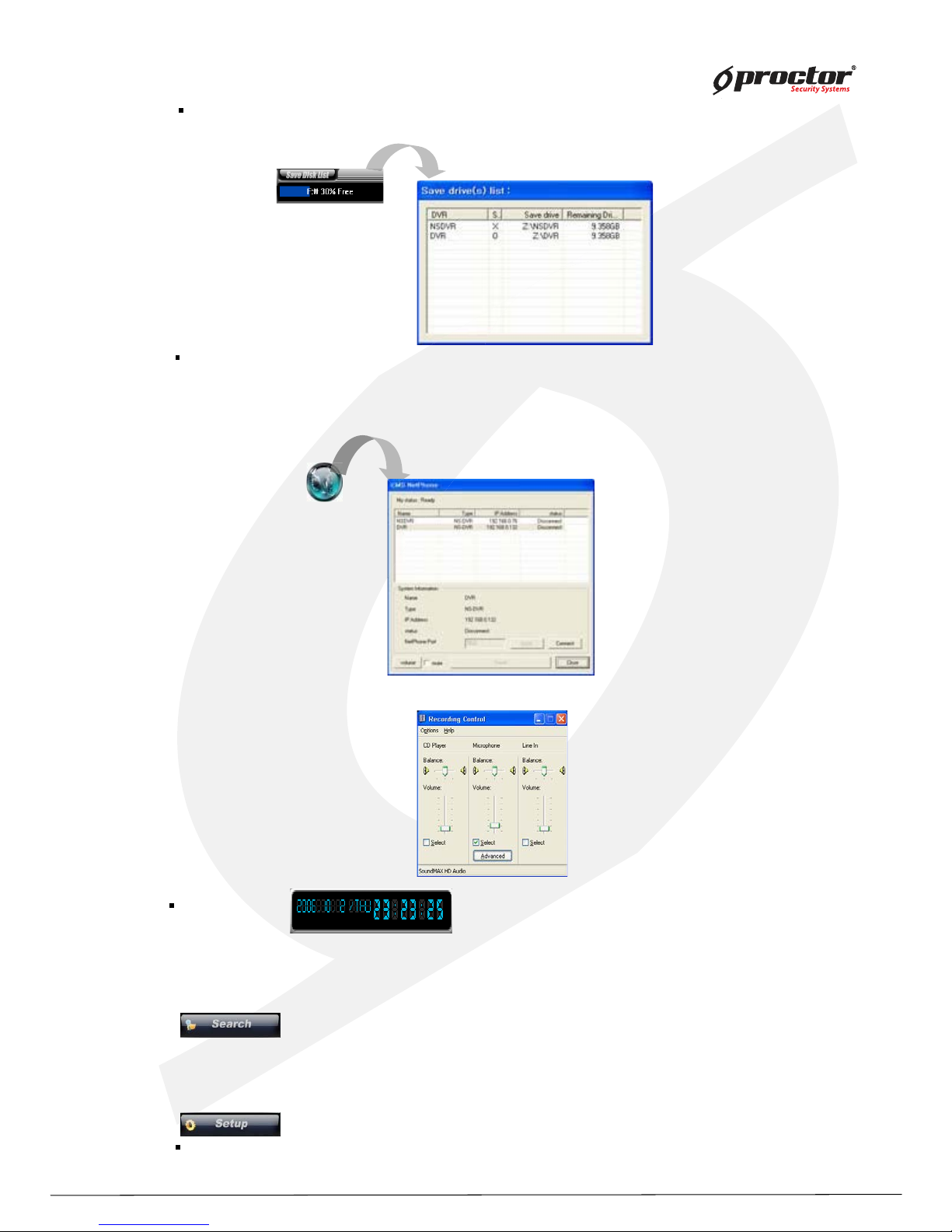
Dig ital-Clock : It represents the date of CMS system.
Display format can be changed.
Save Disk List : Select the drive to setup save disk for the data from each DVR site.
Save Disk List : Free space of and the status of each drive can be check ed.
Sy st em Utility
Search : access to various search mode, general search, special search (real time, multi time,
day search), obj ect search etc.
Setup : Setup on CMS system.
2W AY AUDIO : Audio communication between CMS and DVR available.
Click ‘ AUDIO CH AT’ button on CMS, and select DVR name to talk, then, click ‘ Talk’ button to send
* req uest to DVR site: Audio chat button will be flashed on/off on DVR site by req uesting
audio communication from CMS.
• Setup the port for 2way audio communication. Control the setup and volume of
microphone by volume button.
Page 83
Standalone DVR
78
Page:
User Manual Ver. 2.2
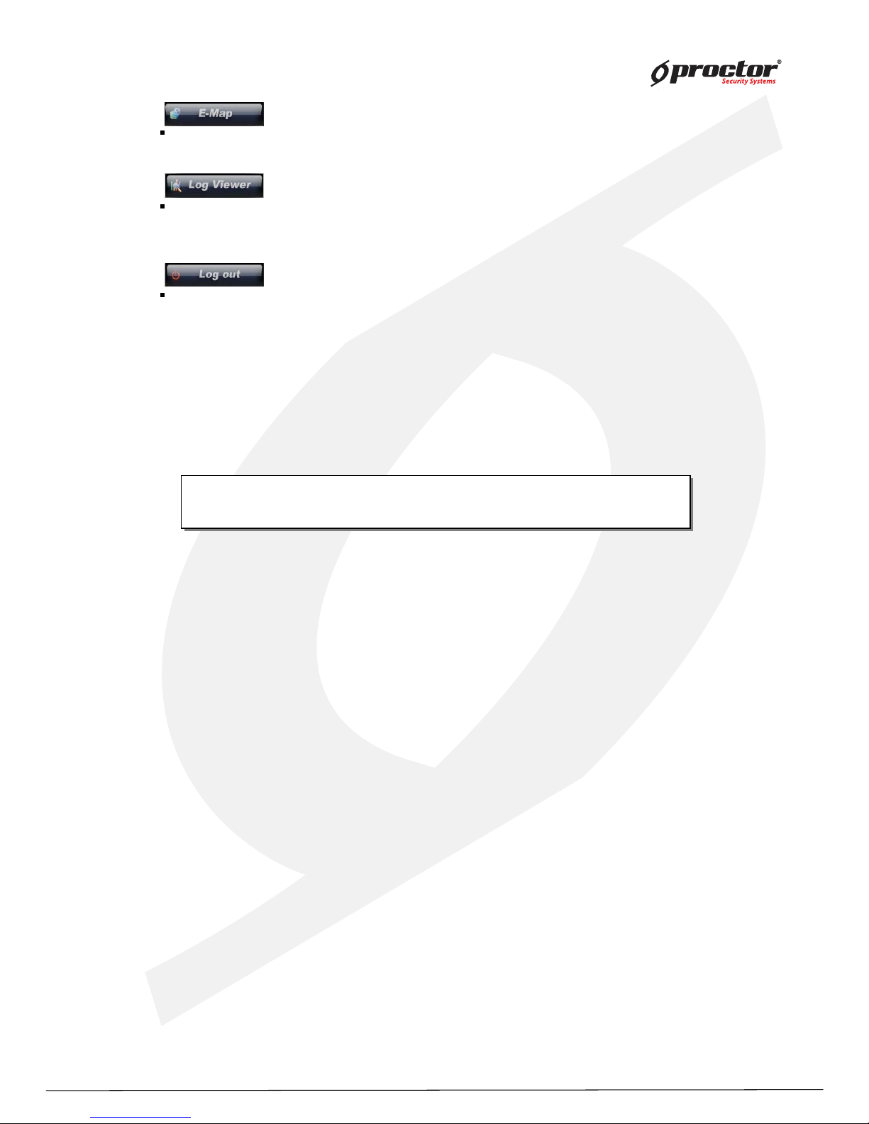
Logout : log in or out, shutdown, EMC Standby , cancel the program.
E-Map : Monitor the position of DVR, Camera, Sensor, and Control through E-MAP.
Default User ID : administrator / Password : 1234
Ask administrator or dealer if you forgot ID or PW.
Default User ID : administrator / Password : 1234
Ask administrator or dealer if you forgot ID or PW.
Log Viewer : Check ‘Log file’ in the CMS system by clicking the
button.
Page 84
Standalone DVR
7 9
Page:
User Manual Ver. 2.2
Display Mode
Setup Mode
Search mode
C M S – S etup M o de
Page 85
Standalone DVR
8 0
Page:
User Manual Ver. 2.2
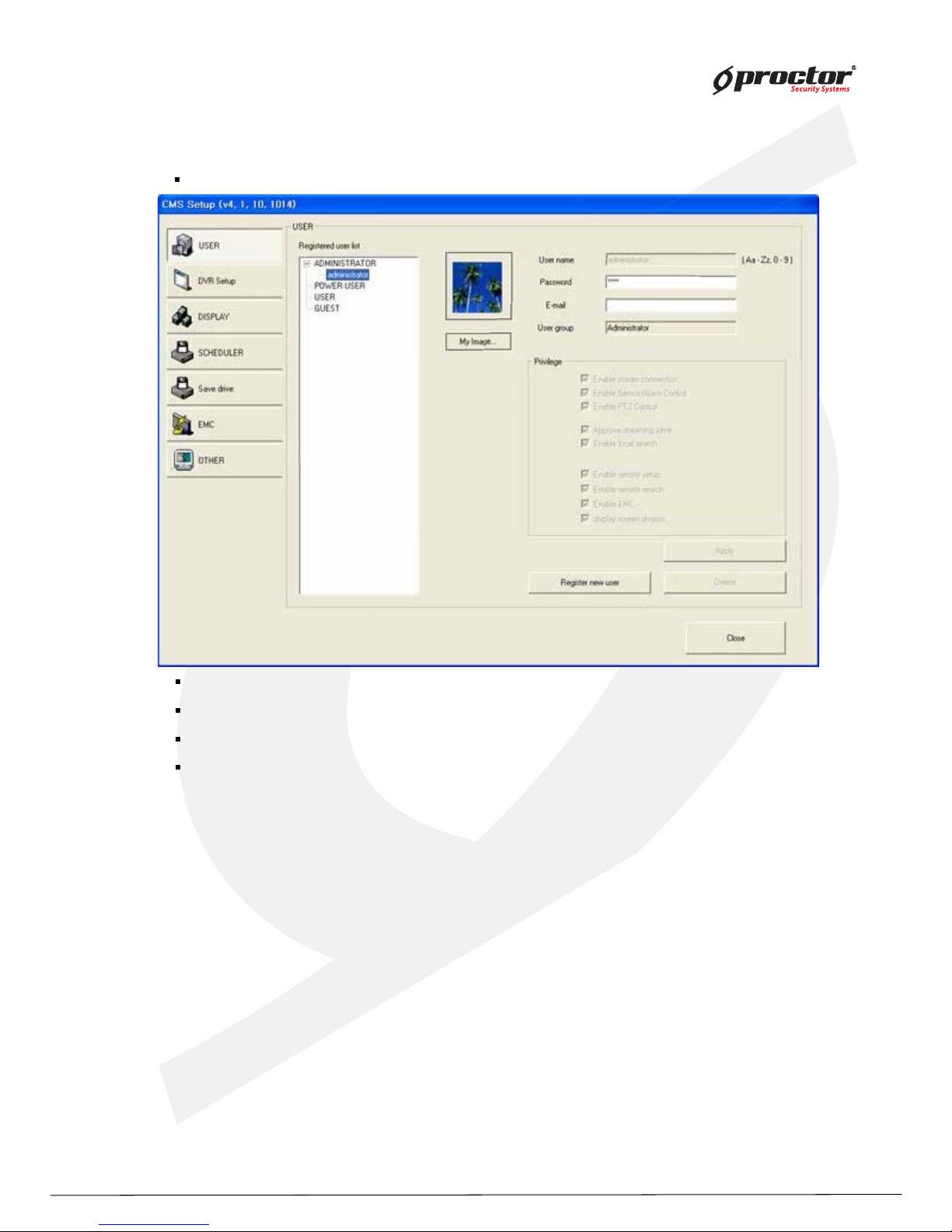
USER : make the user group with different privilege. Default is ‘ADMINISTRATOR’ .
Reg istered user list : It represents the group of registered users.
Reg ister new user : Register new user : click this button to add new user, and click ‘ Apply’ .
Privileg e : you can assign different privilege to each user.
My imag e : change the image with that you prefer such as company logo.
Setup
Page 86
Standalone DVR
8 1
Page:
User Manual Ver. 2.2
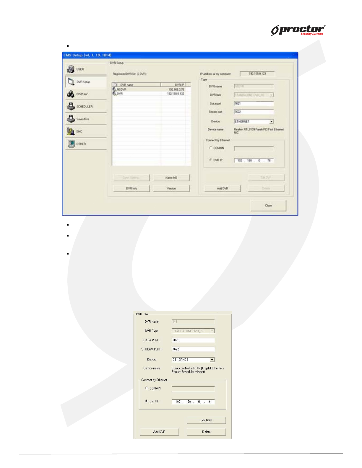
DVR Setup : setup the network connection.
Reg istered site list : It represents registered DVR LIST.
IP address of my computer : It represents IP information of CMS
System.
DVR Info : Input the information of Network connection as DVR is
registered.
Add site : Input Site name, DVR Type, PORT, and Site IP.
Page 87
Standalone DVR
82
Page:
User Manual Ver. 2.2
Delete : click it to remove the registered site.
Edit site : edit setup information.
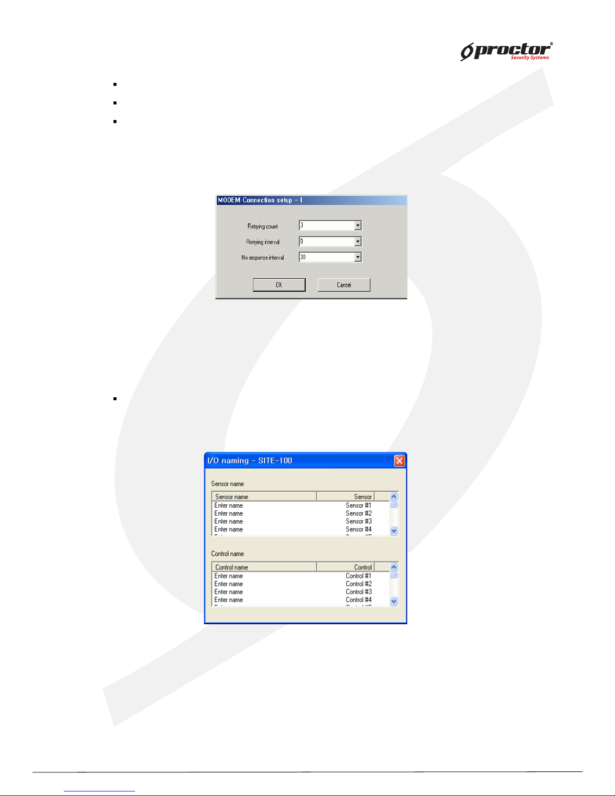
Conn. Setting : it is for modem connection setup. You should setup Modem on OS, and this
button will be enabled. Adjust the time for retrying connection. If there is no
response from the site system, the system will retry connection as you set up.
Name I/O : you can change the name of sensor and control. Double click ‘Enter name’, and it
will be enabled to put the name.
Page 88
Standalone DVR
83
Page:
User Manual Ver. 2.2
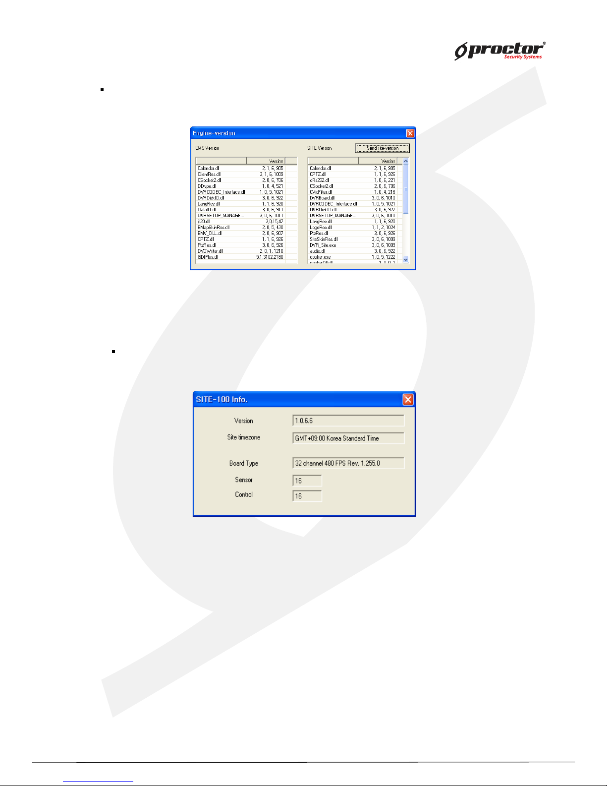
Show versions : shows the version of CMS currently using, click ‘Send site version’ to show
the information of site version.
DVR Info.: shows the information of connecting site, program version, time, capture card
type, the number of sensor and control.
Page 89
Standalone DVR
8 4
Page:
User Manual Ver. 2.2
Display
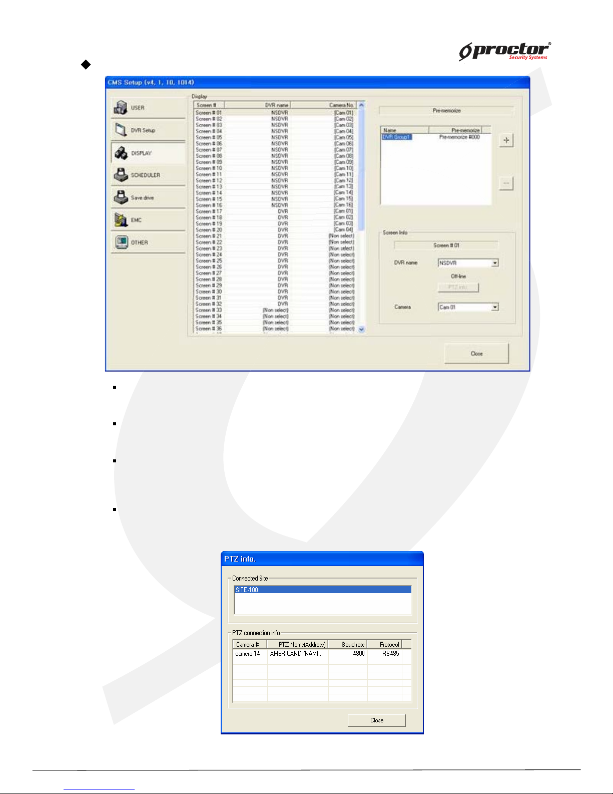
DISPLAY : It represents CMS DISPLAY SCREEN and setup information on the LIST.
Setup Pre-Memoriz e : Display list can be generated by clicking “ + ” and “ - ” after setup display.
SCREEN Info : Select DVR name and camera after selecting Display List to monitor the
appropriate image.
PTZ info Check the information of PTZ setup of each DVR.
Page 90
Standalone DVR
85
Page:
User Manual Ver. 2.2
SCHDULER
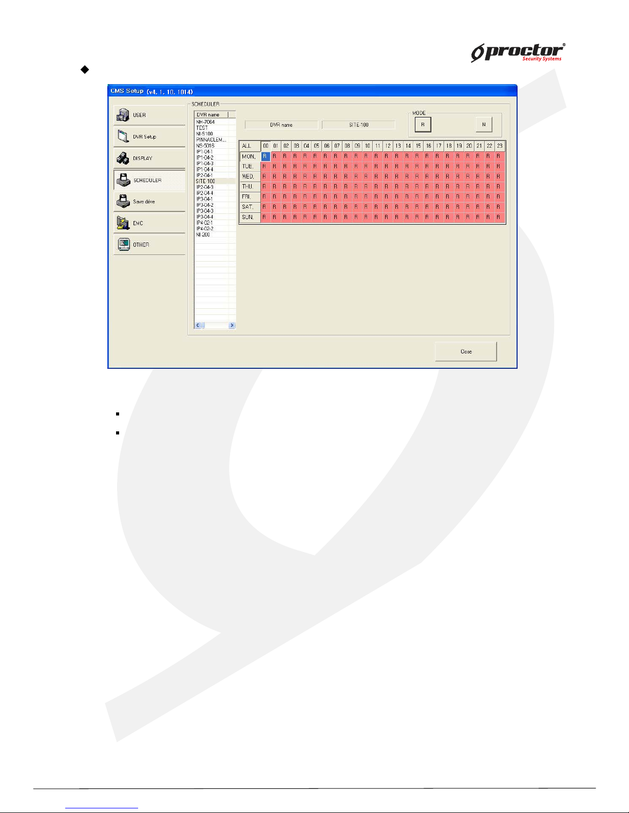
DVR list : shows a list of registered DVR.
Recording Schedule : setup save schedule for the selected DVR from the DVR
- Select DVR to save from DVR List.
- Drag or click to select the date/time to change the schedule.
- Click ‘R’ (Recording), ‘N’ (Not Recording) buttons to change the schedule.
Page 91
Standalone DVR
86
Page:
User Manual Ver. 2.2
SAVE DISK
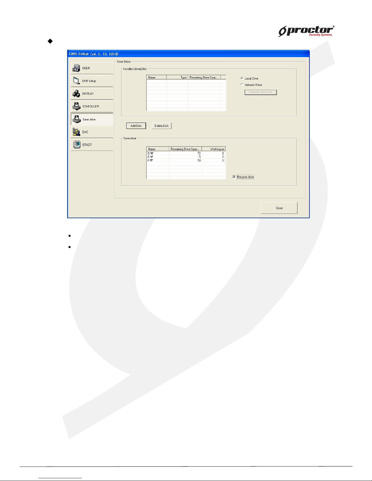
Install drive(s) list: shows a drive list of CMS system.
Save drive: shows the list of drives to DVR data, transmitted to CMS.
Setting up ‘Local Drive’
1) Select a drive to save data from ‘Installed drive(s) list’
2) Click ‘Add Disk’ button to add it as ‘Save drive’.
you can use ‘Recycle drive’ function when you added more than 2 drives.
Setting up ‘Network Drive’
1) Checkmark ‘Network Drive’ and click ‘Network Drive Add’ button.
2) ‘Network Drive’ will be generated. Then, Click ‘Add Disk’ button to add it as ‘Save drive’
from the list.
You cannot use ‘Recycle drive’ function.
Page 92
Standalone DVR
8 7
Page:
User Manual Ver. 2.2
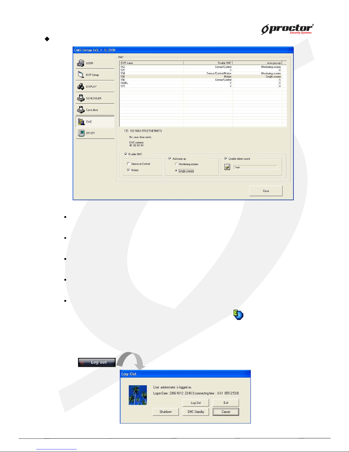
EMC (Emergency Management Center)
EMC mode : when the emergency event happen on the site, the event image is sent to CMS
system automatically with multiple or single screen.
Enable EMC : checkmark to enable EMC. Select the event mode either by motion or by sensor
or control.
Auto pop-up : when EMC is activated by motion or sensor/control, the event will come up with
monitoring screen or single screen.
Enable alarm sound : checkmark to enable alarm sound when EMC is activated. Open the
folder and select wave file.
EMC activation : after setup is completed, go to monitoring mode. Click ‘ log out’ button, and you
can see ‘ EMC standby’ button. Select it, it will go to EMC mode. EMC icon will
be generated on the right corner of the bottom.
W hen EMC mode is activated by motion or sensor/control, the event screen
will automatically pop- up, and the icon will be turn in red.
Page 93
Standalone DVR
88
Page:
User Manual Ver. 2.2
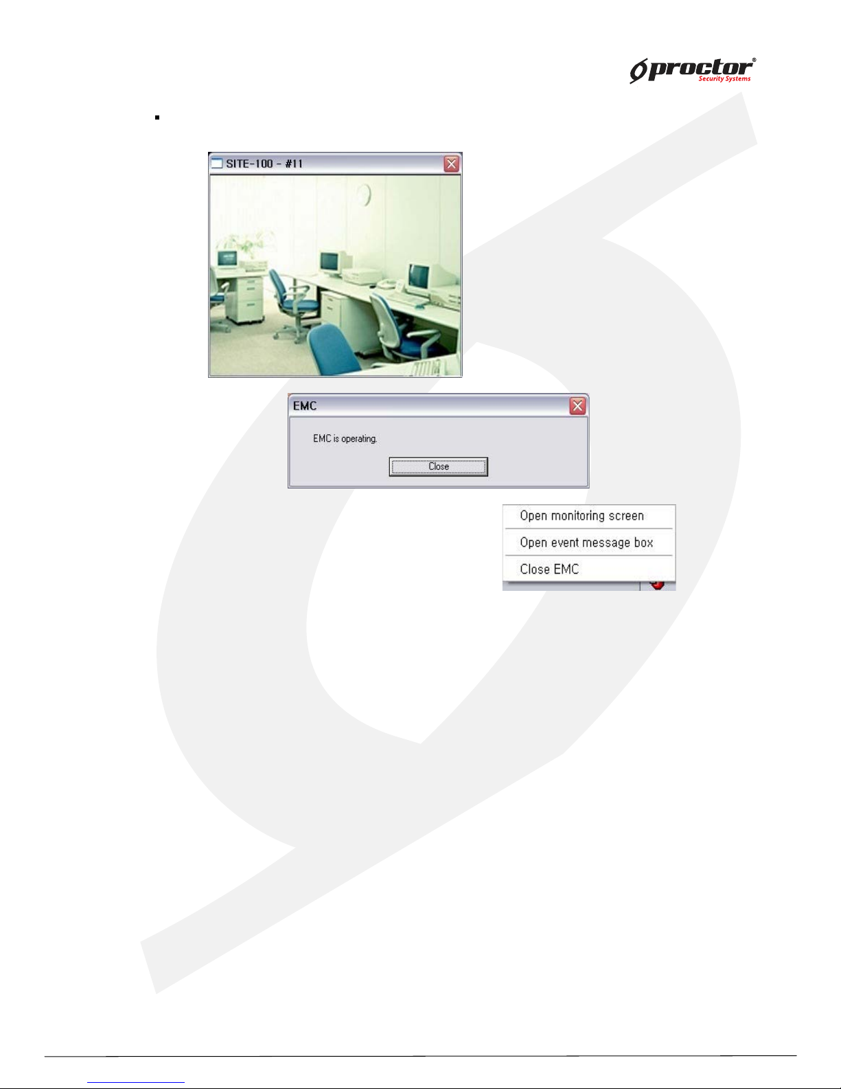
EMC single screen pop-up : automatically pop up with site name and camera number.
Page 94
Standalone DVR
8 9
Page:
User Manual Ver. 2.2
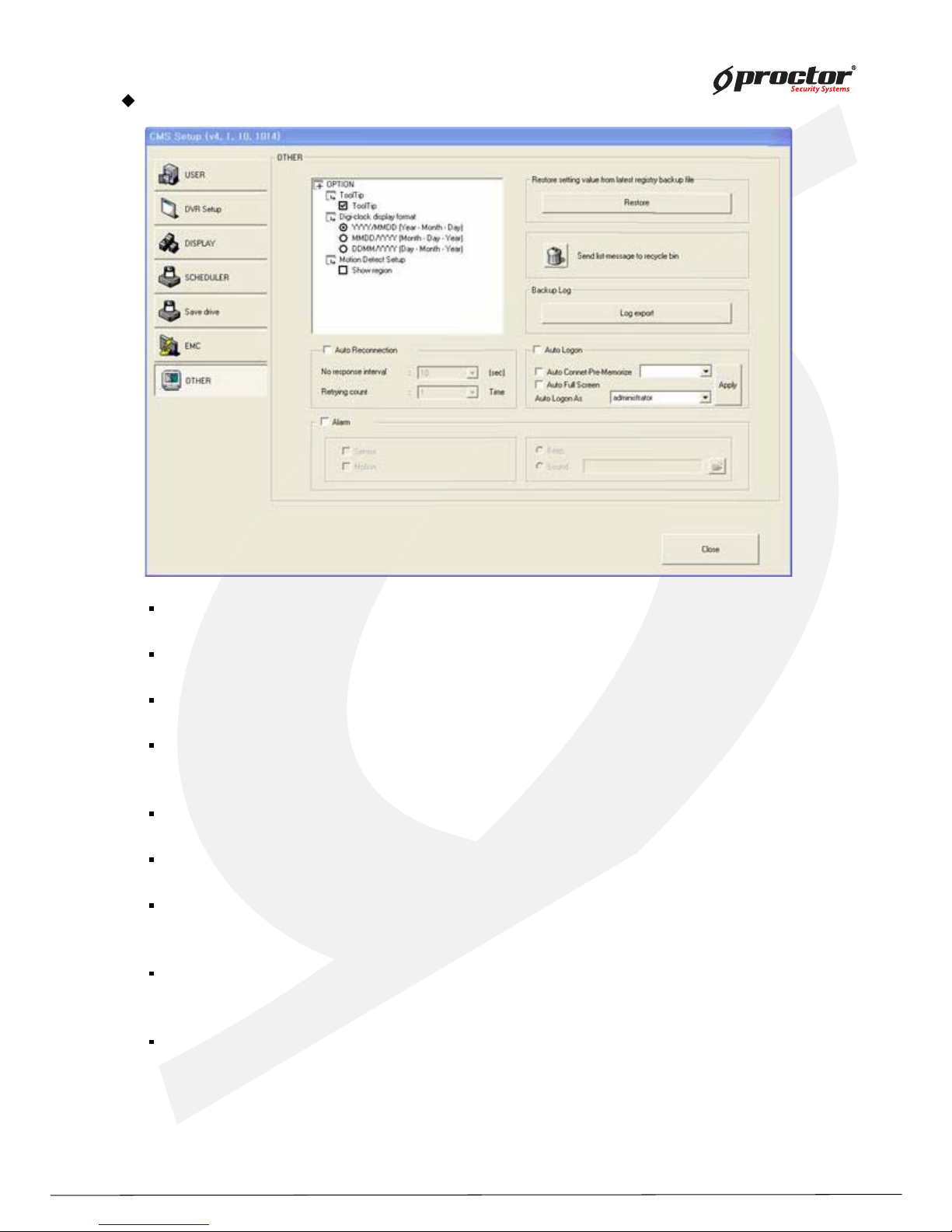
Setting up OTHERS
Tool Tip : shows function ex planation if you put the mouse on the function key.
Dig i-Clock display format : select display format of digit al- clock.
Motion Detection Setup: shows the motion detected area if the transmitted dada is motion Event.
Restore : in case of system shutdown, changes in system setting value or other functions,
you can restore the latest setting value.
Send list-messag e board to recy cle bin : send the all messages on ‘ Message board’ to recycle bin.
Log ex port : shutdown all the generated log files.
Auto reconnection : if network is unstable and disconnect for a period of time, CMS retry connection
with site system. Adjust waiting time and retrial count.
Auto Log on : Connect to Pre-Memorize data automatically when user Log in on CMS.
(Log in account must be selected)
Alarm : Beep out or specified wav file output when sensor or motion detected.
Page 95
Standalone DVR
9 0
Page:
User Manual Ver. 2.2
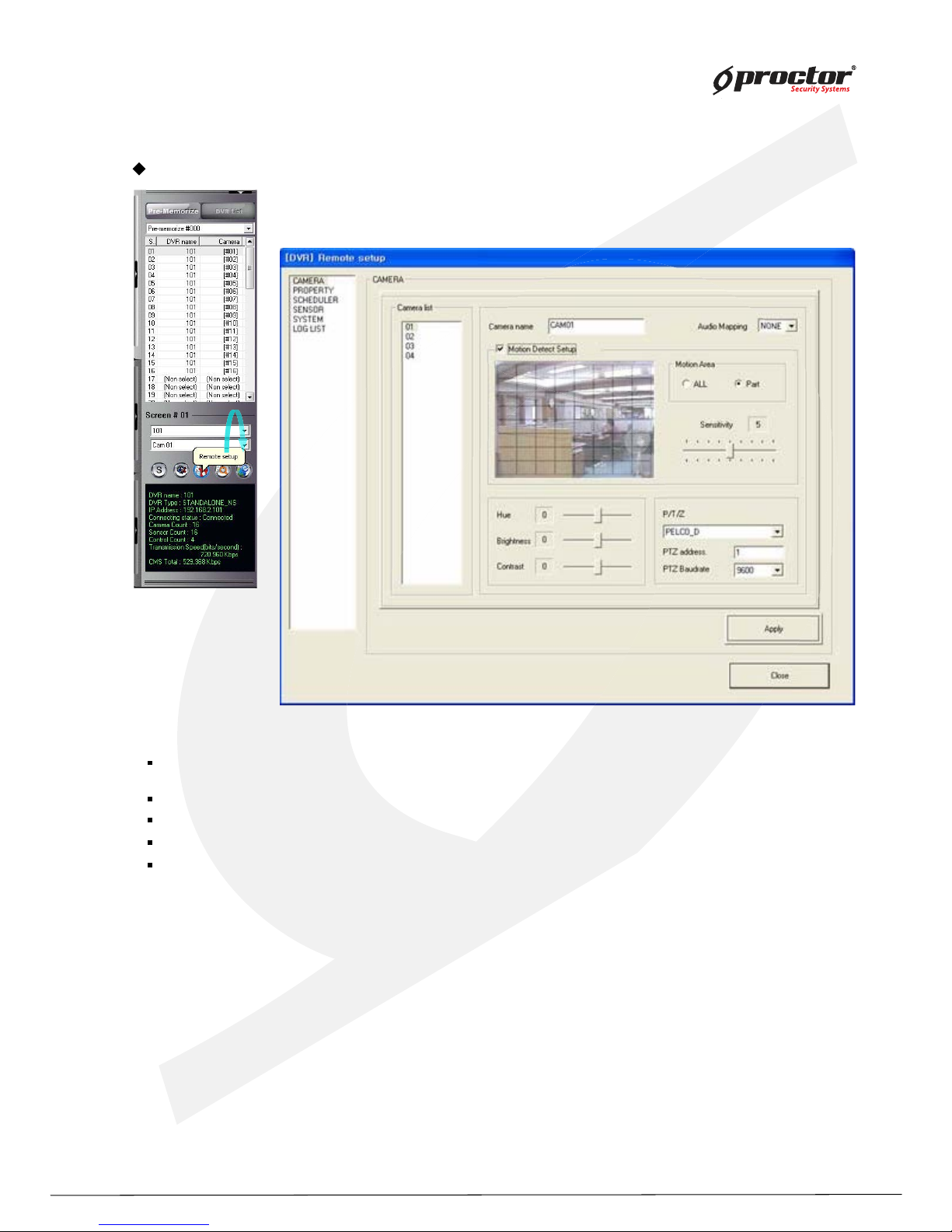
Remote Setup
Camera list : shows camera list installed on the site, and you can make the setup on the network.
Select a camera to setup.
Camera name : change the camera name, and adj ust color, brightness, contrast of the camera.
Use Motion : select the full or part of motion area, and also control motion sensitivity.
Color : control color, bright, and contrast.
Use PTZ : select PTZ and put the address and PTZ Baudrate.
Camera
Page 96
Standalone DVR
9 1
Page:
User Manual Ver. 2.2
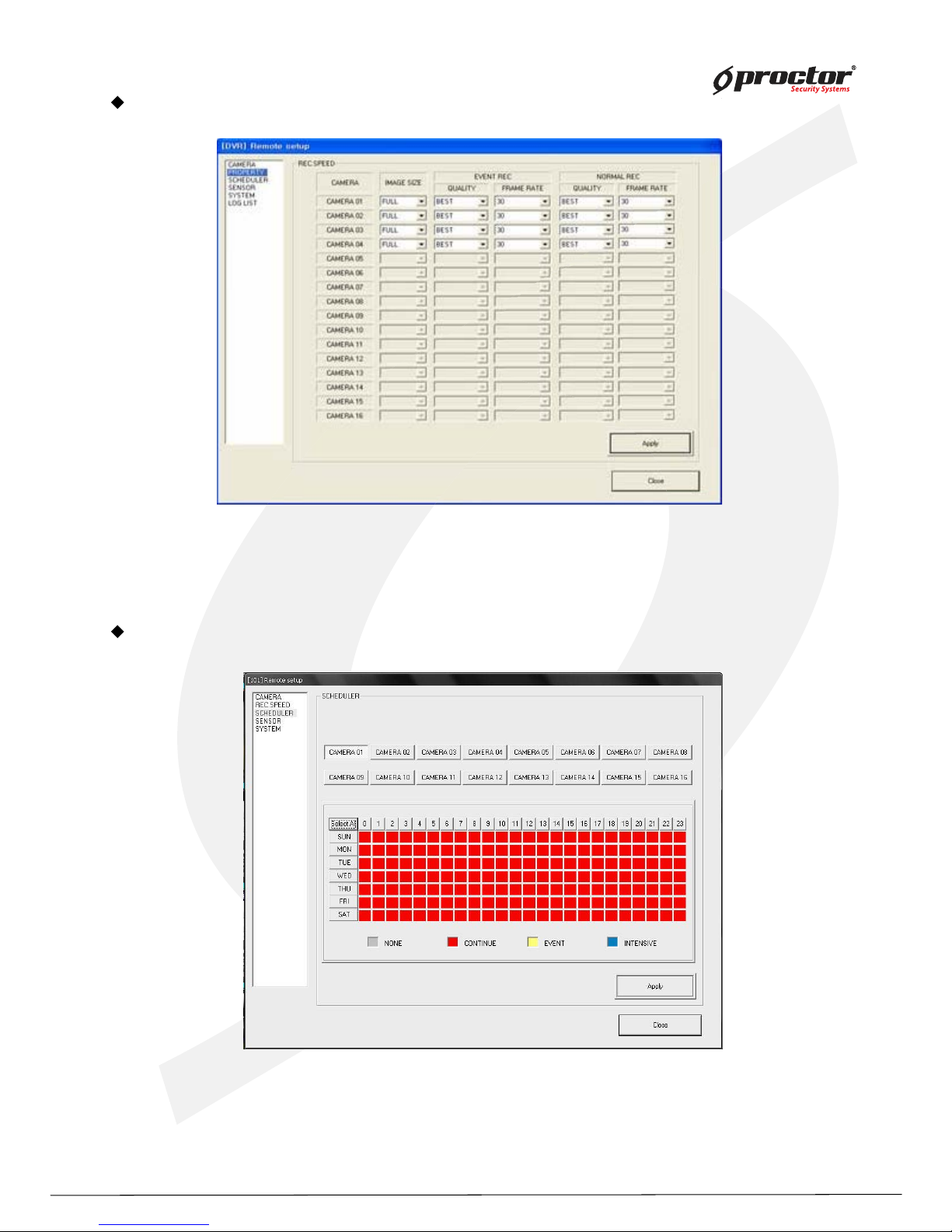
Record speed
1 ) Image siz e : select image siz e for recording.
(EVENT REC / NORMAL REC)
2) Individual camera recording setup : select image siz e, q uality, frame rates for each camera.
SCHEDULER
1 ) Recording schedule : select a date of a week, and setup recording schedule. Selected value will be
shown in red mark. Click ‘ All’ to apply the same setup for all cameras.
Page 97
Standalone DVR
9 2
Page:
User Manual Ver. 2.2
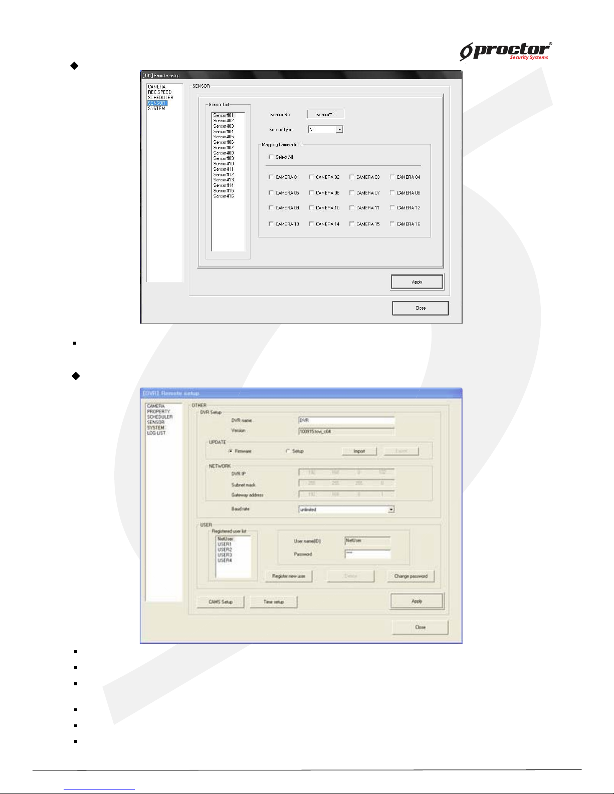
Map sensors to cameras, and select the sensor type.
SENSOR
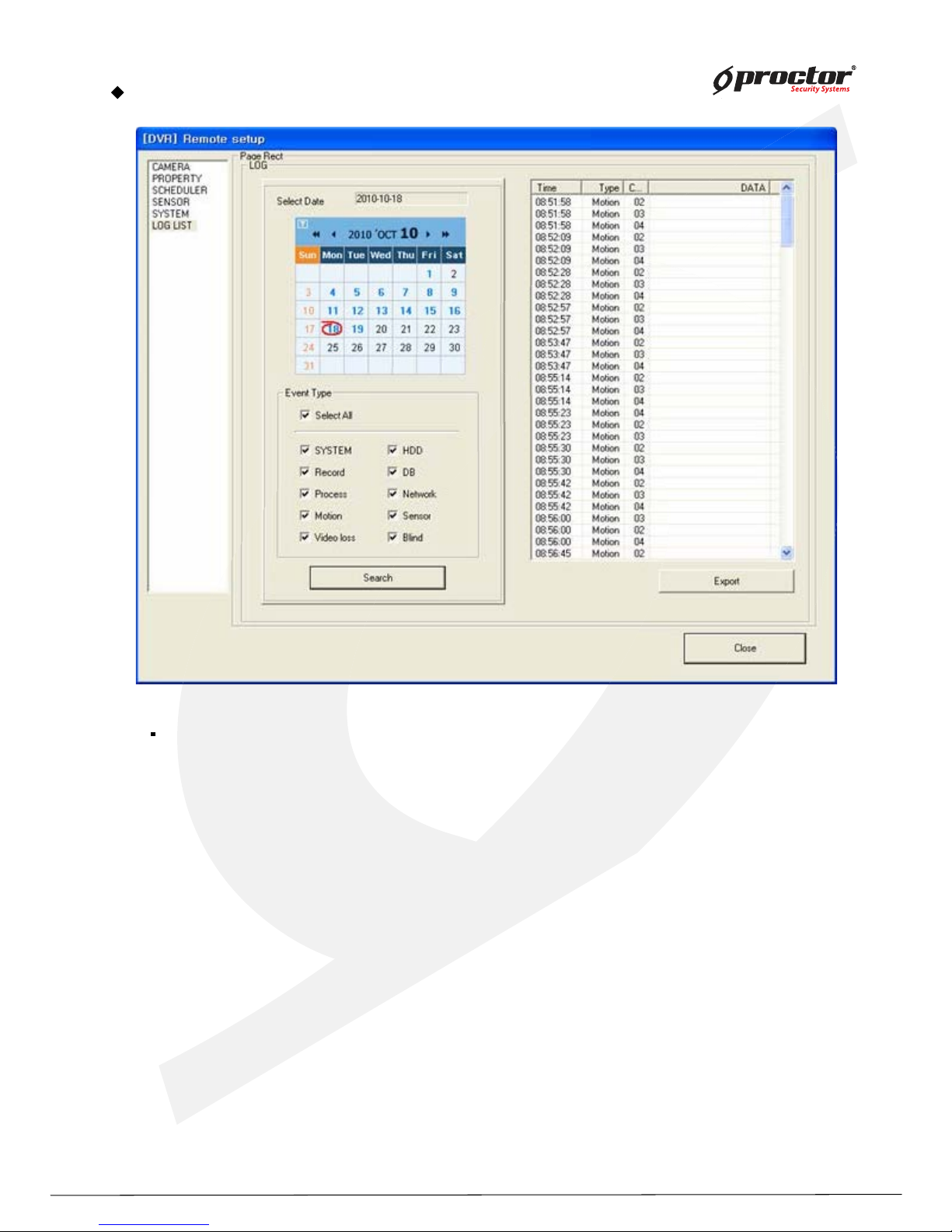
SY STEM
DVR info : shows the connected DVR information such as DVR name, program version.
Network info : shows network connection information such as IP address, subnet mask, gateway.
User info : shows user list of the connected DVR. Y ou can change password, register new user,
and delete user.
Network Transmission Speed : Setup Network transmission speed.
CAMS Setup : setup for CAMS monitoring.
Time setup : setup for DVR time (Manual input – input the time manually.
Client time setup – synchroniz e the DVR time to CMS server time)
Page 98
Standalone DVR
9 3
Page:
User Manual Ver. 2.2
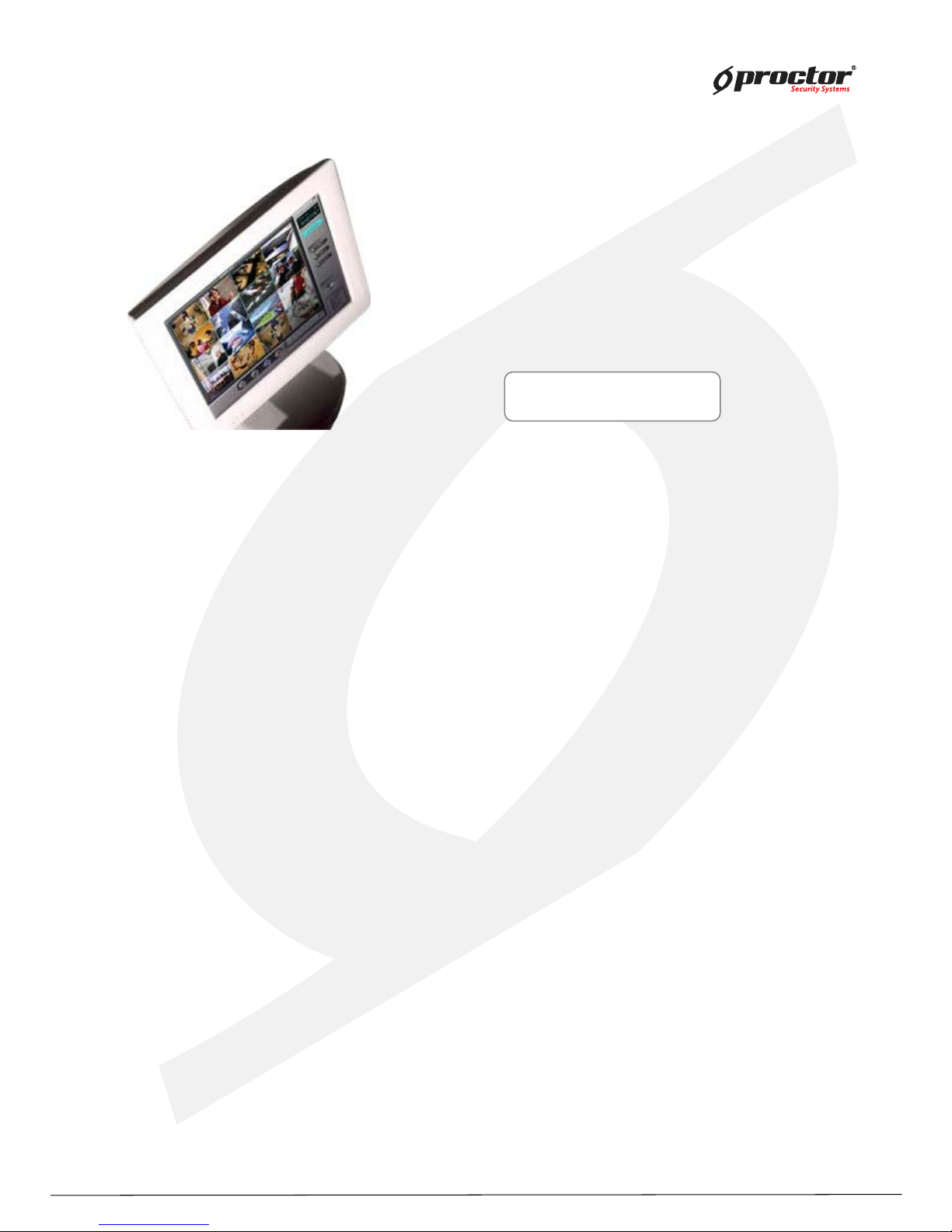
LOG LIST
LOG LIST : search for DVR event log.
(System, H DD, Record, DB, Process, Network, Motion, Sensor, V- loss, Blind)
- Select data on the calendar.
- Select event type and click “ Search” button.
- Event search result will show up on log list window on the right side.
Page 99
Standalone DVR
9 4
Page:
User Manual Ver. 2.2
C M S – S ear c h M o de
Display Mode
Setup Mode
Search mode
Page 100
Standalone DVR
9 5
Page:
User Manual Ver. 2.2
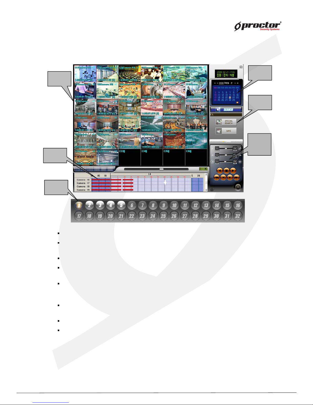
Search Mode
Play back screen : displays playback image of the screen.
Dig i-clock / Calendar : digi- clock shows current system time. The date whic h has save data is
shown with different color. Select the date to search, and then, system will start to load data.
Search : select a folder to search data.
Time table : after data loading is completed, the data save location will be shown on the time
table. Y ou can select camera and time to playback.
Sy stem Utility buttons : access to ‘ Special Search’ and ‘ Save’ function. ‘Special Search’
provides ‘real player’ , ‘multi time player’ , ‘ day search’ , ‘ obj ect search’ . Click ‘ OPEN’ , it provides
more search conditions. Therefore, you can do more detailed search effectively.
Screen division/Play back scroll : it provides various screen divisions, and ‘ playback scroll’
shows the progress of data playback.
Audio play back speak er : playback Audio data.
Camera number : when you use ‘ special search’, this camera number bar will show up. Click
any camera you want to playback.
Time table
Time table
Time table
Screen
Division
Play back
Scroll
Screen
Screen
Division
Division
Play back
Play back
Scroll
Scroll
Sy stem
Utility
Sy stem
Sy stem
Utility
Utility
Play back
Screen
Play back
Play back
Screen
Screen
Dig i-clock
Calendar
Dig i
Dig i--
clock
clock
Calendar
Calendar
Camera
Camera
Camera
 Loading...