

OOPPEERRAATTIINNGG IINNSSTTRRUUCCTTIIOONNSS FFOORR
SSOOLLDDEERRIINNGG MMAACCHHIINNEE
No. 54.050 (115 Volt)
No. 54.050X (220 Volt)
The PRO-CRAFT soldering machine is designed to operate on 115 or 220 volts, 60 cycle AC current. A 15 ampere
circuit is ample, provided the line is not overloaded with other equipment. After connecting the machine to a wall outlet, step on the foot switch. A buzzing sound will indicate the machine is receiving current and is ready for use.
The PRO-CRAFT soldering machine is shockproof! Those unfamiliar with electric soldering must overcome any fear
of shock. The voltage at the highest heat is very low and your hands may touch any part of the carbon holders or
contact clips without sensation of shock.
The heat for soldering is produced electrically, without flame, by touching a carbon electrode to the work to be soldered. The current passing through the carbon will heat the object to be soldered in a matter of seconds.
SOLDERING SUGGESTIONS
Many jobs which are difficult or impossible with a flame can be easily accomplished. Heat is generated quickly and is
focused at the point of contact.
If the crystallized flux breaks the contact while soldering, move the work to another spot on the carbon or scrape the
flux from the article when it makes contact. A piece of emery cloth or a file attached to the top of the bench is very useful for removing flux from the article and the carbons. Do not increase the heat if contact is broken, as this can result in
ruined work.
FAMILIARIZE YOURSELF WITH THE MACHINE AND ACCESSORIES
The carbon holder stand is for the tapered carbon. It is plugged into the red cord. The carbon holder stand can be
adjusted to use the carbon both horizontally and vertically. It is made low enough so that both hands can rest on the
bench to steady them while soldering.
Two sizes of spring contact clips are supplied. One or the other is plugged into the black cord. These are used to hold
the article to be soldered. Use the large clip whenever possible.
Heat is controlled by the indicator knob. The amount of heat required depends on the type of solder and the area to be
soldered. Some experimentation will soon enable you to judge which heat setting will be required.
The foot switch turns the machine on and off. As an extra precaution, we recommend disconnecting the machine from
the electrical outlet when you are through with your work.
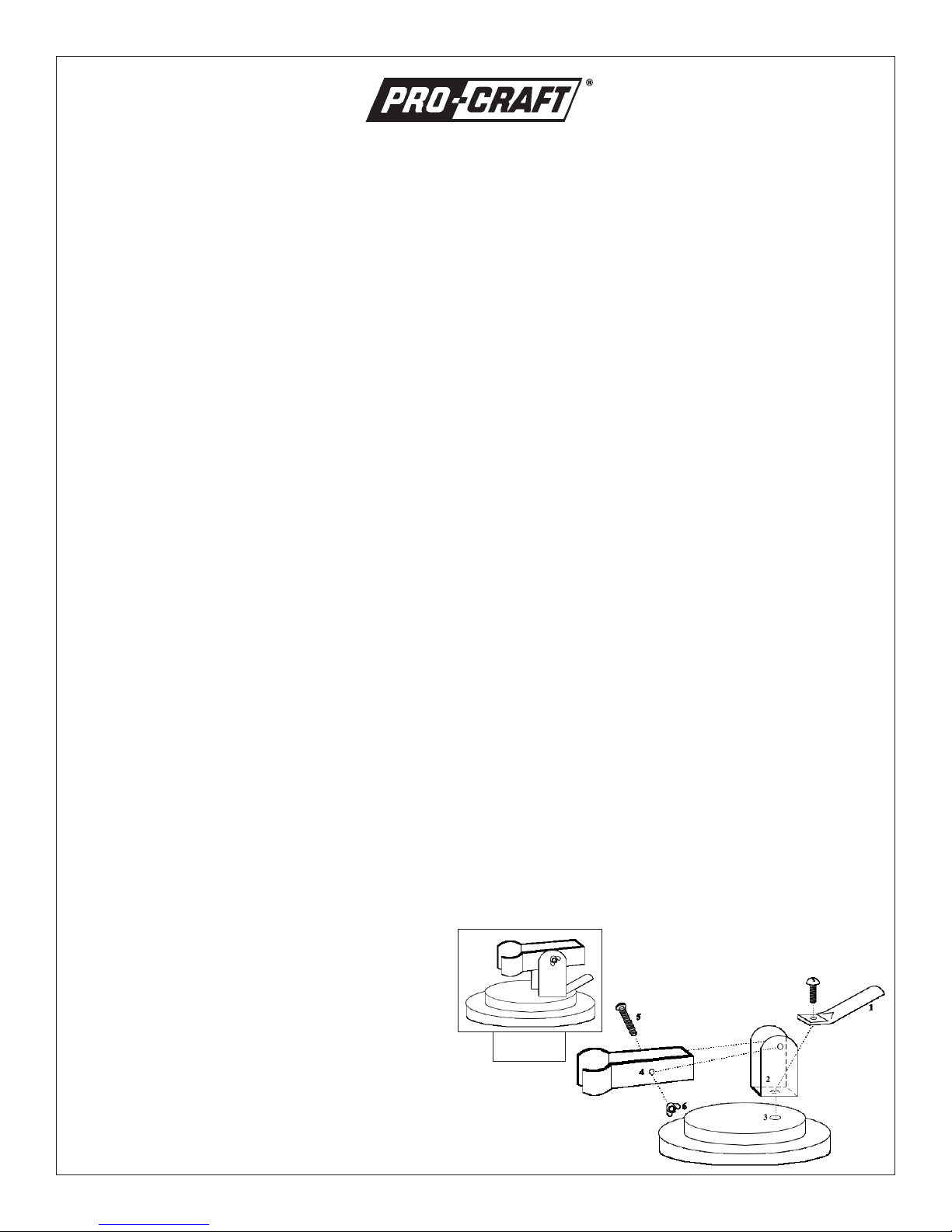
TO ASSEMBLE THE CARBON STAND
1. The smaller screw assembles the tubing connector
(1) and the upright clamp (2) to the base (3). The
screw goes into the threaded hole in the base to
hold the parts securely.
2. The carbon holder (4) is placed within the arms of
the upright clamp, the holes are lined up and the
longer screw (5) is passed through the holes.
3. The wing nut (6) is screwed onto the long screw to
hold the parts in place.
4. The carbon is placed within the rounded portion of
the carbon holder and positioned at the desired
angle. The wing nut is tightened to hold the
parts securely.
GROBET USA®Carlstadt, New Jersey 07072
Assembled
Carbon Stand
IS54.050

SOLDERING PROCEDURE
efore trying new work, practice on old articles from the scrap box to familiarize yourself with the general procedures.
B
1. Clean work by immersing in an ultrasonic.
2. Arrange work so that hands can be held steady. The idea is to provide a complete electrical circuit, with the carbon
at the point to be soldered.
3. Attach contact clip to the article, as near as possible to the joint being soldered. If clips cannot be used, use point-
ed brass rod in the large clip to make contact. Adjust carbon so that you can conveniently touch the joint to be soldered. If two different size pieces are being joined, attach the contact clip to the larger piece.
4.
Place solder at the joint. Where two separate pieces are to be joined, it is usually preferable to place the solder
between them or directly under the joint. Placing solder on top of the work usually results in the solder forming a ball
and rolling away. It is sometimes convenient to “tack” the solder at low heat to one part before fusing the joint together.
5. Apply flux to solder as well as joint to be soldered. Keep flux away from carbon as much as possible.
6. The heat control should be set to the correct setting. If you are not sure of the setting, set the control in the middle.
Remember that a small point of contact will create intense heat. After a little practice you will be able to determine
the exact settings for different jobs and metals.
7. Bring the joint to be soldered in contact with the carbon and hold steady. Avoid using undue pressure, as flat spots
or deformation may occur. Apply the heat by stepping on the floor switch.
8. If the solder flows immediately (within 3 seconds), release the foot switch before removing the work from the carbon.
If the solder does not flow immediately, clean all components and start again. If the heat control was initially set too
high, the joint might burn. It is possible for the quick, intense heat to oxidize the joint, thereby destroying the electrical contact. Examine the article carefully for discoloration caused by oxidation. If discolored, start over again, cleaning the article and solder thoroughly.
9. To establish a complete circuit, all components must be free of contamination. File carbon as well as articles to be
joined.
FLUXES
Because most metals oxidize when heated, a flux must be used to dissolve the oxides. Oxides prevent solder from
adhering and flowing. The flux also acts as a protective film to keep the air away from the metal, thus checking oxidation.
Oxides formed by hard metal alloys are different from those formed in softer metals. Fluxes are compounded especially for the metals and alloys which will be used in each soldering process. Furthermore, fluxes must withstand the temperature used in each process. Selection of the correct type of flux is important. Various fluxes are listed in our catalog,
along with recommendations for use.
SOLDERS
The type selected must melt at a lower temperature than the pieces being joined or the work will melt before the solder.
The solder must bond with the metals being joined. Generally, metals which can be alloyed with the work should be present in the solder. It is often important that the joints be invisible and the color of the solder should match the original
piece. It is for this reason that there is a gold solder to match almost every color and karat of gold.
CLEANLINESS
To form a strong bond, the solders and metals to be joined must be clean. Scratch brush and scrape the area to be soldered so that it is visually clean and bright. If piece heats and solder does not flow, clean and start again.
Carbons should also be kept clean by using coarse emery cloths, leaving the surface somewhat rough. A quick wipe
with a moist cloth after every soldering will prevent a build-up of foreign matter, for better contact.
PACKING LIST
This machine has been carefully packaged with the following items. Please check carefully before discarding any packaging material.
Tapered Carbon 54.054 Pencil Carbon 54.056
Alligator Clip 54.059 Cylindrical Carbon 54.057
Clamp with Lug 54.060 Cylindrical Flat Carbon 54.058
Carbon Holder and Base 54.064 Small Pencil Carbon (2 pieces) 54.055
Contact Rod 54.063
Carbon holder and base includes the following parts: cast iron base, 2 round head machine screws, wing nut, U-bracket, carbon
bracket, tubing connector and directions for assembling.
Unit No.: Packaged by:
GROBET USA®Carlstadt, New Jersey 07072
 Loading...