

Page 1
Pro.rfz
Quick Reference Guide
WIRELESS RANGE EXTENDER
Safety Suggestions
Read and Follow Instructions. Read all safety and operating instructions before
operating the unit.
Retain Instructions. Keep the safety and operating instructions for future
reference.
Heed Warnings. Adhere to all warnings on the unit and in the operating
instructions.
Heat. Keep the unit away from heat sources such as radiators, heat registers,
stoves, etc., including ampliers that produce heat.
Power Sources. Use only power sources of the type described in the operating
instructions, or as marked on the unit.
Water and Moisture. Do not use the unit near water—for example, near a sink,
in a wet basement, near a swimming pool, near an open window, etc.
Object and Liquid Entry. Do not allow objects to fall or liquids to be spilled into
the enclosure through openings.
Servicing. Do not attempt any service beyond that described in the operating
instructions. Refer all other service needs to qualied service personnel.
Damage Requiring Service. The unit should be serviced by qualied service
personnel when:
Objects have fallen or liquid has been spilled into the unit.
The unit has been exposed to rain.
The unit does not appear to operate normally or exhibits a marked change
in performance.
The unit has been dropped or the enclosure has been damaged.
Limited Warranty
Pro Control warrants its products for a period of one (1) year (90 days only for
included battery packs); or for a period of time compliant with local laws when
applicable from the date of purchase from Pro Control or an authorized Pro
Control distributor.
This warranty may be enforced by the original purchaser and subsequent owners
during the warranty period, so long as the original dated sales receipt or other
proof of warranty coverage is presented when warranty service is required.
Except as specied below, this warranty covers all defects in material and
workmanship in this product. The following are not covered by the warranty:
Damage resulting from:
1. Accident, misuse, abuse, or neglect.
2. Failure to follow instructions contained in this Guide.
3. Repair or attempted repair by anyone other than Remote Technologies
Incorporated.
4. Failure to perform recommended periodic maintenance.
5. Causes other than product defects, including lack of skill, competence or
experience of user.
6. Shipment of this product (claims must be made to the carrier).
7. Being altered or which the serial number has been defaced, modied or
removed.
71-500012-16 V1.0
Pro Control is a division of Remote Technologies Inc. For information on how to
become a trained and authorized Pro Control Dealer, access to the Pro Control
Studio programming software, product information and more, please visit our
web site at: www.procontrol.com
For general information, you can contact Pro Control at:
Pro Control
5775 12th Ave. E Suite 180
Shakopee, MN 55379
Tel. (952) 224-5024
Fax (952) 253-3131
Sales
952-224-5010
Email: [email protected]
Customer Service
952-224-5020
Email: [email protected]
Technical Support
952-224-5024
Email: [email protected]
Contacting Pro Control
If you are encountering any problems or have a question about your Pro Control
product, please contact Pro Control Technical Support for assistance.
Pro Control provides technical support by telephone, fax or e-mail. For the
highest quality service, please have the following information ready, or provide it
in your fax or e-mail.
• Your Name
• Company Name
• Telephone Number
• E-mail Address
• Product model and serial number (if applicable)
If you are having a problem with hardware, please note the equipment in your
system, a description of the problem, and any troubleshooting you have already
tried.
If you are having a problem with software, please note what version you have
installed, the operating system on your PC, a description of the problem, and
any troubleshooting you have already tried. If you are calling about a software
or programming question or problem, please be at you computer when you place
your call. This will considerably speed up the troubleshooting process.
Please do not return products to Pro Control without return
authorization.
Service & Support
This equipment has been tested and found to comply with the limits for a Class
B digital device, pursuant to Part 15 of the FCC Rules. These limits are designed
to provide reasonable protection against harmful interference in a residential
installation. Any changes or modications not expressly approved by the party
responsible for compliance could void the user’s authority to operate the device.
This equipment generates, uses, and can radiate radio frequency energy and, if
not installed and used in accordance with the instructions, may cause harmful
interference to radio communications. However, there is no guarantee that
interference will not occur in a particular installation.
If this equipment does cause harmful interference to radio or television
reception, which can be determined by turning the equipment off and on, the
user is encouraged to try to correct the interference by one or more of the
following measures:
Reorient or relocate the receiving antenna.
Increase the separation between the equipment and the receiver.
Connect the equipment into an outlet on a circuit different from that to
which the receiver is connected.
Consult the dealer or an experienced radio/TV technician for help.
This device complies with Part 15 of the FCC Rules. Operation is subject to the
following two conditions:
1. This device may not cause harmful interference.
2. This device must accept any interference received including interference
that may cause undesired operation.
N27917
Federal Communications Commission Notice
Pro.rfz
WIRELESS RANGE EXTENDER
Get more control
®
P RO C O NTROL
Copyright © 2013 • Pro Control Incorporated • All rights reserved.
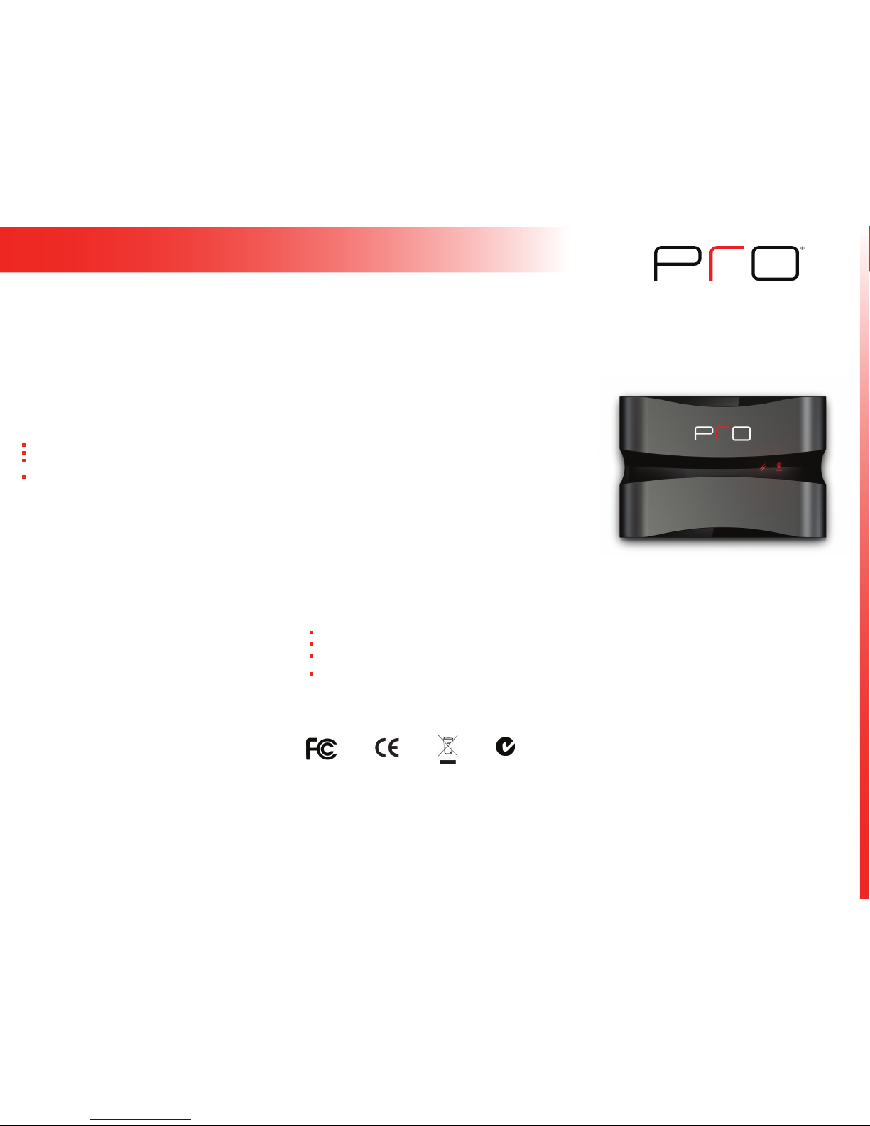
Extend the 2-way link between the ProLink.z processor and
Pro24.z remote, providing reliable control and feedback such
as song meta-data, volume level, lighting control and more.
Multiple modules can be added by simply powering them from an
electrical outlet. The Pro.rfz units will then create a self-healing
wireless network which instantly adapts to changes or problems
with the communication path. A detachable wall mount bracket
makes for a clean and easy installation.
Key Features
• Extends the 2.4GHz ZigBee® wireless range of the ProLink.z
processor.
• Wireless range between ProLink.z and Pro.rfz modules up to 70
feet.
• Supports bi-directional communication, providing control and
feedback with the Pro24.z remote.
• Adding Pro.rfz modules creates a self-healing wireless 2.4GHz
ZigBee RF network.
• Congured via Pro Control Studio and a micro USB cable.
• Durable plastic enclosure with integrated antenna.
• 6’ (2m) Power supply included.
• Easy mounting with a detachable wall bracket.
Contains: FCC ID: MMURTI1300
Contains: IC (Canada): 3166A-RTI1300
Page 2
Get more control
®
Product Contents
Contents within the box include the following items:
• One (1) Pro.rfz assembly
• One (1) Mounting bracket and screws (four #6-32 3/4” athead screw)
• One (1) 5VDC/1A power supply
• One (1) Quick reference guide
IMPORTANT NOTE: Please visit the Pro Control website dealer section
for additional details on determining the best placement of the Pro.rfz. You
will also nd information on programming changes that are required to
allow the Pro24.z remote to “roam” between the ProLink.z and Pro.rfz.
For best results, ProLink.z processors and Pro.rfz modules should be
placed:
• At least 3 feet (1m) from electronic components and at least 8 feet
(2.5m) from 2.4GHz wireless RF devices such as WiFi
®
access points,
cordless phone systems, Bluetooth
®
devices etc.
• At least 4 feet (1.2m) off the oor, away from brick, stone or concrete
construction materials.
• Installations may have multiple Pro.rfz modules to extend range further.
As long as the Pro.rfz modules are within communication range of each
other, a ZigBee wireless network will be established.
Mounting
Powering the Pro.rfz
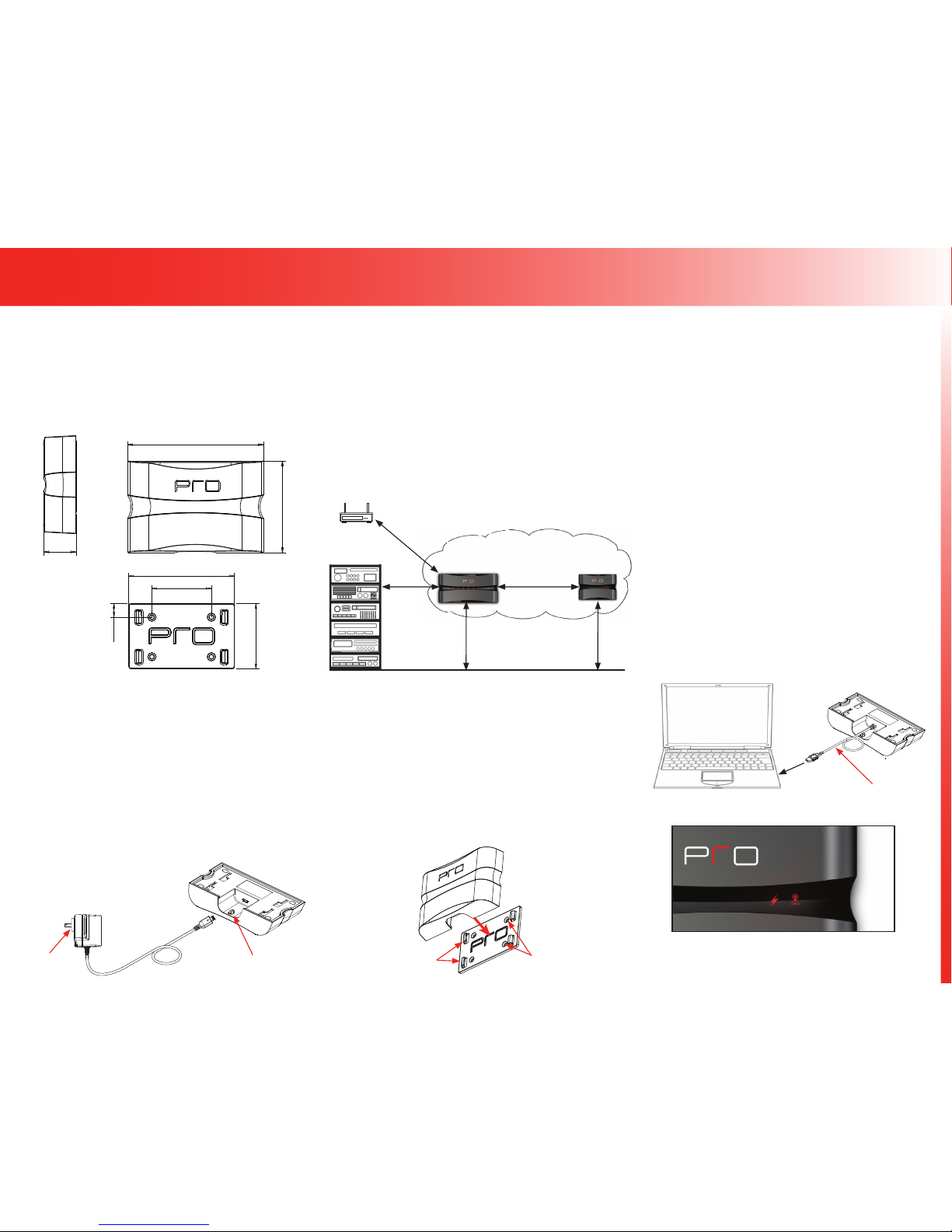
The Pro.rfz has a micro USB port located on the underside of the unit that
is used to power the Pro.rfz. In addition, the micro USB port is used to
download programming and rmware updates into the Pro.rfz from a PC
via a standard USB A to Micro B cable.
NOTE: The Pro.rfz CANNOT be wired/powered directly from a Pro Control
processor.
1. Install the appropriate wall outlet plug on to the included power supply
(5VDC/1Amp)
2. Connect the power supply micro USB connector to the Pro.rfz USB port.
3. Plug the power supply cable into a wall outlet.
4. The Pro.rfz power cable can be secured by using a zip-tie (not included)
looped through the zip-tie clip located on the underside of the Pro.rfz.
Pro.rfz
Pro.rfz Location
50 ft. - 70 ft.
(15m - 20m)
3 ft. (1m)
Minimum
Equipment Rack
4 ft. (1.2m) Minimum
Wireless
Access Point
8 ft. (2.5m)
Minimum
Programming the Pro.rfz
Please verify that you have the most recent rmware and software
installed for this and all Pro Control products. Authorized Pro Control
dealers can download the latest Pro Control Studio software from the
dealer section of www.procontrol.com.
NOTE: Downloading software/rmware updates to the Pro.rfz requires a
USB A to Micro B cable (not included).
Updating Pro.rfz Firmware:
Updating the Pro.rfz rmware takes place via the Pro Control Studio
software which includes the latest Pro Control product rmware updates.
Follow these steps to update the Pro.rfz rmware.
1. Verify that you have the latest version of Pro Control Studio software
installed.
2. Open the programming le in Pro Control Studio and add a Pro.rfz to
the ProLink.z as an “Expansion Device”.
3. Plug in the USB A to Micro B cable to the PC and the Pro.rfz USB port
(this also powers the Pro.rfz during the programming update).
4. Click the “Congure Device” button and double click on the Pro.rfz to
open the device conguration window.
5. If the “Firmware Version” displays a notication that a newer
rmware version is available, click on the “Update Firmware” button
to complete the update process.
Programming the Pro.rfz:
Each Pro.rfz that will be used with a ProLink.z processor must be
programmed using the Pro Control Studio software.
Follow these steps to program the Pro.rfz.
1. Open the programming le in Pro Control Studio and add a Pro.rfz to
the ProLink.z as an “Expansion Device”.
2. Plug in the USB A to Micro B cable to the PC and the Pro.rfz USB port
(this also powers the Pro.rfz during the programming update).
3. Click the “Congure Device” button and click on the Pro.rfz that needs
updating.
4. Click on “Download to Selected Device” to complete the programming
process.
ProLink.z Processor Pro.rfz
The Pro.rfz should be located on a secure, at surface, or mounted to a
wall, shelf, or cabinet using the enclosed mounting bracket.
NOTE: In addition to following the location instructions, when mounting
the Pro.rfz, be certain to choose a safe location (e.g. away from electrical
junction boxes, wiring, wet locations, etc.)
Mounting Bracket Installation
1. Level and anchor the mounting bracket to desired wall, shelf, or cabinet
by screwing appropriate fasteners (four #6-32 3/4” athead screws
included) through the mounting plate fastener holes.
2. Afx the Pro.rfz to the mounting plate by placing the channel locks
located on the rear of the unit over the channel lock clips located on
the front of the mounting plate. Slide the Pro.rfz down until the channel
lock clips lock into place.
ZigBee® Wireless Network
Mounting Bracket
Fastener Holes (x4)
Channel Lock Clips (x4)
USB A to Micro B Cable
PC
Pro.rfz (Underside)
Power Supply
5VDC/1Amp
Interchangeable
Wall Outlet Plug
Zip-Tie Clip
Pro.rfz (Underside)
Pro.rfz
WIRELESS RANGE EXTENDER
• Power LED - The Power LED will illuminate when power is supplied to
the Pro.rfz.
• RF Link LED - The RF Link LED will illuminate if the Pro.rfz is
communicating to a 2.4GHz ZigBee wireless RF network.
Operation Status
Pro.rfz Dimensions
Mounting Bracket
Side View Top View
1.1in (28mm)
5.0in (127mm)
3.4in (86mm)
4.0in (102mm)
2.25in (57mm)
2.5in (64mm)
0.5in (13mm)
 Loading...