

Page 1
H - I - J
frequency converters
instruction manual
P
Since
1984
Page 2

Page 3

H - I - J FREQUENCY CONVERTERS INSTRUCTION MANUAL 0,55 ÷ 200 kW
- 3 -
TABLE OF CONTENTS
APPLICATION ............................................................................................................................................................. 4
GENERAL FEATURES ............................................................................................................................................... 4
FUNCTIONING ............................................................................................................................................................ 5
DECLARATION OF CONFORMITY ............................................................................................................................ 5
MECHANICAL INSTALLATION .................................................................................................................................. 5
TEST RUN ................................................................................................................................................................... 6
Cables and fuses .......................................................................................................................................................... 7
Main and Control Circuit Wiring ................................................................................................................................... 8
Connecting the power line ................................................................................................................................. 8
Connecting the motor ......................................................................................................................................... 8
Connecting the protective earth ......................................................................................................................... 8
Connecting the control circuitry.......................................................................................................................... 8
PUTTING IN OPERATON THE FREQUENCY CONVERTER FOR THE FIRST TIME .............................................. 9
ASSIGNMENT AND CONNECTION OF THE V3D TERMINAL BLOCK ................................................................. 10
Jumper settings .......................................................................................................................................................... 11
Connections of the incremental rotation speed encoder (IRE) and thermal protection of the motor ......................... 11
Connecting the brake resistor .................................................................................................................................... 12
Connecting a two-wire (4÷20mA) remote transmitter ................................................................................................ 12
ASSIGNMENT AND CONNECTION OF THE VLD / VHD TERMINAL BLOCK ...................................................... 13
Jumper settings .......................................................................................................................................................... 14
High voltage terminal block ....................................................................................................................................... 14
Connections of the incremental rotation speed encoder (IRE) and thermal protection of the motor ......................... 15
Connecting the brake resistor .................................................................................................................................... 15
Connecting a two-wire (4÷20 mA) remote transmitter ............................................................................................... 16
±10 V analogue input ................................................................................................................................................. 16
OPERATING THE CONVERTER .............................................................................................................................. 17
Programming terminal ................................................................................................................................................ 17
Operating from the computer ..................................................................................................................................... 17
Operating terminal ...................................................................................................................................................... 18
Controlling terminal .................................................................................................................................................... 18
Functions of the push buttons (operating and controlling terminal) ................................................................. 18
PROGRAMMING (operating and controlling terminal) ......................................................................................... 19
Programming procedure ............................................................................................................................................ 19
Quick menu ................................................................................................................................................................ 19
DRIVING TECHNOLOGY SUPPLEMENTS .............................................................................................................. 19
4x16 character display ............................................................................................................................................... 19
Potentiometer ............................................................................................................................................................. 20
Selection of the brake resistors at dynamic braking .................................................................................................. 20
MAINTENANCE ......................................................................................................................................................... 20
GUARANTEE AND REPAIR ..................................................................................................................................... 20
FREQUENCY CONVERTER SELECTION GUIDE ................................................................................................... 21
PERIPHERAL EQUIPMENT SELECTION GUIDE ................................................................................................... 22
Page 4

H - I - J FREQUENCY CONVERTERS INSTRUCTION MANUAL 0,55 ÷ 200 kW
- 4 -
Dear Customer!
Thank you for having decided in favour of PROCON Ltd’s frequency converter.
This Instruction Manual contains all information necessary for starting up and operating the frequency
converter. Read this manual before installing the frequency converter.
Follow all safety measures, warnings and instructions described in this manual.
The manufacturer bears no responsibility for any personal injury and/or material damage arising from not
taking into consideration the warnings in this manual.
At receiving the frequency converter, please check up followings:
▪ Make sure that the frequency converter is not damaged. If you detect any damage of the frequency
converter contact the manufacturer.
▪ Check the data plate of the device to make sure that you received the ordered model. If not, please contact
the manufacturer
Following graphic symbols will be used in this manual:
6
This symbol is used for those instructions whose negligence could cause electric shock, severe injury or
even death.
7
This symbol is used for those instructions whose negligence could cause fire and injury.
8
This symbol is used for those instructions whose negligence could cause personal injury, damage in the
equipment and property damage.
i
Important information
APPLICATION
The V3D, VLD and VHD series frequency converters are digitally programmable appliances.
They are suitable for the near loss-free regulation of the rotation speed of any type of three-phase asynchronous
motors with squirrel-cage rotor from 0.55 kW to 250 kW power ratings, at 400 V.
The converters comply with the requirements of the standards relating to control devices for use in the electric
industry.
GENERAL FEATURES
Line voltage
3 x 380 ÷ 440 V AC ± 10 %
Line frequency
50 ÷ 60 Hz (sine wave)
Motor voltage
3 x 0 ÷ actual value of the input voltage (PWM modulated sine wave)
Motor frequency
0 ÷ 1000 Hz (free programmable)
Protection grade
IP20 (optionally IP54)
Line filter
Complies with the EN 55011 B1 standard (equipped with built-in RF filter)
Ambient temperature
0°C ÷ +40 °C
Relative humidity
maximum 90 % (non-condensing)
Storage temperature
-20 °C ÷ +60 °C
Requirements for the
place of the installation
Install the drive in an area free from:
▪ oil, oil mist, dust, metal shavings, water or other foreign materials,
▪ combustible materials (e.g., wood),
▪ harmful gases and liquids,
▪ excessive vibration,
▪ chlorides,
▪ direct sunlight
Orientation
The frequency converter must always be mounted in vertical position, with provision
for the ventilation requirements.
Page 5
H - I - J FREQUENCY CONVERTERS INSTRUCTION MANUAL 0,55 ÷ 200 kW
- 5 -
FUNCTIONING
The alternating voltage from the power line is rectified by a line diode bridge, then electrolytic capacitors smooth
out the pulsating voltage. The intelligent IGBT end stage, driven with sinusoidal modulated pulses, delivers to the
motor a voltage of variable amplitude and frequency. Following the description of the programming, until the motor
reaches its nominal revolution the voltage vs. frequency relation can optionally be changed, according to the
character of the load. (Linear, quadratically modified or knee point characteristics can be programmed.)
At low frequencies the ohmic resistance of the motor winding can be compensated (U boost).
Below the nominal revolution the frequency converter is capable of delivering nominal torque; beyond it the
converter delivers constant power.
The converter can be equipped with an optional braking resistor.
DECLARATION OF CONFORMITY
The frequency converters have been manufactured with considering following directives:
Frequency converters
V3D, VLD, VHD
Machinery directive
2006/42/EK
Low voltage directive
2014/35/EU
Electromagnetic Compatibility (EMC) directive
2014/30/EU
Applied standards
EN 13849-1:2008
EN 61800-5-2:2016
EN 60034-1:2017
EN 61800-5-1:2007
EN 60664-1:2008
EN 61800-3:2017
8
CAUTION
These products serve for being mounted into machineries.
These products are allowed to be put into service only after the machinery comprising the product was found to
comply with the above directives about machineries.
According to the directions on electromagnetic compatibility (EMC) the listed products are not considered as
products which can be operated alone. The electromagnetic compatibility can only be evaluated after the product
was incorporated in the whole system. Certification of this evaluation refers not to the stand-alone product but to
the complete machinery.
MECHANICAL INSTALLATION
The appliance belongs to protection class IP-20 and is allowed to be operated as a built-in unit only.
Should the appliance need increased protection due to the conditions (water, dust, aggressive materials), use at
least protection IP-54. If the appliance is installed by the user, the issues cooling and arranging the cables need to
be consulted with the manufacturer.
8
CAUTION
The manufacturer takes no responsibility for damages caused by incorrect installation.
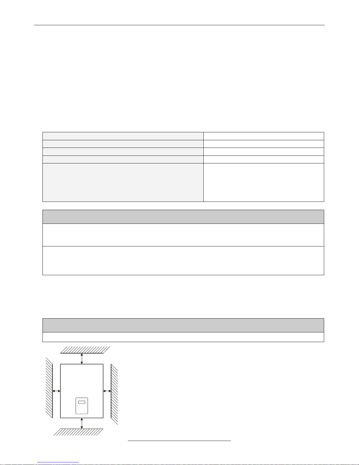
200
50
FREQUENCY
CONVERTER
▪ Beside the side walls at least 50mm, below and above the unit at least 200
mm free space must be provided.
▪ If the device is built in closed control cabinet, overheating of the inside room
must be prevented with proper ventilation!
▪ The slots for fresh air and used air must be held free to assure proper
ventilation. The filters of the slots must be cleaned regularly!
▪ At IP54 versions the cooling is facilitated with heatsinks of increased size
that must be placed outside the cabinet, with maintaining the IP54
protection!
▪ On demand the manufacturer builds the equipment in a cabinet of proper
size.
▪ At types with forced ventilation the inlet openings should be on the bottom
side, the ventilated outlets on the upper side (possible diagonally)
Page 6

H - I - J FREQUENCY CONVERTERS INSTRUCTION MANUAL 0,55 ÷ 200 kW
- 6 -
TEST RUN
In the course of the installation and test run the manufacturer’s attached wiring instructions and the instructions of
the effective standards must be complied with.
8
CAUTION
Test run, maintenance, repair and component replacement in the frequency converter are allowed to be
performed by authorized specialist only!
6
WARNING
ELECTRICAL SHOCK HAZARD
Negligence of these warnings could cause severe injury or even death!
Prior to the total discharge of the capacitors the terminal blocks of the motor must not be touched!
Prior to wiring the connectors of the device switch off the whole power supply of the device! The internal
capacitor remains in charged state even after switching off the power supply. Installation is allowed to be started
if the power LED has ceased lighting.
When taking the equipment from could environment to the place of installation vapour may condense.
Prior to installation wait until the temperature of the equipment equalizes with that of the environment and the
device becomes totally dry.
The appliance must not be put into operation in humid environment.
The circuitries of the frequency converter must not be modified or changed.
In switched-on state the covering of the device must not be removed and any part of it must not be
touched!
The appliance must be earthed according to the standards.
8
CAUTION
DANGER OF UNEXPECTED STARTING
Negligence of this warning could cause injury and property damage!
On switching the line power to the frequency converter, the device depending on its setting may
unexpectedly start the motor.
Prior to powering the frequency converter make sure that nobody stays near to the motor and the machine and
all coverings, mechanical connections, wedges, bolts and machine load are properly fastened!
7
WARNING
FIRE HAZARD
Negligence of this warning could cause fire and injury!
The power line cable must not be connected to the output motor connections of the frequency converter!
Connecting the power line to the output connections could cause severe damage in the device.
Tighten all terminal screws to the specified tightening torque.
Loose electric connections may overheat.
Terminal Size
M3
M4
M5
M6
M8
Tightening Torque [Nm]
0.8 ÷ 1.0
1.2 ÷ 1.5
2.0 ÷ 2.5
4.0 ÷ 5.0
9.1 ÷ 11.0
Page 7

H - I - J FREQUENCY CONVERTERS INSTRUCTION MANUAL 0,55 ÷ 200 kW
- 7 -
8
CAUTION
EQUIPMENT HAZARD
Negligence of this warning could cause total damage to the device.
The device is not waterproof!
Prevent the interior of the appliance from the penetration of water!
Take care that no external object (e.g. small metal part, metal powder) or liquid can get inside the device.
Avoid short circuit or ground fault at the output terminal blocks.
It is forbidden to connect any capacitor to the output. Regarding other filters, please ask the
manufacturer’s opinion.
Avoid using contactor at the output because the frequency converter may stop working due to switch-on
overcurrent.
If for other reasons using a contactor is necessary (e.g. switch-over between motors), the switchover of the
output of the frequency converter during operation must be prevented by latching.
Use the shortest possible earthing conductor and avoid earth loops.
Earthing conductors common with machines of higher power (e.g. welding machine, machine tool) must
not be used.
For wiring the control unit use shielded cable.
Use shielded twisted wires, and connect the shielding to the reference point of the inputs.
Observe proper electrostatic discharge procedures (ESD) when handling the frequency converter.
Failure to comply may result in ESD damage to the drive circuitry.
Do not operate the device with any visible damage on it or if its any part is missing.
Do not modify the circuitry of the frequency converter to avoid damages and expiring of the warranty.
Check all the wiring to ensure that all connections are correct after installing the frequency converter
and connecting other devices.
• Cables and fuses
At connecting the frequency converters use mains fuses and wires with cross-section as given in the table.
TYPE
Minimum
fuse value
(F1, F2, F3)
[A]
Recomm.
cable
[mm2]
TYPE
Minimum
fuse value
(F1, F2, F3)
[A]
Recomm.
cable
[mm2]
TYPE
Minimum
fuse value
(F1, F2, F3)
[A]
Recomm.
cable
[mm2]
V3D 0.55
6.3
0.75 ÷ 1
VLD 5.5
20
2.5 ÷ 4
VHD 30
80
16 ÷ 25
V3D 0.75
6.3
1 ÷ 1.5
VLD 7.5
25
4 ÷ 6
VHD 37
80
16 ÷ 25
V3D 1.1
6.3
1 ÷ 1.5
VLD 11
30
4 ÷ 6
VHD 45
100
25 ÷ 35
V3D 1.5
10
1.5 ÷ 2.5
VLD 15
50
6 ÷ 10
VHD 55
125
25 ÷ 35
V3D 2.2
10
1.5 ÷ 2.5
VLD 22
63
10 ÷ 16
VHD 75
160
35 ÷ 50
V3D 3
16
2.5 ÷ 4
VHD 90
200
50 ÷ 70
V3D 4
16
2.5 ÷ 4
VHD 110
250
70 ÷ 95
VHD 132
315
95 ÷ 120
VHD 160
355
120 ÷ 150
VHD 200
400
150 ÷ 185
VHD 250
500
240 ÷ 300
Page 8

H - I - J FREQUENCY CONVERTERS INSTRUCTION MANUAL 0,55 ÷ 200 kW
- 8 -
• Main and Control Circuit Wiring
• Connecting the power line
At connecting the power line comply with following safety measures:
▪ Use only circuit breakers that have been designed specifically for frequency converters.
▪ If an input switch is used, it is allowed to be used not more than once in every 30 minutes.
▪ Use an AC reactor on the input side of the drive:
• to suppress harmonic current,
• to improve the power factor on the power supply side,
• when using an advancing capacitor switch.
• Connecting the motor
At connecting the motor comply with following safety measures:
▪ The output of the frequency converter has to be loaded with a three-phase motor. In case of any other load
consult with the manufacturer!
▪ Never connect a power source to the drives output.
▪ Never short or ground the output terminals.
▪ Do not use phase correction capacitors.
▪ If using a contactor between the drive and motor, it should never be operated when the drive is outputting a
voltage. Operating while there is voltage output can cause large peak currents, thus tripping the over current
detection or damage the drive.
▪ For connecting the output it is recommended to use shielded cable with earthing at both ends.
▪ With an output cable of longer than 30 meters, an output choke coil has to be used. If the cable length
exceeds 200 meters, the output choke coil is not enough, because of the excessive capacitive load. In this
case, a sine filter has to be used. Regarding the output choke coil or the sine filter, please ask the
manufacturer’s opinion.
• Connecting the protective earth
At connecting the earthing of the frequency converter comply with following safety measures:
▪ Never share the ground wire with other devices such as welding machines, etc.
▪ Always use a ground wire that complies with electrical equipment technical standards. Keep ground wires as
short as possible. Leakage current is caused by the drive. Therefore, if the distance between the ground
electrode and the ground terminal is too long, potential on the ground terminal of the drive will become
unstable.
▪ When using more than one frequency converter, do not to loop the ground wire.
▪ Use earth cable of same cross-section as that of the phase conductors.
• Connecting the control circuitry
At connecting the control circuitry comply with following safety measures:
▪ Separate control circuit wiring from main circuit wiring and other high-power lines.
▪ The connections of the SR connectors of the control circuitry (digital output) have to be separated from other
connectors of the control circuitry, unless they are used for control purposes.
▪ In order to avoid operation errors use twisted pair or shielded twisted pair cables for connecting the control
circuitry.
▪ Be sure to earth the shielding with the largest possible contact area between shielding and earth connection.
▪ The shieldings have to be earthed at the frequency converter side of the cables.
Page 9

H - I - J FREQUENCY CONVERTERS INSTRUCTION MANUAL 0,55 ÷ 200 kW
- 9 -
PUTTING IN OPERATON THE FREQUENCY CONVERTER FOR THE FIRST TIME
8
CAUTION
Prior to put in operation the frequency converter read through thoroughly the description below!
Follow all safety measures, warnings and instructions described in this manual!
Heed the safety messages in this manual.
The operating company is responsible for any injuries or equipment damage resulting from failure to heed the
warnings in this manual.
▪ Check up the operational data of the frequency converter to be put in operation.
page 4. - General features
▪ Install the device according to the instructions.
page 5. - Mechanical installation
▪ Study the safety measures to be complied with.
page 6. - Test run
▪ Connect the cables of the power line, the motor and the control elements to the corresponding terminal
blocks.
page 10. - Assignment and connection of the V3D terminal block
page 13. - Assignment and connection of the VLD / VHD terminal block
▪ If the device is equipped with brake check up the value and the placing of the brake resistor.
page 20. - Selection guide for brake resistors
▪ Switch the line power to the device.
▪ At devices without programming unit the motor can be started with the device’s control elements according
to the default setting (or the required setting).
▪ At devices with programming unit check up and if necessary modify the preset parameters (rising times and
fall times, minimum and maximum frequency etc.)
▪ If possible, perform a trial start with unloaded motor:
• inspect the operation of the motor,
• in case of opposite direction of rotation interchange both phase wires of the motor to achieve the right
basic direction of rotation,
i
Interchanging the phase wires at the mains side does not influence the direction of
rotation!
• with changing the reference signal (e.g. potentiometer) scan the operating frequency band,
• try the functioning of the other controls (e.g. change of direction of rotation)
▪ Let the motor run with load!
▪ If necessary modify the parameters (rising times and fall times, minimum and maximum frequency etc.)
▪ In regulating mode tune the PID parameters
▪ If the settings are appropriate save the parameters!
Programmer’s manual - menu 11-1-2: Save parameters
Page 10
H - I - J FREQUENCY CONVERTERS INSTRUCTION MANUAL 0,55 ÷ 200 kW
- 10 -
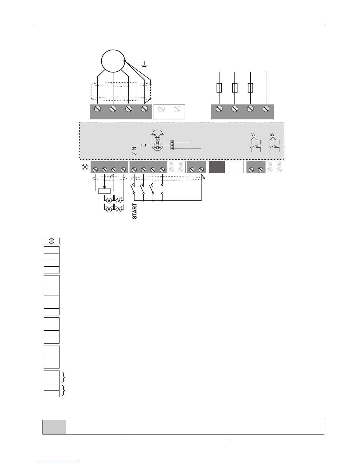
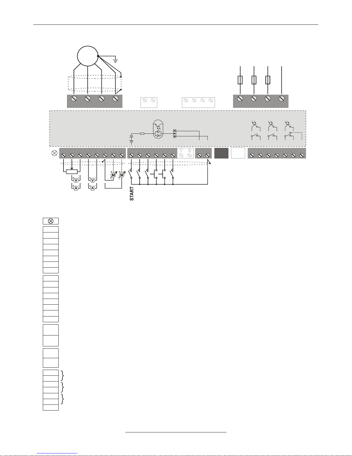
ASSIGNMENT AND CONNECTION OF THE V3D TERMINAL BLOCK
1 1 112 2 223 34 4
SA SD ST CST CSR SR
U V W PE L1 L2 L3 PE
3 x 400VAC
MOTOR
R BRAKE
LINE
2-10K
0÷10V
(0)4÷ 02 mA
REVERSING
JOGGING
ERROR A.
GND/D
M
~
F1 F2 F3
PNP
NPN
12V
12V
1K2
+24V/D
GND/D
Three-colour LED (green: On, yellow: Operate, red: Error)
SA1
+10 V potentiometer driving output (max. 6 mA) (+15 V option)
SA2
Analogue input 1: potentiometer (2÷10 kΩ), 0÷10 V (200 kΩ), 4÷20 mA (0÷20 mA) (200 Ω)
SA3
GND/A (reference point of the analogue inputs)
SA4
Analogue input 2: potentiometer (2÷10 kΩ), 0÷10 V (200 kΩ), 4÷20 mA (0÷20 mA) (200 Ω)
SD1
Digital input 1 * (factory setting: start switch)
SD2
Digital input 2 * (factory setting: reversing switch)
SD3
Digital input 3 * (factory setting: jogging)
SD4
Digital input 4 * (factory setting: error acknowledgement)
SD5
Option (Digital input 5 *, or IRE(A) input)
SD6
Option (Digital input 6 *, or IRE(B) input)
ST1
+24 V/D supply voltage output (max. 100 mA)
In case of PNP logic the common point of the digital inputs (K1, K2 jumpers)
ST2
GND/D (the reference point of the +24 V/D supply voltage output)
In case of NPN logic the common point of the digital inputs (K1, K2 jumpers)
CST
Terminal serial line connector (CAN option, e.g. Master/Slave)
CSR
Option (System serial line and/or CAN)
SR1
Digital output 1 ** (factory setting: ready)
SR2
SR3
Option (Digital output 2 **) (factory setting: operate)
SR4
* Switching level of the digital inputs: 0.6 to 2 mA
** Digital outputs: relay (max. 250 V AC / 1 A or 30 V DC / 0,5 A) or optocoupler (optional) (max. 30 V DC / 10 mA)
i
The analogue inputs 1 and 2 (or analogue inputs 3 and 4) are not equipped with own terminals. If the
configuration includes them, they are connected to the terminals of other functions (mostly to SD5 and 6)
Page 11

H - I - J FREQUENCY CONVERTERS INSTRUCTION MANUAL 0,55 ÷ 200 kW
- 11 -
• Jumper settings
1 12 23 4 1 12 23 4
V3D frequency converter
AK1
AK2
A1
A2
K1
K2
CAN1
RS1
RS2
factory settings
AK1
Setting the analogue output 1 (option)
0÷10 V
(0) 4÷20 mA
AK2
Setting the analogue output 2 (option)
0÷10 V
(0) 4÷20 mA
A1
Setting the analogue input 1
0÷10 V
(0) 4÷20 mA
A2
Setting the analogue input 2
0÷10 V
(0) 4÷20 mA
K1
Setting the digital input 1÷4
NPN logic
PNP logic
mixed
setting is
allowed
K2
Setting the digital input 5÷6 (option)
NPN logic
PNP logic
CAN1
CAN line termination (200 Ω) (option)
Not terminated
Terminated
RS1
Terminal serial line termination (200 Ω) (option)
Not terminated
Terminated
RS2
System serial line termination (200 Ω) (option)
Not terminated
Terminated
• Connections of the incremental rotation speed encoder (IRE) (optional) and thermal protection of
the motor
1 1 12 2 23 3 54 4 6
SA SD ST CST CSR SR
V3D frequency converter
1 2
A
B
+24V
GND
IRE
PTC or
thermal
contact
The signal device can be NPN open collector type, TTL push-pull type or an output with an output voltage of 5 to 24 V.
Independently of the signal transmitter input, the further digital inputs can be operated with both negative and
positive logic circuitry.
The input selected for the connection of the PTC or the thermal contact has to be provided with “External error”,
“opening”.
Page 12
H - I - J FREQUENCY CONVERTERS INSTRUCTION MANUAL 0,55 ÷ 200 kW
- 12 -
• Connecting the brake resistor (optional, in case of built-in brake chopper)
U V W PE L1 L2 L3 PE
V3D frequency converter
M
~
3 x 400VAC
F1 F2 F3
MOTOR
R BRAKE
LINE
The power on the brake resistor (Pnominal / 50 ÷ Pnominal) depends on the braking time and the duty factor.
Selection guide on page 20.
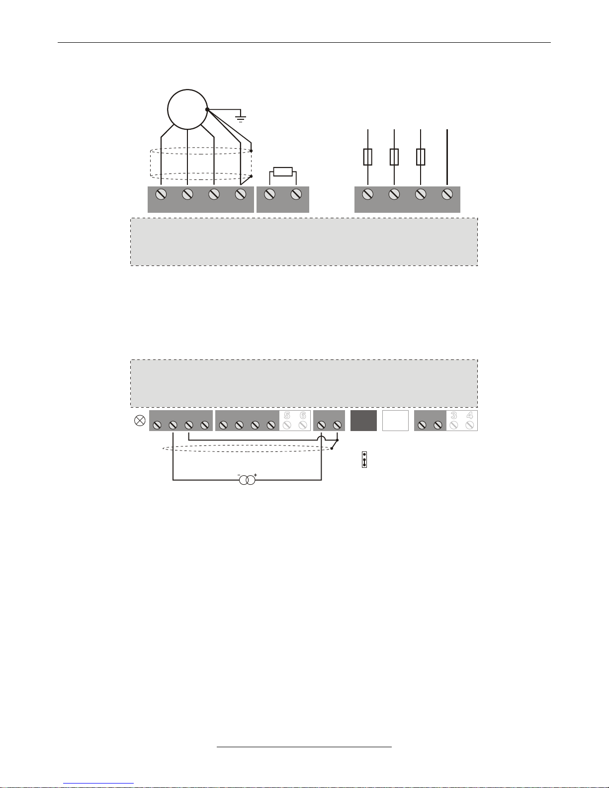
• Connecting a two-wire (4 ÷ 20 mA) remote transmitter
1 1 12 2 23 34 4
SA SD ST CST CSR SR
V3D frequency converter
A1
A1 jumper on the
lower two pins
remote transmitter
1 12 23 4
+24V/D
Page 13
H - I - J FREQUENCY CONVERTERS INSTRUCTION MANUAL 0,55 ÷ 200 kW
- 13 -
ASSIGNMENT AND CONNECTION OF THE VLD / VHD TERMINAL BLOCK
1 1 112 2 223 3 34 4 45 5 56 6 6 77 8
SA SD ST CST CSR SR
U V W PE L1 L2 L3 PE
MOTOR LINE
2-10K
0÷10V
(0)4÷ 02 mA
REVERSING
JOGGING
ERROR A.
GND/D
STOP
M
~
3 x 400VAC
F1 F2 F3
R BRAKE
FAN
3 x 400VAC
PNP
NPN
12V
12V
1K2
+24V/D
GND/D
Three-colour LED (green: On, yellow: Operate, red: Error)
SA1
+10V potentiometer driving output (max. 6 mA) (+15 V, +5 V option)
SA2
Analogue input 1 (+): potentiometer (2÷10 kΩ), 0÷10 V (130 kΩ), 4÷20 mA (0÷20 mA) (100 Ω)
SA3
Analogue input 1 (–): reference point (pl. GND/A)
SA4
Analogue input 2 (+): potentiometer (2÷10 kΩ), 0÷10 V (130 kΩ), 4÷20mA (0÷20 mA) (100 Ω)
SA5
Analogue input 2 (–): reference point (pl. GND/A)
SA6
GND/A (reference point of the analogue inputs and outputs)
SA7
Analogue 1 output: 0÷10V, (0)4÷20mA, (or Analogue input 3: 0÷10 V option)
SA8
Analogue 2 output: 0÷10V, (0)4÷20mA, (or Analogue input 4: 0÷10 V option)
SD1
Digital input 1 * (factory setting: start switch)
SD2
Digital input 2 * (factory setting: reversing switch)
SD3
Digital input 3 * (factory setting: jogging switch)
SD4
Digital input 4 * (factory setting: error acknowledgement)
SD5
Digital input 5 * (factory setting: external error), (or reference signal IRE(A) input option)
SD6
Digital input 6 * (factory setting: stop switch), (or reference signal IRE(B) input option)
SD7
Option (Digital input 7 *, or feedback signal IRE(A) input)
SD8
Option (Digital input 8 *, or feedback signal IRE(B) input)
ST1
+24 V/D supply voltage output (max. 100 mA)
In case of PNP logic the common point of the digital inputs (K1, K2, K3 jumpers)
ST2
GND/D (the reference point of the +24 V/D supply voltage output)
In case of NPN logic the common point of the digital inputs (K1, K2, K3 jumpers)
CST
Terminal serial line connector (CAN1 option)
CSR
Option (System serial line and/or CAN2)
SR1
Digital output 1 ** (factory setting: ready - closing / error - opening)
SR2
SR3
Digital output 2 ** (factory setting: operate - closing / stop - opening)
SR4
SR5
Digital output 3 ** (factory setting: brake control) (optional for VLD 5,5 ÷ 11)
SR6
SR7
Digital output 3: In case of a relay contact closed in rest position (option)
* Switching level of the digital inputs: 0.6 to 2 mA
** Digital outputs: relay (max. 250 V AC / 1 A or 30 V DC / 0,5 A) or optocoupler (optional) (max. 30 V DC / 10 mA)
Page 14

H - I - J FREQUENCY CONVERTERS INSTRUCTION MANUAL 0,55 ÷ 200 kW
- 14 -
• Jumper settings
11 22 3 4 5 6 71 2 3 4 5 6 7 8
VLD / VHD frequency converter
K1
K2
K3
A1P
A1N
A2P
A2N
AK1
AK2
DIF1
DIF2
1 2 3 4 5 6
RS1
RS2
CAN2
CAN1
factory settings
A1P, A1N
Setting the analogue input 1
0÷10V
(0)4÷20mA
DIF1
Setting the analogue input 1
Normal
(- point: GND/A)
Differential
A2P, A2N
Setting the analogue input 2
0÷10V
(0)4÷20mA
DIF2
Setting the analogue input 2
Normal
(- point: GND/A)
Differential
AK1
Setting the analogue output 1
0÷10V
(0)4÷20mA
AK2
Setting the analogue output 2
0÷10V
(0)4÷20mA
KOZOS1
(K1)
Setting the digital input 1-4
NPN logic
PNP logic
mixed
setting is
allowed
KOZOS2
(K2)
Setting the digital input 5-6
NPN logic
PNP logic
KOZOS3
(K3)
Setting the digital input 7-8 (option)
NPN logic
PNP logic
CAN1
CAN1 line termination (200Ω) (option)
Not terminated
Terminated
CAN2
CAN2 line termination (200Ω) (option)
Not terminated
Terminated
RS1
Terminal serial line termination (200Ω) (option)
Not terminated
Terminated
RS2
System serial line termination (200Ω) (option)
Not terminated
Terminated
• High voltage terminal block
U V W PE L1 L2 L3 PE
MOTOR
LINE
VLD / VHD frequency converter
R BRAKE FAN
Ventilator terminal block (3 x 400 V AC, switched together with the cooling ventilators of the frequency converter).
Available for connecting external cooling ventilator (e.g. for cooling the control cabinet), for models VHD 45 to 250
(option)
At models VHD 90 to 250, PE will be connected to a grounding screw.
Page 15

H - I - J FREQUENCY CONVERTERS INSTRUCTION MANUAL 0,55 ÷ 200 kW
- 15 -
• Connections of the incremental rotation speed encoder (IRE) (optional) and thermal protection of
the motor
1 1 12 2 23 34 45 5 76 6 87 8
SA SD ST CST CSR
VLD / VHD frequency converter
1 2 3 4 5 6 7
SR
A
B
+24V
GND
IRE
PTC or
thermal
contact
The signal device can be NPN open collector type, TTL push-pull type or an output with an output voltage of 5 to 24 V.
Independently of the signal transmitter input, the further digital inputs can be operated with both negative and
positive logic circuitry.
The input selected for the connection of the PTC or the thermal contact has to be provided with “External error”,
“opening”.
• Connecting the brake resistor (optional, in case of built-in brake chopper)
U V W PE L1 L2 L3 PE
MOTOR
LINE
VLD / VHD frequency converter
3 x 400VAC
F1 F2 F3
R BRAKE FAN
M
~
The power on the brake resistor (Pnominal / 50 ÷ Pnominal) depends on the braking time and the duty factor.
Selection guide on page 20.
Page 16

H - I - J FREQUENCY CONVERTERS INSTRUCTION MANUAL 0,55 ÷ 200 kW
- 16 -
• Connecting a two-wire (4 ÷ 20 mA) remote transmitter
1 12 23 4 5 6 7 8
SA SD ST CST CSR
VLD / VHD frequency converter
A1P, A1N jumpers
on the lower two pins
remote transmitter
A1P
A1N
1 2 3 4 5 6 7
SR
1 2 3 4 5 6
+24V/D
• ±10 V analogue input (option)
1 12 23 4 5 6 7 8
SA SD ST CST CSR
1 2 3 4 5 6 7
SR
1 2 3 4 5 6
±10V GND
VLD / VHD frequency converter
Page 17

H - I - J FREQUENCY CONVERTERS INSTRUCTION MANUAL 0,55 ÷ 200 kW
- 17 -
OPERATING THE CONVERTER
The source of the reference signal can be:
▪ external or front panel potentiometer,
▪ 0÷10 V,
▪ 4÷20 mA (0 ÷ 20 mA),
▪ front panel controlling terminal,
▪ external or front panel operating terminal (varying with the type),
▪ external or front panel programming terminal (varying with the type),
▪ RS 485 serial line,
▪ CAN bus,
▪ motor potentiometer
The source of the logical control signals can be:
▪ terminal blocks,
▪ front panel controlling terminal,
▪ external or front panel operating terminal (varying with the type),
▪ external or front panel programming terminal (varying with the type),
▪ RS 485 serial line,
▪ CAN bus
• Programming terminal
HIBA ÜZEM
ERROR RUN
ELFOGAD
ENTER
KIJELZŐ
DISPLAY
KILÉP
ESCAPE
KÚSZÁS
JOG
IRÁNY
DIR.
START STOP
▪ It comprises a 4x16 character display and 11 push buttons in
two groups.
Upper group: , , , , DISPLAY, ESCAPE, ENTER,
Bottom group: JOG, DIRECTION, START, STOP.
Operation of the push buttons of the upper (programming)
group:
The push buttons of the upper group permit entering and selecting
data in the Parameter setting mode and in the Display mode.
Operation of the push buttons of the bottom (control) group:
The push buttons of the bottom group permit controlling the
operation of the frequency converter if the terminal has been
preset for the control. The bottom four push buttons work
independently from the upper ones. Therefore if the terminal is
the preset operating control, the motor can be stopped or
started etc. even during entering data.
▪ Default setting in Display mode
(The structure of displaying can optionally be varied: in any line
any parameter can be displayed.)
In line 1: the three parts of the status are displayed:
- Motor status: Run / Stop,
- Dynamic status acknowledgement (e.g. I limit),
- Identification of the frequency converter (e.g. 1).
In line 2: Direction Forw. / Backw.
In line 3: Frequency (e.g. f=50.00Hz),
In line 4: Motor current (e.g. Imotor=6.4A)
▪ It can be used as a built-in unit or in casing as a stand alone unit.
• Operating from the computer
The frequency converter can be connected to the computer through RS485-T line using RS 232 / 485 or USB / RS
485 adapter (interface).
Here the TermOnly program permits setting the frequency converter from the computer and provides a user
interface with the same look as that of the programming terminal.
The ProContact program beyond handling the frequency converter permits reading out, modifying and archiving the
actual parameter set as well as reading out and archiving the event- and error log.
Both programs are available on CD as attachment of the adapter (interface) unit or can be downloaded
from www.procon.hu.
Page 18
H - I - J FREQUENCY CONVERTERS INSTRUCTION MANUAL 0,55 ÷ 200 kW
- 18 -
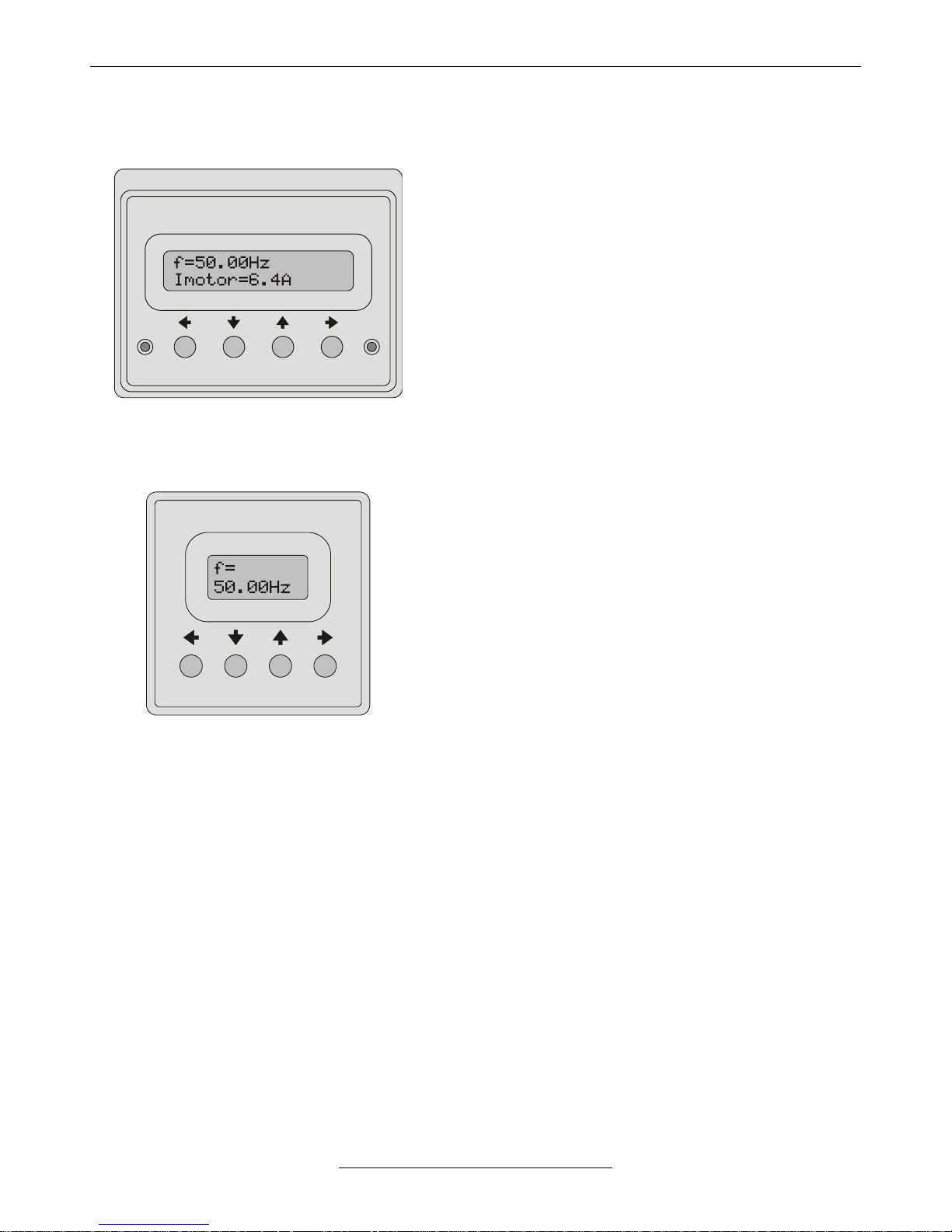
• Operating terminal
ERROR RUN
ESCAPE ENTER
▪ This terminal allows programming the parameters of the
quick menu, displaying 2 parameters and generating
reference signal.
▪ Includes a 2x16 character display, 4 push buttons and displays
for error state and operation state.
▪ Reading in display mode: first row - the frequency, second row -
another parameter (e.g. voltage, current), which can be stepped
with the and arrows.
▪ Reading in programming mode: first row - the name of the
parameter along with its main menu ordinal number (e.g.
2 Control Tup), second row - the submenu ordinal number
and the value of the actual parameter (e.g. 1-1 5.00s), that
can be modified with the push buttons.
▪ In case of error at the end of the first line the ordinal number of
the error, in the second line the name of the error is displayed.
The error list can be stepped with the and arrows.
▪ The terminal can be used as a built-in unit (VHD), in casing as a
stand-alone unit or as an externally mounted unit (e.g. to the
door off the control cabinet).
• Controlling terminal
ENTER
ESCAPE
▪ This terminal allows programming, displaying 1 parameter
and reference signal generation.
▪ Equipped with a 2x8 character display and 4 push buttons.
▪ Reading in display mode: first row - the name of a displayable
parameter (e.g. f=), second row - its value (e.g. 50,00Hz).
The display can be stepped with the and arrows.
▪ Reading in programming mode: first row - the parameter’s
ordinal number in the menu (e.g. 3-1-1), second row - (in case
of a variable parameter) the value of the actual parameter
(e.g. 5.00s), that can be modified with the push buttons.
▪ The terminal can be used built in the front panel of the
frequency converter only!
• Functions of the push buttons (operating and controlling terminal)
(Escape)
▪ Change between display mode and programming mode
▪ Parameter setting mode: shift the cursor to the left
▪ Repeated push: exit parameter setting mode without saving (until the cursor blinks)
▪ At error display: displaying the cause of the error
▪ Display mode: scrolling the displayed variables downward
▪ Programming mode: moving in the menu downward
▪ Parameter setting: decreasing the value or scrolling the selector switches downward
▪ With selected terminal motor potentiometer: decreasing the reference signal
▪ With enabled motor potentiometer start / stop: Stop
▪ Display mode: scrolling the displayed variables upward
▪ Programming mode: moving in the menu upward
▪ Parameter setting: increasing the value or scrolling the selector switches upward
▪ With selected terminal motor potentiometer: increasing the reference signal
▪ With enabled motor potentiometer start / stop: Start
(Enter)
▪ Programming mode: starting the parameter setting
▪ Parameter setting mode: shift the cursor to the right
▪ Repeated push: save parameter value (until the cursor blinks)
▪ Acknowledgement at error
Page 19

H - I - J FREQUENCY CONVERTERS INSTRUCTION MANUAL 0,55 ÷ 200 kW
- 19 -
PROGRAMMING (operating and controlling terminal)
• Programming procedure
(Escape)
▪ Changing from display mode to programming mode
▪ Moving between the menu items
(Enter)
▪ Starting parameter setting
▪ Parameter setting
(Escape)
▪ Repeated push: save parameter value (until the cursor blinks)
or
(Enter)
▪ Repeated push: exit parameter setting mode without saving (until the cursor blinks)
• Quick menu
Submenu
Description, further submenus
Value, range
Default setting
Unit
Parameter - 1 -
2-1-1
control Tup
In default setting the time needed to reach fmax
starting from 0 Hz (in control mode).
0,05 - 3276,7
Depending on
type
s
Parameter - 2 -
3-1-1
control Tdown
In default setting the time needed to reach
f = 0 Hz starting from fmax (in control mode).
0,05 - 3276,7
Depending on
type
s
Parameter - 3 -
6-4
motor In
The durably permitted motor current.
0,5 - dep. on type
Depending on
type
A
Parameter - 4 -
8-1
f maximum
Maximum output frequency.
* default setting is 100 Hz for V3D frequency converters
without operating terminal
0,1 - 1050,0
50,0 *
Hz
Parameter - 5 -
8-2
f minimum
Minimum output frequency.
0,1 - 1000,0
1,0
Hz
Parameter - 6 -
7-2-1
U boost
Starting voltage given to the motor at standing
start.
0,5 - dep. on type
Depending on
type
V
Parameter - 7 -
10-14
active menu
Allows access to the whole menu system for the
controlling terminal.
After switching on/off automatically returns to
handling the quick menu.
quick
all
quick
DRIVING TECHNOLOGY SUPPLEMENTS
• 4x16 character display
▪ Displays the display of the programming terminal.
▪ The display can operate together with the terminal, since it only
receives data and does not answer through the serial line.
▪ The display can be used in built-in form (VHD) or as an
externally mounted unit (e.g. to the door of the control cabinet).
Page 20

H - I - J FREQUENCY CONVERTERS INSTRUCTION MANUAL 0,55 ÷ 200 kW
- 20 -
• Potentiometer (2 ÷ 10 kΩ, linear)
Wiring:
1 2 3
Frequency conv.
terminal blocks
Potentio-
meter
SA 1
1
SA 2
2
SA 3
3
• Selection of the brake resistors at dynamic braking
The power on the brake resistor depends on the braking time and the duty factor. (Pnominal / 50 ÷ Pnominal)
The necessary power is determined by the braking time and the duty factor.
( see: Programing manual, support for dimensioning the brake resistor)
Frequency
converter type
Resulting
resistance
V3D 0.55 - 1.1
≥ 200 Ω
V3D 1.5 - 4
≥ 100 Ω
VLD 5.5
≥ 50 Ω
VLD 7.5 - 11
≥ 25 Ω
VLD 15
≥ 20 Ω
VLD 22
≥ 13 Ω
VHD 30 - 37
≥ 11 Ω
VHD 45 - 55
≥ 8 Ω
VHD 75 - 90
≥ 4,5 Ω
VHD 110 - 160
≥ 3,3 Ω
VHD 200
≥ 2,2 Ω
▪ 100 W wire-wound
resistors
(50÷200 Ω)
▪ 500 W wire-wound
resistors
(50÷100 Ω)
▪ 2÷4 kW cased brake
resistor modules
(12,5÷100 Ω)
VHD 250
≥ 1,6 Ω
8
CAUTION
The brake resistors are imposed to high voltages of 660 V DC.
The appliance must be installed and wired very carefully because of heat developing and for proper
electric shock protection.
For wiring use cables with heat-resisting coating.
MAINTENANCE
At normal operation the device needs no maintenance. Depending on the surroundings inspect regularly the
ventilators, and at models built in cabinet also the condition of the filter cartridge.
Inspect the screwed fastenings according to the local maintenance regulations, but at least once a year.
GUARANTEE AND REPAIR
The products come with a guarantee period of 24 months.
8
CAUTION
The guarantee covers normal operation only.
In case of improper storage, improper use or unauthorized intervention the guarantee terminates.
Repair will be accomplished both within the guarantee period and after in the manufacturer’s premises, the
appliance has to be transported there by the user.
Page 21

H - I - J FREQUENCY CONVERTERS INSTRUCTION MANUAL 0,55 ÷ 200 kW
- 21 -
FREQUENCY CONVERTER SELECTION GUIDE
0.55
0.75
1.1
1.5
2.2
3
4
5.5
7.5
11
15
22
30
37
45
55
75
90
110
132
160
200
250
(kW)
F
H
I
J
TYPE
Output
power
[kW]
Nominal
current
[A]
Peak
current
[A]
Mass
[kg]
Physical dimensions [mm]
Fastening
screws
Width
Length
Height
Fastening
Three phase, 3 x 380 ÷ 440 V AC input
V3D 0.55
0.55
1.7 3 2
128
210
91
90 x 200
4 x M4
V3D 0.75
0.75
2.6
4
2.5
128
210
142
90 x 200
4 x M4
V3D 1.1
1.1
3.2
5
2.5
128
210
142
90 x 200
4 x M4
V3D 1.5
1.5
4.2 6 3
128
240
150
90 x 230
4 x M4
V3D 2.2
2.2
6 9 3
128
240
150
90 x 230
4 x M4
V3D 3
3
8
12 4 128
280
150
90 x 265
4 x M4
V3D 4
4
10
14 4 128
280
150
90 x 265
4 x M4
VLD 5.5
5.5
14
19 8 190
290
220
170 x 280
4 x M5
VLD 7.5
7.5
18
30
12
190
390
220
170 x 380
4 x M5
VLD 11
11
26
37
12
190
390
220
170 x 380
4 x M5
VLD 15
15
35
57
14
190
490
220
170 x 470
4 x M5
VLD 22
22
48
75
20
290
490
220
260 x 470
4 x M6
VHD 30
30
62
95
38
300
590
300
260 x 550
4 x M8
VHD 37
37
75
115
38
300
590
300
260 x 550
4 x M8
VHD 45
45
90
135
65
400
740
300
360 x 700
4 x M8
VHD 55
55
110
150
65
400
740
300
360 x 700
4 x M8
VHD 75
75
150
220
80
500
740
300
460 x 700
4 x M8
VHD 90
90
180
255
85
500
790
300
460 x 750
4 x M8
VHD 110
110
220
310
110
500
1100
335
460 x 900
4 x M10
VHD 132
132
260
360
115
500
1100
335
460 x 900
4 x M10
VHD 160
160
320
450
120
500
1100
365
460 x 900
4 x M10
VHD 200
200
400
540
120
500
1100
410
460 x 1040
4 x M10
VHD 250
200
500
670
125
500
1100
410
460 x 1040
4 x M10
Page 22

H - I - J FREQUENCY CONVERTERS INSTRUCTION MANUAL 0,55 ÷ 200 kW
- 22 -
PERIPHERAL EQUIPMENT SELECTION GUIDE
ITEM
E3D
V3D
VLD
VHD
3 x 400 V line voltage
Built-in mains noise suppressor
IP20 cabinet
IP54 cabinet
Analogue input 1 - 2
Analogue input 3 - 4
–
±10V analogue input
–
–
Analogue output 1 - 2
–
Digital input 1 - 4
Digital input 5 - 6
–
Digital input 7 - 8
–
–
Digital output 1
Digital output 2
Digital output 3
–
–
RS-485 serial line 1 (Terminal)
–
RS-485 serial line 2 (System)
–
USB / RS 485 interface
–
RS 485 / 485 interface (optical light cable type)
–
USB / RS 485 interface (optical light cable type)
–
CAN bus 1
–
CAN bus 2
–
–
Reception of incr. rotation speed encoder 1
–
Reception of incr. rotation speed encoder 2
–
–
Built-in dynamic brake
Brake resistor
Mains (input) choke
Output (motor) choke
Stand-alone programming terminal (4 x 16)
–
Built-in programming terminal
– – –
Stand-alone operating terminal (2 x 16)
–
Built-in operating terminal
– – –
External operating terminal
–
Built-in controlling terminal (2 x 8)
Built-in display (4 x 16)
– – –
External display
–
Built-in potentiometer
External potentiometer
Markings
Basic configuration
Option
– Not applicable
Page 23

Page 24

PROCON Hajtástechnika Kft.
H-1047 Budapest, Kisfaludy u. 4.
Tel./fax: +36 1 370 9699
+36 1 379 5387
e-mail: procon@procon.hu
info@procon.hu
Internet: www.procon.hu
Edition: April, 2018
I
II
III
IV
V
VIII
IX
X
XI
XII
XIII
XIV
XV
XVI
XVII
XVIII
XIX
XX
XXI
XXIII
XXII
B
a
r
o
s
s
u
.
V
á
c
i
ú
t
T
í
m
á
r
u
.
N
y
i
t
r
a
u
.
T
i
n
ó
d
i
u
.
P
e
r
é
n
y
i
Z
s
i
g
m
o
n
d
u
.
K
i
s
f
a
l
u
d
y
u
.
S
ö
r
é
t
g
y
á
r
u
.
S
e
m
m
e
l
w
e
i
s
u
.
L
a
b
d
a
r
ú
g
ó
u
.
L
a
b
d
a
v
e
r
ő
u
.
M
i
l
d
e
n
b
e
r
g
e
r
u
.
B
á
n
y
a
g
é
p
g
y
á
r
u
.
D
u
n
a
s
o
r
M
e
g
y
e
r
i
ú
t
 Loading...