

Procon 8450-02, 8455-02, 8465-02, 8460-02, 8701 Installation Manual
www.procon.co.uk
IP Control Units
8450-02 (3 port version)
8455-02 (1 port version)
8460-02 (3 port version with real-time clock)
8465-02 (1 port version with real-time clock)
8701 control system with IP interface
Tel: +44 (0)1442 242 224
E-Mail: technical@procon.co.uk
Installation Guide

www.procon.co.uk
-
1 -
IP Control Unit
Installation Guide
Revision 1.0 Dated 20 June 2005
Contents
1. Introduction to the ProCon IP Control Unit .................................................................................................... 2
1.1 General Description.................................................................................................................................. 2
1.2 Electrical Specifications............................................................................................................................ 2
2. Getting Started ...............................................................................................................................................3
2.1 Physical Connections...............................................................................................................................3
2.2 Using the loop through facility .................................................................................................................. 4
2.3 Example installation ................................................................................................................................. 4
3 Connecting your IP Control Unit to a network................................................................................................. 5
3.1 Connecting the Control Unit via a crossover cable .................................................................................. 5
3.2 Connecting the Control Unit to a network with a DHCP server................................................................ 7
3.3 Connecting the Control Unit using a static IP address (single subnet network) ...................................... 8
3.4 Connecting to a network with multiple subnets ........................................................................................ 9
Appendix A – Troubleshooting......................................................................................................................... 10
A.1 I have connected my Control Unit but can’t see it in Site Manager® .................................................... 10
A.2 The interface has not picked up the correct IP address via DHCP ....................................................... 10
A.3 The ‘link’ light does not light when the network cable is inserted ..........................................................10
A.4 Why is the ‘link’ light red sometimes? .................................................................................................... 10
Appendix B – Revision History......................................................................................................................... 11
Tel: +44 (0)1442 242 224
E-Mail: technical@procon.co.uk

www.procon.co.uk
-
2 -
IP Control Unit
Installation Guide
Revision 1.0 Dated 20 June 2005
1. Introduction to the IP Control Unit
1.1 General Description
The ProCon IP Control Unit allows you to connect your RS232 controlled products to an IP infrastructure and
control them from a single point using the ProCon Site Manager® software.
There are five variants of the ProCon IP Control Unit available, all of which have the following features. See
table 1.1 for a comparison chart of the differences between the variants.
• DHCP or manually configured IP address, subnet mask & default gateway.
• Built in e-mail server so alerts are sent even when Site Manager® software is not running.
• 2 available e-mail addresses for multiple alerting.
• Closed loop that can trigger an e-mail alert when the loop is broken, allows hardware to act as a
security measure for expensive audio visual equipment.
• 2 built in timers that can trigger alerts for measuring usage, i.e. e-mail gets sent when the filter on a
projector needs changing.
• Projector lamp expiration alert (uses one of the timers), sends an e-mail to notify that a projector
lamp has passed a preset duration and needs changing (requires Site Manager® software to be
running)
• Infra red port for controlling non-RS232 devices such as VCR’s and DVD players.
• Built in scheduling that operates from the onboard clock allowing events to occur without Site
Manager® software.
8450-02 8455-02 8460-02 8465-02 8701-03
Number of RS232 ports 3 1 3 1 2
Loop through port √ x √ x x
Power extension port √ x √ x x
Battery backed rtc x x √ √ √
RS232 Interface 13 pin phoenix D9 male 13 pin phoenix D9 male 3 pin phoenix
Closed loop interface 13 pin phoenix 2 pin phoenix 13 pin phoenix 2 pin phoenix 2 pin phoenix
IR Interface 13 pin phoenix 3.5mm jack 13 pin phoenix 3.5mm jack x
Table 1.1 Comparison of the IP Control Unit variants
1.2 Electrical Specifications
8450-02 8455-02 8460-02 8465-02 8701-03
Supply voltage 12V 12V 12V 12V mains
Supply current (@12V) 250mA 300mA 250mA 300mA X
Power supply included 12V 500mA 12V 500mA 12V 500mA 12V 500mA X
Current drawn with
8416-03 ProCon
Control Panel attached
to power loop through.
Operating temperature 0° - 70° F 0° - 70° F 0° - 70° F 0° - 70° F 0° - 70° F
Table 1.2 Electrical specifications of the IP Control Unit variants
375mA
375mA
425mA
425mA
X
Tel: +44 (0)1442 242 224
E-Mail: technical@procon.co.uk

www.procon.co.uk
-
3 -
IP Control Unit
Installation Guide
Revision 1.0 Dated 20 June 2005
2. Getting Started
2.1 Physical Connections
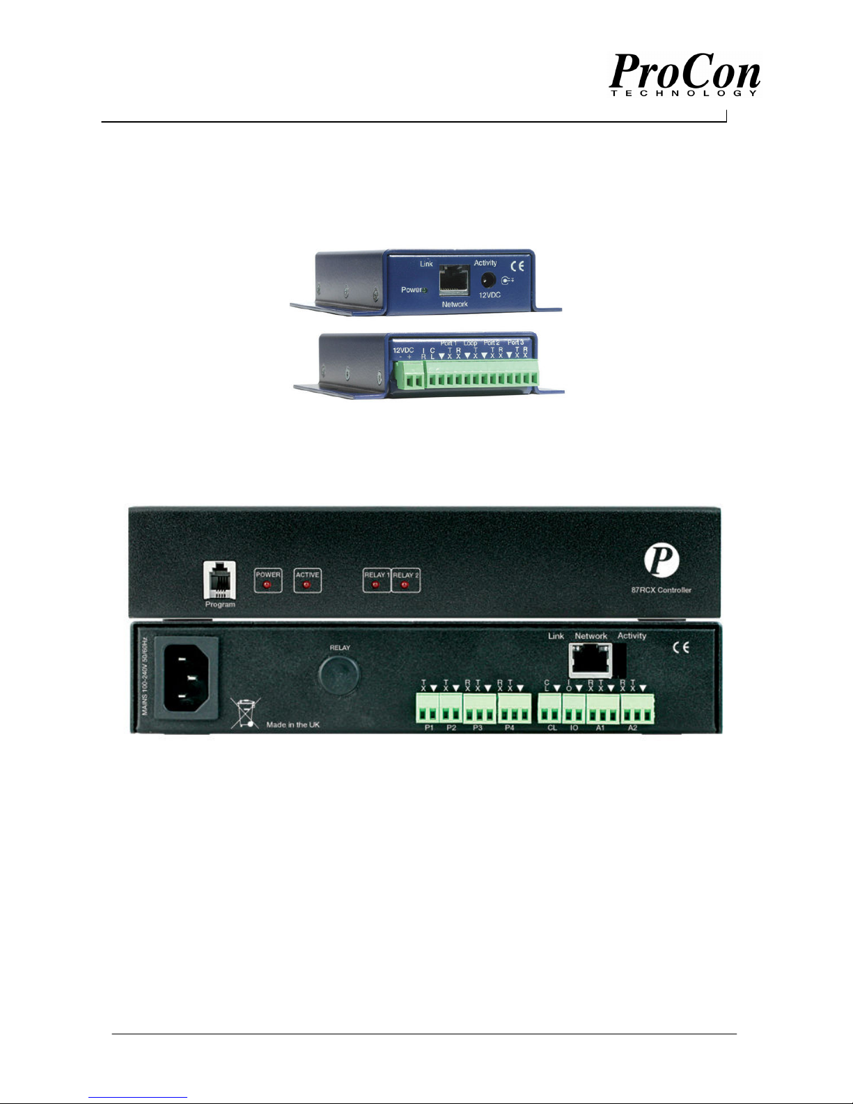
Figure 2.1 shows a picture of the IP Control Unit connections to the power supply and network.
Figure 2.1 Power / network end of the IP Control Unit
Item Description
12VDC Socket for the 2.1mm connector on the power supply
Network Cat 5 socket accepts standard network cable
Power LED Indication that the unit has got power supplied
Link LED Indicator to show that the interface is connected to a network
Activity LED Indicator blinks when data is being sent / received over the network
Table 2.1 Description of the casing labels for the power / network end
Figure 2.2 shows the RS232 side of the Control Unit and connections to the power loop through, Infra red
(IR) and closed loop, details of the connections are described in tables 2.2 / 2.3.
Figure 2.2 Interconnect side of the IP Control Unit (8450-02 / 8460-02)
Item Description
Power 12VDC Can be used as either a loop through power supply if the 12VDC socket is used
on the front of the interface or alternatively can be used to supply the interface
with 12V @ 500mA if an alternative power source to the one supplied is required.
IR Connection to the infra red emitter, this is the positive side of the emitter the other
side is wired into one of the ground (▼) points.
CL A connection between this point and ground (▼) signifies a closed loop, once this
connection is broken from ground then an alarm will trigger if required. If this
feature is not used then this connection can be left unused.
Port 1 Bi-directional connection to the first RS232 controlled device. Connect the ‘TX’ to
the ‘RX’ of the device to control and the ‘RX’ to the ‘TX’ of the device to control
with the ground connections commoned together.
Loop This port is input only and any RS232 signals received will be transmitted back out
of Port 2. See section on interface operations.
Port 2 See Port 1 for connection to the second RS232 device.
Port 3 See Port 1 for connection to the third RS232 device.
Table 2.2 Description of the connections on the 8450-02 / 8460-02
Tel: +44 (0)1442 242 224
E-Mail: technical@procon.co.uk
 Loading...