

www.procon.co.uk
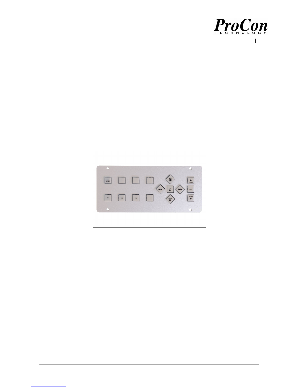
Programmable Control Panel
03 Models
8404 / 8406 / 8408 / 8416
Instruction Manual
Tel: +44 (0)1442 242 224
E-Mail: techical@procon.co.uk
Tel: +44 (0)1442 242 224
www.procon.co.uk
Button15
Button12
Description
The panels are designed to be easily programmable allowing control of equipment by RS232 commands and
InfraRed. The system can be expanded to control equipment by contact closure using our Relay unit. More
buttons can be added using our Slave Panels. The 8400s have two IR or RS232 ports, two dedicated
RS232 ports and one I/O port. Each button has LED feedback. Four, Six, Eight and Sixteen button panels
are available. The panels are programmed using ProCon software. This is found on our CD catalogue or
Website www.procon.co.uk
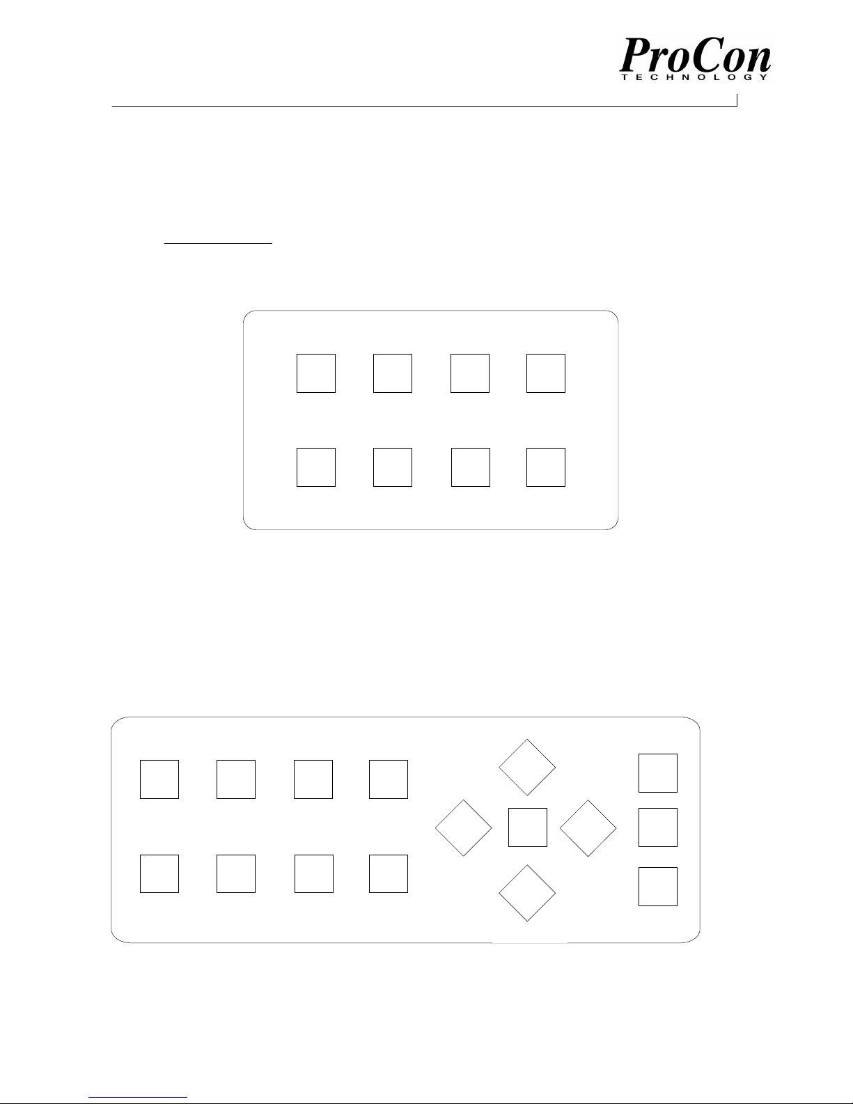
Button Labelling for 8 Button Master and (Slave Panels)
Button1/9/17 Button2/10/18 Button4/12/20 Button3/11/19
Button5/13/21 Button8/16/24 Button7/15/23 Button6/14/22
Master Panel buttons are always numbered 1 to 8. Slave panels can be configured for (1 to 8), (9 to 16) or
(17 to 24).
The buttons are numbered as above for programming purposes. When using the Four button version buttons
2/3/6/7, (10/11/14/15), (18/19/22/23) only are used and when using the Six-button panel only 1/2/4/5/6/8,
(9/10/12/13/14/16), (17,18,20,21,22,24) are used.
Button Labelling for 16 Button Master and Slave Panel
Button1 Button2 Button4 Button3
Button5 Button8 Button7 Button6
16 Button panels are always numbered as above.
A range of pre-labelled buttons are available or button can be custom labelled by printing on A4 acetate.
Button13
Button14
Button9
Button11
2
E-Mail: technical@procon.co.uk

Tel: +44 (0)1442 242 224
www.procon.co.uk
PIR Switch
RX
(9600 Baud)
A template is available as a Word document on the CD catalogue under ‘Label8x.doc’. The document shows
boxes with popular button names and each can be edited as required. When printed cut out the labels along
the black outline.
To fit the labels pop the buttons out from underneath the panel noting the orientation. Remove the lens cap
and the lens and insert the label into the lens cap. Refit the lens and then carefully push the button back into
place.
Buttons can be factory Pre-labelled. Contact ProCon Sales for details.
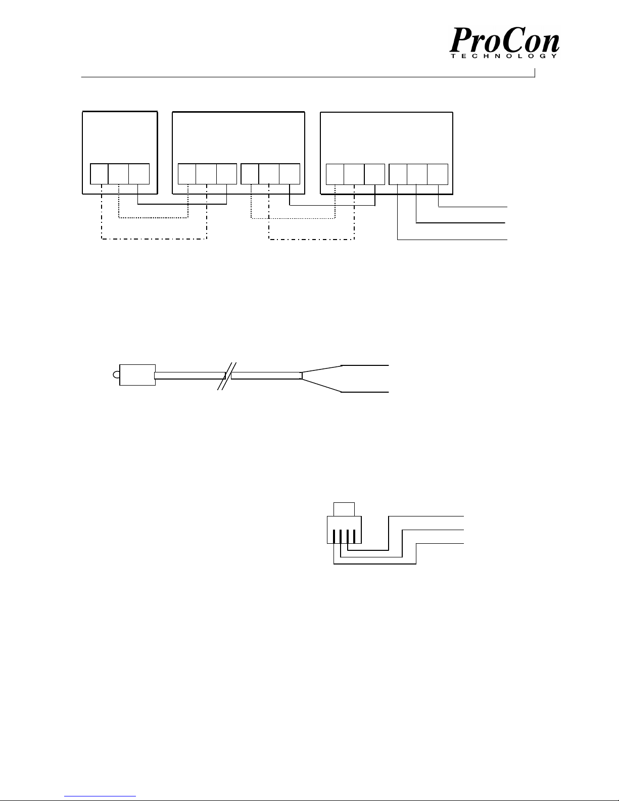
Installation
The panel is powered from the supplied 12V power pack, although any 12V non-regulated supply may be
used. Connect the white strip lead to the 12V+ve screw terminal on the panel PCB and the Black lead to the
–ve. When the panel is powered up or a program downloaded, button 2 (and 10 on 16 button panel) will
flash for 2 seconds then extinguish. This indicates the panel self test has passed.
All four ports may be used for general RS232 control but when using the Procon expansion units the Xport
must be used exclusively. In this case the Xport RX must be connected to the Expansion unit TX.
DO NOT USE THE XPORT RX CONNECTION WITH ANY OTHER DEVICE.
Connect the TX and Gnd of the panel ports to the RS232 RX and Gnd of the Equipment to be controlled.
Ports 1 and 2 can be used for IR or RS232 control. Ports 3 and Xport are used for RS232 control but when
using the Procon expansion units the Xport must be used exclusively. In this case the Xport RX must be
connected to the Expansion unit TX.
Typical 8400 installation
RX TX Gnd
TX Gnd
ProCon 8300
Max. cable length 25m/80ft.
PROJECTOR
Max. cable length 25m/80ft.
I/O Port
This can be configured to give a High or Low TTL level (eg. For switching a relay interface) or for detecting a
High to Low or Low to High state. (eg. For detecting an external switch such as a PIR)
Output State Input State
I/O Gnd
Relay
Interface
3
TX Gnd TX Gnd
VCR
DVD
I/O Gnd
E-Mail: technical@procon.co.uk
Tel: +44 (0)1442 242 224
www.procon.co.uk
Slave Panels
Master
RX TX Gnd
To Master
RX TX Gnd
Slave
TX RX Gnd
From Slave
Slave
To Master
RX TX Gnd
From Slave
TX RX Gnd
Slave Panels can be daisy-chained as above. If other ProCon units are used then they should be connected
between the Master & Slave Panels. Use screened cable to link to units. The maximum cable length
between panels should not exceed 25m/80ft.
IR Transmitter
The IR transmitter heads are connected as follows:
Black or Braid to Port GND
Transmitter must be place directly in
front of the Device IR window.
Blk\White or Signal wire to Port TX
Program Download
To Download a program to the Panel connect the Programming cable to the Panel Program socket and the
Serial Port of the PC.
Programming Cable Pin Connections
RJ10 Plug
Front View
Pin 5 (Gnd)
Pin 3 (Tx)
Female D9 Connector
PC Serial Port
4
E-Mail: technical@procon.co.uk

Tel: +44 (0)1442 242 224
www.procon.co.uk
Getting Started
The panels are programmed using the ProCon84X software.
For panels with 01\02 suffix we recommend using version 3.92.
For panel with 03 suffix we recommend using version 4.4 or later.
The software can be used directly from the CD or loaded onto a PC by running Set Up from the Software
folder.
The software allows the panel to perform various functions such as RS232/IR control / Button Feedback /
Delay Time / Relay Control / Time Out if a button press is not detected after a certain time period. Run the
ProCon84X software and click on ‘Help’ click on ‘Getting Started’. This gives a brief description of the how to
use the software. Close the window then click on ‘Help’ then ‘HelpWindow On’. This gives a description of
the major items as the Cursor passes over them. Take time to familiarise yourself with the items.
Programming Step by Step
Each button is programmed individually it can be made to action on Pressing or Releasing. It can be
programmed to Toggle for up to 4 Presses or it could be assigned to a Bank of buttons having the same
function but controlling different equipment. A Script is written for each button containing up to 24 events. A
script can be written for events to action when the Panel is powered up by selecting ‘Start Up’ from the
Program Button dropdown list.
An Event could be an RS232 command, a button Feedback, a Delay Time etc..
When all the buttons have been programmed the information can be Downloaded to the panel.
Start by running the Procon84X software.
Feedback
A button LED has 3 states. On / Off / Flash. It can be assigned to a group where only one LED of the group
may be on at any one time.
To add Feedback to a Button Script (Example)
Select a button to program from the ‘Program Button’ dropdown list.
Click on ‘Add Panel Feedback’. This will open up the Feedback window.
The chosen button LED will be listed as the default although any button LED may be selected.
Select ‘On’ from the Action dropdown list and click on ‘Add to Script’. The Event Script will show Event1 as
being the chosen button Feedback On. Chose another Feedback LED and click on ‘Flash’ add this to the
Script. The Event Script will now show Event2 as being the chosen LED Flash.
Now Test the program by going to the ‘Download’ section.
When the panel has been loaded Press the programmed button. The chosen button for Event1 will illuminate
and the button for Event2 will flash. Try programming other buttons with On / Off / Flash actions.
To Save any programs click on Save from the File menu and give them a title.
5
E-Mail: technical@procon.co.uk

Tel: +44 (0)1442 242 224
www.procon.co.uk
On / All Buttons Off
This function will illuminate the chosen Feedback button and turn off any other on the panel.
On / Group Off
This allows you to assign an LED to a group where only one of the group may be illuminated at a time. For
instance Play / Stop / Pause. An LED may be assigned to up to 8 groups.
To illustrate this, clear the program by selecting ‘New’ from the File menu.
Select Button 1 to program and open the Feedback window. From the Action list select ‘On/ Group Off’. Click
on ‘Group1
’. Repeat for Buttons 2 to 4.
Select Button 5 to program, open the Feedback window and select On/ Group Off, click on ‘Group2
’. Repeat
for buttons 6 to 8.
Download the program to the Panel.
Press Button1, this will illuminate. Now press Button2, this will illuminate and extinguish Button1. Only the
pressed button of 1 to 4 will stay illuminated.
Likewise only the pressed button of 5 to 8 will stay illuminated.
Delay Time
A delay time can be added in between events in a Script. This can be from 0.5 seconds up to 24hours. The
delay is absolute and no other Event or Button press will be acknowledged until the time period has elapsed.
Adding Delay Time to a Script. (Example)
Select a Button to program and Add Feedback Button to Flash as Event1.
Click on ‘Add Time Delay’. This opens up the Delay time window. Using the scroll bars you may set a time
period. For this example set the Time period for 5 seconds. Click on ‘Add to Script’. The Set delay now
appears as Event2.
Select the Feedback button action to On and add to script as Event3.
Download the program and press the programmed Button. This will flash for 5 seconds then stay On.
RS232 Command
The Panel can be programmed to output an RS232 command on a Button action.
A command is contained within a Library.
Select ‘New’ from the File menu to clear the program.
Click on ‘Add RS232 Function’ this will display the RS232 window. The window will tell you
the current library selected. The default is the Proconlib library containing the RS232 commands for ProCon
equipment set at address 0. If the Device to control is within another Library then click on ‘Change Library’
and select the library to display.
To add an RS232 command to an event, first select the device to control from the dropdown menu then the
function. Next select the panel port the device is connected to. Finally select the action. This may be Send
Once, Send No. of Times or Send Continuous. Send Once will send the command string one time only. Send
6
E-Mail: technical@procon.co.uk

Tel: +44 (0)1442 242 224
www.procon.co.uk
No. of times allows you to send a command up to 50 times, selectable from a scroll bar. Also you may set a
delay time between strings, again selectable from a scroll bar. Send Continuous will send continuous strings
while a button is actioned. A delay time can be set between strings. This action is useful for Volume Up and
Down commands with ProCon equipment. Setting a delay time of 150mS between strings gives a steady
ramp up and down.
When the RS232 parameters have been set click on ‘Add to Script’.
RS232 Libraries
To Add or Edit information to libraries first open the RS232 window then click on ‘View RS232 Library’.
This will display a new page showing the currently selected Library Contents. To view a functions’ Protocol
and string settings, Select the Device from the Dropdown menu and its’ function. All the relevant information
will be displayed. Protocol can be changed by selecting new settings for Baud rate, Data bits and Stop bits.
Command strings can be edited by changing Byte values. All Byte values are entered in Hex, Ascii or
Decimal. Select the type from ‘Code Format ‘ in the menu bar. When an edit is complete click on ‘Save Edit’
to store new values. To add a new device to a Library click on ‘Add New Device’. Enter the Information then
‘Save’. The screen will then prompt you a to name a Function. Type the Function name in the box then enter
the command string and Protocol. Click ‘Save Edit’ to store.
A new function can be added to an existing Device by clicking on ‘Add New Function’.
To copy a list of functions from an existing device to a new device first select the device to copy from
then click on ‘Copy Functions’. Type in new device and description then save.
For easy finding of Functions it is recommended that groups of Libraries are made containing common
Devices. New Libraries can be created by clicking on New from the File Menu. Save the Library using a
relevant name, such as the equipment Brand name or Projector etc.. Devices and Functions can be added to
the Library as above.
As a confidence check when editing or adding, a function can be tested by directly connecting the PC to the
Device RS232 port. Select the PC serial port you are using from the dropdown list and press ‘Test’. The
Device should then respond to the command sent.
To connect to a Device a test cable can be made as follows:
PC Serial Port (female D9 connector)
Pin 3 to Device (RX) / Pin 5 to Device (Gnd)
Verifying RS232 Commands
To check a command from a Panel Port use the Verify Command screen.
First go to the RS232 Library screen and click on Verify Command from the Menu Bar, this will bring up the
Verify Command screen.
A cable will be required to connect the Panel port to the PC serial port. Connections are as follows:
Port TX to female D9 Pin 2
Port Gnd D9 Pin 5
From the dropdown list select the PC serial port the cable is connected to.
Set the Baud rate, Data Bits and Stop bits to match the command Protocol.
Click on ‘Capture Command’ then press the Panel button to transmit command.
The captured string will appear in the Byte boxes. This should match the string in the Library.
7
E-Mail: technical@procon.co.uk

Tel: +44 (0)1442 242 224
www.procon.co.uk
Infra Red Command
The Panel can be programmed to output an Infra Red function on a Button action.
A function is contained within a Library.
Select ‘New’ from the File menu to clear the program.
Click on ‘Add IR Function’ this will display the IR window. The window will tell you the current library
selected. If the Device to control is within another Library then click on ‘Change Library’ and select the
library to display. To add an IR function to an event first select the device to control from the drop down list
then the function. Next select Panel or the address of an 8300 unit from the address list then the panel port
the device transmitter head is connected to. Finally select the action. This may be Send IR Pulse, IR Pulse
number or Send Continuous. Send IR Pulse will send the IR function one time only. IR Pulse No. allows you
to send a function up to 120 times, selectable from a scroll bar. Send Continuous will send continuous
pulses while a button is actioned. This action is useful for Volume Up and Down and Cursor functions. When
hardwiring to a device the carrier may have to be turned off, refer to Manufacturers instructions, otherwise
carrier must be left On.
When the IR parameters have been set click on ‘Add to Script’.
Infra Red Libraries
To Add information to libraries first open the IR window then click on ‘View IR Library’.
This will display a new page showing the currently selected Library Contents. To view a functions’ data,
Select the Device from the Dropdown menu and its’ function. All the relevant information will be displayed.
To add new devices and functions a Procon 8300 or 8350 IR Learner unit will be required.
Connect the 8300/8350 Program Port to a PC serial Port using the standard programming cable.
From the menu bar select the PC Serial Port the cable is connected to.
To add a new device to a Library click on ‘Add New Device’. Enter the Information then ‘Save’.
Click on ‘Learn New Function’. Enter a name for the function then follow the on screen instructions.
Capture status ‘A’ led will turn Red indicating Ready to Learn. When function has been learnt the led
will turn Green. Status ‘B’ will turn Red indicating a presence of InfraRed. This is a useful indication
that a handset is working. When a function has been learnt the screen will prompt to Test. If using an 8300
select the IR Port from the drop down list the Transmitter head is connected to and place head in front of the
Device IR window. If using an 8350 place the unit in front of the device. Click on ‘Test’.
The screen then prompts ‘Confirm’. If function operates click on ‘Yes’ otherwise click on ‘No’ and follow the
on screen instructions. A library function can be re-learnt by clicking on ‘Re-Learn Function’ and following the
above procedure.
For easy finding of Functions it is recommended that groups of Libraries are made containing common
Devices. New Libraries can be created by clicking on New from the File Menu. Save the Library using a
relevant name, such as the equipment Brand name or Projector etc.. Devices and Functions can be added to
the Library as above.
A function can be tested at any time by using an 8300 or 8350 and connecting to a PC.
Select a function and relevant IR Port and click on ‘Test’.
I/0 Ports
A panel has one I/O port the 8300 has two.
An I/O port can be configured for ‘Input or Output’.
8
E-Mail: technical@procon.co.uk

Tel: +44 (0)1442 242 224
www.procon.co.uk
Output means the port can be controlled to give a High state (+5v TTL) or a Low state (0v). This useful for
switching relays etc.
Input means that a script can be actioned when a High to Low or Low to High state is detected on the Port.
This is useful for external detection of a switch or PIR.
9
E-Mail: technical@procon.co.uk

Tel: +44 (0)1442 242 224
www.procon.co.uk
The default setting of all IR ports is Output. To change to Input click on ‘I/O setup’ from the Menu bar.
The I/O Ports gives a list of all possible I/O ports on a system. To change a Panel port to Input select ‘Panel
I/O Port’ from the top of the list. To change an 8300 I/O port select the address of the unit from the list and
the Port number. A maximum of 4 ports can be configured for Input. Once the Port settings have been
confirmed they cannot be reset within a program. If a mistake has been made select New from the file menu
and start again.
To add an Output function to a script click on ‘Add Output function’ this will display the Output window.
The Unit address displays all the possible Output ports on a system. From the list select the Port and the
state to change to and add to a button script. When the button is actioned the Port will change to the
programmed state.
To write a script for an Input port click on ‘Button’ from the Menu bar and select Input Port.
A list of the configured Input ports will appear. Select the Port and the state change from the list and write a
script as normal. When the programmed Port state is detected the script will action. If the Panel is ‘busy’
when the state change occurs the script will action when the Panel is ‘free’. To return to the button list select
Press from the Button menu.
Button Action
A button action can be changed by clicking on ‘Button’ from the menu bar. 4 options are available.
Press – script is programmed for a button press. Release – script is programmed when a button is pressed
then released.
Toggle – up to four different scripts can be written for a button. Chose a button to program and select
‘Toggle’ from the Button menu. Click on ‘Enable’. Select the number of toggle presses required for the
button. Program the script as normal for the first button press. Next select 2
nd
button Press from the
dropdown menu. Program the script for the second press. Continue for each required button press.
When the panel is programmed the button will toggle on each button press then loop to 1st press.
Bank Assign – A button can be assigned to one of three Banks each bank can have up to four functions.
This is useful if you have a common set of buttons for Play/ Stop/Pause controlling different sets of
equipment. In this case three buttons can be assigned to a Bank. These three buttons could then control four
different sets of equipment.
Chose a button to program and Select ‘Bank Assign’ from the Button menu. Select Bank X.
Write a script for X1 Function then X2 etc..
Enable a Bank – This function works alongside the Bank Assign. Enabling a Banks function will
then allow another button or groups of buttons to perform the programmed script written for the Bank
Function.
Chose a button and set it to Toggle 4 times. For the 1
Add this to the script. 2
nd
Press add X3. 3rd Press add X4 and 4th Press add X1.
st
press Click on ‘Enable a Bank’ and select X2
When the panel is programmed the Bank Assigned button will perform the X1 script when it is pressed.
Pressing the Toggle will the enable X2 and the Bank Assigned button will then perform the X2 script etc..
On Panel power up the default Bank Function is X1, Y1, Z1.
Example of Bank Assign to control a VHS player and DVD using common Play/Stop buttons.
Select Button 1 to program: Select Bank assign from Button menu: Click on BankX.
Using the Add IR Function chose a VHS play command and add this to the script.
Select X2 from the dropdown list in the Assign to Bank window.
Select a DVD play command from the Add IR Function and add to script.
10
E-Mail: technical@procon.co.uk

Tel: +44 (0)1442 242 224
www.procon.co.uk
Select Button 2 to program. Repeat as above using VHS and DVD stop commands.
Select Button 3 to program. Click on Enable a Bank: Select X1 and add to script.
Select Button 4 to program: Click on Enable a Bank: Select X2 and add to script.
Download program to Panel.
When Button 3 is pressed Buttons 1 and 2 will operate Play/Stop on the VHS.
When Button 4 is pressed Buttons 1 and 2 will operate Play/Stop on the DVD.
Advance Toggle
This function will allow a button to skip toggles, for example, a button is programmed to toggle
a Device on and off and the first press turns the Device on. If the Device is also turned off by a Time Out
function then pressing the button a 2
nd
time will have no effect as the Device is already off.
By programming an Advance to Press 1 in the Time Out script the Toggle button will then be set to switch
the Device on again on the next press.
Click on ‘Advance Toggle’ to open the window. Select the Toggle button and click on the Press number to
advance to.
Panel Lockout
Adding Panel Lockout to a script will halt an event list at that point. This also means that any button press will
be ignored. To unlock the Panel press buttons 2 and 6 simultaneously.
Copy and Paste
Click on the Copy button and the paste window will open displaying the current button script. The script can
be trimmed using the Select Event controls. Select the button to copy to from the dropdown list and click on
Paste. The copied events will be added to the new button script. The paste window can be used to copy
scripts to New and existing programs."
Time Out
A script can be written to action if a button press is not detected within a set time period, for example
switching equipment off that may have been left running overnight. Three time periods can be set.
From the Program Button dropdown list select ‘Time Out’. Set a time for Period1 and then write a script.
When the panel is programmed and a button press is not detected within the time period then the script will
action. A 2
occurred within that time then the 2
period has elapsed. If a button press is detected at any time then the internal clock will be reset back to
detect for a button press during the 1
nd
period can be set to occur after the 1st period has elapsed. Again if a button press has still not
nd
period script will action. A 3rd period can be set to occur after the 2nd
st
period.
File Menu
The file menu gives the option to Save and Open program files.
To clear the program for writing new programs click on ‘New’
Clicking on ‘Print Script’ will print out a hard copy of the Script.
11
E-Mail: technical@procon.co.uk

Tel: +44 (0)1442 242 224
www.procon.co.uk
Run Mode
There are two modes of operation one being the default Manual run and the second Auto-Run.
Manual Mode – normal programming mode.
Auto-Run – events in a script will start running 5 seconds after switch on. Up to 162 events can be
programmed in a script and can be continually looped.
From the Run Mode menu select ‘Auto-Run’ then ‘Continue’.
Write the script then click on ‘Loop’ if you want the script to continually run.
DownLoad
When a program has been written it can then be downloaded to the Panel.
Connect the Programming cable to the Panel program port and the PC Serial port.
If using with an 8300 the system must be programmed from the 8300 Program Port.
Click on ‘Download’ from the Program menu. The programming window will appear.
From the dropdown list select the PC serial port the cable is connected to.
Click on ‘Program’. All the buttons on the Panel will illuminate and the program will download.
When the download has completed the buttons will dim and a message will appear ‘Download Complete'.
If an error occurs check the following:
Cable is correctly connected
The correct serial port number has been selected.
Shut down any other programs running on the PC.
If problem persists power down the Panel, hold in buttons 2 and 6 and re-power. Buttons 1 to 8 will
illuminate. Release buttons 2 and 6 and download program.
Downloading an Auto-running panel
To program a panel that is currently Auto-running the panel must be powered down and the program
Downloaded within the first five seconds of power up before the panel starts auto-running again.
Slave Panels
A system can be expanded by using 4/6/or 8 button slave panels. The panels can be configured for up to 24
programmable buttons. The slave panels must be connected to a Master Panel. The panels can be
configured to operate buttons 1 to 8 (ie. Duplicate the Master), 9 to 16 of 17 to 24.
The panel numbering is set by Dip switches on the rear of the Panel. The buttons are programmed by
selecting the required number from the Program Button dropdown list and writing a script as normal.
The 16 button slave panel can only be connected to the 16 button Master. This duplicates the operation of
the Master Panel.
Relay Unit 8200
Connect the relay unit to the panel referring to the INSTALLATION section.
12
E-Mail: technical@procon.co.uk

Tel: +44 (0)1442 242 224
www.procon.co.uk
Click on ‘Add Relay’, the Relay window will open. First select the Relay unit address from the drop down
menu then the relay to control. Next select the relay action type. On will latch the relay on,
Off will latch the relay off. Momentary will hold a relay on for a set period of time from 0.5 seconds up to 1
minute. The time period is set by a scroll bar. When the parameters have been set click on ‘Add to Script’.
Relay Unit 8210
Connect the relay unit to the panel referring to the INSTALLATION section.
Click on ‘Add Relay’, the Relay window will open. First select the Relay unit address from the drop down
menu then the relay to control. Use Relay1/ Relay2/ Power Relay from menu. Next select the relay action
type. On will latch the relay on, Off will latch the relay off. Momentary will hold a relay on for a set period of
time from 0.5 seconds up to 1 minute. The time period is set by a scroll bar. When the parameters have been
set click on ‘Add to Script’.
IR Learner / IR Transmitter / I/O Unit 8300
This unit has the ability to learn new Infra Red codes to add to the Infra Red programming Library as well as
regenerating Infra Red signals. The unit has 6 IR Ports for controlling various devices and 2
I/O Ports. The unit can be programmed and controlled from ProCon control panels or alternatively can be
used as a stand alone unit being controlled directly from RS232 commands.
When using with a Procon Panel connect as follows:
PANEL XPORT
8300 RS232 IN
TX RX
RX TX
GND GND
To program the System the program cable must be connected to the 8300 program Port and a PC.
To program with a Panel see ‘INFRA RED COMMAND’.
When a button with an IR function is actioned the programmed IR port will transmit the function.
When using with an 8300 unit the status ‘B’ and IR port led will flicker RED while the unit is transmitting.
The unit has a 12V output for connection to a Panel.
To Learn new IR functions see ‘INFRA RED LIBRARIES’.
To use as stand alone RS232 to Infra Red Interface
Run software Procon83X. The IR window will appear.
Set the Unit address using the Hex switch on the rear of the Unit. From the drop down list select the Unit
address.
Select a Device and a Function from the drop down lists. To find a Device in another Library click on ‘Change
Library’. Click on ‘Add to Command List’. The selected function will appear in the Command Reference
Table. Beside the function will be a reference number X.
When all the required functions have been added to the list the 8300 can be programmed.
Connect the programming cable to the 8300 program port and a PC serial port. Click on ‘Program and Load’
from the Menu bar. Select the PC Serial Port the cable is connected to and click on Program.
When finished a message Download Complete will appear. The unit can now be controlled using RS232.
The program can be saved by selecting ‘Save’ from the file menu.
13
E-Mail: technical@procon.co.uk

Tel: +44 (0)1442 242 224
www.procon.co.uk
The required Baud rate and Command is displayed on the Program screen. Byte 3 is the X reference of the
Function, Byte 4 is the IR Port number to transmit from and Byte 5 is the number of pulses to transmit. This
can be any number from 1 to 120. All Bytes are in Hex. Connect the RS232 device to the RS232 IN
connection on the 8300. Additional 8300s can be linked by ‘daisy chaining’ to the RS232 Out connectors,
see INSTALLATION. The RS232 device TX must connect to the Unit RS232 RX In and the device Rx must
connect to the unit RS232 TX In. When a valid command is sent the unit will transmit the X numbered
function from the (Byte4) IR Port, (Byte 5) number of times. The status ‘B’ led and the IR Port led will flicker
Red while the function is being transmitted. The unit must finish transmitting before a new command will be
accepted. When the unit has finished transmitting it will return Byte 0h from the TX connector.
To use as stand alone RS232 to I/0 interface
The 8300 has two I/O ports. These can be configured for ‘Input or Output’.
Output means the port can be controlled to give a High state (+5v TTL) or a Low state (0v). This useful for
switching relays etc.
Input means an RS232 command will be sent when a High to Low or Low to High state is detected on the
Port. This is useful for external detection of a switch or PIR.
Run software Procon83X. Set the Unit address using the Hex switch on the rear of the Unit. From the drop
down list in the IR window select the Unit address.
The default setting of all IR ports is Output. To change to Input click on ‘I/O setup’ from the Menu bar.
To change an I/O to Input Tick the Input box.
The I/O code window displays the RS232 codes required for controlling the Ports. When a port is set as
Output an RS232 command is sent to the Unit to change the state.
When a port is set as Input an RS232 code is transmitted from the Unit. The code will continue to be
transmitted at intervals until the Acknowledge code has been returned.
14
E-Mail: technical@procon.co.uk

Tel: +44 (0)1442 242 224
www.procon.co.uk
RX
SLAVE
TX
Panel Control using External RS232 Commands
It is possible to have any Master panel respond to external RS232 commands. Two commands need to be
sent to activate a button script. The First command activates the button script. When the Panel has
completed the script it will return the Script Finished code. The Second command will acknowledge that it
has received the Panel Finished code. If the system is being used without any feedback then a delay
must be added between the first and second command until the Panel has completed the script. The
Panel will be disabled until it receives the second command.
With Feedback
COMMAND 1
Button
Activated
Acknowledge
EC(h) Sent
Without Feedback
CONNECTIONS
COMMAND 1
Panel
X-Port TX
Or Gnd
FROM
Script
Performed
Script Finished
F0 17 20 Sent
Button
Activated
Delay until
Script finished
feedback
RX
Gnd
COMMAND 2
COMMAND 2
External
Controller
Master Panel
Master Panel Xport External RS232 controller
RX TX
TX RX (Only connect if feedback required)
GND GND
15
E-Mail: technical@procon.co.uk

Tel: +44 (0)1442 242 224
www.procon.co.uk
Slave Panels
Slave Panel (To Slave Port) External RS232 controller
RX TX
TX RX (Only connect if feedback required)
GND GND
PROTOCOL
Baud Rate – 9600
Data Bits – 8
Stop Bits – 1
No Parity
COMMANDS
Button No. 1
st
Command 2nd Command
1 F2h 09h 81h 10h 01h F2h 09h 81h 01h
2 F2h 09h 81h 11h 02h F2h 09h 81h 02h
3 F2h 09h 81h 12h 03h F2h 09h 81h 03h
4 F2h 09h 81h 13h 04h F2h 09h 81h 04h
5 F2h 09h 81h 14h 05h F2h 09h 81h 05h
6 F2h 09h 81h 15h 06h F2h 09h 81h 06h
7 F2h 09h 81h 16h 07h F2h 09h 81h 07h
8 F2h 09h 81h 17h 08h F2h 09h 81h 08h
9 F2h 09h 81h 20h 09h F2h 09h 81h 09h
10 F2h 09h 81h 21h 0Ah F2h 09h 81h 0Ah
11 F2h 09h 81h 22h 0Bh F2h 09h 81h 0Bh
12 F2h 09h 81h 23h 0Ch F2h 09h 81h 0Ch
13 F2h 09h 81h 24h 0Dh F2h 09h 81h 0Dh
14 F2h 09h 81h 25h 0Eh F2h 09h 81h 0Eh
15 F2h 09h 81h 26h 0Fh F2h 09h 81h 0Fh
16 F2h 09h 81h 27h 10h F2h 09h 81h 10h
17 F2h 09h 81h 40h 11h F2h 09h 81h 11h
18 F2h 09h 81h 41h 12h F2h 09h 81h 12h
19 F2h 09h 81h 42h 13h F2h 09h 81h 13h
20 F2h 09h 81h 43h 14h F2h 09h 81h 14h
21 F2h 09h 81h 44h 15h F2h 09h 81h 15h
22 F2h 09h 81h 45h 16h F2h 09h 81h 16h
23 F2h 09h 81h 46h 17h F2h 09h 81h 17h
24 F2h 09h 81h 47h 18h F2h 09h 81h 18h
FEEDBACK
Ensure the Panel TX connection is made to the RX of the RS232 controller.
When a Master Panel receives the First command it will return an Acknowledge code: ECh.
It will then perform the programmed Button script. When it has completed the last event
of the script it will return a script Finished code: F0h 17h 20h.
The Panel will wait until it receives the second command.
If the system is being used without any feedback then a delay must be added between the first and
second command until the Panel has completed the script. The Panel will be disabled until it
receives the second command.
16
E-Mail: technical@procon.co.uk
 Loading...