

Page 1

DevCom2000 User Manual
QUICK START
DevCom2000 uses Device Descriptions (DDs) to access data stored in the memory of the smart field device. These
DDs are developed by the manufacturer for their products and, in turn, distributed by the FieldComm Group (FCG)
worldwide. The latest DDs are included as part of the DevCom2000 installation. Visit the FCG website
The following steps will allow you to install and quickly begin using DevCom2000:
Step 1: Install the DevCom2000 application
Insert the DevCom2000 installation USB into the USB port on your computer. The DevCom2000 installation will
automatically start and guide you through the installation process. Install DevCom2000 in its default location. If
the installation program does not begin automatically, please launch the Windows File Explorer and go to the USB
drive. Right click on DevCom2000Setup.exe and select “Run as Administrator”. This will begin the installation
program. Note that Administrator credentials are only needed for program installation.
Step 2: Activate DevCom2000
Launch DevCom2000 by clicking the DevCom2000 icon on your desktop. You can also start the application by
going to your computer's Start Menu and selecting Start ProComSol DevCom2000 DevCom2000 to
launch the program.
You will now be asked to Activate DevCom2000. If you have Activation Codes (located on the Quick Start Card
or email), select the Activation method of your choice (Manual or Online). Select the Evaluate option if you do not
have Activation Codes. You can use DevCom2000 for 10 days before you need to activate it.
If you are Activating DevCom2000 by the online method, select online activation. You will be asked to enter the
License ID and Password on the next screen. Once entered, DevCom2000 will connect to the Internet to verify the
information. If you do not have an internet connection, you can activate DevCom2000 by email or phone using the
Manual Activation method. Activation details are fully explained later in this manual.
Activation only needs to occur once.
Step 3: Connect the communication interface
Connecting to a HART device requires special interface hardware to be attached to your computer. These
interfaces (HART Modems) are available from ProComSol, Ltd and other sources. The interface should be
connected and configured.
Step 4: Connect to the field device
Find a connection point for the device’s 2-wire 4-20mA loop you wish to communicate with. For communications
you must have a suitable load resistance or a 250 resistor must be placed in series with the device. Connect the
HART interface clips to the HART device. While the HART Communication signal is available anywhere along
the 4-20mA wiring, it is often easiest to connect across the field device's terminals (caution should be observed
when working in a hazardous area, many PC’s are not rated for intrinsic safety and should only be connected in a
safe area).
MAN-1010 10/21/2021 Providing Advanced Process Communication Page 1
Products Since 2005
Find Quality Products Online at: [email protected]
www.GlobalTestSupply.com
Page 2

DevCom2000 User Manual
Step 5: Set the DevCom2000 Serial Port
DevCom2000 starts with a default serial port of COM99. It must be changed by the user. Go to the Options
Basic menu on the DevCom2000 menu bar and change the COM Port to the appropriate serial port for the HART
Modem. Also change the Modem Type to the appropriate modem type. The other settings on the Options tabs
typically do not need to be changed.
Step 6: Browse the Device
Operating DevCom2000 is similar to working with Windows Explorer. DevCom2000 communicates to the field
device, establishes a connection, and learns its identity. Once DevCom2000 knows its identity, the device's DD file
is loaded. From this point forward, operation of DevCom2000 is determined by the DD created by the field device
manufacturer. If a DD for the device is not present, a generic DD will be used.
By default, DevCom2000 will open the Browser window. The organization of the data in this explorer-style
window is determined by the device DD. The left hand tree-pane of this window shows the logical groups of field
device data. These are called "Menus". The right hand data-pane shows the data, any sub-menus, and any standard
operating procedures (Methods) found on a given menu.
You can browse through the field device data by expanding (click "+" symbol) or collapsing (click the "-" symbol)
the menus in the tree-pane. You can also double-click the folder symbol when seen on the data-pane.
Step 7: Modify the Device's Configuration
The Browser window allows access to all of the data exactly as described by the device manufacturer’s DD. When
you find elements of the field device's configuration you want to change, simply double-click and edit the data.
Once you have changed the configuration to suit your needs, press the Send icon to commit the data and transfer
it to the field device.
Step 8: Performing Maintenance and Testing the Field Device
Many devices perform Methods or Standard Operating Procedures (SOPs) that may need to be performed to ensure
the device is in peak condition. These Methods may include calibrating the loop current, trimming the transducer
values or performing some diagnostic test on the field device. Methods appear in the data-pane just like data does.
Double-click on the Method and it will start running in a separate window. The Method will guide you through the
process ensuring the procedure is completely and consistently performed. When the Method is complete the
window will disappear.
Step 9: Exit
When you are through working on the field device simply exit DevCom2000. Once the program exits, you can
then disconnect the HART interface hardware.
MAN-1010 10/21/2021 Providing Advanced Process Communication Page 2
Products Since 2005
Find Quality Products Online at: [email protected]
www.GlobalTestSupply.com
Page 3

DevCom2000 User Manual
Table of Contents
QUICK START .....................................................................................................................................1
1 Introduction ......................................................................................................................................5
1.1 Acronyms and Definitions ...................................................................................................5
1.2 Conventions Used in This Manual .......................................................................................5
1.3 Document Organization .......................................................................................................6
1.4 Getting Help .........................................................................................................................6
2 Overview of DevCom2000 ..............................................................................................................7
3 System Requirements.......................................................................................................................8
4 DevCom2000 Installation ................................................................................................................9
4.1 Prerequisites .........................................................................................................................9
4.2 Installing the DevCom2000 Application .............................................................................9
4.3 Activating DevCom2000 .....................................................................................................9
4.4 Connecting to the HART Device .......................................................................................12
4.5 Uninstalling the DevCom2000 Application.......................................................................13
5 Using DevCom2000.......................................................................................................................14
5.1 Starting DevCom2000 .......................................................................................................14
5.2 Getting Familiarized with DevCom2000 Explorer ............................................................16
6 Functions and Basic Operations.....................................................................................................21
6.1 Overview ............................................................................................................................21
6.2 Viewing Device Configuration (typical, actual view may change based on DD) .............21
6.3 Configuring Device Information........................................................................................23
6.4 Calibrating HART Field Devices.......................................................................................30
6.5 Viewing the Device Status .................................................................................................31
6.6 Viewing the Communication Log ......................................................................................32
6.7 Viewing the Event-Status Log ...........................................................................................34
6.8 Document Device Functions ..............................................................................................35
6.9 Download Configuration to Device ...................................................................................41
6.10 CalCheck (Calibration Check) ...........................................................................................43
6.11 License File Transfers ........................................................................................................89
6.12 Options Menu.....................................................................................................................54
6.13 Trending .............................................................................................................................73
MAN-1010 10/21/2021 Providing Advanced Process Communication Page 3
Products Since 2005
Find Quality Products Online at: [email protected]
www.GlobalTestSupply.com
Page 4

DevCom2000 User Manual
6.14 DD Functions .....................................................................................................................83
6.15 HART-IP Communication .................................................................................................96
Appendix A Troubleshooting Guide ...................................................................................................80
Appendix B Contact Information.........................................................................................................83
MAN-1010 10/21/2021 Providing Advanced Process Communication Page 4
Products Since 2005
Find Quality Products Online at: [email protected]
www.GlobalTestSupply.com
Page 5
DevCom2000 User Manual
1 INTRODUCTION
The Smart Device Communicator (DevCom2000) allows access to and management of a HART compatible field
device's configuration and calibration. This manual provides the information about the Hardware setup,
Communication with Smart devices, and functions of DevCom2000.
DevCom2000 is unique in that it uses the DD of the connected device to determine what information to display,
what variables are available to edit, and what procedures to follow for calibration, setup, and maintenance.
1.1 Acronyms and Definitions
Acronym Definition
COTS Commercial-off-the-Shelf
DD Device Description File. This contains the device
information.
DDL Device Description Language
FCG FieldComm Group
DevCom2000 Smart Device Communicator Software
1.2 Conventions Used in This Manual
Following formatting conventions are used in this guide:
Convention Description
Words in bold type Field names including buttons in the display,
or important phrases.
Arrow Windows pull down menus and their options
are separated by.
For example, click Device New Device to
connect to a new device.
Courier font
UPPERCASE Acronyms
UPPERCASE within
angle brackets
Information that you type, parts of the code
quoted for explanations or as examples.
Command keys
For example, press <ENTER>.
MAN-1010 10/21/2021 Providing Advanced Process Communication Page 5
Products Since 2005
Find Quality Products Online at: [email protected]
www.GlobalTestSupply.com
Page 6

DevCom2000 User Manual
1.3 Document Organization
DevCom2000 user manual is organized into the following sections:
Section 1
Describes the scope and objective of DevCom2000 user
manual along with the organization of the remaining part of
the manual.
Section 2
Provides an overview of the DevCom2000 application and
its architecture.
Section 3
Provides the information pertaining to hardware and
software requirements for the DevCom2000 application.
Section 4
Provides the steps to install, activate, and uninstall the
DevCom2000 application.
Section 5
Provides the steps to start the DevCom2000 application and
connecting to field devices.
Section 6
This section explains different aspects of the DevCom2000
application and its functionalities.
1.4 Getting Help
If you need help or encounter problems when using DevCom2000 or this guide, please contact ProComSol, Ltd.
See Appendix B for contact information. Please provide the following information.
Create a text description of the problem. If possible, provide the text in event sequence, which will enable
the duplication of the problem. Provide information about the system. This information must include:
DevCom2000 version and License ID
The loaded DD file name. This information is shown at the bottom of the DevCom2000 screen if
connected to a HART device.
HART Device information: make, model, and device revision
The HART Modem manufacturer and model
Point of contact: telephone number, and e-mail address,
MAN-1010 10/21/2021 Providing Advanced Process Communication Page 6
Products Since 2005
Find Quality Products Online at: [email protected]
www.GlobalTestSupply.com
Page 7

DevCom2000 User Manual
2 OVERVIEW OF DEVCOM2000
Field devices such as flow, pressure, level, temperature transmitters, and valve positioners provide the physical
connection to the process. These devices allow the control system to monitor and manipulate process conditions.
HART devices maintain a real-time database of process, configuration, identification, and diagnostic information.
This information can be accessed using the HART Field Communications Protocol.
HART devices are capable of providing functions and features far beyond the basic task of providing a process
input or accepting a control output to manipulate process conditions. Many HART compatible device manufactures
create a DD (Device Description) describing all of these functions and features specific to that device. The DD also
provides information essential to the successful configuration and calibration of the device.
DevCom2000 uses these DD’s to access the data stored in a device, providing full configuration and setup support
for all registered HART DD’s.
DevCom2000 accesses and presents field device data based solely on its DD. No other files, information or custom
drivers are required. DevCom2000 is intended to monitor and configure a single device at a time, it is directly
connected to the current loop of the particular device and:
Provides user interface to configure the HART field device,
Provides a means to configure and view all the parameters related to HART field device, and
Provides an option to view the detailed status and diagnostic capability of the device.
DevCom2000 allows viewing and modifying of field device parameters based on the DD. Using the device’s DD,
DevCom2000 performs various tests to verify the proper operation of the HART device.
DevCom2000 runs as a standalone software package and must have a HART compatible modem attached to the
system to interrogate the HART devices. A HART modem is not required for HART-IP communications to a
WirelessHART Gateway or HART-IP enabled Multiplexer/Gateway. In this case, an Ethernet connection to the
network containing the Gateway is required.
MAN-1010 10/21/2021 Providing Advanced Process Communication Page 7
Products Since 2005
Find Quality Products Online at: [email protected]
www.GlobalTestSupply.com
Page 8
DevCom2000 User Manual
3 SYSTEM REQUIREMENTS
The following minimum system requirements are recommended for operation of DevCom2000.
PC
Processor Speed: Pentium, 600 MHz
Memory: 256 MB
Hard Disk Space: 500 MB
Monitor: 256-color VGA
HART Modem USB to HART modem, or Bluetooth to
HART modem, or RS-232 to HART
modem. ProComSol, Ltd supplies HART
modems. Not needed for HART-IP.
Communication Port USB, Bluetooth, or RS-232. Ethernet for
HART-IP.
Operating System Windows 10
MAN-1010 10/21/2021 Providing Advanced Process Communication Page 8
Products Since 2005
Find Quality Products Online at: [email protected]
www.GlobalTestSupply.com
Page 9

DevCom2000 User Manual
4 DEVCOM2000 INSTALLATION
4.1 Prerequisites
You need to be familiar with the basic functions of the following when installing the DevCom2000 tool:
Microsoft Windows
HART communication interface
HART field device
4.2 Installing the DevCom2000 Application
To install the DevCom2000 application in a standalone system, perform the following steps:
Step Action
1 Insert the DevCom2000 USB into the USB Port. Auto run
should begin installation, if not:
2 Launch Windows File Explorer.
3 Navigate to the USB drive.
5 Look for the DevCom2000Setup.exe file and right click on it.
6 Select Run As Administrator
7 The installation begins. It will take you through a sequence of
installation wizard steps.
8 Follow the instructions on the upcoming screens to complete the
Installation.
4.3 Activating DevCom2000
DevCom2000 must be activated before use. If the program is not activated, it will not run after 10 days. The
following procedure will activate the software.
MAN-1010 10/21/2021 Providing Advanced Process Communication Page 9
Products Since 2005
Find Quality Products Online at: [email protected]
www.GlobalTestSupply.com
Page 10
DevCom2000 User Manual
Step Action
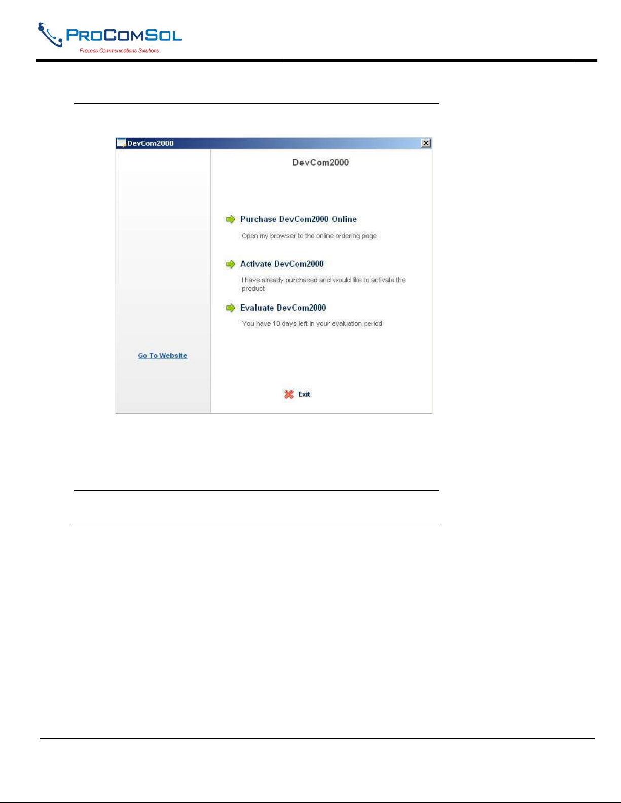
1 Start the DevCom2000 Application. The following Activation
window is displayed:
If you want to evaluate DevCom2000 before purchasing, select
the “Evaluate DevCom2000” option. You will have 10 days of
unlimited program use before you will need to purchase a
license. Select “Purchase DevCom2000 Online” to go to the
ProComSol, Ltd website to purchase a license.
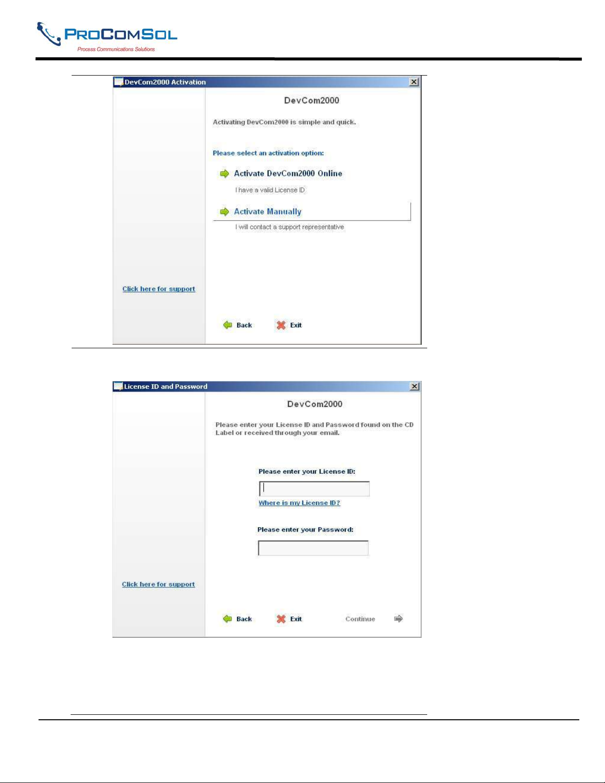
2 If “Activate DevCom2000” is selected, the following window
appears:
MAN-1010 10/21/2021 Providing Advanced Process Communication Page 10
Products Since 2005
Find Quality Products Online at: [email protected]
www.GlobalTestSupply.com
Page 11
DevCom2000 User Manual
3 If the “Activate DevCom2000 Online” option is selected, the
following window appears.
Enter the information from the Activation label on the CD case.
Select “Continue” to process the information.
If the codes were successfully entered, the program will continue
as normal. You will not need to perform the activation process
again.
MAN-1010 10/21/2021 Providing Advanced Process Communication Page 11
Products Since 2005
Find Quality Products Online at: [email protected]
www.GlobalTestSupply.com
Page 12
DevCom2000 User Manual
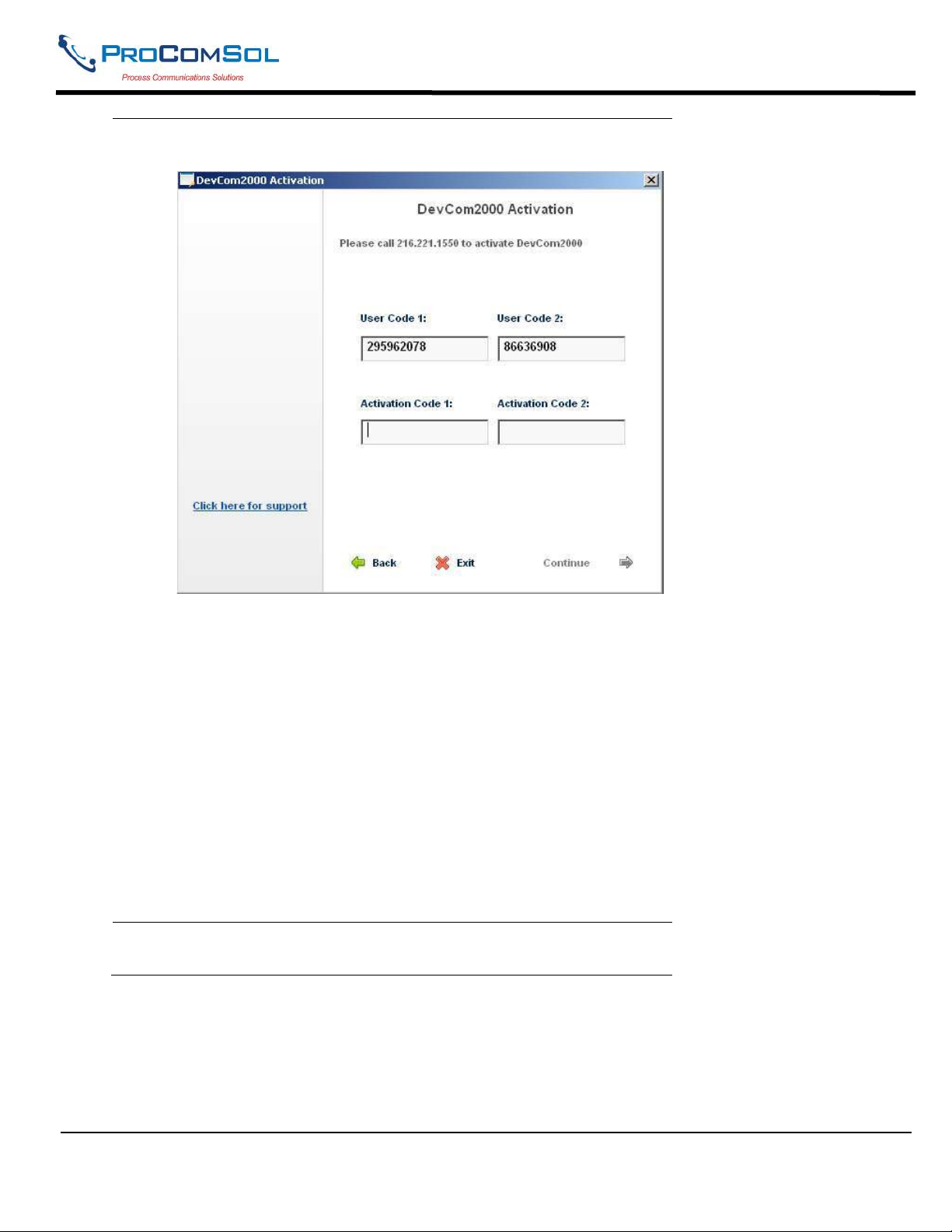
4 If the “Activate Manually” option is selected, the following
window appears:
You will then need to contact ProComSol, Ltd to obtain the
Activation Codes. You must supply the User Codes to
ProComSol, Ltd support personnel (Your user codes will be
different than those shown here). You can register manually in
any of the following ways:
1. Call ProComSol, Ltd at 216.221.1550. Have the LicenseID
and User Codes ready.
2. Or, send an email to containing your
company name, LicenseID, and User Codes.
The above information will be processed at ProComSol, Ltd and
an appropriate response will contain the required Activation
Code information that the user will need to enter.
If successful, the program continues as normal. You will not
need to perform the activation process again.
5 We have tried to make the Activation process as easy as
possible. Contact ProComSol, Ltd if you have any difficulties.
4.4 Connecting to the HART Device
The DevCom2000 application communicates with the HART Field Devices through a HART compatible
communication interface (e.g., a "HART Modem"). Using this communication interface you will transmit real-time
HART data between DevCom2000 and the connected HART compatible field device.
MAN-1010 10/21/2021 Providing Advanced Process Communication Page 12
Products Since 2005
Find Quality Products Online at: [email protected]
www.GlobalTestSupply.com
Page 13
DevCom2000 User Manual
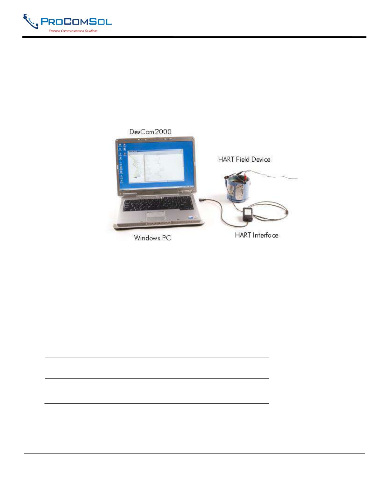
There are a wide variety of HART compatible interfaces. Please follow the manufacturer’s instruction for
connecting your interface to the PC. This manual uses the HART modem manufactured by ProComSol, Ltd, called
the HM-USB-ISO. It uses the USB interface.
Insert the USB connector on the HM-USB-ISO into your computer’s USB port. Using the clips on the wires from
the HART interface, connect to the device across the 4-20ma signal. If a suitable load resistance is not available, a
250 resistor must be placed in series with the device power supply.
Figure 1 Typical DevCom2000 Hardware Setup
4.5 Uninstalling the DevCom2000 Application
To uninstall the DevCom2000 application, perform the following steps:
Step Action
1 Click Start Programs ProComSol DevCom2000
Uninstall DevCom2000
2 Or, Click Start Settings Control Panel Add/Remove
Programs
3 In the Add/Remove Programs dialog window, select the
DevCom2000 program that you want to uninstall.
4 Click Remove.
5 Click OK to confirm the removing of the selected application.
MAN-1010 10/21/2021 Providing Advanced Process Communication Page 13
Products Since 2005
Find Quality Products Online at: [email protected]
www.GlobalTestSupply.com
Page 14
DevCom2000 User Manual
5 USING DEVCOM2000
5.1 Starting DevCom2000
The HART field device must be connected to a PC or tablet running DevCom2000 to configure or calibrate the
field device, or to view the field device's data. Make sure to establish the physical connection between the field
device and the DevCom2000 computer. With the physical connection established, launch DevCom2000 by
clicking the DevCom2000 icon on your desktop. You can also start the application by going to your computer's
Start Menu and selecting Start ProComSol DevCom2000.
If your computer is running an anti-virus program such as McAfee, you may get a message about a program
wanting to access the internet. This is normal. DevCom2000 uses TCP/IP to communicate with the
Communication Log program.
Step Action
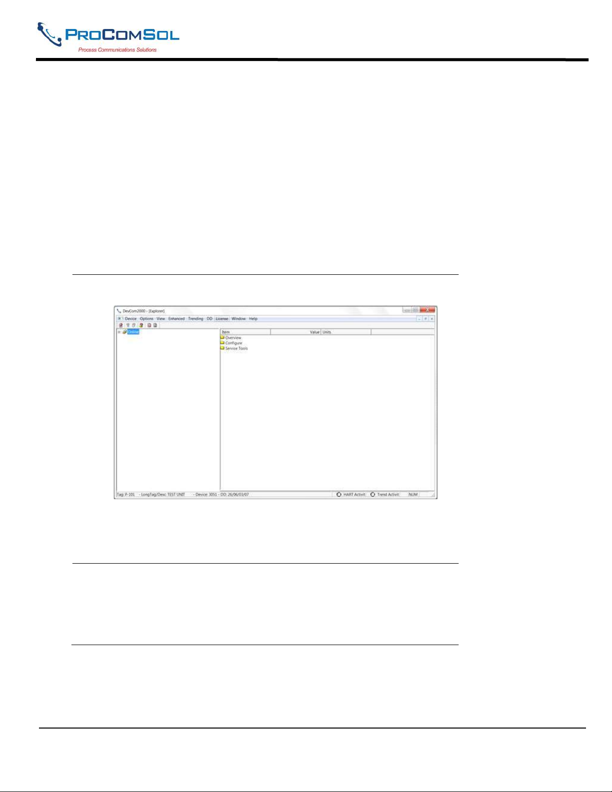
1 Start the DevCom2000 Application. The following application
window is displayed:
DevCom2000 will then automatically identify the field device and
open a communication channel to (i.e., a connection with) the field
device.
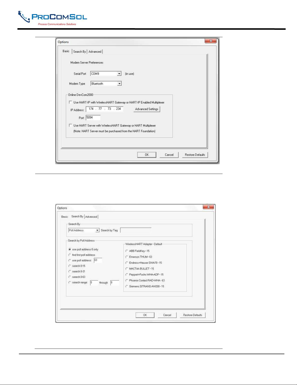
2 Setting Options Options Basic
If communications cannot be established, you may need to change the
communication settings using the Options dialog box.
The serial port box will show the available COM ports. Select the one
your HART modem is using.
MAN-1010 10/21/2021 Providing Advanced Process Communication Page 14
Products Since 2005
Find Quality Products Online at: [email protected]
www.GlobalTestSupply.com
Page 15
DevCom2000 User Manual
Also verify the Modem Type matches your physical modem.
3 You may also change the polling options for the computer. If you do
not know the poll address of the device you are trying to communicate
with, use the default address 0 setting. To do this either click on the
Search By tab or go to OptionsSearch
Make sure that Poll Address under Search By is selected.
MAN-1010 10/21/2021 Providing Advanced Process Communication Page 15
Products Since 2005
Find Quality Products Online at: [email protected]
www.GlobalTestSupply.com
Page 16
DevCom2000 User Manual
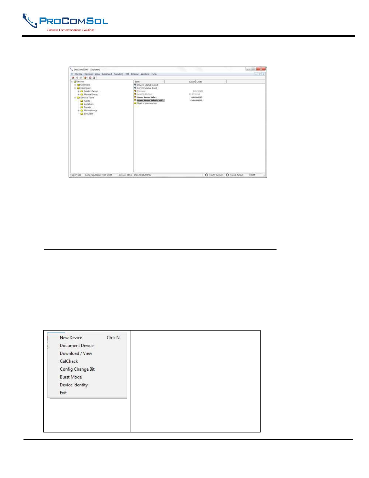
4 When the device is connected to DevCom2000, the browser window
appears with online (i.e. root menu) selected.
The left pane of the window shows the menu structure and the right
pane of the window displays corresponding parameters of the menu
selected.
The DevCom2000 screens shown in this document are only an
example of what you may see when connected to your field device.
What you see is actually controlled by the DD and the device. The
menus, data, status and configurations displayed are specified by the
field device's manufacturer in the DD itself.
5 Select the required menu to configure or review the field device's data.
5.2 Getting Familiarized with DevCom2000 Explorer
5.2.1 Using the Menus
DevCom2000 Explorer provides visual representation and structure of the application window.
Menu Explanation
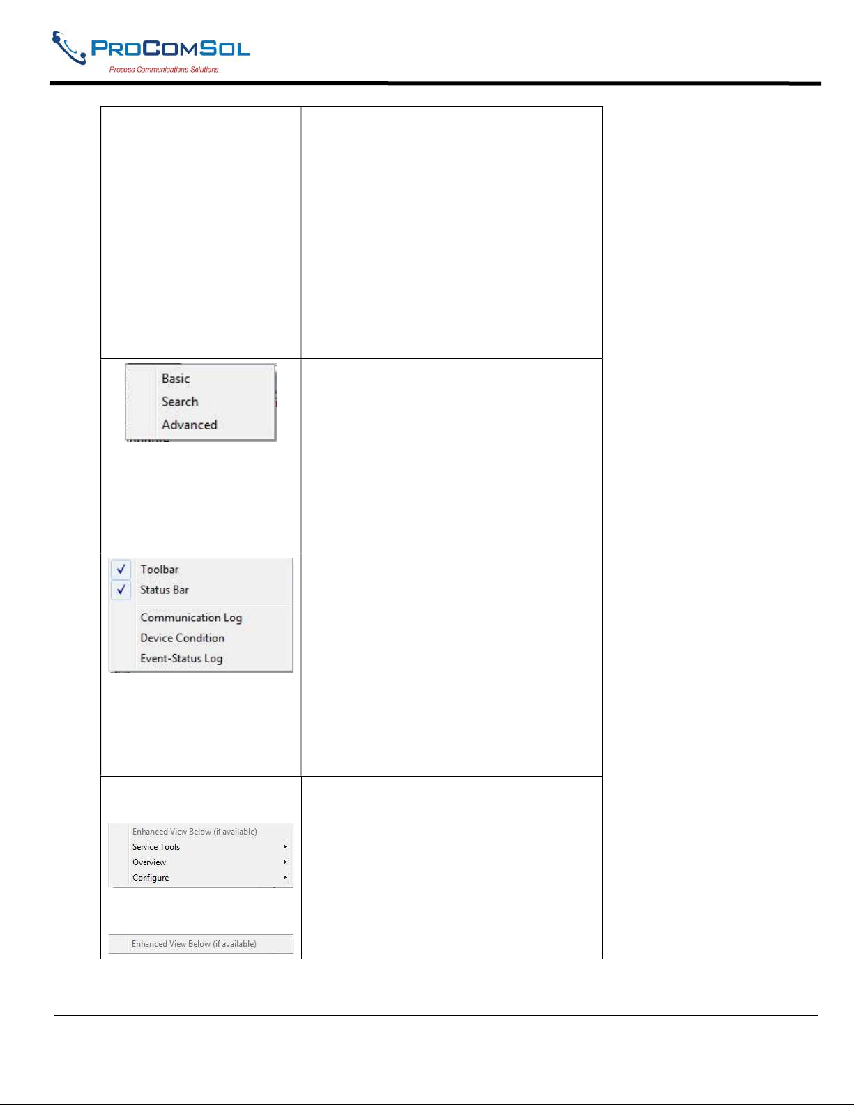
The Device Menu offers the following
sub-menu options:
New Device - Connect to a new device or
reconnect to the same device.
Document Device – Brings up the
Document Device dialog box used to save
the device configuration as a text and pdf
file.
Download / View – Brings up the
Download dialog box which provides
Configuration File features.
MAN-1010 10/21/2021 Providing Advanced Process Communication Page 16
Products Since 2005
Find Quality Products Online at: [email protected]
www.GlobalTestSupply.com
Page 17
DevCom2000 User Manual
CalCheck
- Brings up the Calibration
Check dialog box used to document the
calibration performance of the device.
Config Change Bit - Brings up the
Configuration Change Bit dialog box to
manage this status bit.
Burst Mode - Brings up the Burst Mode
dialog box to enable/disable Burst Mode.
Device Identity - Brings up the Device
Identity dialog box that provides identity
information for the device.
Exit - Exit DevCom2000.
The Options Menu offers the following
sub-menu options:
Basic- Select what COM port the device
is connected to and whether to use a
WirelessHART gateway.
Search- Search by Poll Address, Long or
Short Tag.
Advanced- Select HART Master,
Language, and DD Startup.
Example of available
Enhanced Menus:
No Enhanced Menus
available:
The View Menu offers the following submenu options:
Toolbar - Hide or show the Tool Bar.
Status Bar - Hide or show the Status Bar.
Communication Log – Open the
Communication Log window.
Device Condition – View detailed device
status.
Event-Status Log – View log of events
and status changes
The Enhanced menu offers enhanced
device menus. Some devices do not have
enhanced menus and this menu will only
say “Enhanced View Below (if available).
MAN-1010 10/21/2021 Providing Advanced Process Communication Page 17
Products Since 2005
Find Quality Products Online at: [email protected]
www.GlobalTestSupply.com
Page 18
DevCom2000 User Manual
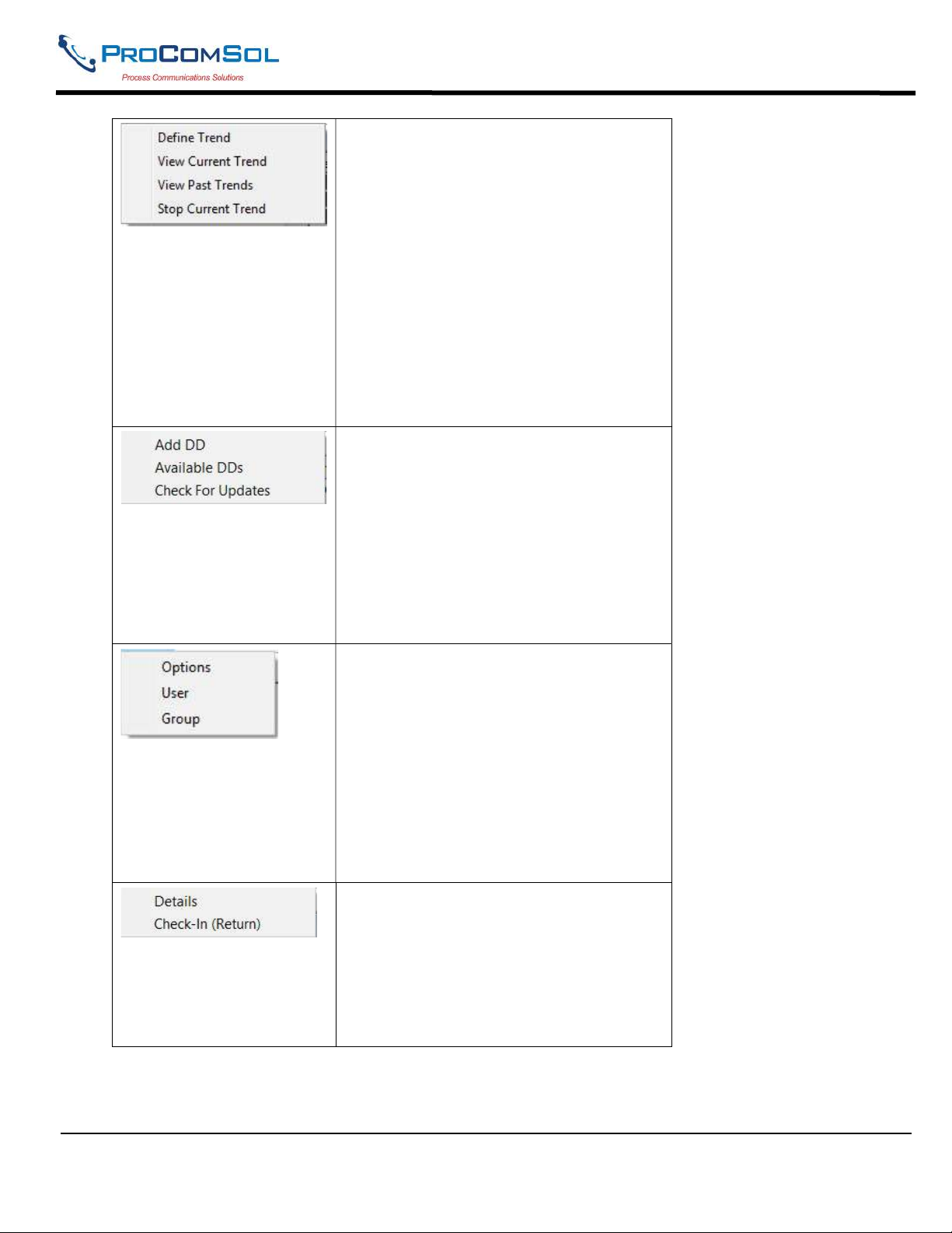
The Trending menu offers the following
sub-menu options:
Define Trend – Brings up the Define
Trend dialog box where a trend is started.
View Current Trend – Brings up a realtime graph of values currently being
trended.
View Past Trends – Brings up the View
Trend dialog which contains past trend
files. Selected trend files can then be
graphed.
Stop Current Trend – Stops the current
log in process.
The DD menu offers the following submenu options:
Add DD – Brings up the dialog that adds
a DD to the library.
Available DDs – Brings up a browser of
all the DDs installed in the library.
Check For Updates – Shows current DD
Library version and checks for DD library
update
The Cloud menu offers the following submenu options (Note that a Cloud
Subscription is required for Cloud
services):
Options - Brings up the Options dialog
box to enable or disable Cloud access.
User - Brings up the User dialog box to
configure the user and cloud access.
Group - Brings up the Group dialog box
to configure Group membership.
The License window offers the following
sub-menu options:
Details – Shows License ID and Password
information.
Check-In (return) – Returns license to
our server and closes program
MAN-1010 10/21/2021 Providing Advanced Process Communication Page 18
Products Since 2005
Find Quality Products Online at: [email protected]
www.GlobalTestSupply.com
Page 19
DevCom2000 User Manual
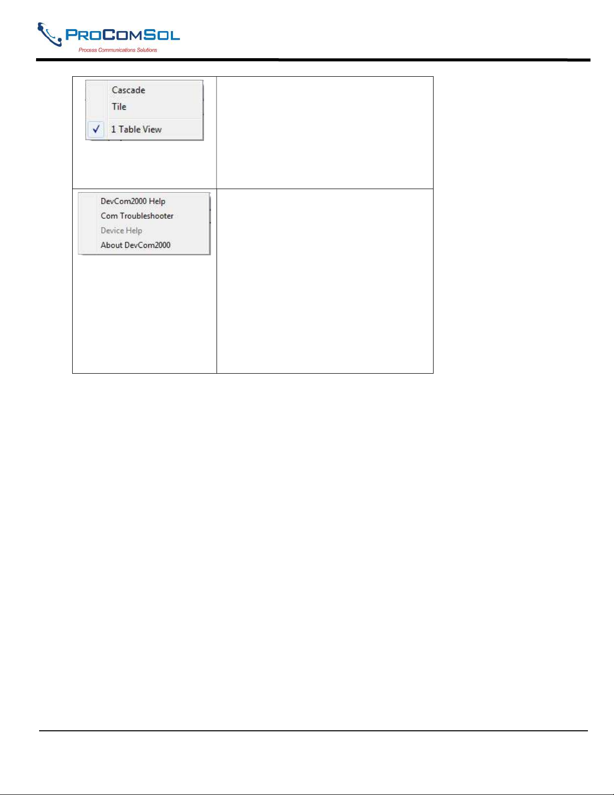
The Window menu offers the following
sub-menu options:
Cascade – Organizes open windows in a
cascade arrangement.
Tile – Organizes open windows as tiles
1 Table View – List of the open windows.
Click to select the window to view
The Help menu offers the following submenu options:
DevCom2000 Help – Brings up Help
information for the DevCom2000
application.
Com Troubleshooter – Brings up the
DevCom2000 Com Troubleshooter.
Device Help – Brings up help information
for the connected device (if available).
About DevCom2000 – Shows copyright
information, support information, and
application Version Number.
5.2.2 Using the Toolbar
When you start the application, by default, the toolbar buttons appears on the main window. If it fails to display,
click View Toolbar option from the menu bar to bring up the toolbar.
MAN-1010 10/21/2021 Providing Advanced Process Communication Page 19
Products Since 2005
Find Quality Products Online at: [email protected]
www.GlobalTestSupply.com
Page 20
DevCom2000 User Manual
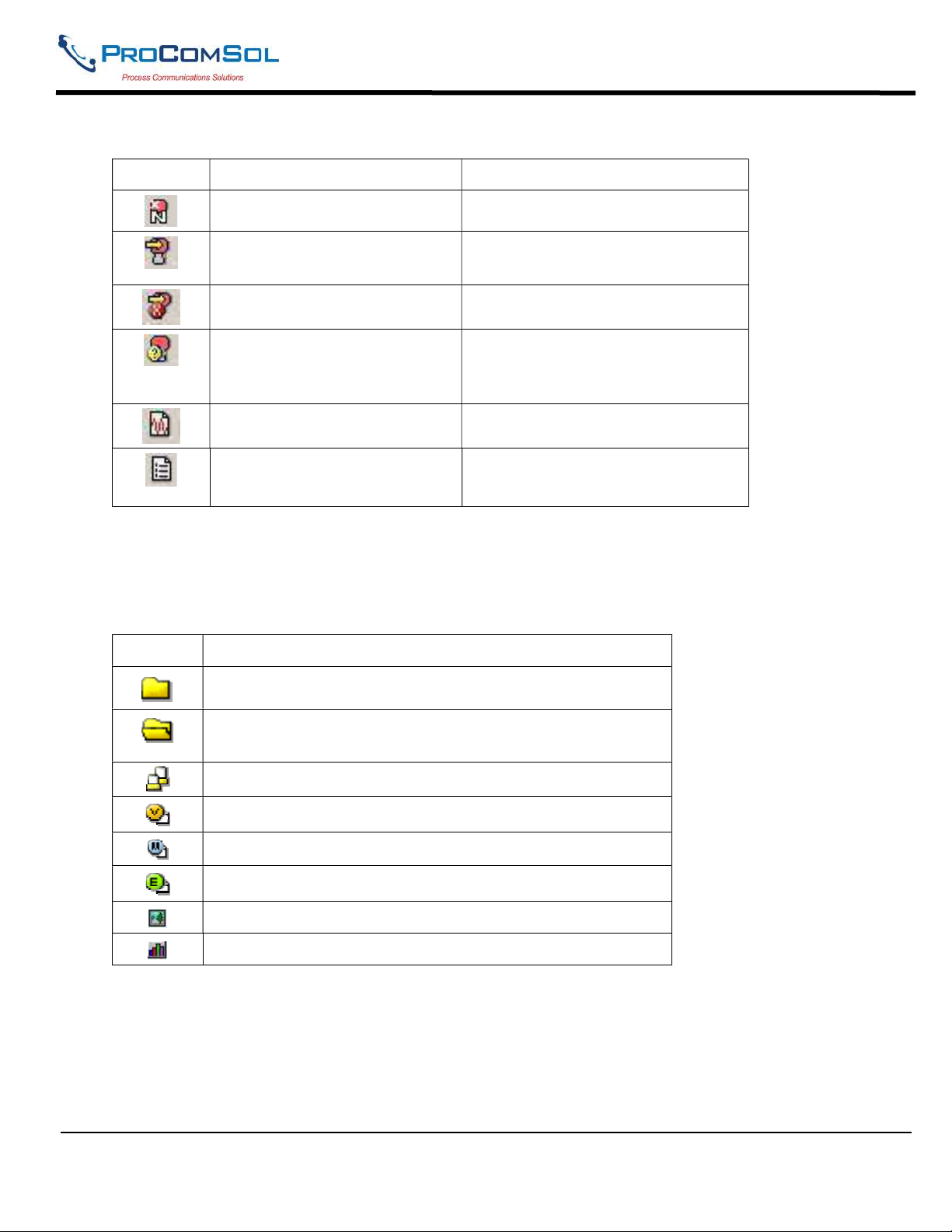
Following are the buttons available in the DevCom2000 application toolbar to perform the necessary tasks:
Button Description Corresponding Menu Option
Connect to a new device
Device New Device
Send parameter changes to the
device
Cancel parameter changes
View more status on Device
and Communication
View Device Condition
(Command 48 status)
View Communication log View Communication log
View Event log
View Event-Status log
5.2.3 Icons
DevCom2000 application uses different icons to represent different elements of the application. Following table
lists the icons and their meanings:
Icon Meaning
Indicates a menu or submenu in the navigation tree
Indicates a currently selected menu or submenu in the
navigation tree
Online menu icon. The actual DD menu comes under this.
Indicates a “Variable” item
Indicates a “Method” (Standard Operating Procedure) item
Indicates an “Edit Display” item
Indicates an “Image” item
Indicates a “Graph” item
MAN-1010 10/21/2021 Providing Advanced Process Communication Page 20
Products Since 2005
Find Quality Products Online at: [email protected]
www.GlobalTestSupply.com
Page 21

DevCom2000 User Manual
6 FUNCTIONS AND BASIC OPERATIONS
6.1 Overview
DevCom2000 allows the user to monitor and configure a single device at a time in the field. Each device is
associated with the DD when the device information is present. A DD may contain any of the following
parameters/elements:
Variable
A variable is defined as the data contained in the device (e.g. Device Firmware Version). There are two types of
variables:
Editable Variable – It allows the operator to modify the value and download it to the device.
Non-Editable Variable – It is a read-only data from the device.
Edit Display
This option is used to view a group of parameters. You can also modify a single parameter from this group, based
on which other parameters of the device get altered.
For example, if the Engineering Unit of the device is modified, the corresponding Low Limits and High Limits
change as per the Engineering Unit set.
Method / Standard Operating Procedure (SOP)
This option helps to perform various tests on the device for instance, Self Test and Loop Test. A Method or SOP is
a series of steps that are executed in a sequence results in the completion of some device related tasks. When a
method gets invoked, it gives various warning messages and options to the user, by which the user can thoroughly
test the device. If a test is aborted by operator command at any stage of the sequence, the method invokes
additional steps to bring the device back to its original state before the test.
6.2 Viewing Device Configuration (typical, actual view may change based on DD)
To view the configuration of the device that is connected to DevCom2000, perform the following steps:
Step Action
1 Ensure that the application is running and communications have
been established:
MAN-1010 10/21/2021 Providing Advanced Process Communication Page 21
Products Since 2005
Find Quality Products Online at: [email protected]
www.GlobalTestSupply.com
Page 22
DevCom2000 User Manual
Step Action
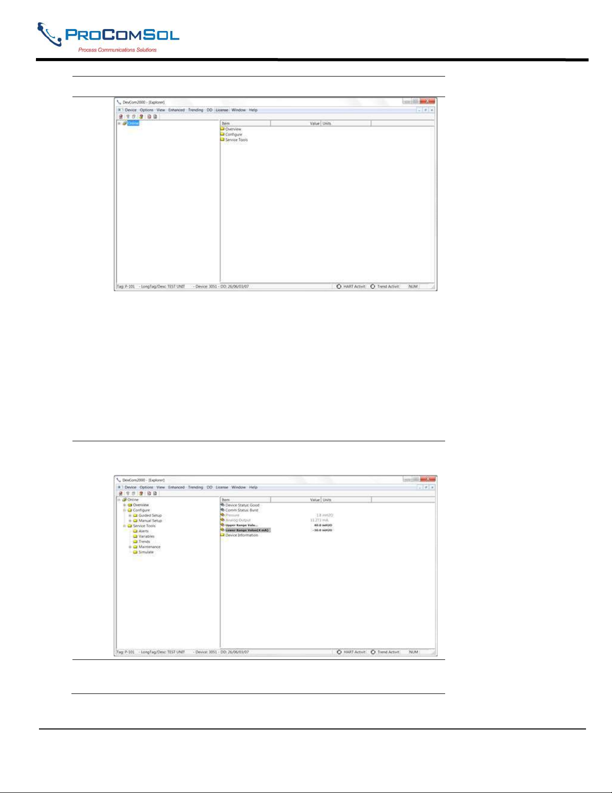
The left pane of the window shows the menu structure and the right
pane of the window displays corresponding parameters of the menu
selected.
The menus are displayed depending on the type of device that is
being connected. These menus are displayed based on the DD file
of the particular device.
If no DD is available for the device the DevCom2000 will select
the standard DD. This should provide limited functionality for the
device. NOTE: If a parameter is updated that is not supported by
the device you will receive an error.
2 Expand the menu by clicking the “+” sign and double-click to view
the device parameters. Below is an example of an expanded menu:
3 Select the menu and view the associated parameters to view the
device information.
MAN-1010 10/21/2021 Providing Advanced Process Communication Page 22
Products Since 2005
Find Quality Products Online at: [email protected]
www.GlobalTestSupply.com
Page 23
DevCom2000 User Manual
6.3 Configuring Device Information
6.3.1 Overview
DevCom2000 allows you to view and configure the field device parameters based on the device description.
However, the device vendor defines most of the parameters at the factory. These parameters become read only
for the users and the user cannot modify the values. The related variables are grouped under various menus of
different levels as defined in the DD file. Expand or collapse the tree view using the “+” or “-“sign to access
the device configuration parameters.
Following table describes the details about the device configuration:
Step Action
1 Ensure that the application is running and communications have
been established:
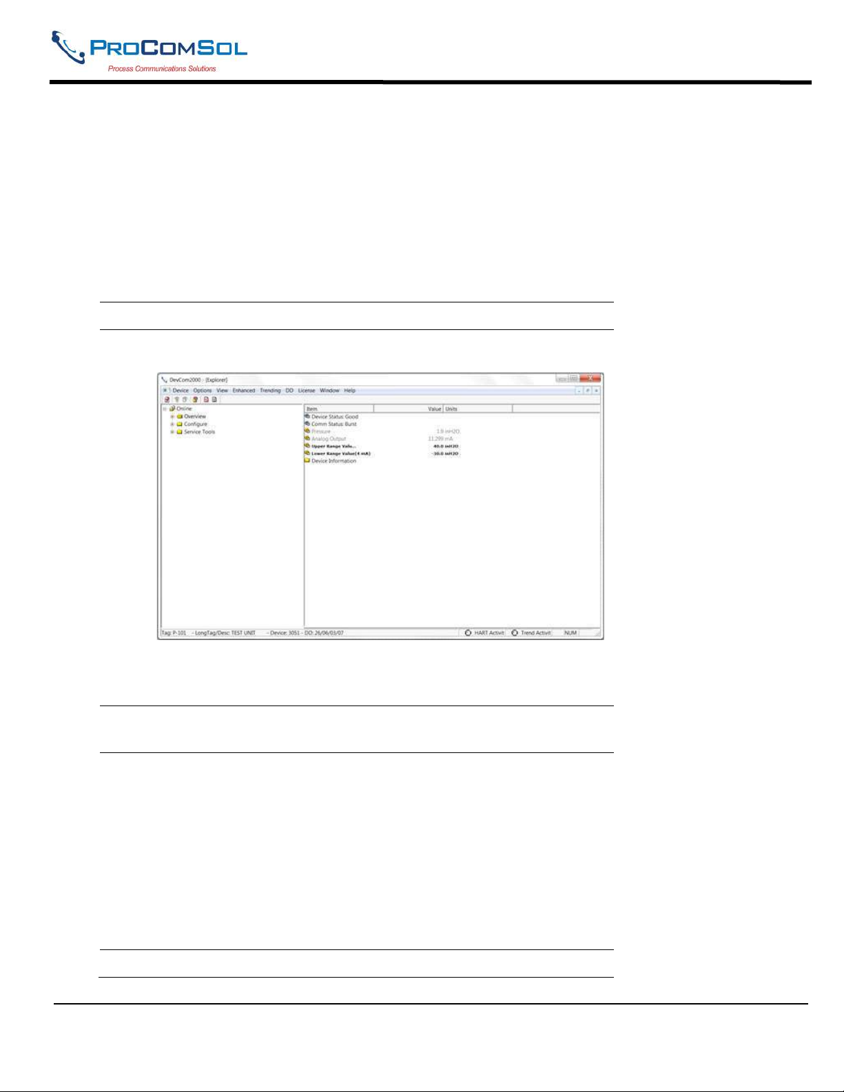
The left pane of the window shows the menu structure and the right
pane of the window displays corresponding parameters of the menu
selected.
2 Expand the menu by clicking the “+” sign and double-click to view
the device parameters.
3 There are three types of variables: dynamic, read/write and read
only. The parameters that are grayed out indicate that these are
dynamic variables (variables that get updated online by the device)
or read only variables.
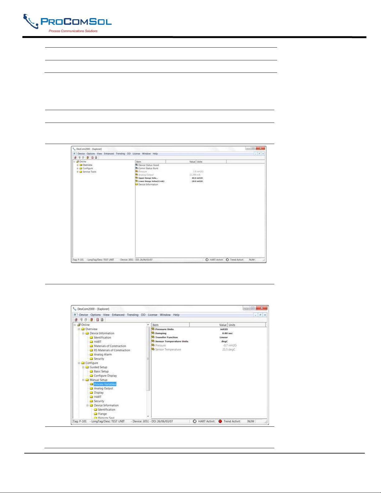
Following points describe how the device parameters represents
their status when connected to DevCom2000:
Bold Font: Modifiable Values
Normal Font: Menu Item
Gray Font: Dynamic or Read Only Variables
4 Select the parameter and configure the values, as required.
MAN-1010 10/21/2021 Providing Advanced Process Communication Page 23
Products Since 2005
Find Quality Products Online at: [email protected]
www.GlobalTestSupply.com
Page 24
DevCom2000 User Manual
Step Action
5 The subsequent topics explain how to configure device parameters.
6.3.2 Variable
To edit the parameter variables of the connected device, perform the following steps:
Step Action
1 Ensure that the application is running and communications have
been established:
Expand the menu by clicking the “+” sign and double-click to
view the device parameters.
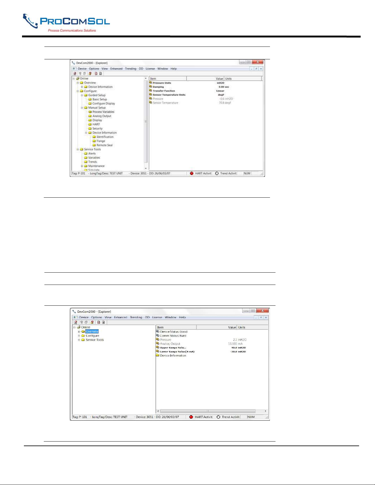
2 Select the menu where the editable parameter is present as shown
below:
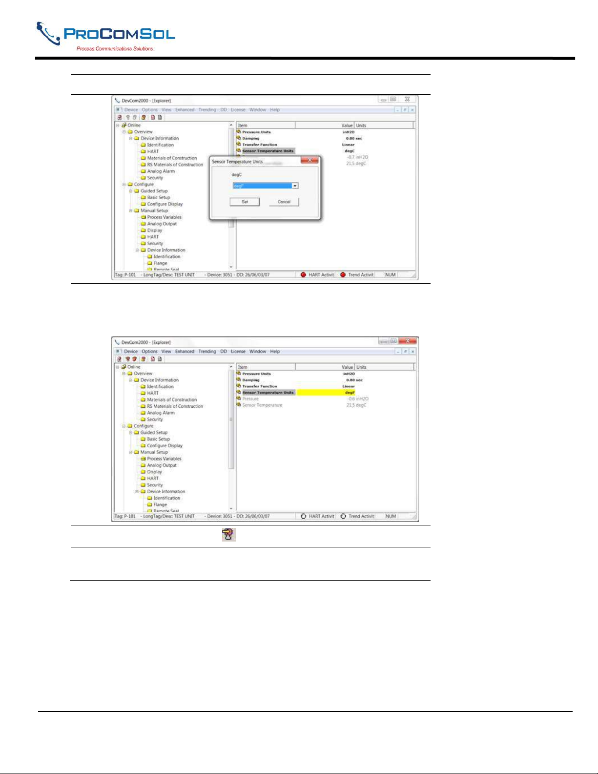
3 Double-click the variable to edit it. The following dialog box
appears on the screen:
MAN-1010 10/21/2021 Providing Advanced Process Communication Page 24
Products Since 2005
Find Quality Products Online at: [email protected]
www.GlobalTestSupply.com
Page 25
DevCom2000 User Manual
Step Action
4 Make the changes to the parameter value, as required.
5 Click Set to accept the changed value. The change gets reflected
as shown:
6
Click on the Send icon to commit the changes to the device.
7 When the value is no longer yellow, the variable has been changed
in the device.
MAN-1010 10/21/2021 Providing Advanced Process Communication Page 25
Products Since 2005
Find Quality Products Online at: [email protected]
www.GlobalTestSupply.com
Page 26
DevCom2000 User Manual
Step Action
The Send and Cancel Icon will now be grey as well. This indicates
that there are no new changes to be sent to the device.
6.3.3 Edit Display
The Edit Display is a variation on the Variable edit. An additional window helps the user view a group of
parameters based on the DD. You can also modify a single parameter from this group. Parameters linked to
the edited field will be updated automatically
To view and configure these variables, perform the following steps:
Step Action
1 Ensure that the application is running and communications have
been established
Expand the menu by clicking the “+” sign and double-click to view
the device parameters.
MAN-1010 10/21/2021 Providing Advanced Process Communication Page 26
Products Since 2005
Find Quality Products Online at: [email protected]
www.GlobalTestSupply.com
Page 27
DevCom2000 User Manual
Step Action
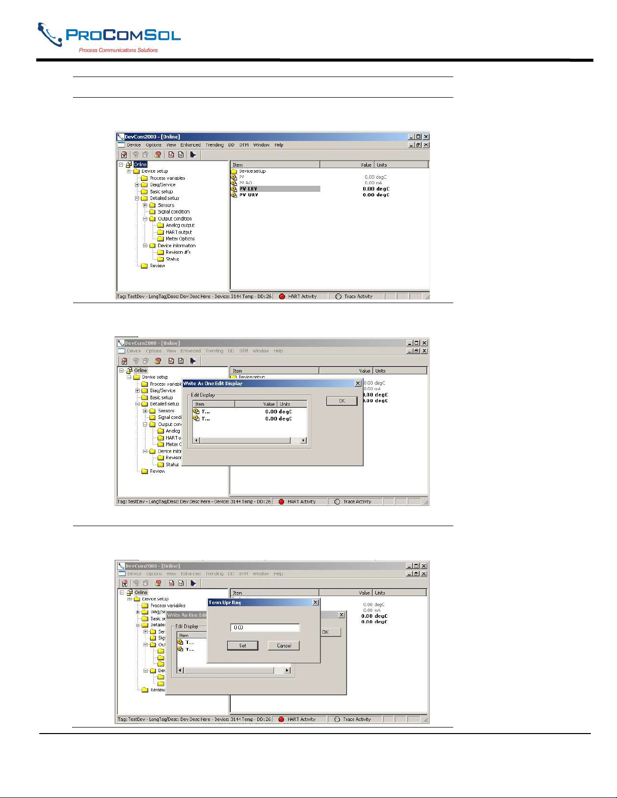
2 Select the menu where the required variable is present as shown
below:
3 Double click the parameter you wish to edit. The following dialog
box appears on the screen:
4 Double click the parameter you wish to edit. The following dialog
box appears on the screen:
MAN-1010 10/21/2021 Providing Advanced Process Communication Page 27
Products Since 2005
Find Quality Products Online at: [email protected]
www.GlobalTestSupply.com
Page 28
DevCom2000 User Manual
Step Action
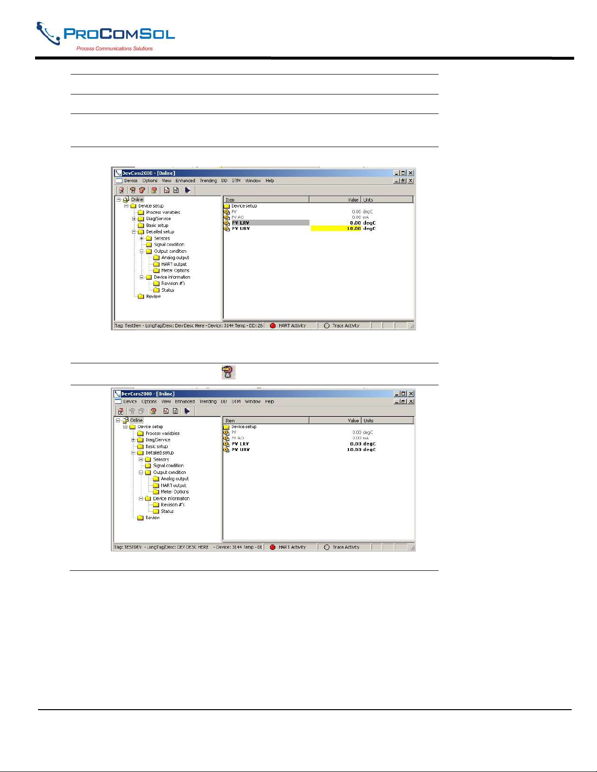
5 Make the change to the value, as required.
6 Click Set to accept the changes. Or press Cancel to cancel the
changes.
7 Click OK to close the dialog box.
Again the yellow means the parameter is changed and ready to be
sent to the device.
8
Click on the Send icon to commit the changes to the device.
9
After being sent the change is reflected in the device info.
6.3.4 Executing Methods or Standard Operating Procedures
Methods are defined in the DD file for the device that DevCom2000 is connected to. You can select the
Method and execute it for calibrating the device, trouble shooting, etc. Method execution leads you through a
number of steps, like in a wizard.
MAN-1010 10/21/2021 Providing Advanced Process Communication Page 28
Products Since 2005
Find Quality Products Online at: [email protected]
www.GlobalTestSupply.com
Page 29
DevCom2000 User Manual
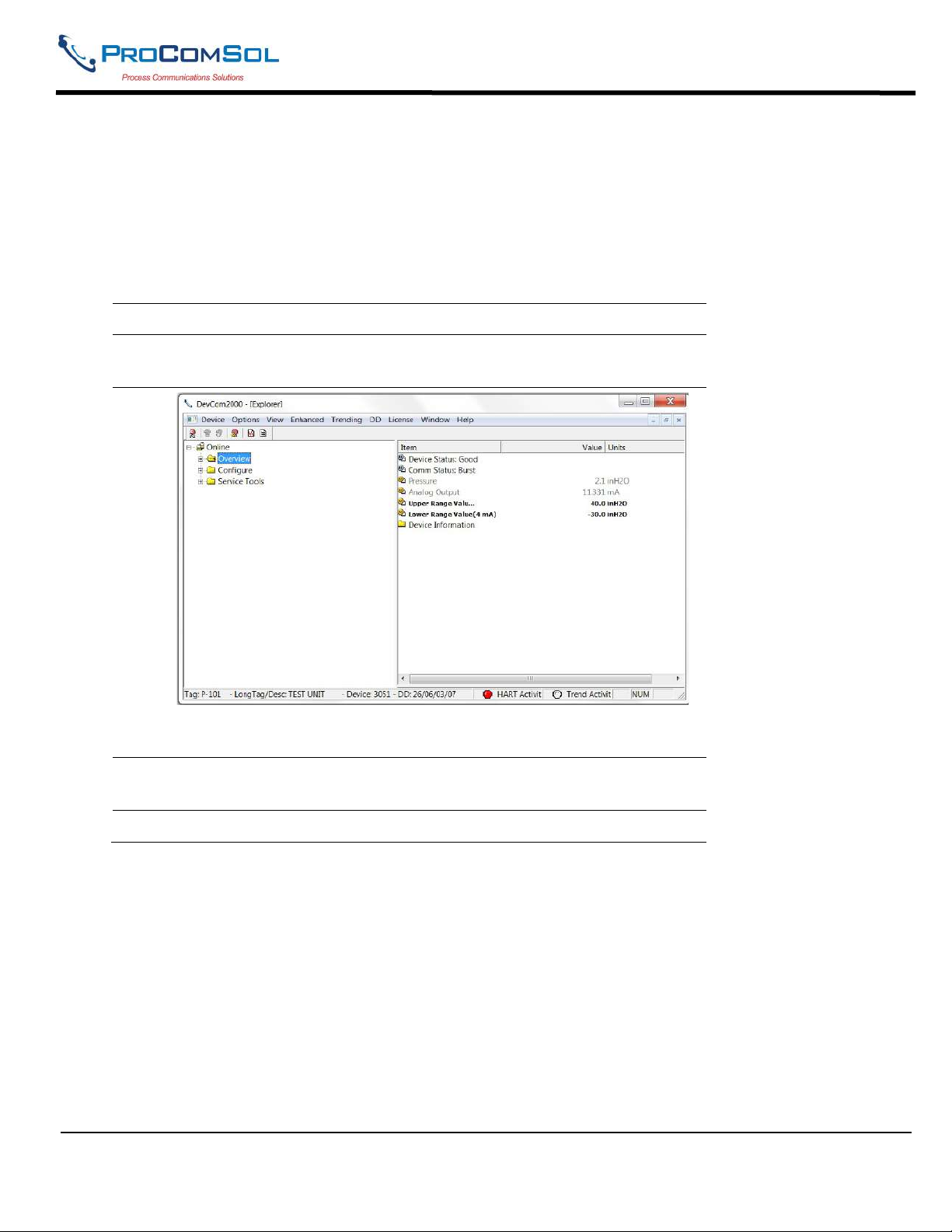
A Few examples of methods include:
- Setting high and low range calibration points
- Calibration of the device
- Run the advanced diagnostic test procedure
- Execute tests to gather information on device operation.
To execute a Method, perform the following steps:
Step Action
1 Ensure that the application is running and communications have been
established:
Expand the menu by clicking the “+” sign and double-click to view
the device parameters.
2 Select the menu where the method is present and double-click to
execute it.
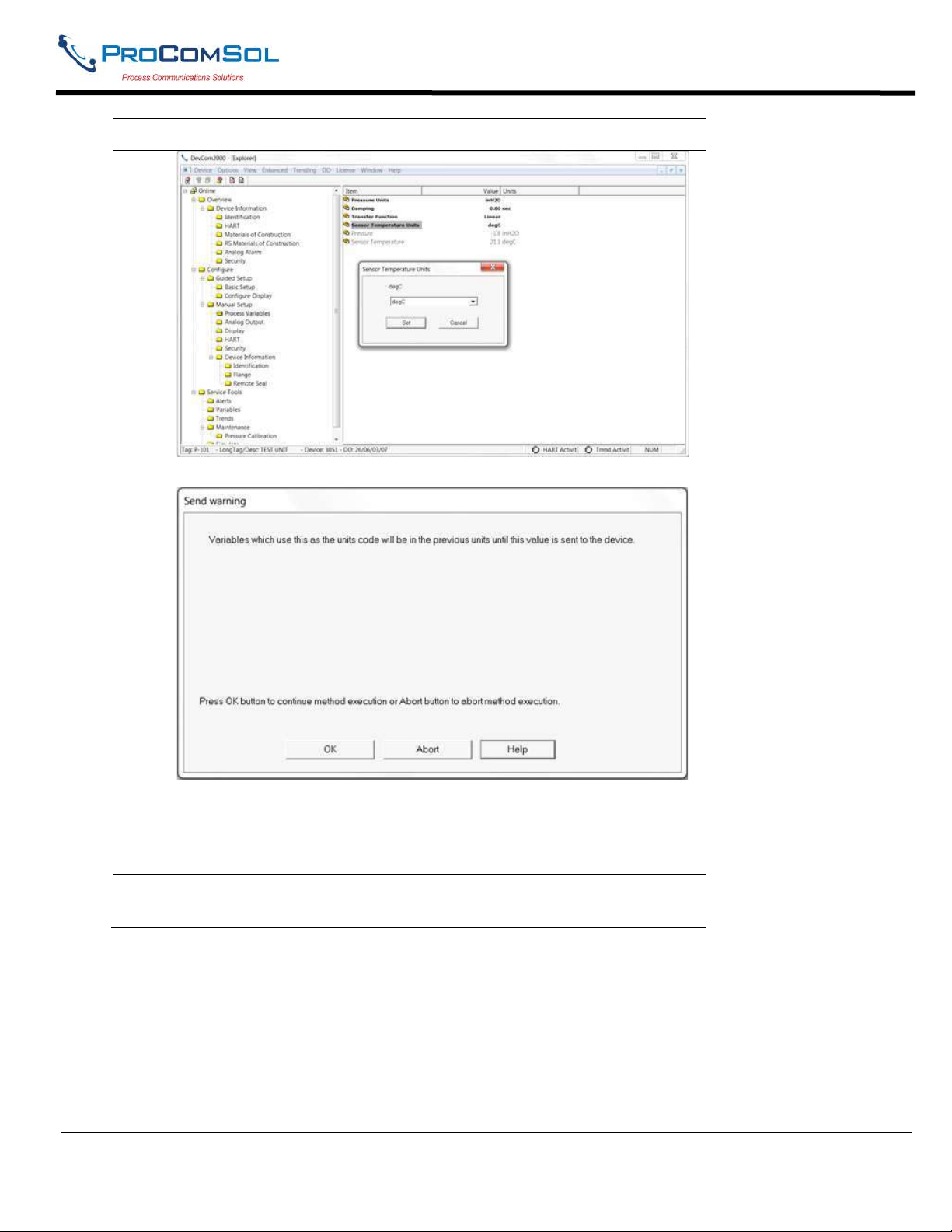
3 Below is an example of a Method dialog box:
MAN-1010 10/21/2021 Providing Advanced Process Communication Page 29
Products Since 2005
Find Quality Products Online at: [email protected]
www.GlobalTestSupply.com
Page 30
DevCom2000 User Manual
Step Action
Click Set to open a Method dialog box:
4 Click OK to move to the next dialog in the Method sequence.
5 Or, click Abort to cancel the Method execution.
6 Click Help to get specific help for that step of the Method. This
Help information is provided by the device DD.
6.4 Calibrating HART Field Devices
Calibration of field devices and loop test are achieved by executing the Methods or Standard Operating Procedures
that are specific to device. Methods are defined based on the test parameters specific to the device, providing
information for the calibration of that device.
See the previous section for Method execution.
MAN-1010 10/21/2021 Providing Advanced Process Communication Page 30
Products Since 2005
Find Quality Products Online at: [email protected]
www.GlobalTestSupply.com
Page 31
DevCom2000 User Manual
6.5 Viewing the Device Status
DevCom2000 provides the user with the ability to monitor the device specific status of the device and the
communication network.
When there is error communicating with the device, it is recognized and indicated to the user. The user can view
more details of such errors, using the View Device Condition from the main window.
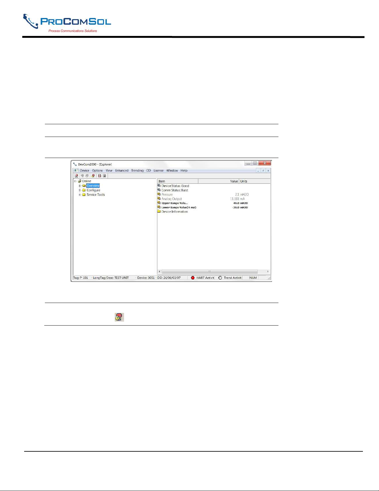
To view the device and communication status, perform the following steps:
Step Action
1 Ensure that the application is running and communications have
been established:
2
Expand the menu by clicking the “+” sign and double-click to view
the device parameters.
3 Select View Device Condition from the main window or choose
the status icon from the toolbar. Following window is displayed:
MAN-1010 10/21/2021 Providing Advanced Process Communication Page 31
Products Since 2005
Find Quality Products Online at: [email protected]
www.GlobalTestSupply.com
Page 32
DevCom2000 User Manual
Step Action
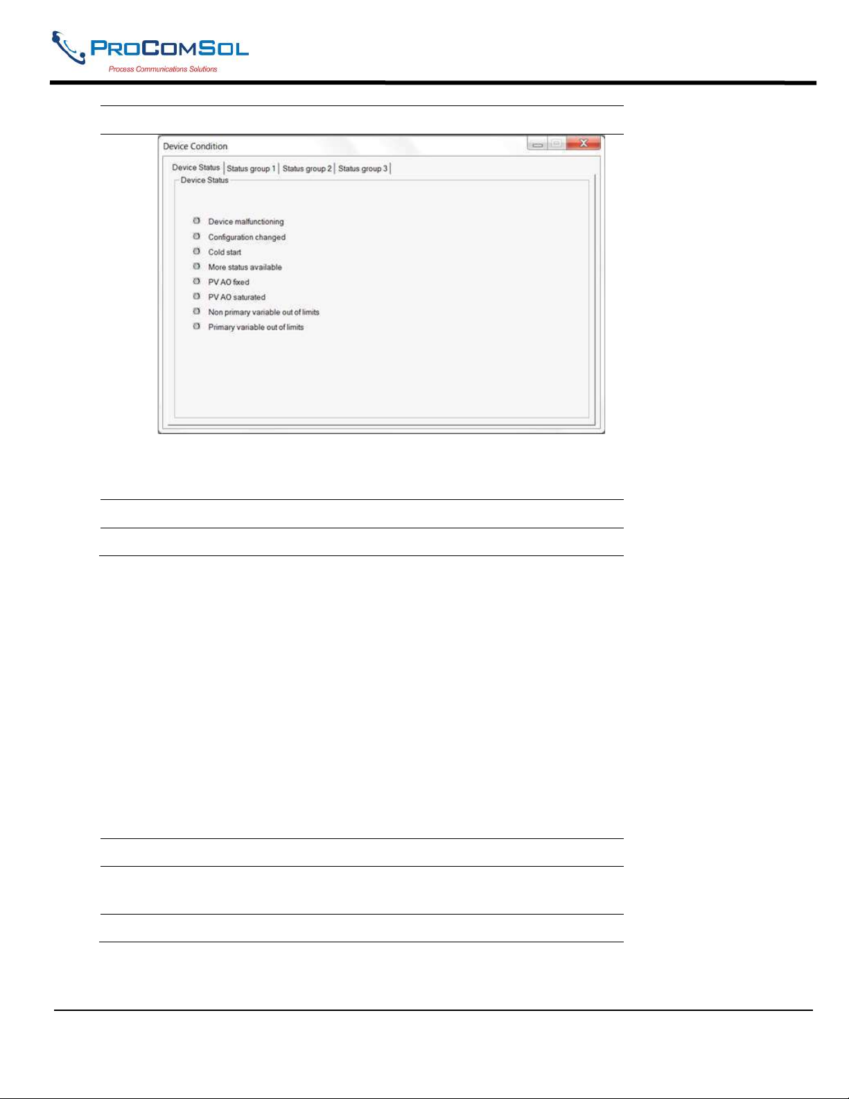
The Device Status tab option shows the status of the device and the
communication network. The individual status is indicated by green
and red LEDs.
4 Additional tabs may be available depending on the DD.
5 Click X to close the Status window.
6.6 Viewing the Communication Log
DevCom2000 allows the user to view the actual communications between DevCom2000 and the device. You can
view send commands and received responses.
If your computer is running an anti-virus program such as McAfee, you may get a message about a program
wanting to access the internet when you open the Communication Log. This is normal. DevCom2000 uses TCP/IP
to communicate with the Communication Log program.
If no data appears in the Communication Log, this may be due to an anti-virus program. Close the Log window and
re-launch.
To view the communication log, perform the following steps:
Step Action
1 Ensure that the application is running and communications have
been established
MAN-1010 10/21/2021 Providing Advanced Process Communication Page 32
Products Since 2005
Find Quality Products Online at: [email protected]
www.GlobalTestSupply.com
Page 33
DevCom2000 User Manual
Step Action
Expand the menu by clicking the “+” sign and double-click to view
the device parameters.
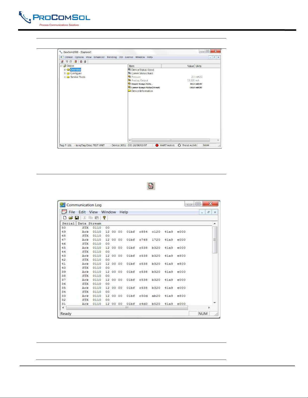
2 Select View Communication Log from the main window or
choose the communications log icon from the toolbar.
Following window is displayed:
Note: The communications log lists actual HART commands and
the responses from the unit. A good understanding of the HART
protocol is required to interpret this data.
3 Select File Exit to get back to the main window. Or, close the
Communication Log window by clicking on the X.
MAN-1010 10/21/2021 Providing Advanced Process Communication Page 33
Products Since 2005
Find Quality Products Online at: [email protected]
www.GlobalTestSupply.com
Page 34
DevCom2000 User Manual
6.7 Viewing the Event-Status Log
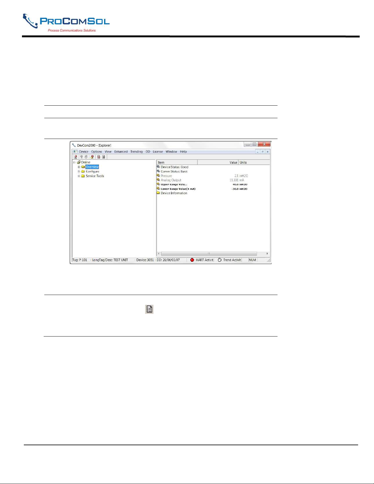
DevCom2000 allows the user to view the error conditions of the device and the communication network.
To view the Event-Status Log, perform the following steps:
Step Action
1 Ensure that the application is running and communications have been
established:
Expand the menu by clicking the “+” sign and double-click to view
the device parameters.
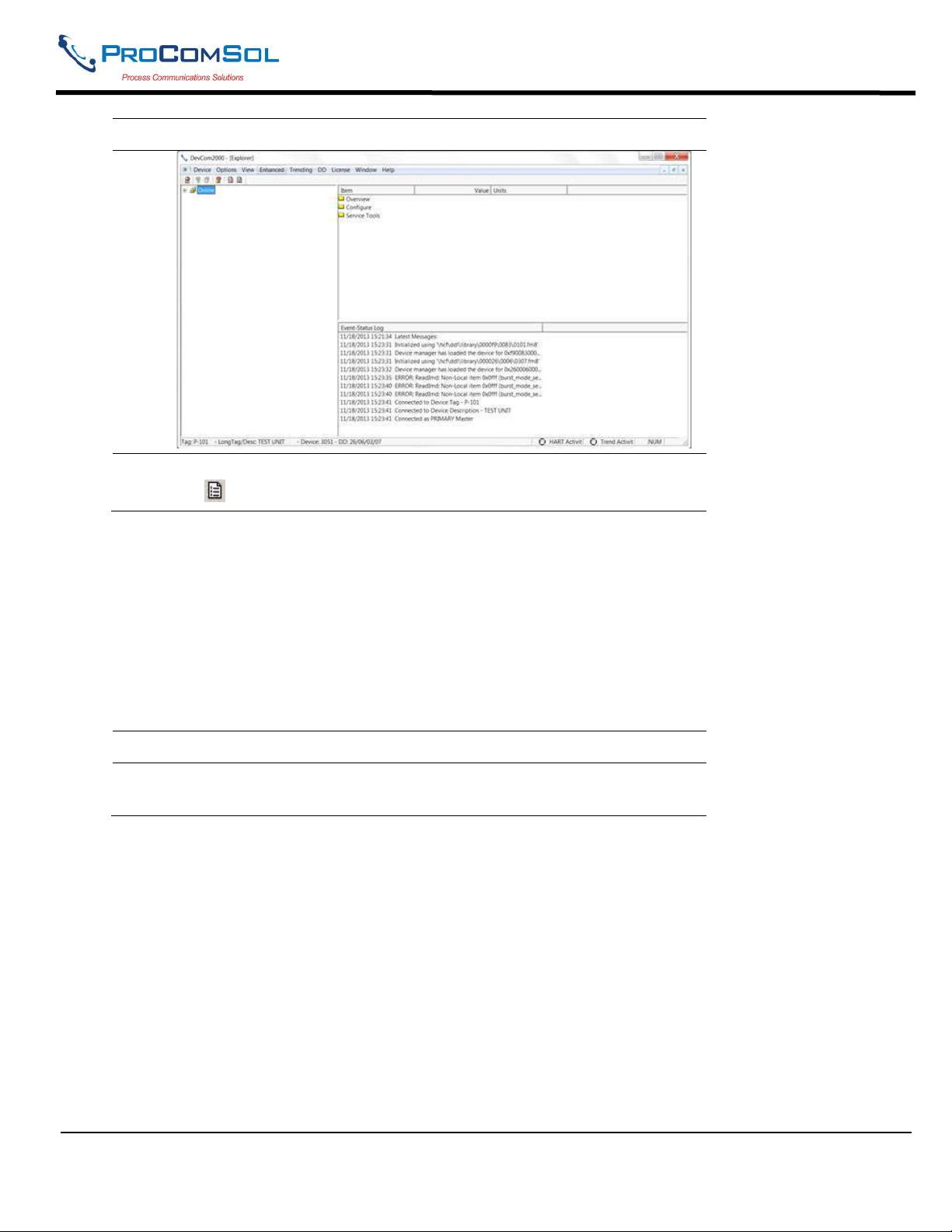
2 Select View Event-Status Log from the main window or choose
the Event-Status log icon from the toolbar. An additional Event
Status window is displayed:
MAN-1010 10/21/2021 Providing Advanced Process Communication Page 34
Products Since 2005
Find Quality Products Online at: [email protected]
www.GlobalTestSupply.com
Page 35
DevCom2000 User Manual
Step Action
3 To close, go to View Event-Status Log menu option or click on
the icon to go back to the original window.
6.8 Document Device Functions
6.8.1 Saving Device Configuration to Disk
HART Device configurations can be saved to disk as a text file to document the device. Fields are delimited
with a comma so that the data can be imported into configuration management software packages. A PDF
version of the configuration is also created.
To save device configurations to disk, perform the following steps:
Step Action
1 Ensure that the application is running and communications have been
established:
MAN-1010 10/21/2021 Providing Advanced Process Communication Page 35
Products Since 2005
Find Quality Products Online at: [email protected]
www.GlobalTestSupply.com
Page 36
DevCom2000 User Manual
Step Action
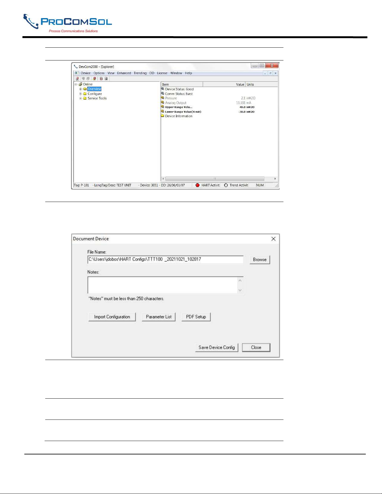
2 Select Device Document Device from the main window. The
Document Device Dialog Box is displayed:
3 The default directory is based on Windows User Accounts. The
default file name is Tag_Date_Time. The directory and filename can
be changed by the user. Use the “Browse” button to change
directories and/or filenames also.
4 Enter a Note in the Notes: field if desired. Maximum of 250
characters.
5 Import Configuration, Parameter List, and PDF Setup are described
below.
MAN-1010 10/21/2021 Providing Advanced Process Communication Page 36
Products Since 2005
Find Quality Products Online at: [email protected]
www.GlobalTestSupply.com
Page 37
DevCom2000 User Manual
Step Action
6 Press the “Save Device Config” button to save device configuration.
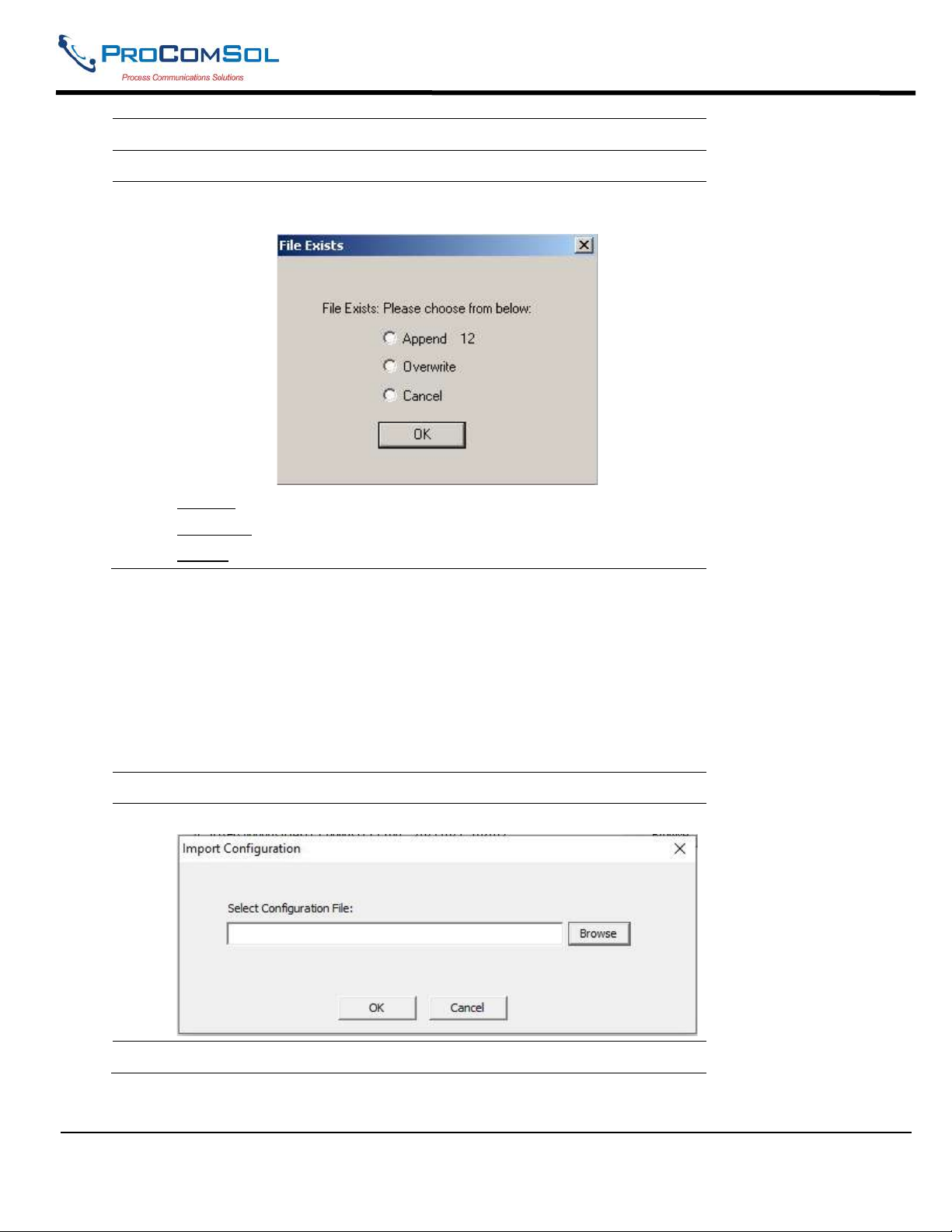
7 If the filename has already been used, the following Dialog Box is
displayed when Save Device Config is pressed:
Append: Adds the number shown to the end of the file name
Overwrite: Deletes and writes over the existing file
Cancel: Returns to the previous menu
6.8.2 Import Configuration Data from Emerson Hand held
HART Device configurations can be imported from files saved by an Emerson 375, 475, or Trex. This
function takes the input .hcf file and converts it to the ProComSol format. This is just like if DevCom2000
was connected to the instrument and saved the configuration. The imported configuration is added to the local
data base and can be viewed, downloaded, etc.
To import a hand held configuration file, perform the following steps:
Step Action
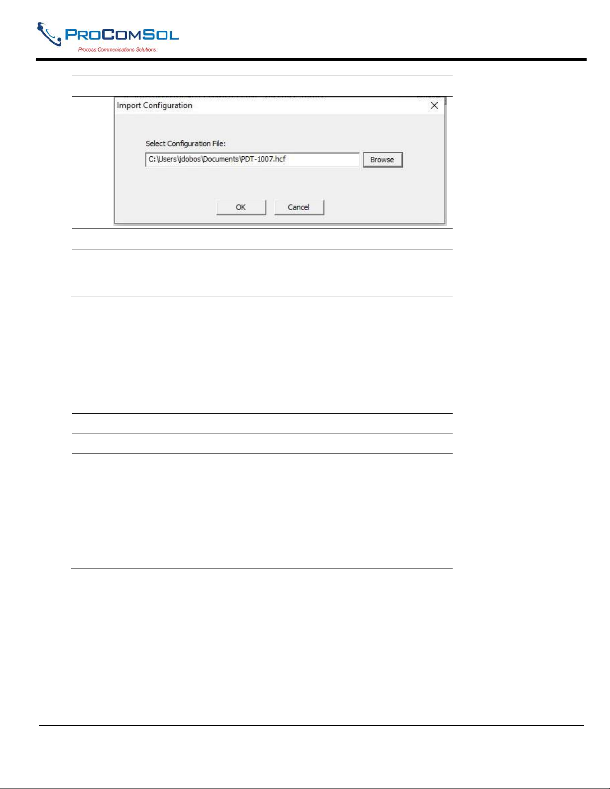
1 Click “Import Configuration”. The following dialog box appears:
2 Click “Browse” to select the .hcf file to import.
MAN-1010 10/21/2021 Providing Advanced Process Communication Page 37
Products Since 2005
Find Quality Products Online at: [email protected]
www.GlobalTestSupply.com
Page 38
DevCom2000 User Manual
Step Action
3 Click “OK” to perform the import.
4 The imported file uses the Tag information, Date, and Time to create
a filename. The text file and pdf files are created. When done, the
pdf file is displayed.
6.8.3 Create Parameter List
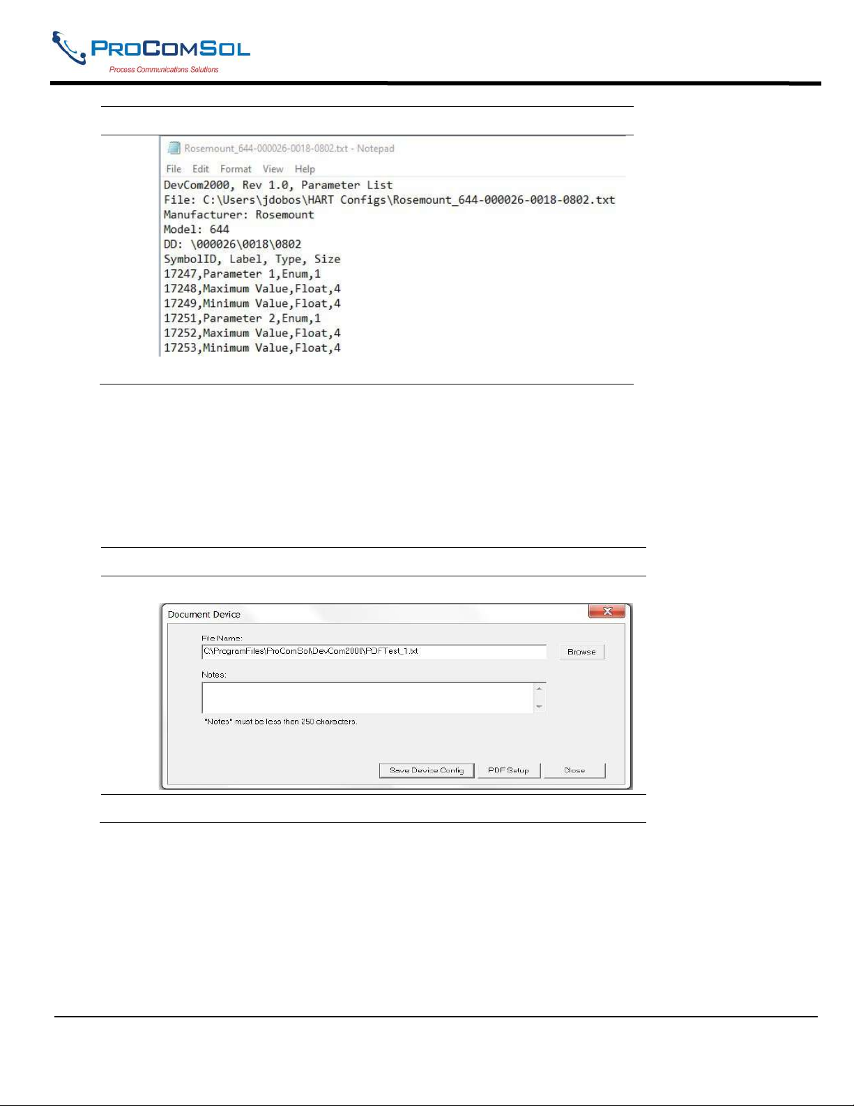
The HART Device parameter list can be extracted from the device and saved to a text file. This information is
useful for the VirtualDevCom Lab View library. The symbol ID, symbol Label, symbol type, and symbol size
information are extracted for the connected device. This information is saved in a text file.
To extract the parameter list, perform the following steps:
Step Action
1 Click “Parameter List”.
2 The parameter list is created and saved to a file. The parameter list
filename consists of the device manufacturer name, the model, and
the DD file code. It is a text file.
The resulting text file is opened when complete.
Here is a partial example:
MAN-1010 10/21/2021 Providing Advanced Process Communication Page 38
Products Since 2005
Find Quality Products Online at: [email protected]
www.GlobalTestSupply.com
Page 39
DevCom2000 User Manual
Step Action
6.8.4 Setup PDF Header and Footer
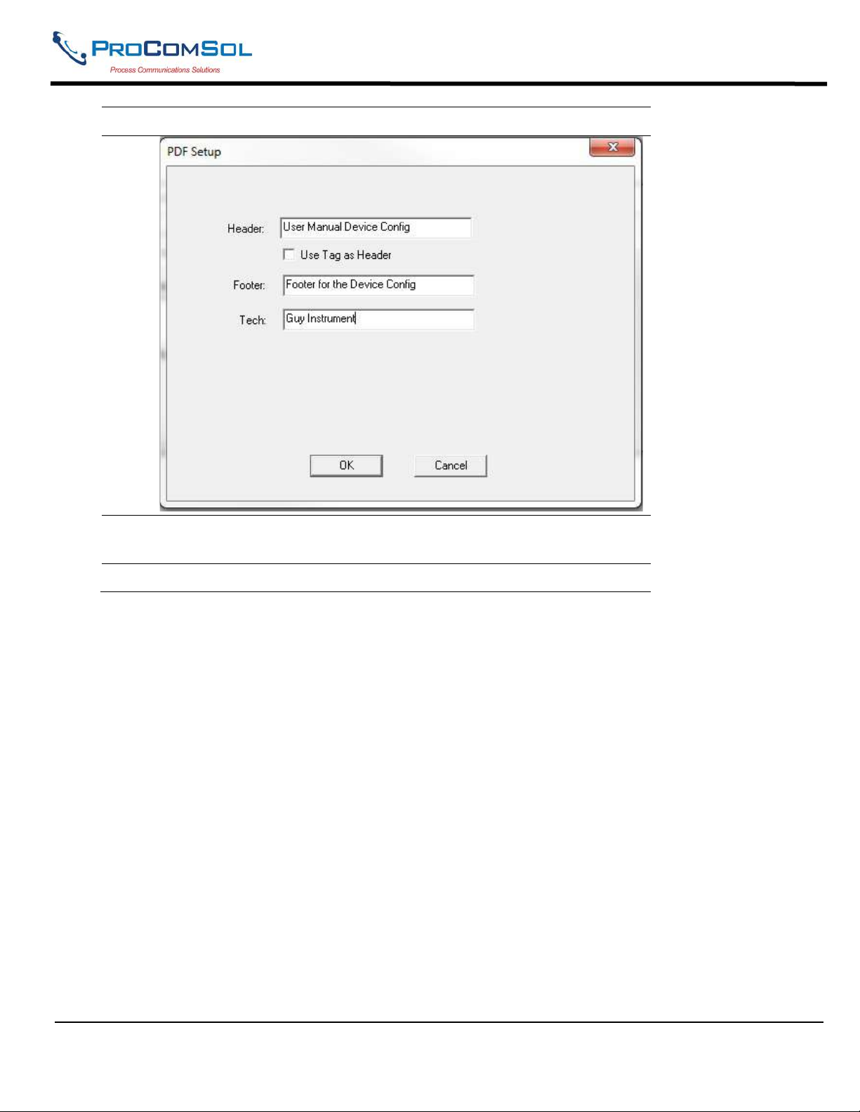
The HART Device configuration PDF file can be customized. A header, footer, and technician name can be
stored and used for each saved configuration. This is useful for contractors. The customer information can be
added to the PDF files to make a nice looking report.
To customize the PDF output, perform the following steps:
Step Action
1 Press the “PDF Setup” button on Document Device Dialog Box:
2 The PDF Setup Dialog box is displayed:
MAN-1010 10/21/2021 Providing Advanced Process Communication Page 39
Products Since 2005
Find Quality Products Online at: [email protected]
www.GlobalTestSupply.com
Page 40
DevCom2000 User Manual
Step Action
3 Enter data as needed and press OK. The data is saved for future
configuration saves.
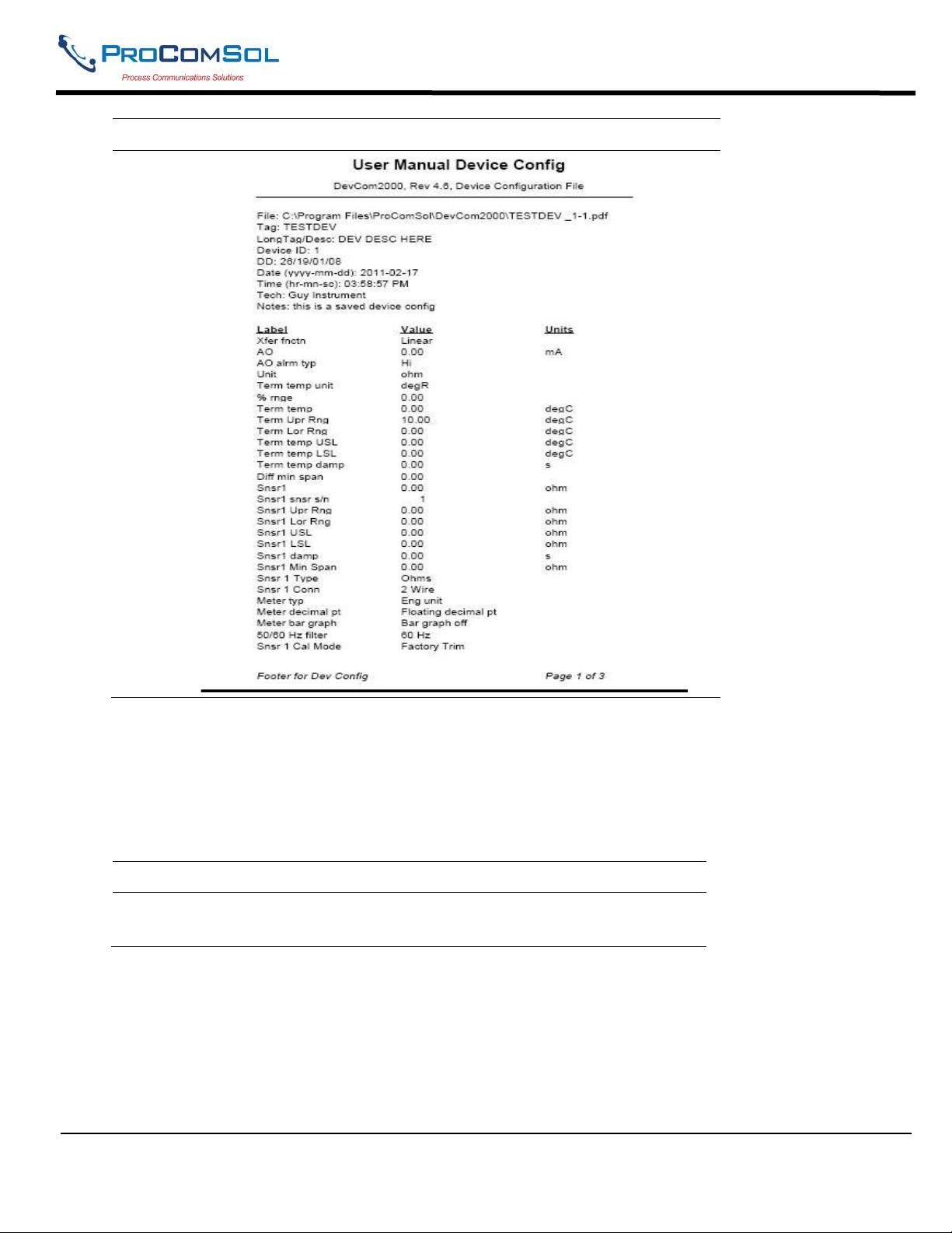
4 Below is a sample PDF file.
MAN-1010 10/21/2021 Providing Advanced Process Communication Page 40
Products Since 2005
Find Quality Products Online at: [email protected]
www.GlobalTestSupply.com
Page 41
DevCom2000 User Manual
Step Action
6.9 Download Configuration to Device
Saved configuration files can be downloaded back to devices. This is useful for “Cloning” a device, either for
replacement or plant setup.
To save device configurations to disk, perform the following steps:
Step Action
1 Ensure that the application is running and communications have been
established:
MAN-1010 10/21/2021 Providing Advanced Process Communication Page 41
Products Since 2005
Find Quality Products Online at: [email protected]
www.GlobalTestSupply.com
Page 42
DevCom2000 User Manual
Step Action
2 Select Device Download from the main window. The Download
Dialog Box is displayed:
Location is either:
Local - Stored on the hard drive of this computer
Cloud - Stored on the cloud
Local/Cloud - Stored at both locations
3 The available configurations are displayed. You can sort on each
column by clicking it.
MAN-1010 10/21/2021 Providing Advanced Process Communication Page 42
Products Since 2005
Find Quality Products Online at: [email protected]
www.GlobalTestSupply.com
Page 43

DevCom2000 User Manual
Step Action
To get details about a configuration, double click on the desired
configuration. The details will be displayed below.
4 You can change the desired Tag by editing the Configuration File
Tag box. You can change the desired Description by editing the
Config. File LongTag/Desc box.
5 Press the “Write” button to write device configuration to the device.
The device must be the same type as the configuration file. If they
are different, the write operation will be aborted.
6 You can view the PDF file for the configuration file by double
clicking on the desired configuration and clicking “View”.
7 You can delete configurations by double clicking on the desired
configuration and clicking “Delete”.
8 Click “Browse” to load a configuration stored in another directory or
on another location on your network.
9 Click Up/Down Load to copy the configuration from the cloud to the
local hard drive. Or to copy the configuration to the cloud from the
local hard drive. A Cloud subscription is required for this feature.
6.10 CalCheck (Calibration Check)
6.10.1 Saved Calibration Checks
The HART compatible field device must be connected to a PC or tablet running DevCom2000 to calibrate the
field device, or to view the field device's data. Make sure to establish the physical connection between the
field device and the DevCom2000 computer. With the physical connection established, launch DevCom2000
by clicking the DevCom2000 icon on your desktop. You can also start the application by going to your
computer's Start Menu and selecting Start Programs ProComSol DevCom2000.
Step Action
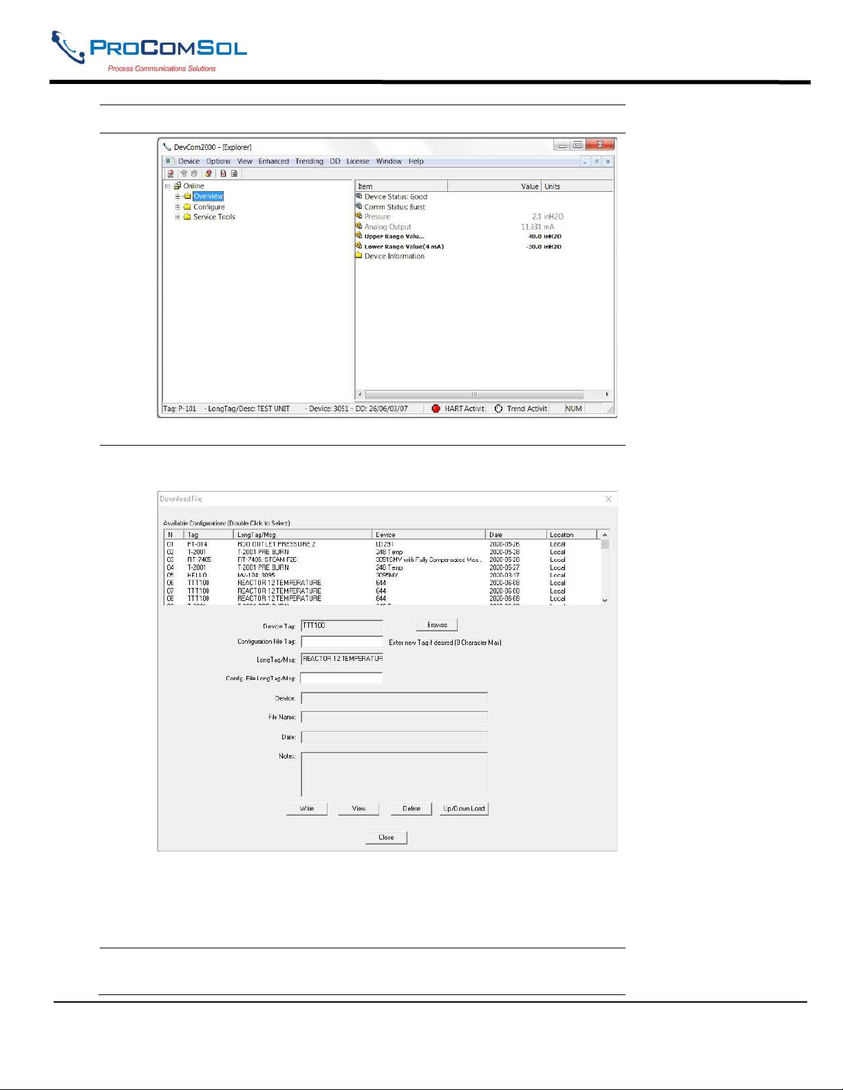
1 Start the DevCom2000 Application. The following application
window is displayed:
MAN-1010 10/21/2021 Providing Advanced Process Communication Page 43
Products Since 2005
Find Quality Products Online at: [email protected]
www.GlobalTestSupply.com
Page 44
DevCom2000 User Manual
DevCom2000 has automatically identified the field device, opened a
communication channel to (i.e., a connection with) the field device,
and loaded the proper DD.
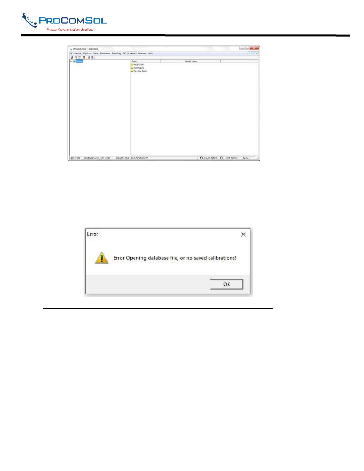
2 To start a CalCheck, click Device CalCheck on the top menu bar.
The first time CalCheck is run, an error message will appear. This is
normal and can be ignored:
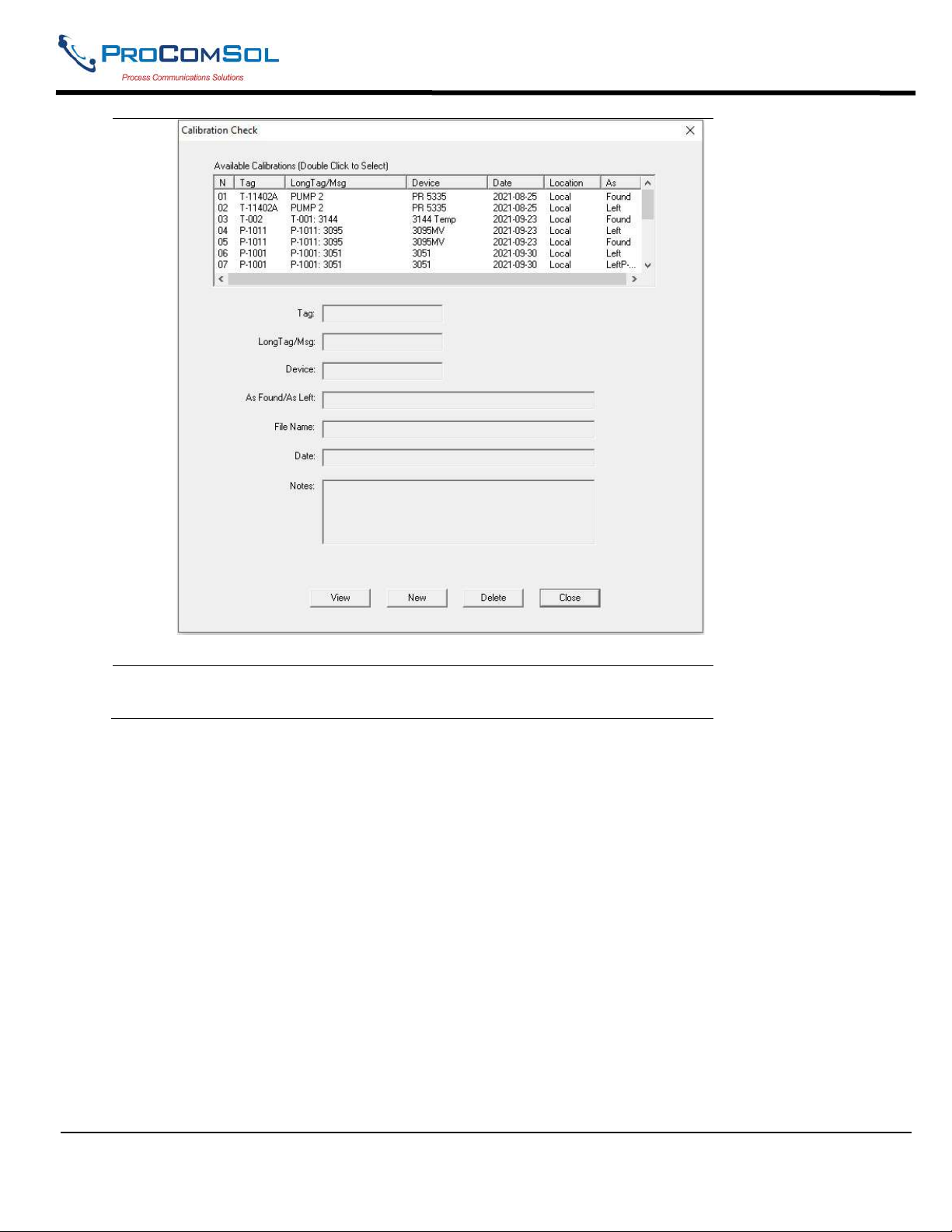
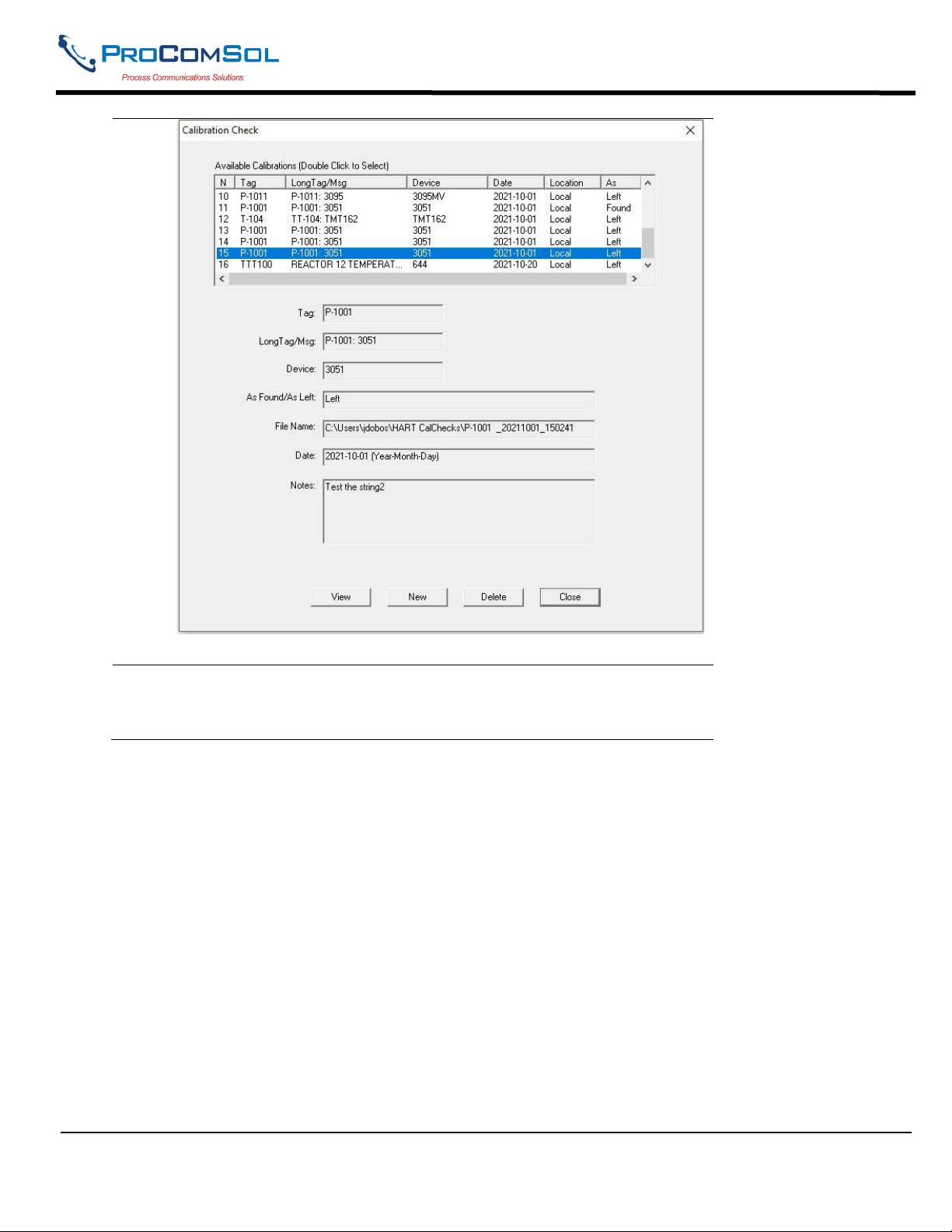
3 The Calibration Check dialog box now appears. It will show a list of
completed calibrations. Double click a calibration to view its details
in the edit boxes below.
MAN-1010 10/21/2021 Providing Advanced Process Communication Page 44
Products Since 2005
Find Quality Products Online at: [email protected]
www.GlobalTestSupply.com
Page 45
DevCom2000 User Manual
4 To get details about a calibration, double click on the desired
configuration. The details will be displayed below. For example:
MAN-1010 10/21/2021 Providing Advanced Process Communication Page 45
Products Since 2005
Find Quality Products Online at: [email protected]
www.GlobalTestSupply.com
Page 46
DevCom2000 User Manual
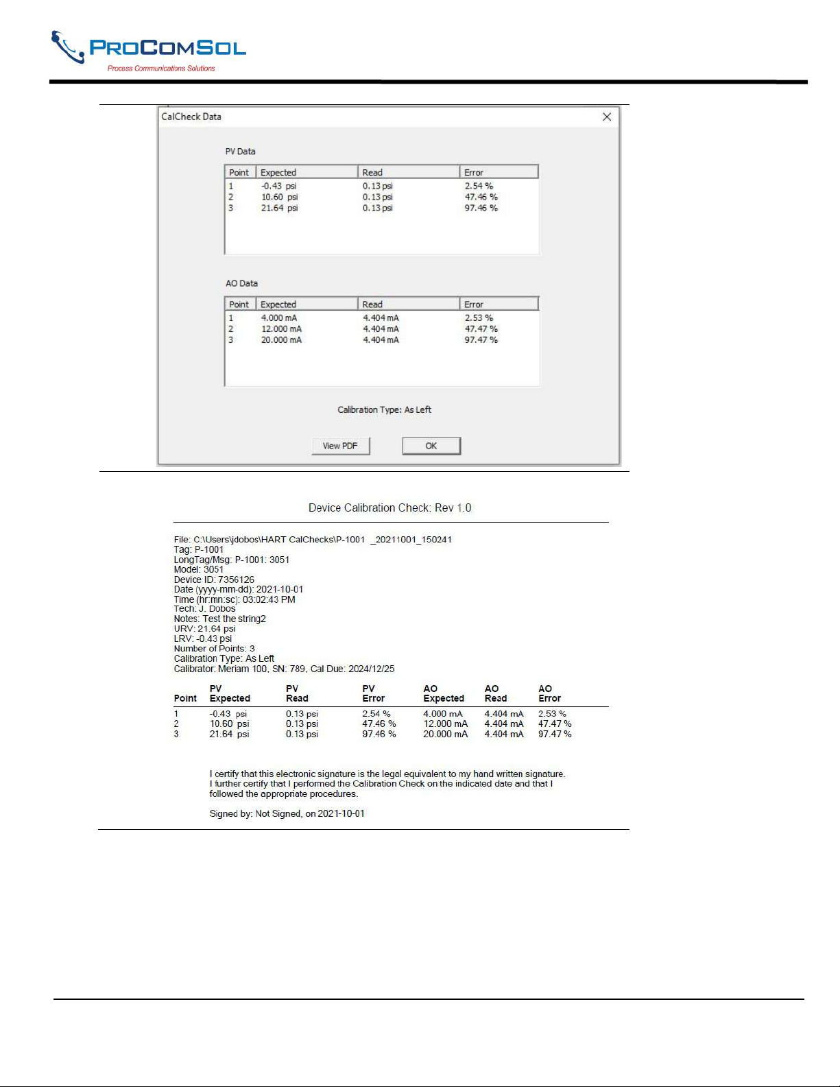
Click “View” to see the recorded data points.
5 The CalCheck Data screen shows the expected, read, and error
information for the PV and AO parameters. The error is full scale
error.
MAN-1010 10/21/2021 Providing Advanced Process Communication Page 46
Products Since 2005
Find Quality Products Online at: [email protected]
www.GlobalTestSupply.com
Page 47
DevCom2000 User Manual
6 Click “View PDF” to see the calibration report as a PDF file.
6.10.2 New Calibration Check
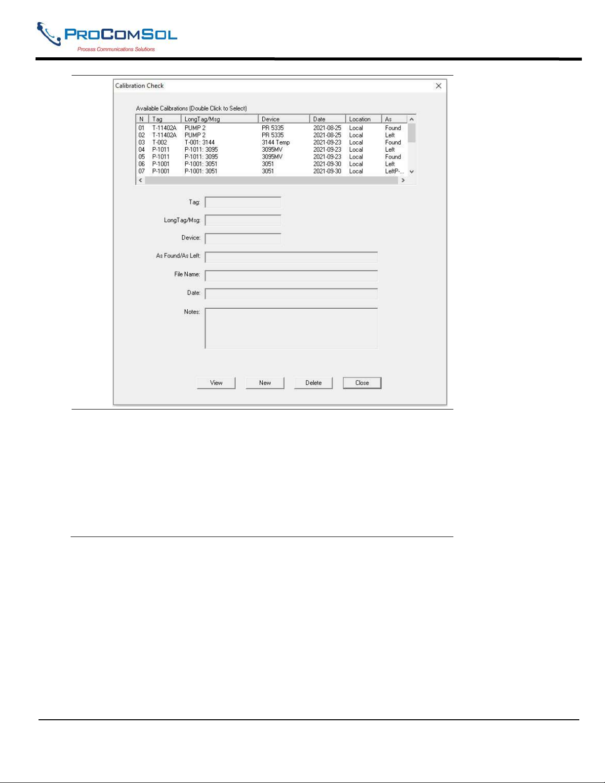
To create a new calibration, click New on the Calibration Check Screen.
MAN-1010 10/21/2021 Providing Advanced Process Communication Page 47
Products Since 2005
Find Quality Products Online at: [email protected]
www.GlobalTestSupply.com
Page 48
DevCom2000 User Manual
1
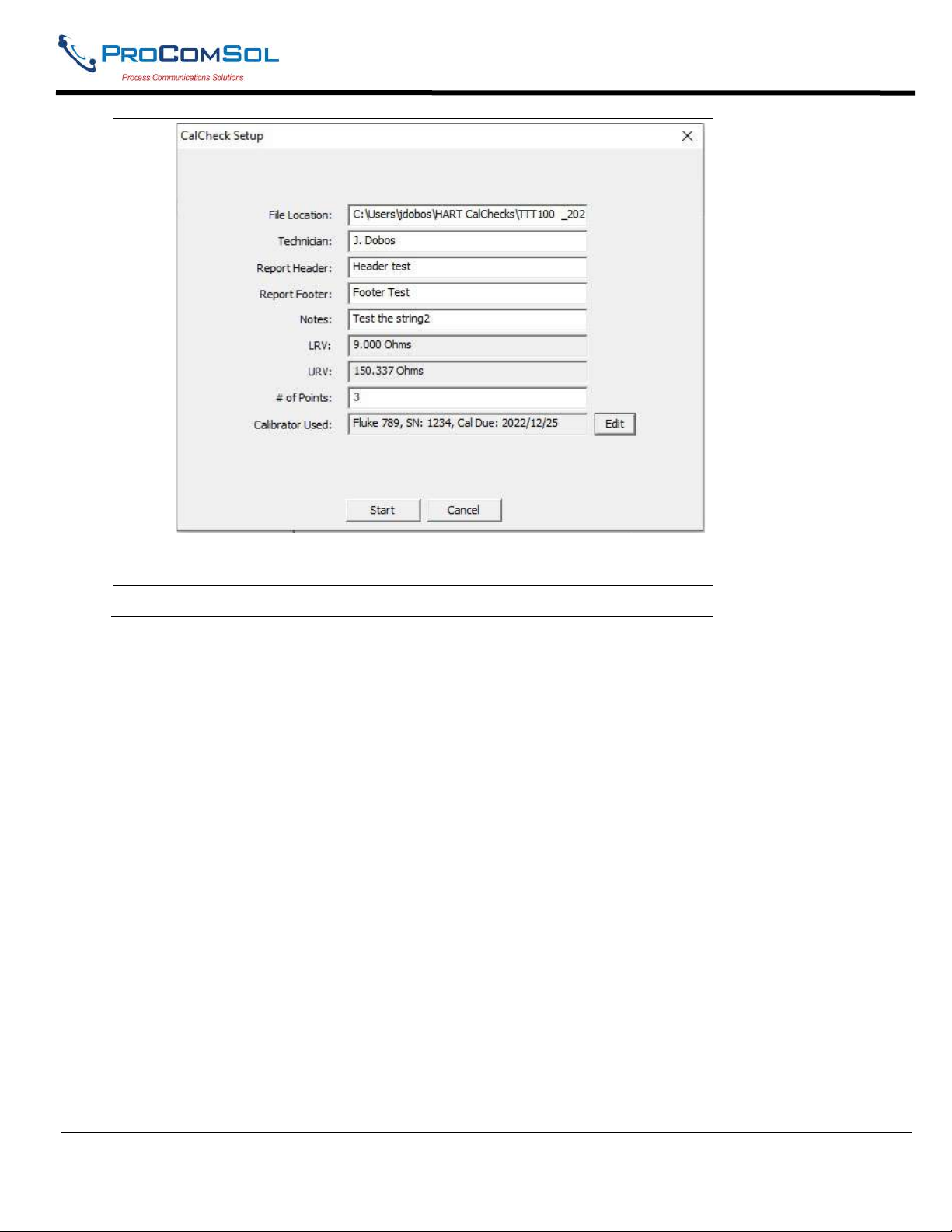
2 The Calibration Setup screen appears. Enter the data. The default file
name is the tag, followed by the date. You can edit this to whatever
you want.
The LRV and URV are read from the device and cannot be edited.
The # of Points is the number of points you want to check between the
LRV and the URV. The minimum is 2.
MAN-1010 10/21/2021 Providing Advanced Process Communication Page 48
Products Since 2005
Find Quality Products Online at: [email protected]
www.GlobalTestSupply.com
Page 49
DevCom2000 User Manual
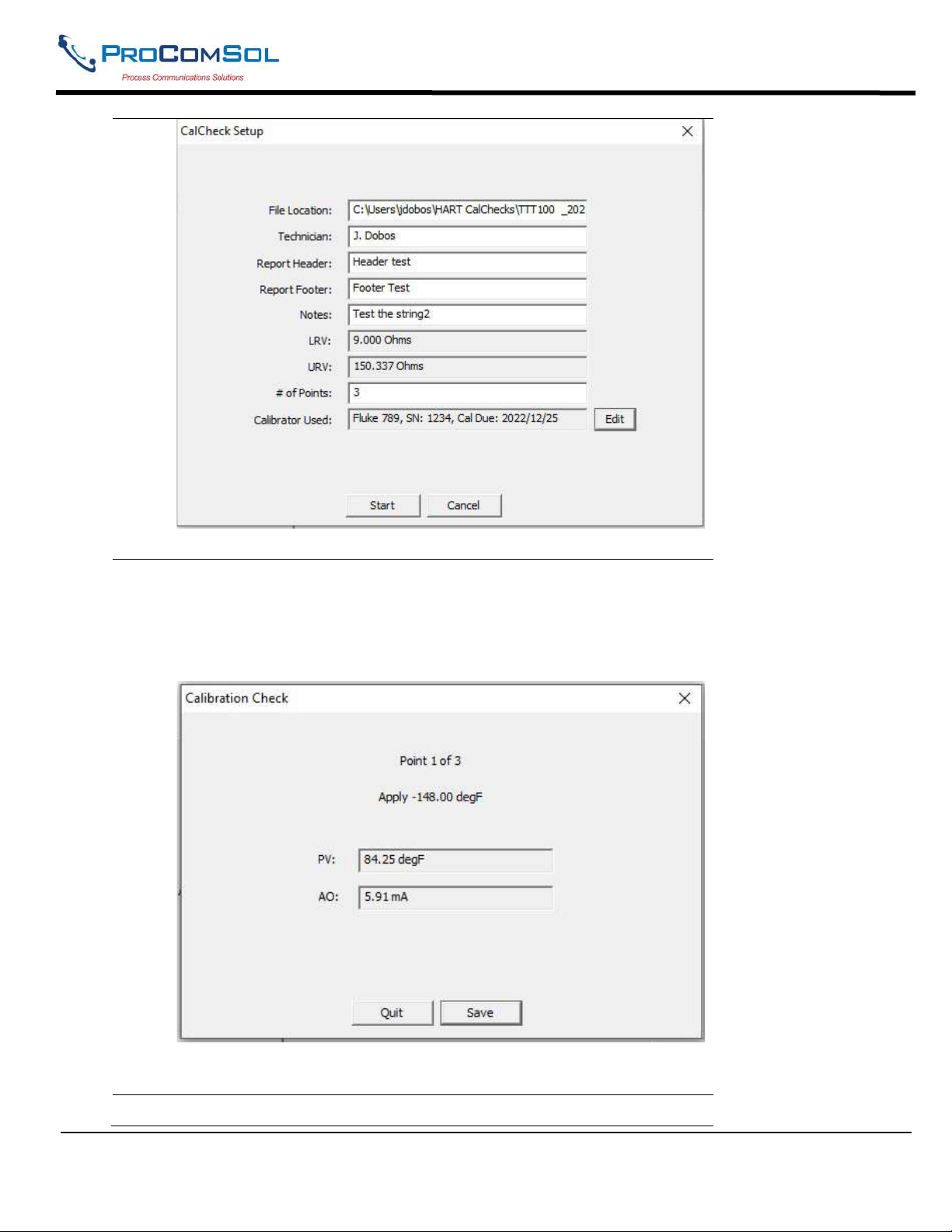
Once satisfied with your entries, click Start to begin.
3 The Calibration Check screen now appears for each calibration point.
It tells the user what value to the connected calibrator to. It also
shows the PV and AO values that DevCom2000 is reading from the
connected device via HART.
The user clicks “Save” to record these values and to move to the next
point. Click “Quit” to stop the calibration at any time.
4 After the last point is saved, the user is prompted to declare this
MAN-1010 10/21/2021 Providing Advanced Process Communication Page 49
Products Since 2005
Find Quality Products Online at: [email protected]
www.GlobalTestSupply.com
Page 50
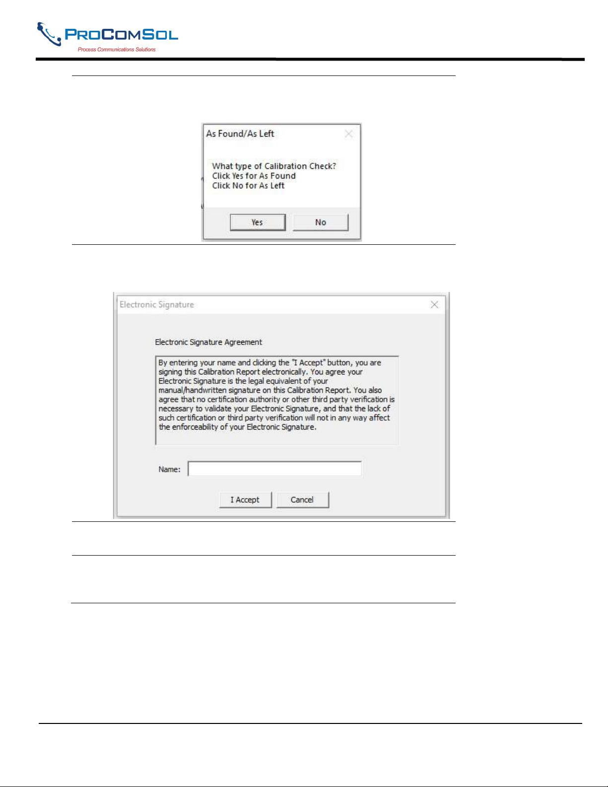
DevCom2000 User Manual
calibration to be either “As Found” or “As Left”. Click the
appropriate button.
5 The electronic Signature screen is then shown. Please read the
statement carefully, and if you agree, enter your name in the box and
click “I Accept”.
6 The calibration results screen is shown and the calibration report PDF
file is opened.
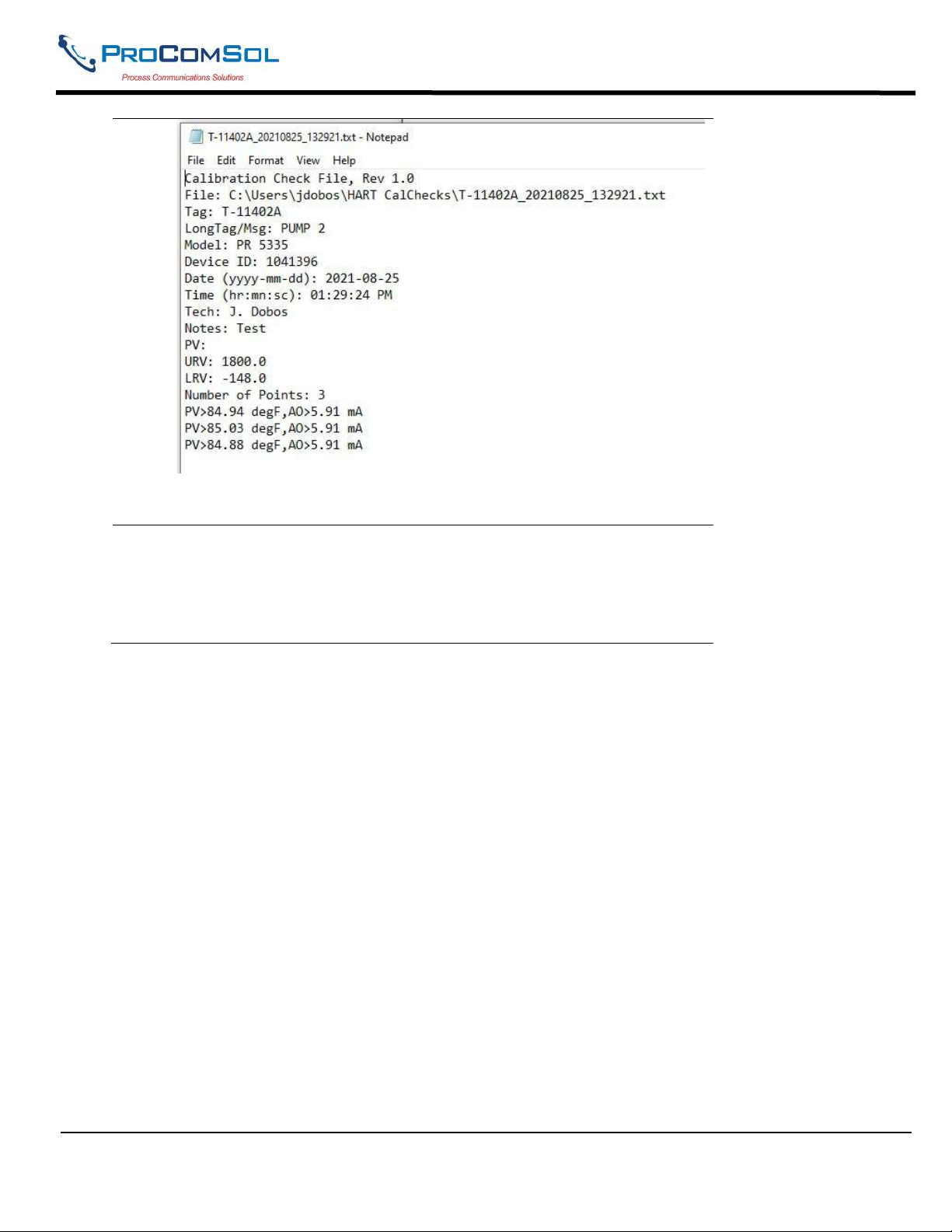
7 The CalCheck data is also saved as a text file. Use Windows File
Explorer to open the desired CalCheck file. The filename and
location are shown in Step 8 above.
MAN-1010 10/21/2021 Providing Advanced Process Communication Page 50
Products Since 2005
Find Quality Products Online at: [email protected]
www.GlobalTestSupply.com
Page 51
DevCom2000 User Manual
As you can see, the header information is stored along with the saved
points.
8 Based on the results of the CalCheck, the user can then perform Trim
operations with DevCom2000 using HART. Dismiss the CalCheck
screens and navigate through the device menus to find the appropriate
Trim Method for the connected device. Once trimmed, run CalCheck
again to verify the device is now operating within limits.
6.10.3 Calibrator Data Entry (Optional)
If you use several different calibrators in your shop, you can save the details of each one and associated it with
a CalCheck.
MAN-1010 10/21/2021 Providing Advanced Process Communication Page 51
Products Since 2005
Find Quality Products Online at: [email protected]
www.GlobalTestSupply.com
Page 52
DevCom2000 User Manual
1
Click “Edit” to Create, Edit and Select the Calibrator used in this
CalCheck.
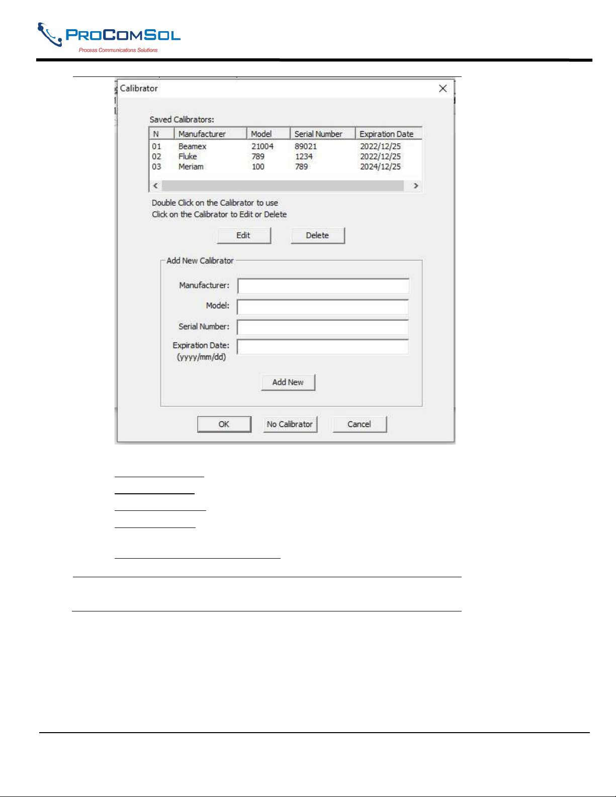
2 The Calibration dialog box shows the saved calibrators.
MAN-1010 10/21/2021 Providing Advanced Process Communication Page 52
Products Since 2005
Find Quality Products Online at: [email protected]
www.GlobalTestSupply.com
Page 53
DevCom2000 User Manual
From here you have several options:
Select a Calibrator - Double click on the Calibrator to use
Edit a Calibrator - Click to select, then click “Edit”.
Delete a Calibrator - Click to select, then click “Delete”.
Add a Calibrator - Enter the Calibrator information, then click “Add
New”.
Clear Calibrator for this CalCheck - Click “No Calibrator” to clear the
Calibrator field on the New Calibration dialog box.
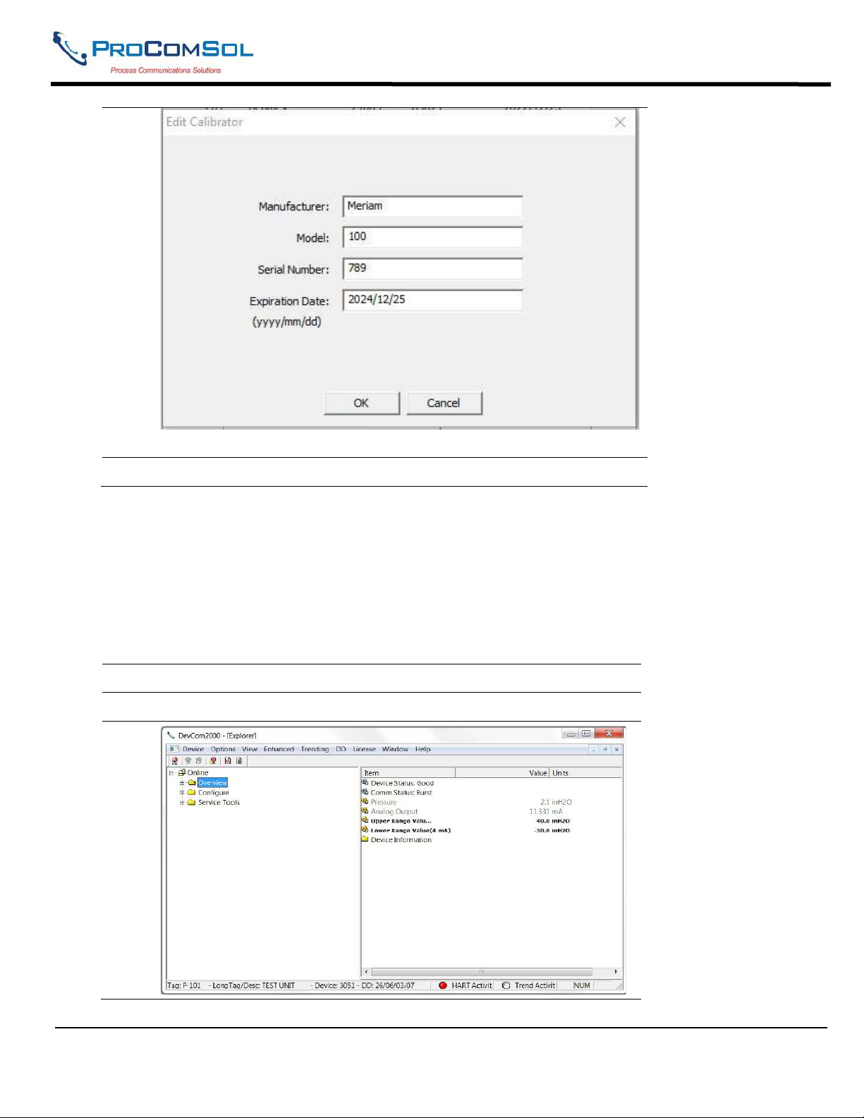
3 When “Edit” is clicked, the following Edit Calibrator dialog box is
opened:
MAN-1010 10/21/2021 Providing Advanced Process Communication Page 53
Products Since 2005
Find Quality Products Online at: [email protected]
www.GlobalTestSupply.com
Page 54
DevCom2000 User Manual
4 Make your edits and click “OK” when done.
6.11 Options Menu
6.11.1 Options Basic
6.12.1.1 Changing the COM port
The Basic menu is used to set the COM port to the correct one that the device is connected to. To change the
COM port, perform the following steps:
Step Action
1 Ensure that the application is running.
MAN-1010 10/21/2021 Providing Advanced Process Communication Page 54
Products Since 2005
Find Quality Products Online at: [email protected]
www.GlobalTestSupply.com
Page 55
DevCom2000 User Manual
Step Action
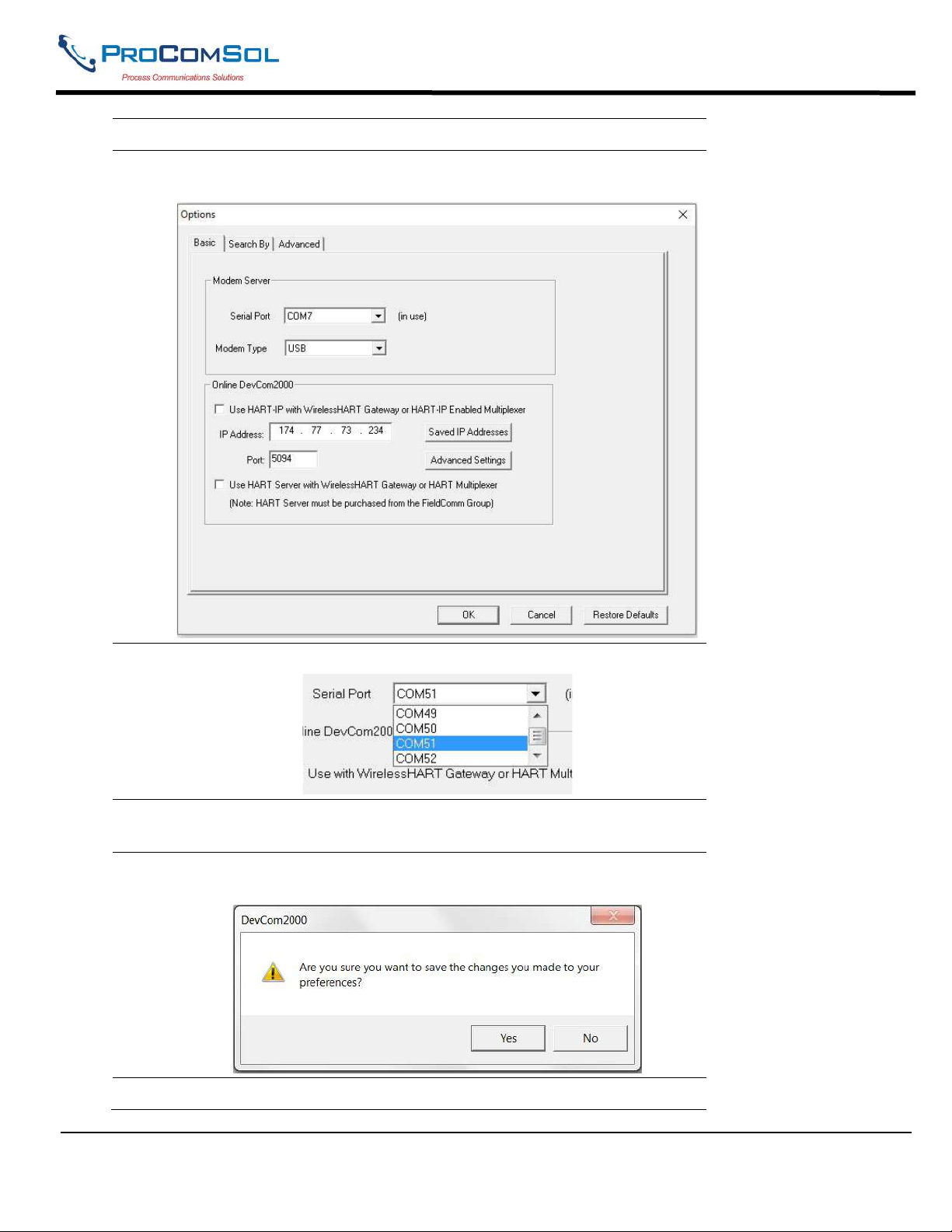
2 Select Options Basic from the main window. The Options Dialog
Box is displayed with the Basic tab selected:
3 To change serial ports, Click on the drop down box:
4 Once the desired COM port is selected click OK to save the changed
settings.
5 Click Yes if you want to save the changes. Clicking No will not save
the changes.
6 Select New Device from the Main screen to connect using the new
MAN-1010 10/21/2021 Providing Advanced Process Communication Page 55
Products Since 2005
Find Quality Products Online at: [email protected]
www.GlobalTestSupply.com
Page 56
DevCom2000 User Manual
Step Action
COM port.
6.12.1.2 Use HART-IP with a WirelessHART Gateway or HART-IP Multiplexer
The Basic menu is where DevCom2000 can be set to use HART-IP to communicate with a WirelessHART
Gateway or HART-IP enabled Multiplexer/Gateway. To communicate using HART-IP with
WirelessHART Gateway, perform the following steps:
Step Action
1 Ensure that the application is running.
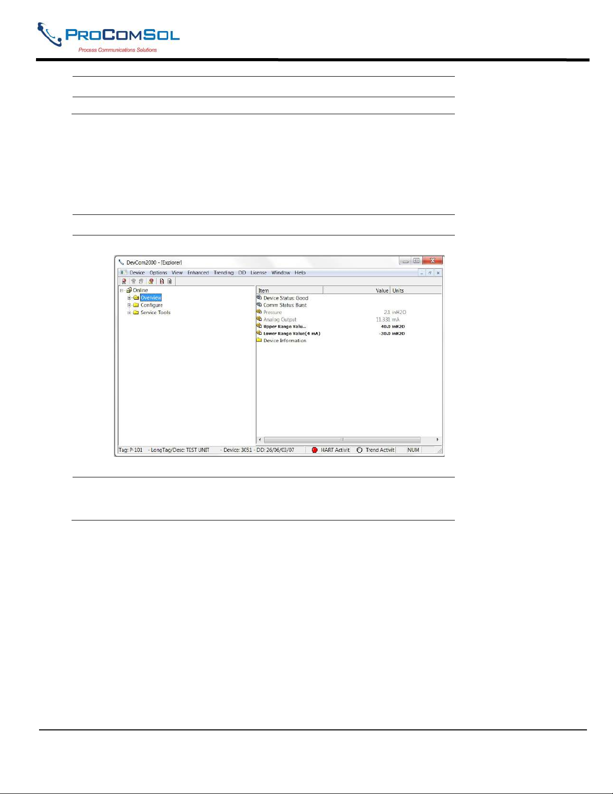
2
Select Options Basic from the main window. The Options Dialog
Box is displayed with the Basic tab selected:
MAN-1010 10/21/2021 Providing Advanced Process Communication Page 56
Products Since 2005
Find Quality Products Online at: [email protected]
www.GlobalTestSupply.com
Page 57
DevCom2000 User Manual
Step Action
3
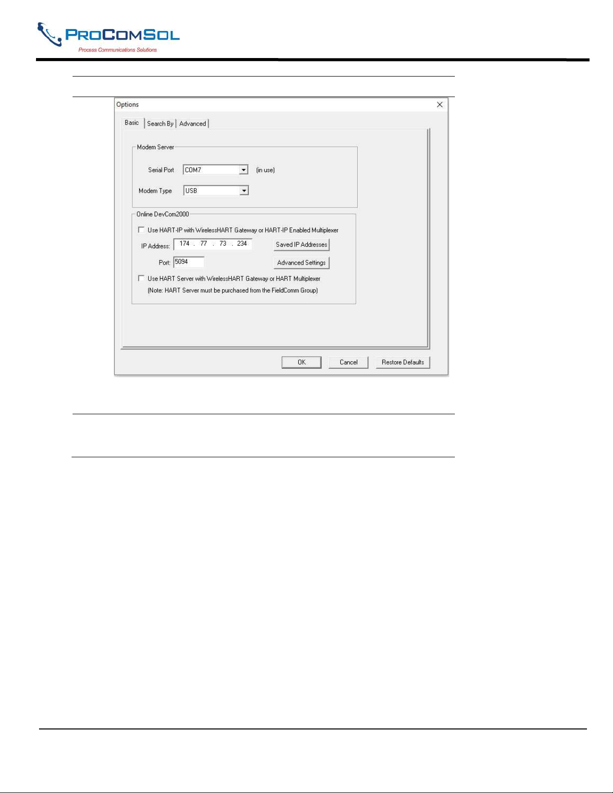
Click “Use HART-IP with WirelessHART Gateway or HART-IP
enabled Multiplexer”
MAN-1010 10/21/2021 Providing Advanced Process Communication Page 57
Products Since 2005
Find Quality Products Online at: [email protected]
www.GlobalTestSupply.com
Page 58
DevCom2000 User Manual
Step Action
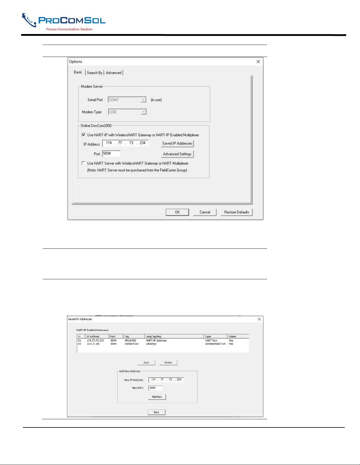
4
5
The Serial Port and Modem Type options will now be grayed out.
Un-checking will make Serial Port and Modem Type selectable
again.
Enter the IP Address of the HART-IP Gateway in the IP Address
Field. Also enter the Port assigned to HART-IP in the Gateway. It is
typically 5094.
Multiple IP Addresses can be saved to make connecting to different
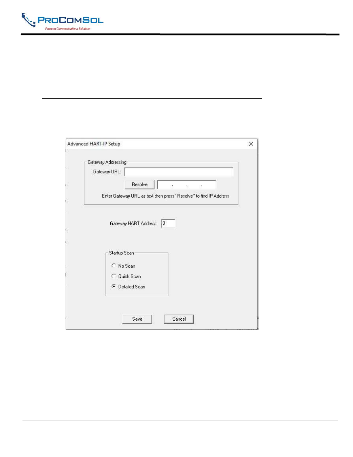
networks easier. Click Saved IP Addresses to configure and select
additional IP Addressess. When clicked the following dialog box
appears:
MAN-1010 10/21/2021 Providing Advanced Process Communication Page 58
Products Since 2005
Find Quality Products Online at: [email protected]
www.GlobalTestSupply.com
Page 59
DevCom2000 User Manual
Step Action
6
7
8
9
The saved IP Addresses are listed. From here you can Scan the
network using the selected IP Address. This will update the tag
details to the IP Address entry.
Delete will remove the IP Address from the list.
Add New will add the entered IP Address information to the list.
Click Scan to get tag details for the added IP Address.
For more advanced settings related to HART-IP, click the
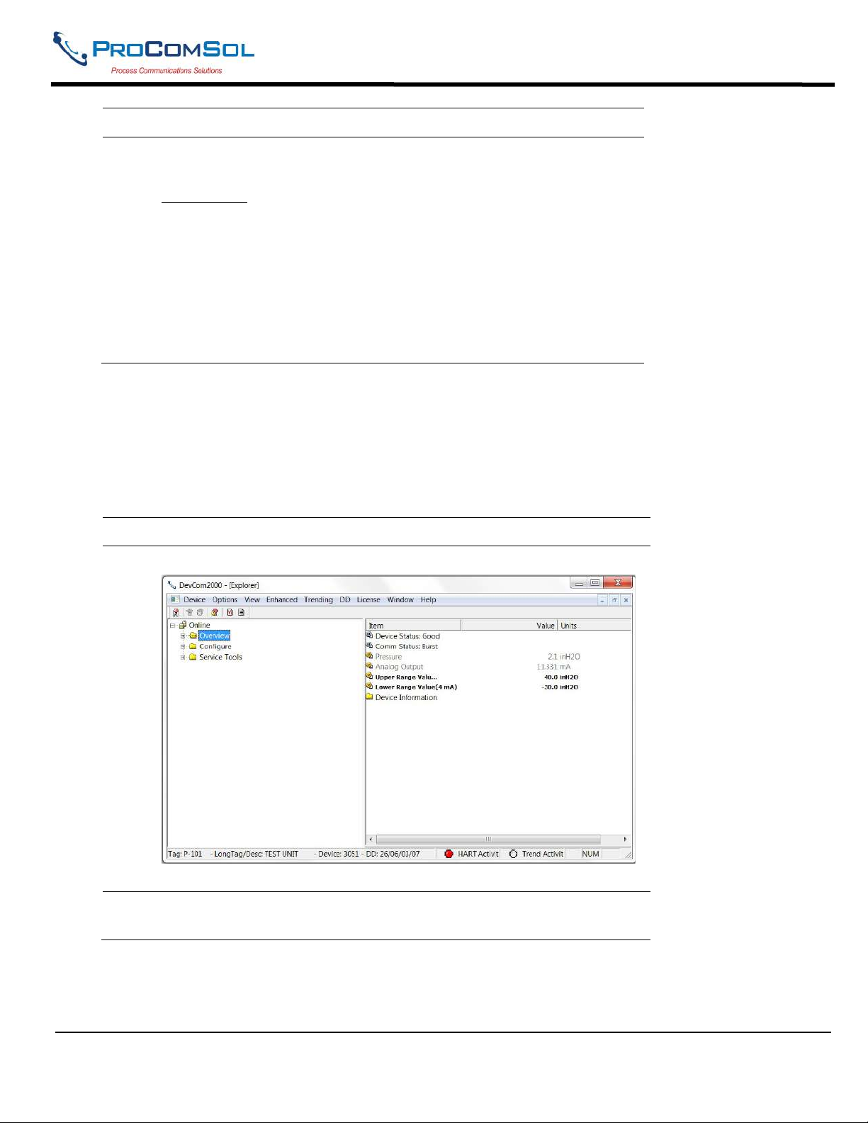
“Advanced” button. The following dialog box appears:
Communicating to a HART-IP Gateway via its URL
Enter a URL text address in the URL field and click the “Resolve”
button to convert it into an IP Address. The IP Address will populate
the IP Address box if a successful conversion occurs.
Gateway Address
Some WirelessHART Gateways do not use the default address of 0.
For these Gateways you must enter the correct Gateway Address in
MAN-1010 10/21/2021 Providing Advanced Process Communication Page 59
Products Since 2005
Find Quality Products Online at: [email protected]
www.GlobalTestSupply.com
Page 60
DevCom2000 User Manual
Step Action
this field.
Startup Scan
Select the desired scan to occur when DevCom2000 launches.
No Scan - No scan occurs
Quick Scan - All devices are listed without a heirachery.
Detailed Scan - This scan takes typically takes longer. All devices
are shown in a heirachrey. For instance, a wirelessHART adapter
with several sub devices is shown as the root device and the sub
devices are shown below it.
6.12.1.3 Using HART Server
HART Server is a program offered by the FieldComm Group to handle HART communications. It can be
used for a single device connected by a modem or for multiple devices connected to a wirelessHART
gateway or multiplexer. Note that it does not use HART-IP. To communicate with a WirelessHART
Gateway or a HART multiplexer without HART-IP, perform the following steps:
Step Action
1 Ensure that the application is running.
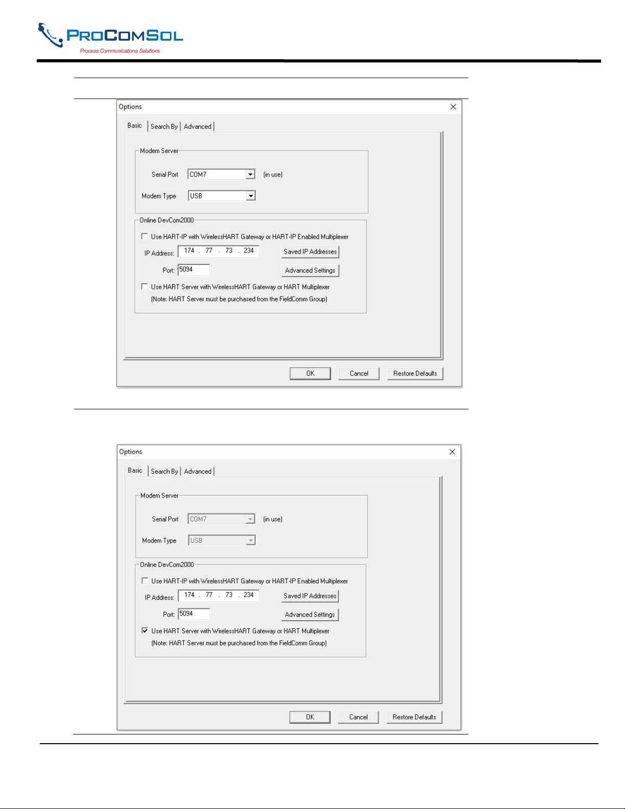
2 Select Options Basic from the main window. The Options Dialog
Box is displayed with the Basic tab selected:
MAN-1010 10/21/2021 Providing Advanced Process Communication Page 60
Products Since 2005
Find Quality Products Online at: [email protected]
www.GlobalTestSupply.com
Page 61
DevCom2000 User Manual
Step Action
3 Click “Use HART server with WirelessHART Gateway or HART
Multiplexer”
MAN-1010 10/21/2021 Providing Advanced Process Communication Page 61
Products Since 2005
Find Quality Products Online at: [email protected]
www.GlobalTestSupply.com
Page 62
DevCom2000 User Manual
Step Action
4 The Serial Port and Modem Type options will now be grayed out.
Un-checking will make Serial Port and Modem Type selectable again.
Click OK to save the changed settings.
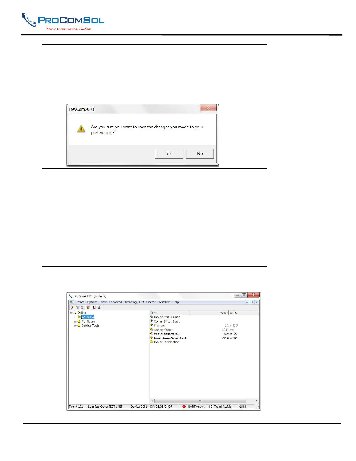
5 Click Yes if you want to save the changes. Clicking No will not save
the changes.
6 Restart DevCom2000 for the changes to take place.
6.11.3 Options Search
6.12.3.1 Poll Address
The Search menu is used to change how DevCom2000 searches for a Device. The first option is to search
by Poll Address. This searches for a specific poll address or set of addresses. To search for a device using
Poll Address perform these steps:
Step Action
1 Ensure that the application is running.
MAN-1010 10/21/2021 Providing Advanced Process Communication Page 62
Products Since 2005
Find Quality Products Online at: [email protected]
www.GlobalTestSupply.com
Page 63
DevCom2000 User Manual
Step Action
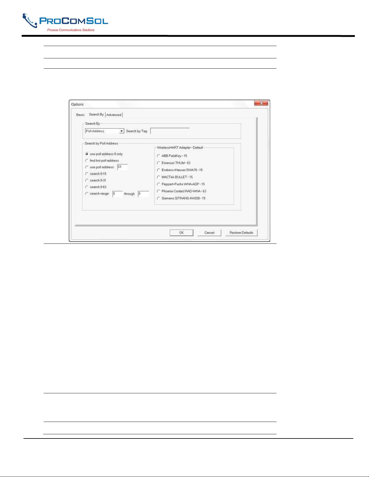
2 Select Options Search from the main window. The Options
Dialog Box is displayed with the Search By tab selected:
3 There are currently nine options for Poll address:
“Use poll address 0 only” only searches at poll address 0
before not finding a device. This is the default setting.
“Find first poll address” searches poll addresses until it finds
the first device it comes across.
“Use poll address: ___” If the poll address is know this options
searches at a specific address (i.e. 5).
“Search 0-15” searches poll addresses 0 through 15.
“Search 0-31” searches poll addresses 0 through 31.
“Search 0-63” searches poll addresses 0 through 63
“Search range ___ through ___” searches between a users’
identified range of poll addresses.
“MACTek Bullet – 15” searches poll address 15.
“Emerson Process Management THUM - 63” searches poll
address 63.
4 The Search by Tag option is grayed out when searching by poll
address. Select a search by poll address option and Click OK to save
the changed settings.
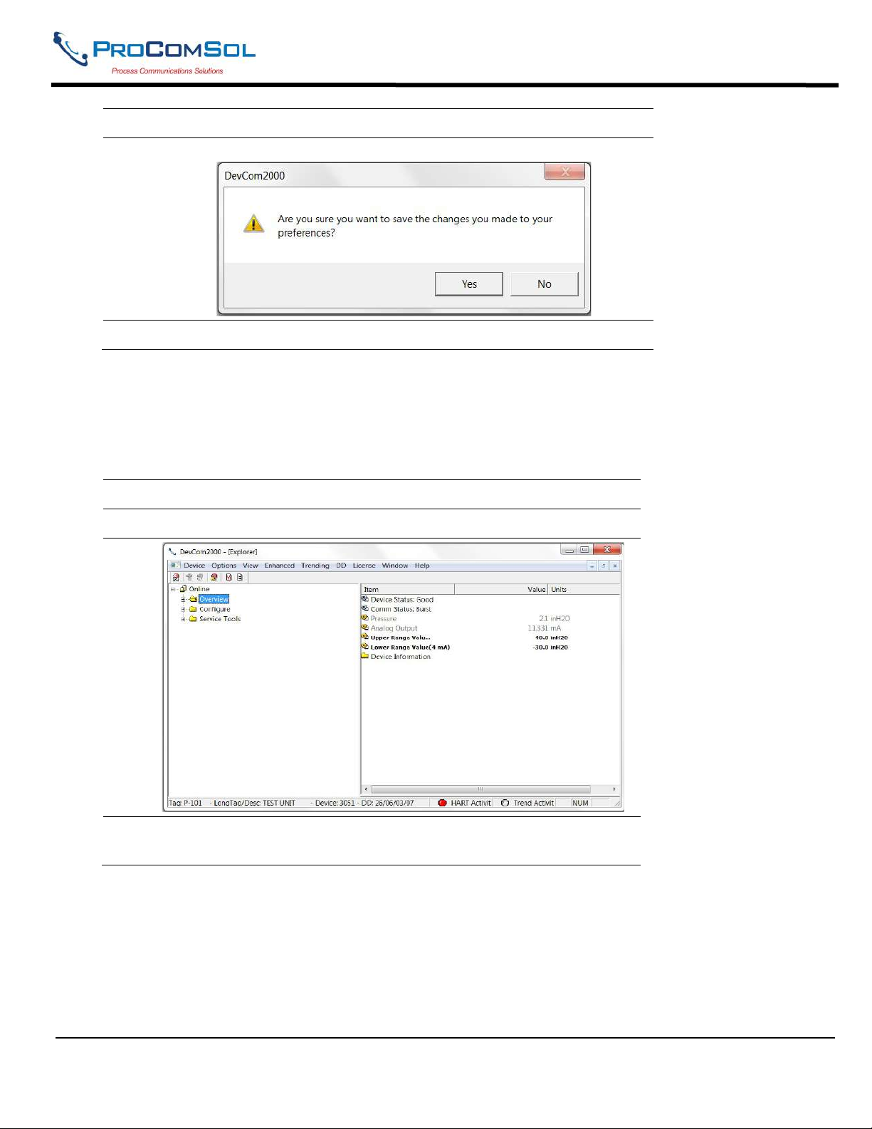
5 Click Yes if you want to save the changes. Clicking No will not save
MAN-1010 10/21/2021 Providing Advanced Process Communication Page 63
Products Since 2005
Find Quality Products Online at: [email protected]
www.GlobalTestSupply.com
Page 64
DevCom2000 User Manual
Step Action
the changes.
6 Reconnect to a new device.
6.12.3.2 Short Tag
The Search menu can also be used to search by a specific Tag name or Description. To search for a device
based on a Tag name or a Description, perform the following steps:
Step Action
1 Ensure that the application is running.
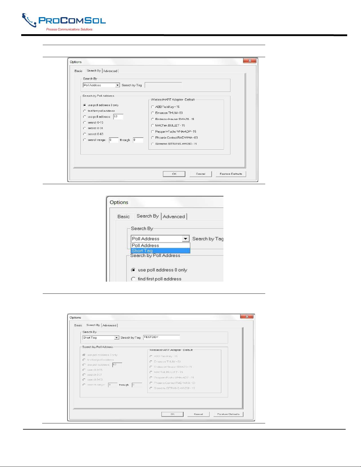
2 Select Options Search from the main window. The Options
Dialog Box is displayed with the Search By tab selected:
MAN-1010 10/21/2021 Providing Advanced Process Communication Page 64
Products Since 2005
Find Quality Products Online at: [email protected]
www.GlobalTestSupply.com
Page 65
DevCom2000 User Manual
Step Action
3 Select “Short Tag” from the Search By drop down box.
4 The poll address options will now be grayed out. Enter the tag to be
searched for in the “Search by Tag” edit box.
MAN-1010 10/21/2021 Providing Advanced Process Communication Page 65
Products Since 2005
Find Quality Products Online at: [email protected]
www.GlobalTestSupply.com
Page 66
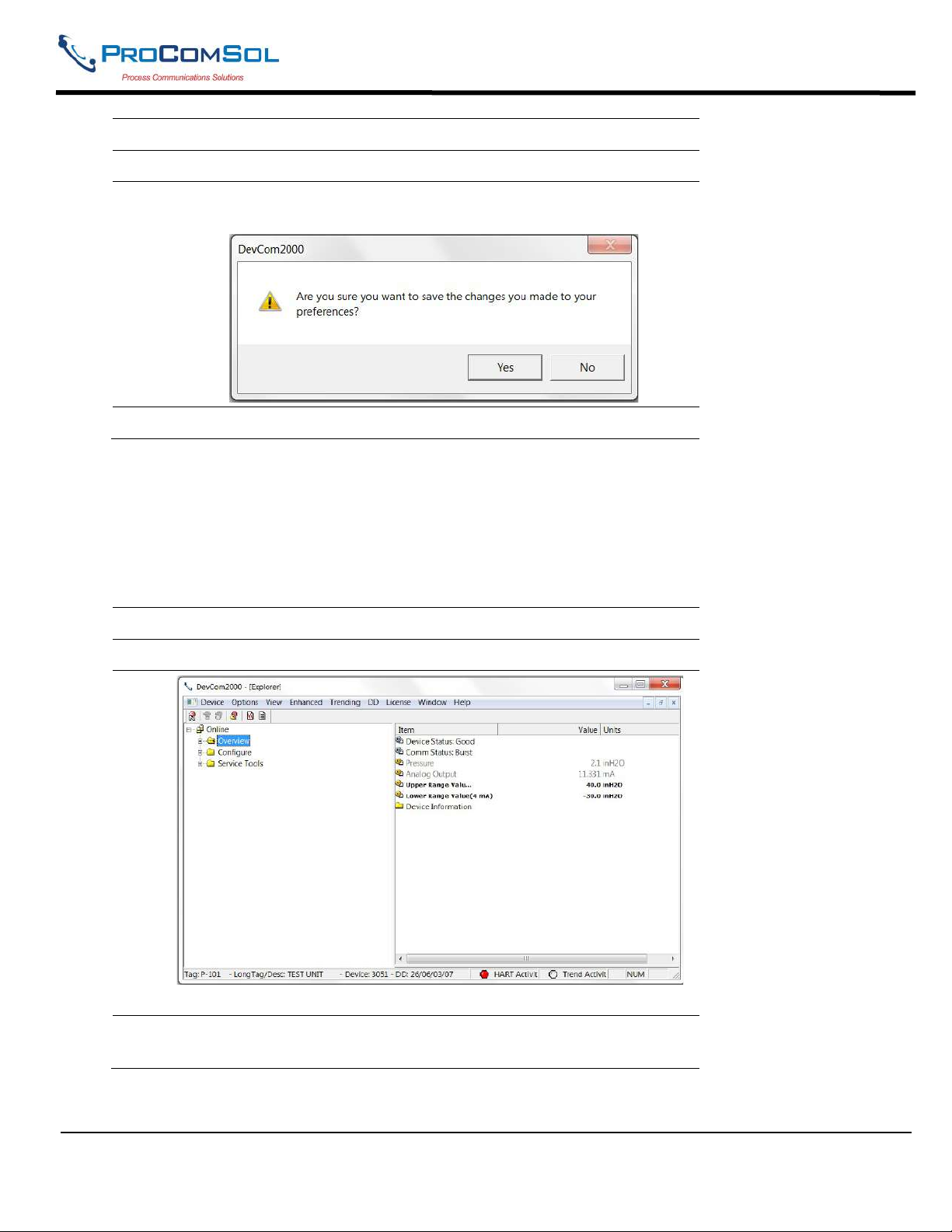
Step Action
5 Click OK to save the changed settings.
6 Click Yes if you want to save the changes. Clicking No will not save
the changes.
7 Reconnect to a new device.
6.11.4 Options Advanced
6.12.4.1 HART Master
DevCom2000 User Manual
The Advanced menu is used to change DevCom2000 settings. DevCom2000 can be a Primary or
Secondary HART Master. To change the HART Master setting, perform the following steps:
Step Action
1 Ensure that the application is running.
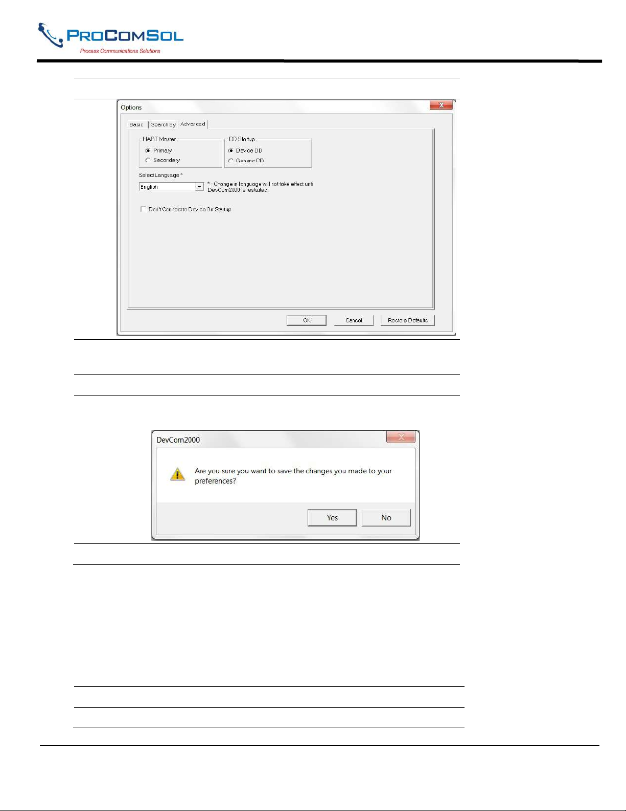
2 Select Options Advanced from the main window. The Options
Dialog Box is displayed with the Advanced tab selected:
MAN-1010 10/21/2021 Providing Advanced Process Communication Page 66
Products Since 2005
Find Quality Products Online at: [email protected]
www.GlobalTestSupply.com
Page 67
DevCom2000 User Manual
Step Action
3 Under the section “HART Master” select either “Primary” or
“Secondary”. Note that Secondary is the recommended setting.
4 Click OK to save the changed settings.
5 Click Yes if you want to save the changes. Clicking no will not save
the changes.
6 Restart DevCom2000 for the changes to take place.
6.12.4.2 Language
Certain DD’s can be used in different languages. English is the default setting but some support other
languages. Note that main program frame will always be English. Only the DD based items – menus,
variables, etc. will change language. And will only change if the DD supports that language. In order to
change the Language setting, perform the following steps:
Step Action
1 Ensure that the application is running.
MAN-1010 10/21/2021 Providing Advanced Process Communication Page 67
Products Since 2005
Find Quality Products Online at: [email protected]
www.GlobalTestSupply.com
Page 68
DevCom2000 User Manual
Step Action
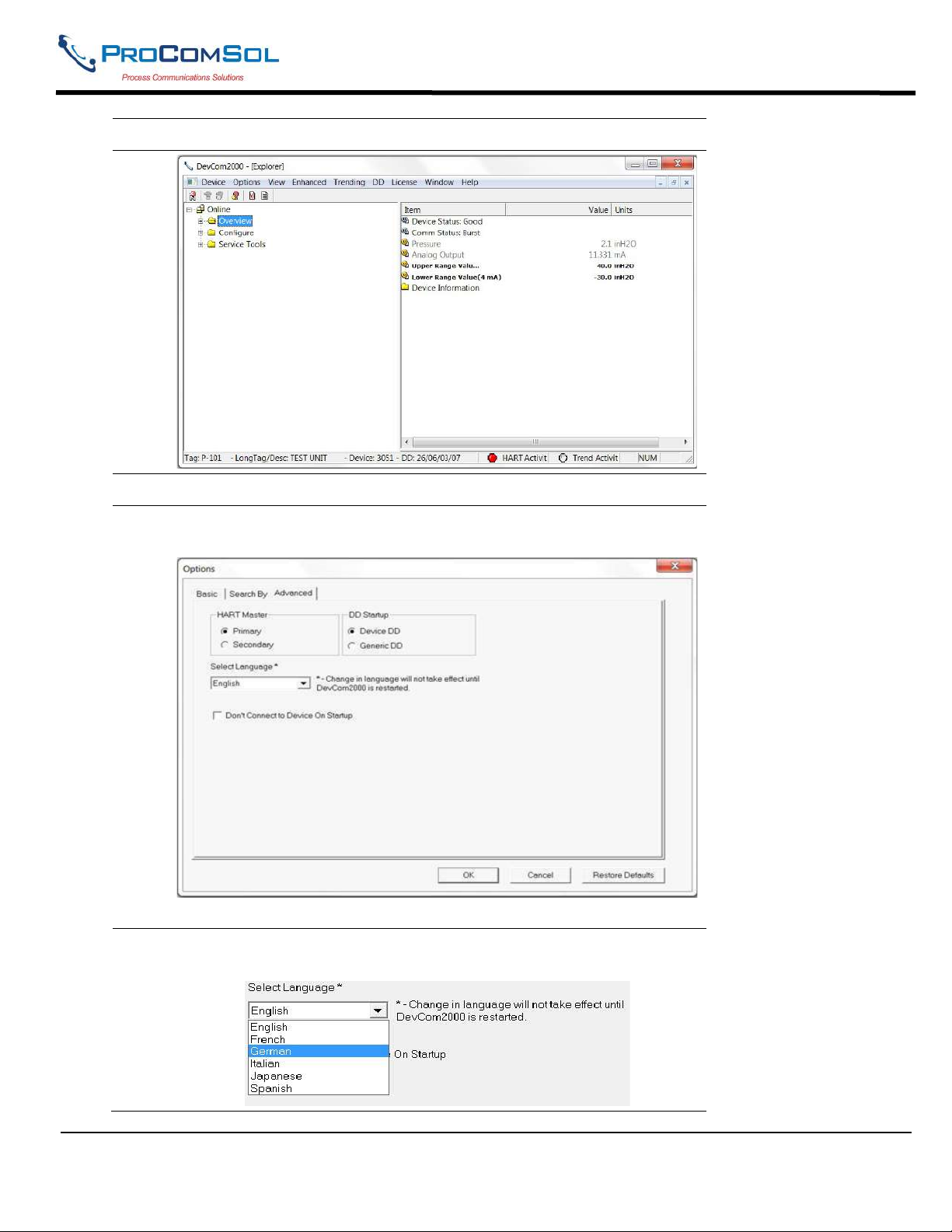
2 Select Options Advanced from the main window. The Options
Dialog Box is displayed with the Advanced tab selected:
3 Click the “Select Language” drop down to select a different
language.
MAN-1010 10/21/2021 Providing Advanced Process Communication Page 68
Products Since 2005
Find Quality Products Online at: [email protected]
www.GlobalTestSupply.com
Page 69
DevCom2000 User Manual
Step Action
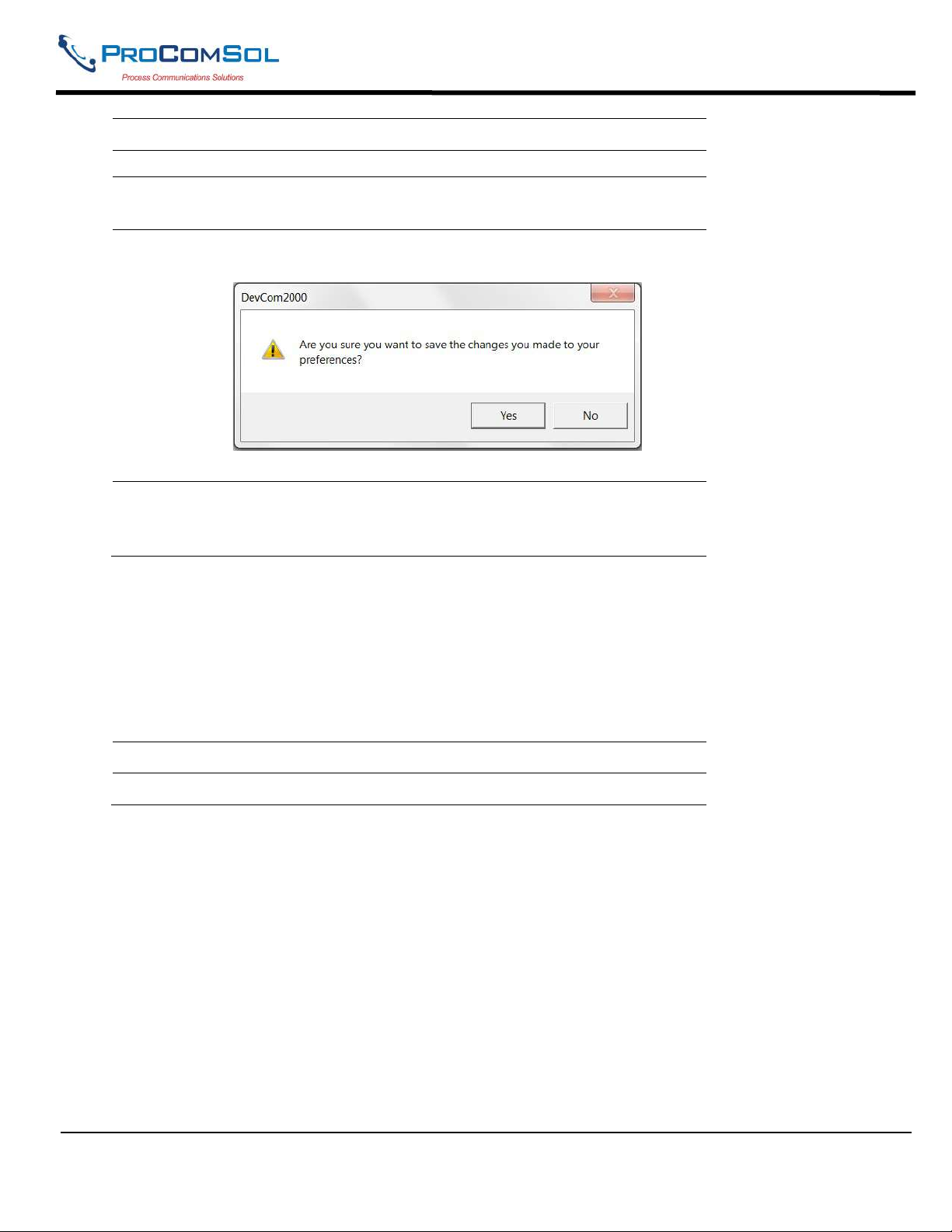
4 Select a language to translate the DD into. Click Okay to save the
changed settings.
5 Click Yes if you want to save the changes. Clicking no will not save
the changes.
6 Restart DevCom2000 for the changes to take place. If the language is
supported the DD will be translated. If not, the DD with default to
English.
6.12.4.3 DD Startup
During normal startup of DevCom2000, the device is found and then the DD is loaded. If the DD cannot be
found then a generic DD is loaded. Advanced has settings that can change what DD DevCom2000 loads
with loading a device. To load a generic DD at start up or to not load a DD at all perform the following
steps:
Step Action
1 Ensure that the application is running.
MAN-1010 10/21/2021 Providing Advanced Process Communication Page 69
Products Since 2005
Find Quality Products Online at: [email protected]
www.GlobalTestSupply.com
Page 70
DevCom2000 User Manual
Step Action
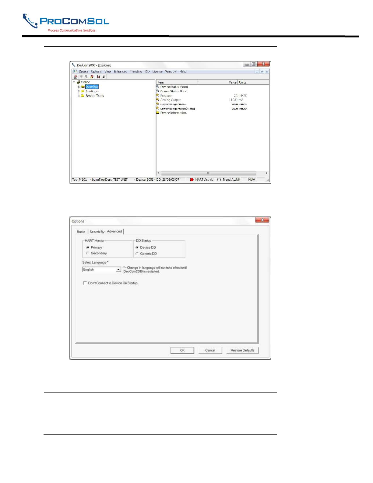
2 Select Options Advanced from the main window. The Options
Dialog Box is displayed with the Advanced tab selected:
3 Click either “Device DD” or “Generic DD” depending on which DD
is to be loaded when connecting to a device.
4 Check the “Don’t Connect to Device On Startup” to start
DevCom2000 without connecting to a device. Clicking “New
Device” will connect to a device after this start up.
5 Click OK to save the changed settings.
MAN-1010 10/21/2021 Providing Advanced Process Communication Page 70
Products Since 2005
Find Quality Products Online at: [email protected]
www.GlobalTestSupply.com
Page 71
DevCom2000 User Manual
Step Action
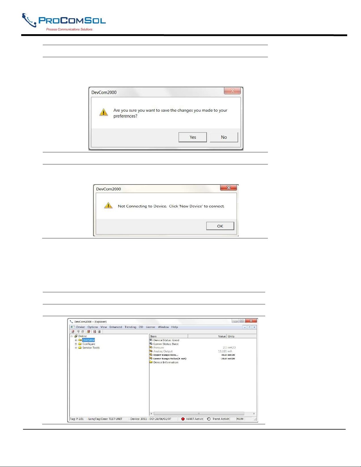
6 Click Yes if you want to save the changes. Clicking no will not save
the changes.
7 Restart DevCom2000 for the changes to take place.
8 If “Don’t Connect to Device On Startup” is checked the following
message will be displayed on start up:
6.12.4.4 Default Settings
The “Default” button on the Advanced tab Options resets all the advanced options to their default settings.
To return the settings to their default settings perform the following steps:
Step Action
1 Ensure that the application is running.
MAN-1010 10/21/2021 Providing Advanced Process Communication Page 71
Products Since 2005
Find Quality Products Online at: [email protected]
www.GlobalTestSupply.com
Page 72
DevCom2000 User Manual
Step Action
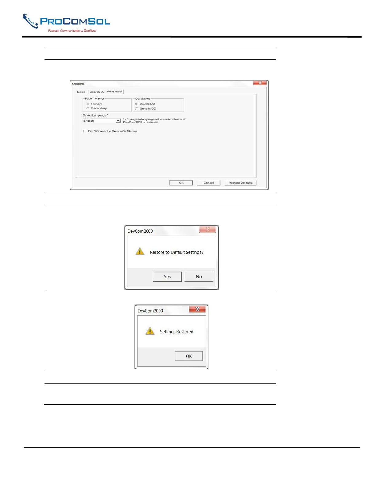
2 Select Options Advanced from the main window. The Options
Dialog Box is displayed with the Advanced tab selected:
3 Click the “Restore Defaults” button.
4 DevCom2000 will ask if you want to restore the default settings.
Click “Yes”
5 If the restore was successful the following dialog box will be shown:
6 Click OK to save the changed settings.
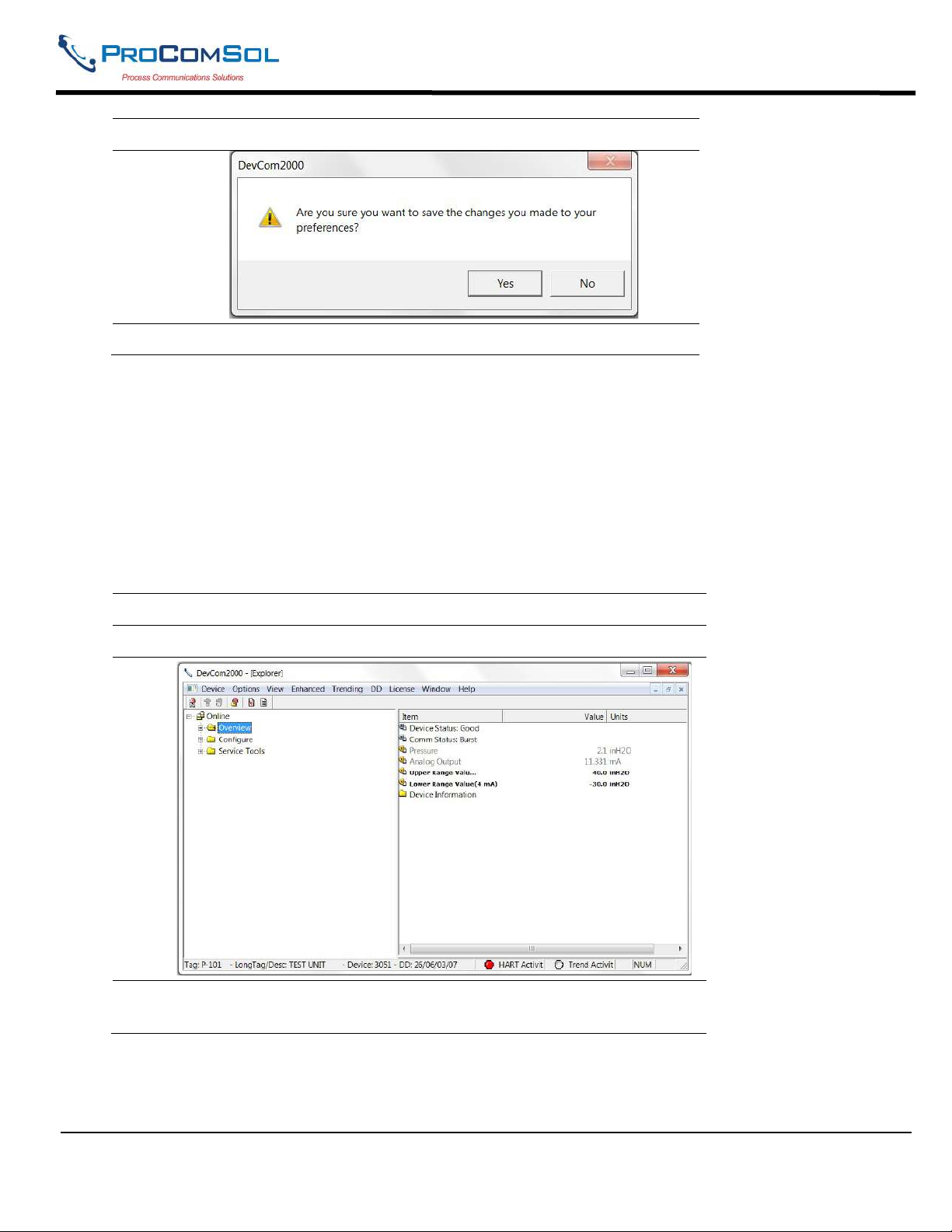
7 Click Yes if you want to save the changes. Clicking no will not save
the changes.
MAN-1010 10/21/2021 Providing Advanced Process Communication Page 72
Products Since 2005
Find Quality Products Online at: [email protected]
www.GlobalTestSupply.com
Page 73
DevCom2000 User Manual
Step Action
8 Restart DevCom2000 for the changes to take place.
6.12 Trending
6.12.1 Define Trend
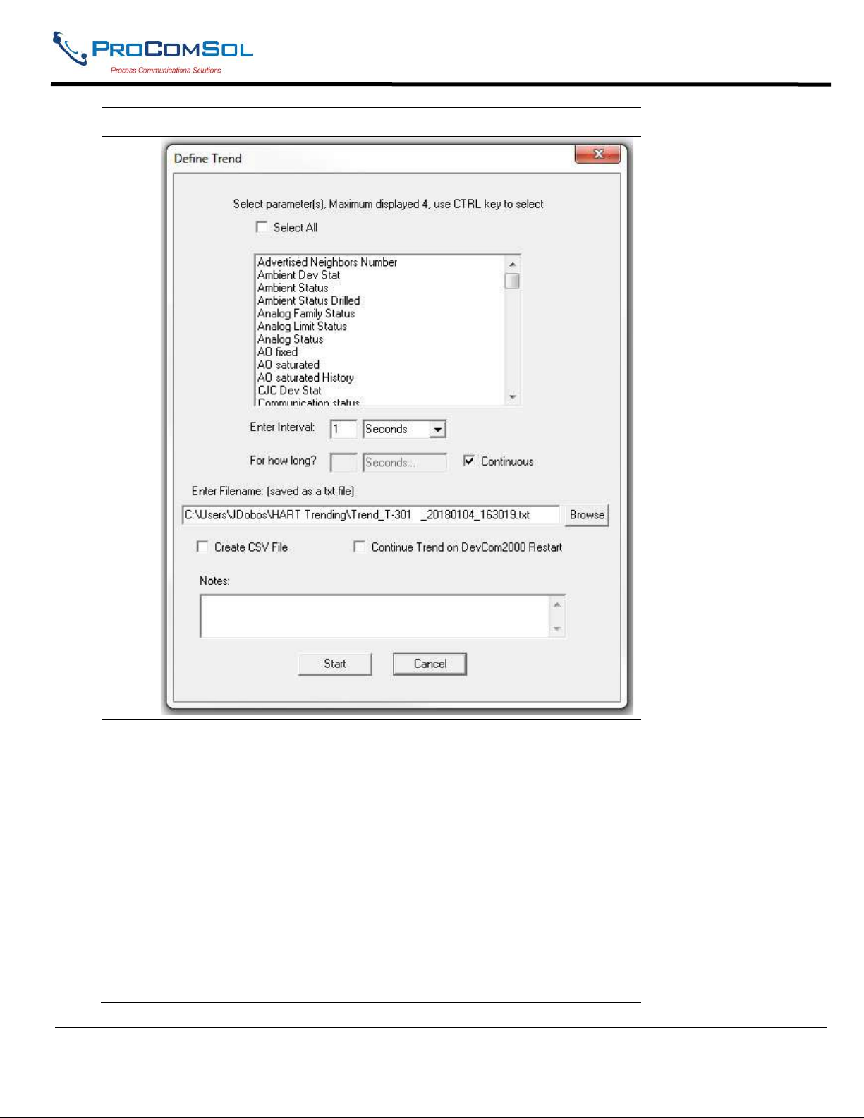
The Trending menu is used to track dynamic device parameters over a specified period of time. Once a
parameter is tracked, it can be graphed and compared against other parameters tracked on the same time
period. Before a parameter can be graphed, a trend must first be created. To create a trend, perform the
following steps:
Step Action
1 Ensure that the application is running and is connected to a device.
2 Select Trending Define Trend from the main window. The
Define Trend Dialog Box is displayed:
MAN-1010 10/21/2021 Providing Advanced Process Communication Page 73
Products Since 2005
Find Quality Products Online at: [email protected]
www.GlobalTestSupply.com
Page 74
DevCom2000 User Manual
Step Action
3 Select the information for the log file:
Select Parameters – Select up to four parameters to display at a
time. More than four can be recorded. Press the CNTRL key to
select multiple parameters.
Select All – All parameters are recorded, but only four are displayed.
Enter Interval - Input a number and select an interval from the drop
down box, i.e. Seconds, Minutes, Hours, and Days.
For How Long? – Input duration for how long to log the
parameter(s). This part will be grayed out if the “Continuous” check
box is selected. Unselect it for a finite duration.
Filename – The default directory is based on Windows User
Accounts however a log file can be saved anywhere.
Create CSV File – When selected a .csv file is also created for use in
MAN-1010 10/21/2021 Providing Advanced Process Communication Page 74
Products Since 2005
Find Quality Products Online at: [email protected]
www.GlobalTestSupply.com
Page 75
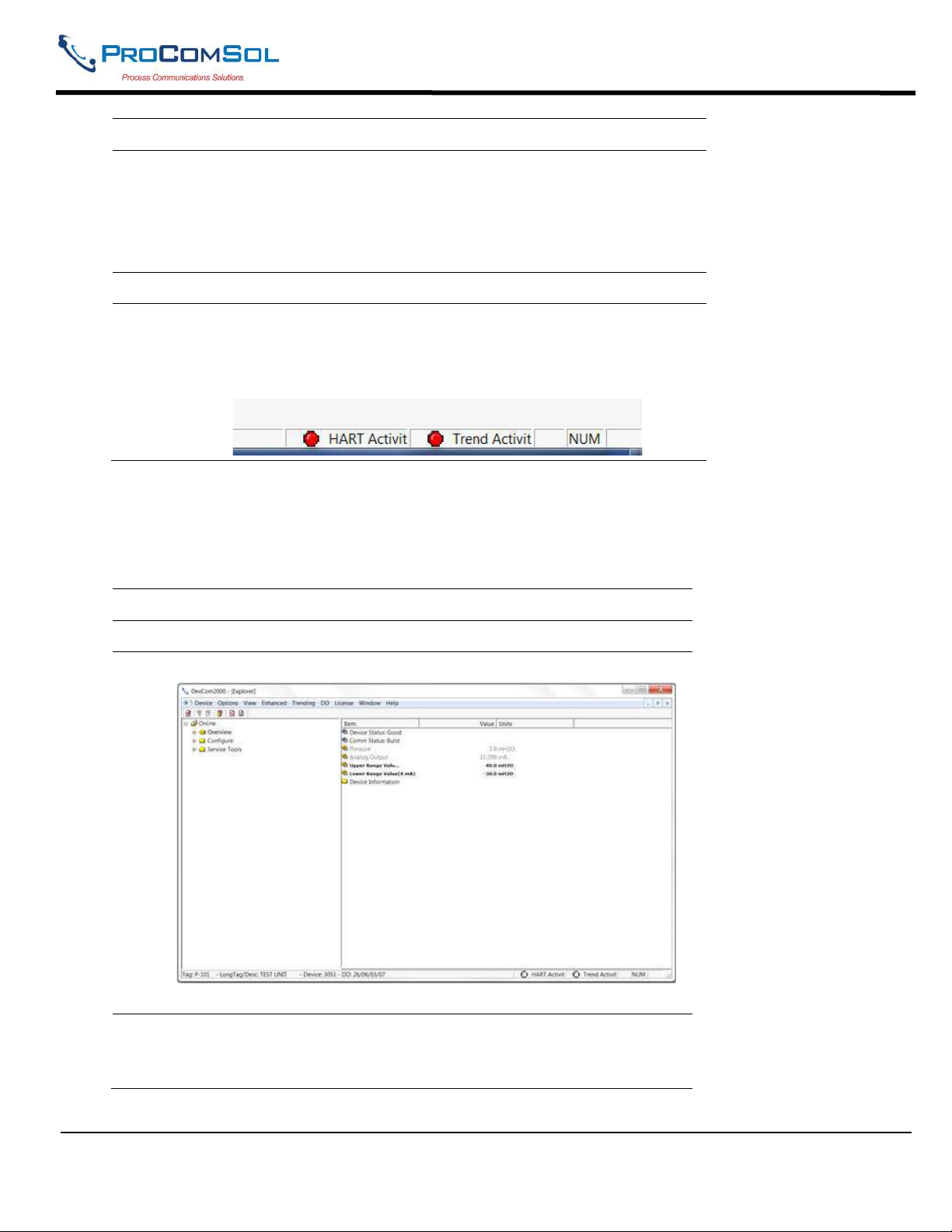
DevCom2000 User Manual
Step Action
3rd party software.
Continue Trend on DevCom2000 Restart – When selected, the
define trend is automatically restarted whenever DevCom2000 is
launched.
Notes – The section can only be 250 characters long.
4 Click the “Start” button to start logging.
5 The logging will then be started. At the lower right hand corner of
DevCom2000 the “Trend Activity” light will come on. This
indicates that there is logging going on. You cannot start another log
until this one is finished or the user stops the trend manually.
6.12.2 View Current Trend
When a trend is created DevCom2000 creates a window that shows the graph of the current trend. To view
this trend, perform the following steps:
Step Action
1 Ensure that the application is running and is connected to a device.
2 Ensure that a trend is in progress. The “Trend Activity” light at the
bottom of the screen is on if a trend is in progress. If not then the
light will be off.
MAN-1010 10/21/2021 Providing Advanced Process Communication Page 75
Products Since 2005
Find Quality Products Online at: [email protected]
www.GlobalTestSupply.com
Page 76
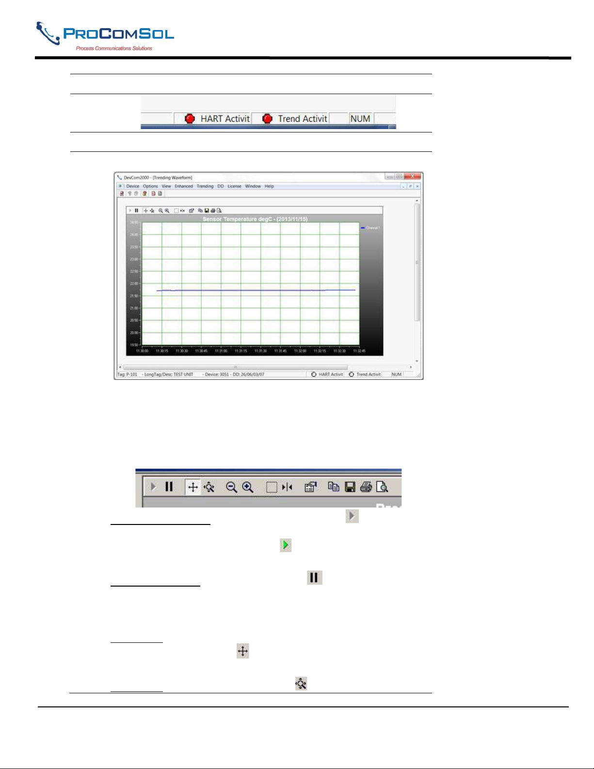
DevCom2000 User Manual
Step Action
3 Select Trending View Current Trend from the main window.
4 The DevCom2000 Trend dialog opens up.
The user can manipulate the graph as desired. “Tracking” is the
term used to describe how the graph control follows the data,
changing the axis in real time so that all of the data is shown.
Below are the specific parts of the graph:
Tool Bar: There are multiple things that the user can do with the
graph.
Resume All Tracking: The “Resume All” button - - is grayed
out while tracking. If either axis is changed or the “Pause” button
is pressed, this will be come green - - Pressing “Resume All
Tracking” will resume the tracking on the graph.
Pause All Tracking: The “Pause” button - - pauses the graph in
its current state. Data is still added, however the current X-axis and
Y-axis spans no longer change. Pressing the “Resume” button will
continue tracking.
Scroll Axis: This is the default way to scroll both the X and Y-axis.
The “Scroll Axis” button - - allows the user to scroll in both
directions on the graph.
Zoom Axis: The “Zoom Axis” button - - allows the user to
MAN-1010 10/21/2021 Providing Advanced Process Communication Page 76
Products Since 2005
Find Quality Products Online at: [email protected]
www.GlobalTestSupply.com
Page 77
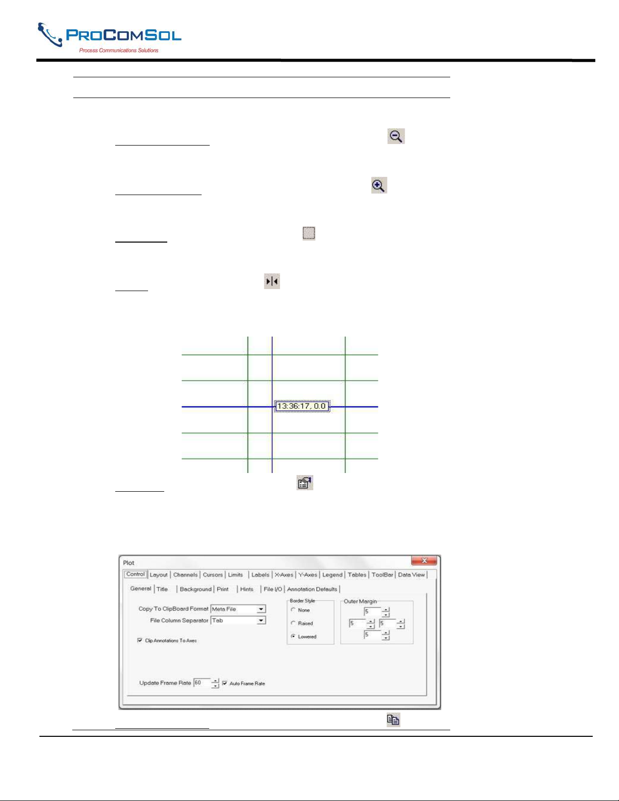
DevCom2000 User Manual
Step Action
shrink or enlarge the scale of either axis. By moving up or down,
left or right, the span of each axis is changed.
Zoom Out All Axis: The “Zoom Out All Axis” button - zooms out both the X-axis and Y-axis at the same time giving the
user a broader look at the graph.
Zoom In All Axis: The “Zoom In All Axis” button - - zooms in
both the X-axis and Y-axis at the same time giving the user view
over a smaller time period.
Zoom Box: The “Zoom Box” button - - changes the cursor
allowing the user to select a specific area of the graph to zoom in
on for a more detailed look.
Cursor: The “Cursor” button - - adds a cursor to the screen that
gives the coordinates of the graph at a certain time. Clicking and
moving the cursor can give the coordinates of any point on the
graph. See below for an example of using the “Cursor” tool:
Properties: The “Properties” button - - brings up the
“Properties” dialog box which gives the user the ability to
customize the graph as desired. Below is an example of one of the
“Properties” tabs:
Copy To Clipboard: The “Copy To Clipboard” button - - copies
MAN-1010 10/21/2021 Providing Advanced Process Communication Page 77
Products Since 2005
Find Quality Products Online at: [email protected]
www.GlobalTestSupply.com
Page 78
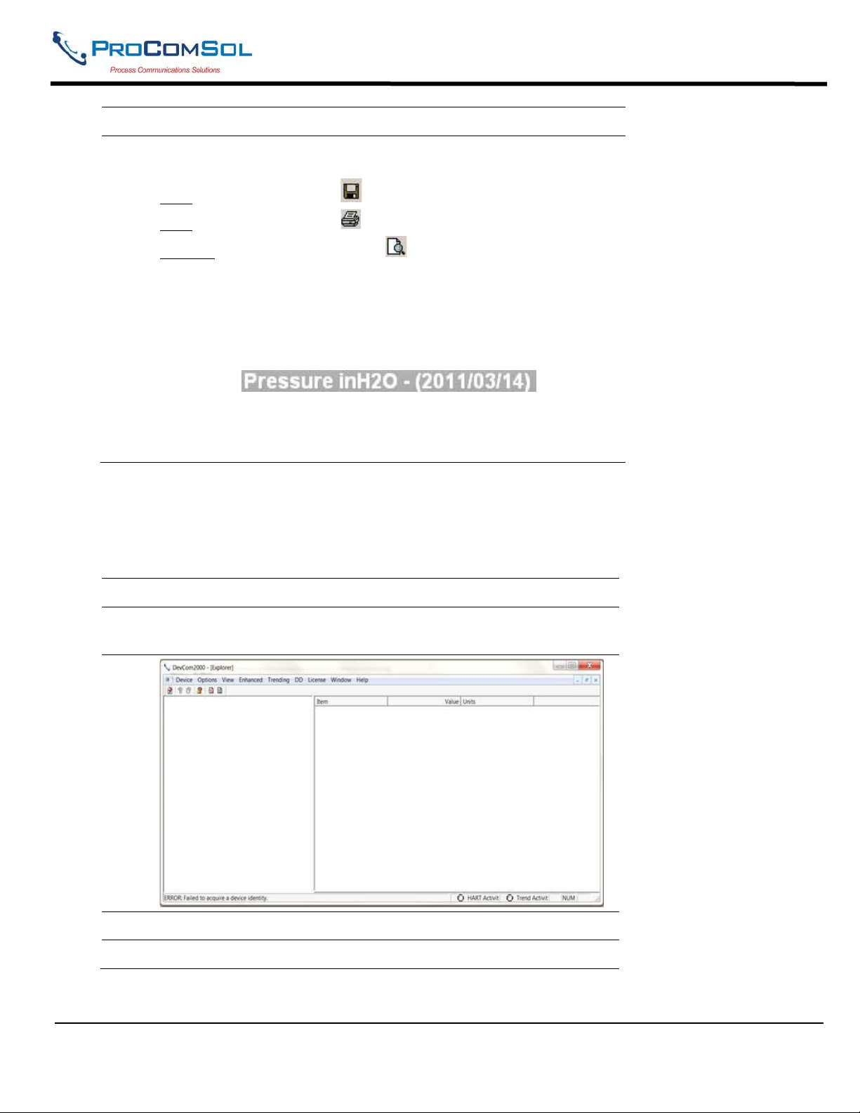
DevCom2000 User Manual
Step Action
the graph to the clipboard to allow the graph to be pasted into
documents like a report.
Save: The “Save” button - - saves the graph as a “*.bmp”.
Print: The “Print” button - - prints the graph.
Preview: The “Preview” button - - gives a print preview of the
graph.
Title: The title gives the name of the parameter being trended, the
units that the parameter is being measured in, and the date(s) of the
graph.
(Parameter) (Units) - (Date)
Axis: The Y-axis is the units of the parameter. The X-axis is the
time in HH:MM:SS format.
Redraw: This section is disabled for View Current Trend.
6.12.3 View Past Trends
DevCom2000 keeps a list of trends that have been done in the past. These trends are saved so that they can be
viewed at a later date. To select a trend to be viewed perform the following steps:
Step Action
1 Ensure that the application is running, you do not have to be
connected to a device to use View Past Trends.
2 Select Trending View Past Trends from the main window.
3 The Select Trend To Graph dialog will open.
MAN-1010 10/21/2021 Providing Advanced Process Communication Page 78
Products Since 2005
Find Quality Products Online at: [email protected]
www.GlobalTestSupply.com
Page 79
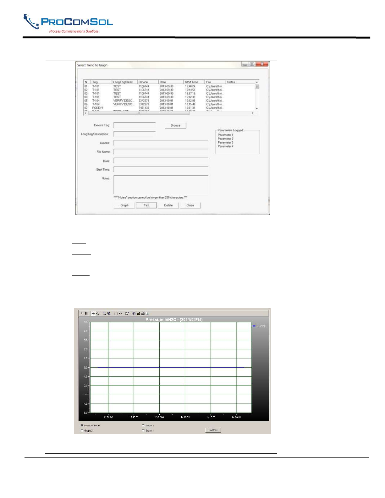
DevCom2000 User Manual
Step Action
This dialog box is very similar to the “Download/View” dialog
box.
Data: Opens the text file where the data has been saved.
Delete: Deletes a previous trend from the database.
Close: Closes the dialog box.
Trend: Opens the saved Trend and displays it graphically. Select a
trend to graph and click “Trend”.
4 The DevCom2000 Trend dialog opens up when “Trend” is
selected.
The user can manipulate the graph as desired. “Tracking” is the
term used to describe how the graph control follows the data,
MAN-1010 10/21/2021 Providing Advanced Process Communication Page 79
Products Since 2005
Find Quality Products Online at: [email protected]
www.GlobalTestSupply.com
Page 80
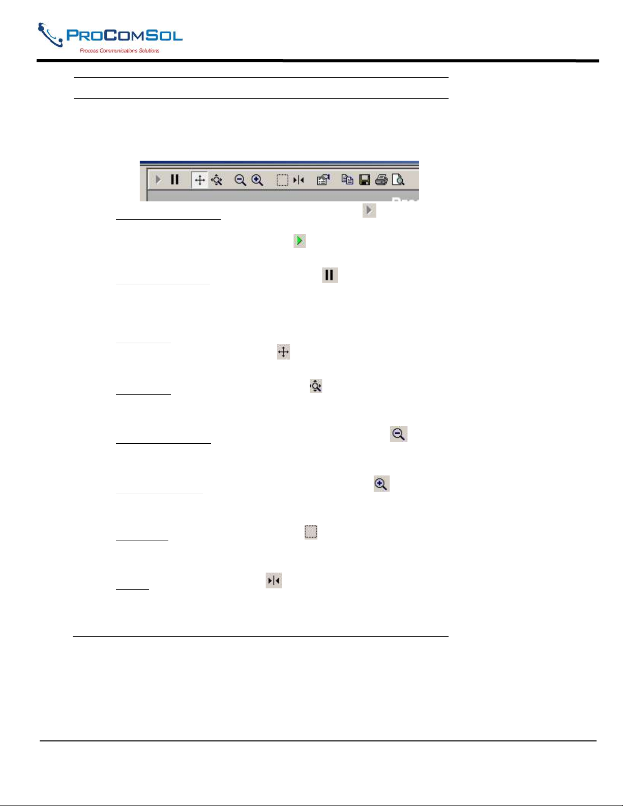
DevCom2000 User Manual
Step Action
changing the axis in real time so that all of the data is shown.
Below are the specific parts of the graph:
Tool Bar: There are multiple things that the user can do with the
graph.
Resume All Tracking: The “Resume All” button - - is grayed
out while tracking. If either axis is changed or the “Pause” button
is pressed, this will be come green - - Pressing “Resume All
Tracking” will resume the tracking on the graph.
Pause All Tracking: The “Pause” button - - pauses the graph in
its current state. Data is still added, however the current X-axis
and Y-axis spans no longer change. Pressing the “Resume” button
will continue tracking.
Scroll Axis: This is the default way to scroll both the X and Y-
axis. The “Scroll Axis” button - - allows the user to scroll in
both directions on the graph.
Zoom Axis: The “Zoom Axis” button - - allows the user to
shrink or enlarge the scale of either axis. By moving up or down,
left or right, the span of each axis is changed.
Zoom Out All Axis: The “Zoom Out All Axis” button - zooms out both the X-axis and Y-axis at the same time giving the
user a broader look at the graph.
Zoom In All Axis: The “Zoom In All Axis” button - - zooms
in both the X-axis and Y-axis at the same time giving the user
view over a smaller time period.
Zoom Box: The “Zoom Box” button - - changes the cursor
allowing the user to select a specific area of the graph to zoom in
on for a more detailed look.
Cursor: The “Cursor” button - - adds a cursor to the screen that
gives the coordinates of the graph at a certain time. Clicking and
moving the cursor can give the coordinates of any point on the
graph. See below for an example of using the “Cursor” tool:
MAN-1010 10/21/2021 Providing Advanced Process Communication Page 80
Products Since 2005
Find Quality Products Online at: [email protected]
www.GlobalTestSupply.com
Page 81
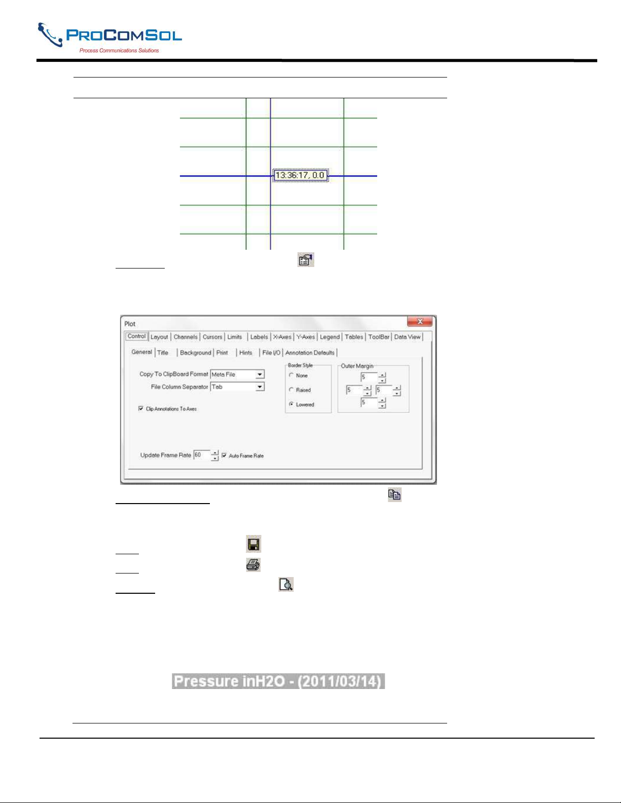
DevCom2000 User Manual
Step Action
Properties: The “Properties” button - - brings up the
“Properties” dialog box which gives the user the ability to
customize the graph as desired. Below is an example of one of the
“Properties” tabs:
Copy To Clipboard: The “Copy To Clipboard” button - copies the graph to the clipboard to allow the graph to be pasted
into documents like a report.
Save: The “Save” button - - saves the graph as a “*.bmp”.
Print: The “Print” button - - prints the graph.
Preview: The “Preview” button - - gives a print preview of the
graph.
Title: The title gives the name of the parameter being trended, the
units that the parameter is being measured in, and the date(s) of
the graph.
(Parameter) (Units) - (Date)
Axis: The Y-axis is the units of the parameter. The X-axis is the
time in HH:MM:SS format.
MAN-1010 10/21/2021 Providing Advanced Process Communication Page 81
Products Since 2005
Find Quality Products Online at: [email protected]
www.GlobalTestSupply.com
Page 82
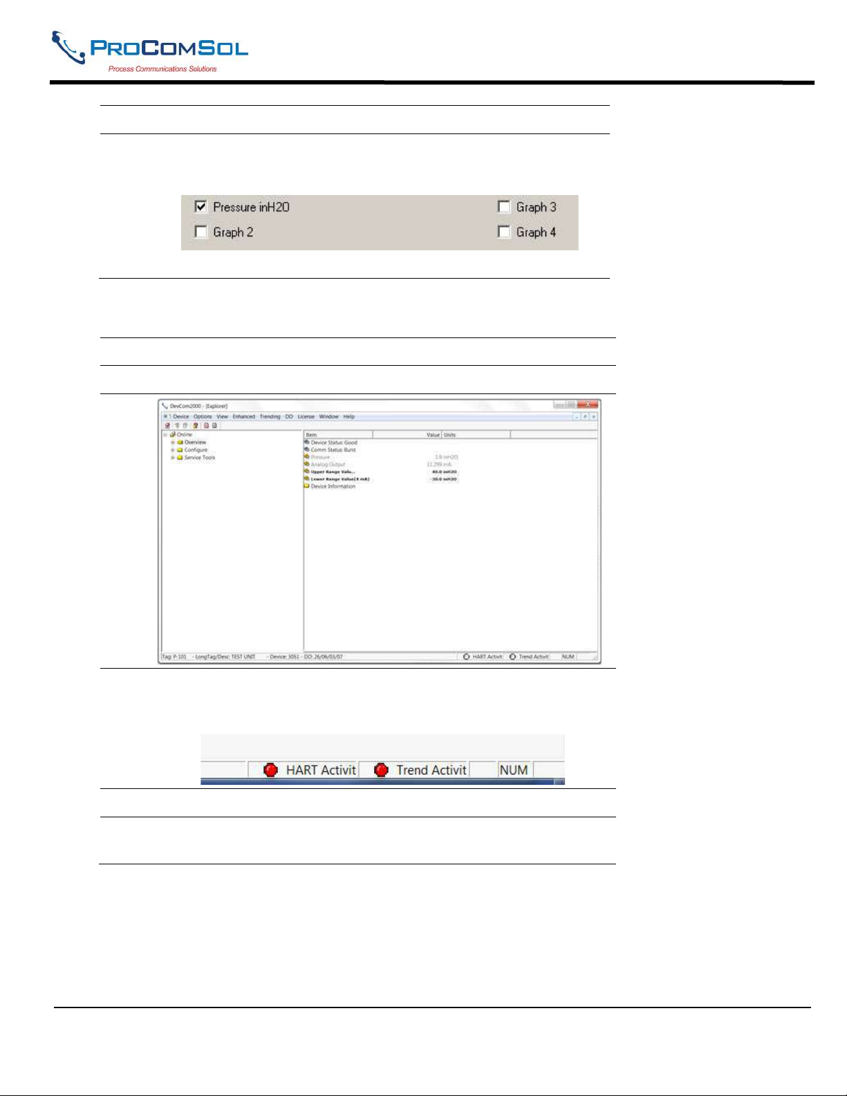
Redraw:
Step Action
By clicking the check box for a parameter u can show one or four
at the same time for easy comparison over a period of time.
Click “Redraw” and the parameters checked will be shown.
6.12.4 Stop Current Trend
Step Action
1 Ensure that the application is running and is connected to a device.
DevCom2000 User Manual
Up to four parameters can be trended at the same time.
2 Ensure that a trend is in progress. The “Trend Activity” light at the
bottom of the screen is on if a trend is in progress. If not then the
light will be off.
3 Select Trending Stop Current Trend from the main window.
4 You will be asked if you want to stop the current trend. Click
“Yes”. This will stop the current trend.
MAN-1010 10/21/2021 Providing Advanced Process Communication Page 82
Products Since 2005
Find Quality Products Online at: [email protected]
www.GlobalTestSupply.com
Page 83
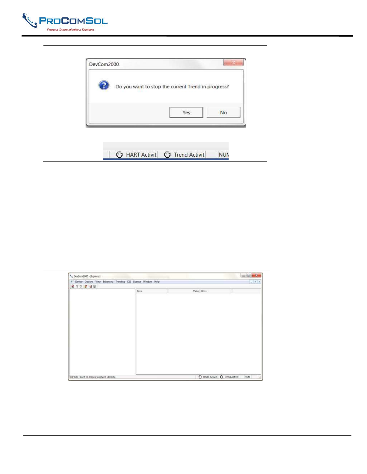
DevCom2000 User Manual
Step Action
5 The “Trend Activity” light will now be off.
6.13 DD Functions
6.13.1 Adding a DD
DevCom2000 allows the user to add a DD to the library when necessary. Each DD must be in its appropriate
destination for DevCom2000 to find the DD. The format is: “C:\HCF\DDL\Library\xxxxxx\yyyy\” where
“xxxxxx” represents the manufacturer ID and “yyyy” represents the device ID. The user does not need to add
the directory structure, DevCom2000 does that automatically. To add a DD perform the following steps:
Step Action
1 Ensure that the application is running, you do not have to be
connected to a device to use Add DD.
2 Select DD Add DD from the main window.
3 The Add DD dialog will open.
MAN-1010 10/21/2021 Providing Advanced Process Communication Page 83
Products Since 2005
Find Quality Products Online at: [email protected]
www.GlobalTestSupply.com
Page 84
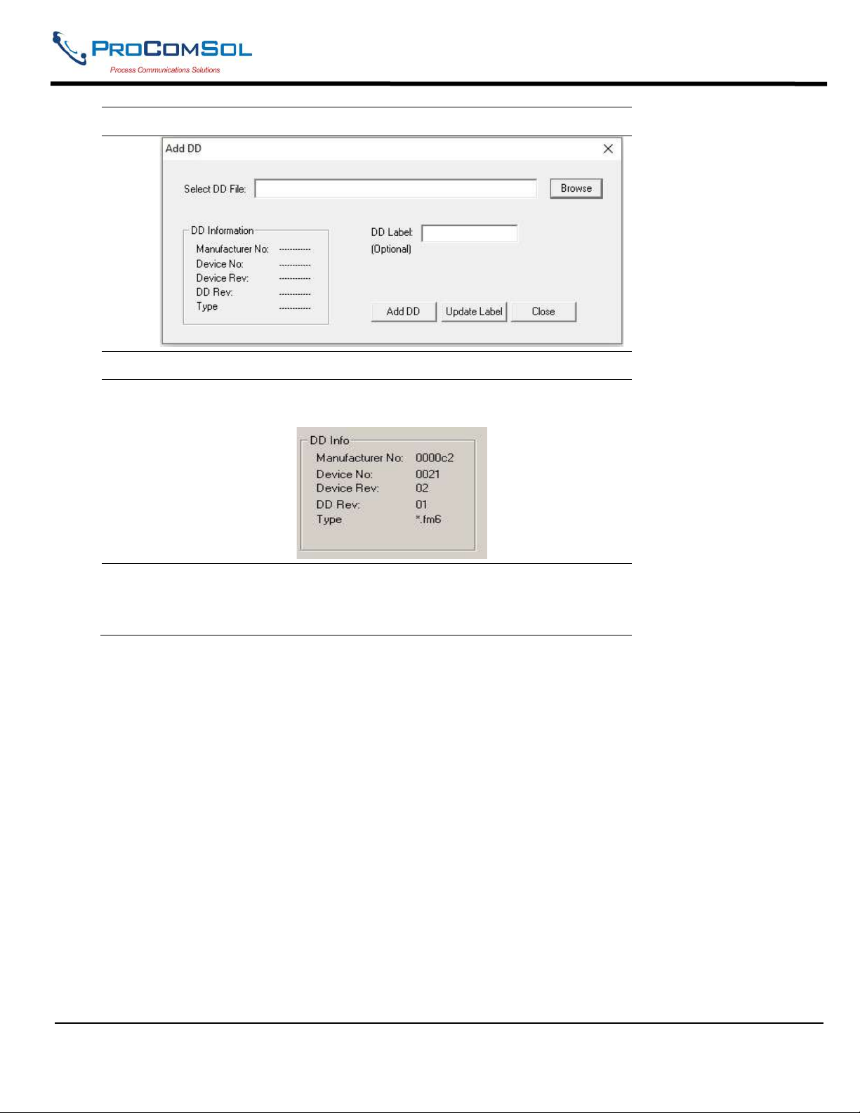
DevCom2000 User Manual
Step Action
4 Click “Browse” and go to the location of the DD that is to be added.
5 The “DD Info” section will be populated. Confirm that it is the
correct DD. Below is an example of 0000c2/0021/0201.fm6:
6 Input a “Label” for the DD if necessary. If not, Click “Add DD” to
add the DD to the library.
6.13.2 Updating a DD Label
DevCom2000 allows the user to add a Label for a DD if there is not one already defined. Below is an
example:
MAN-1010 10/21/2021 Providing Advanced Process Communication Page 84
Products Since 2005
Find Quality Products Online at: [email protected]
www.GlobalTestSupply.com
Page 85
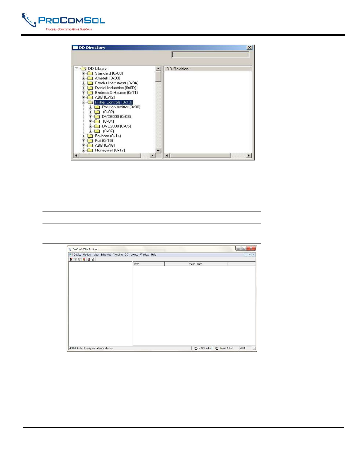
DevCom2000 User Manual
The manufacturer ID of Fisher Controls is 000013. Device IDs 0002, 0004, and 0007 all do not have a
label. This is when updating a DD label is useful. To update the label perform the following steps:
Step Action
1 Ensure that the application is running, you do not have to be
connected to a device to use Add DD.
2 Select DD Add DD from the main window.
3 The Add DD dialog will open.
MAN-1010 10/21/2021 Providing Advanced Process Communication Page 85
Products Since 2005
Find Quality Products Online at: [email protected]
www.GlobalTestSupply.com
Page 86
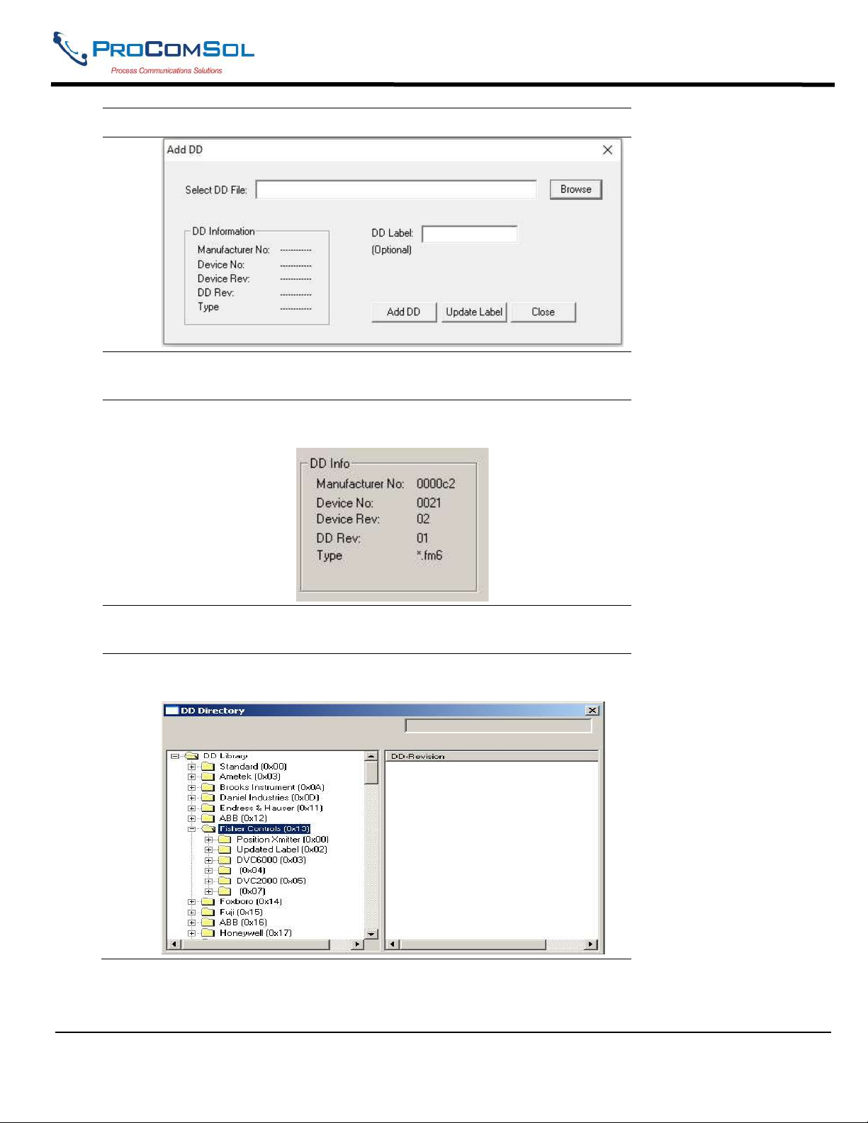
DevCom2000 User Manual
Step Action
4 Click “Browse” and go to the location of the DD that is to have the
label updated.
5 The “DD Info” section will be populated. Confirm that it is the
correct DD. Below is an example of 0000c2/0021/0201.fm6:
6 Input a “Label” for the DD if necessary. Click “Update Label” to
update the label.
7 Below is the new “Available DDs” sections where 000013/0002 is
given the label “Updated Label”:
6.13.3 DD Library Updates
The DD Library is updated generally every quarter. Users are notified by email when this occurs. You can
also check for updates by clicking DD LibraryCheck for Updates. DevCom2000 will then contact the
MAN-1010 10/21/2021 Providing Advanced Process Communication Page 86
Products Since 2005
Find Quality Products Online at: [email protected]
www.GlobalTestSupply.com
Page 87
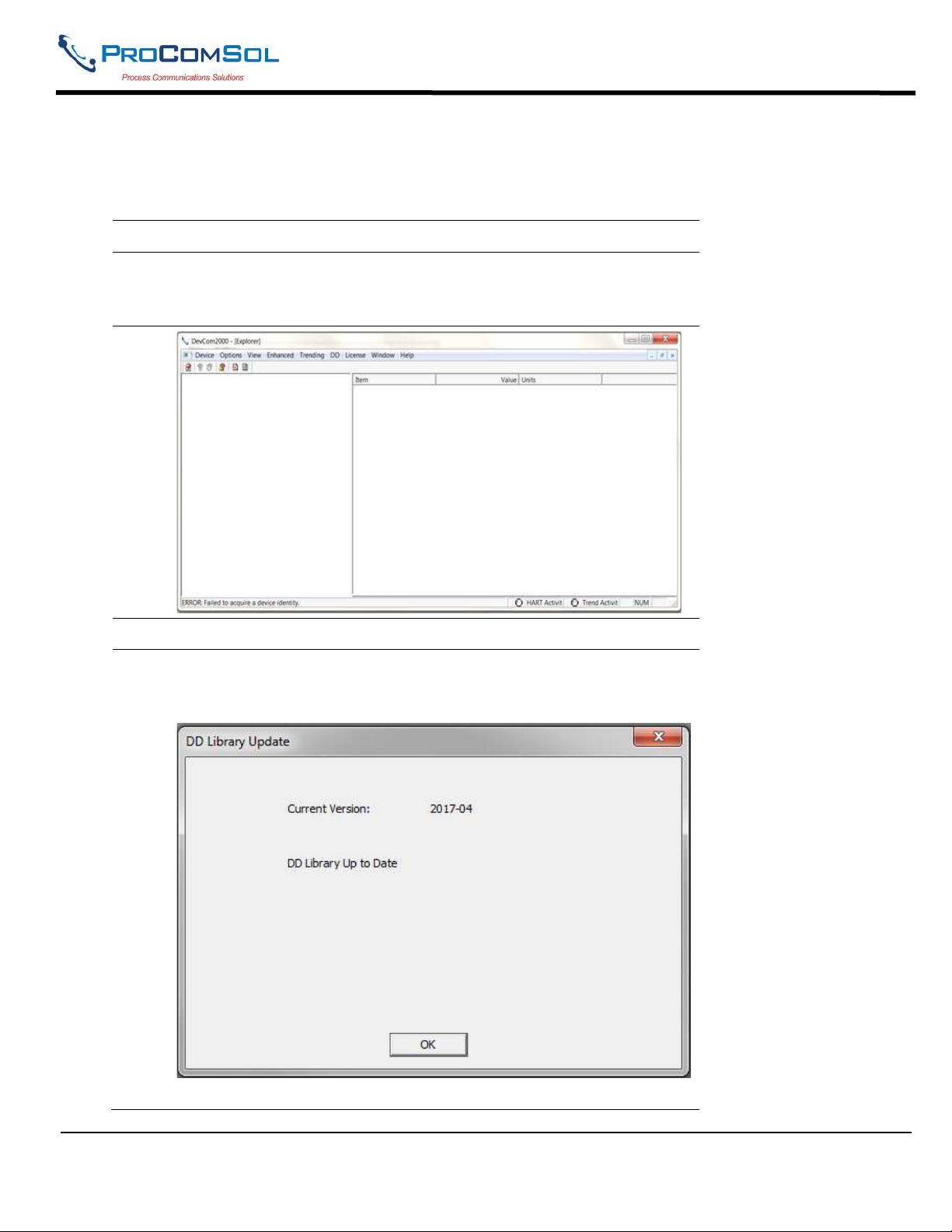
DevCom2000 User Manual
ProComSol DD Library Server and determine if a new DD Library is available. Note that you must have a
valid DD Library Subscription.
To check for DD Library updates perform the following steps:
Step Action
1 Ensure that the application is running, you do not have to be
connected to a device to use Check for Updates. However you do
need internet access.
2 Select DD Check for Updates from the main window.
3 The DD Library Update dialog box will open. What is displayed
is based on the Current DD Library Version, Available DD Library
Version, and status of the DD Library Subscription for this license.
DD Library is current, no update required.
MAN-1010 10/21/2021 Providing Advanced Process Communication Page 87
Products Since 2005
Find Quality Products Online at: [email protected]
www.GlobalTestSupply.com
Page 88
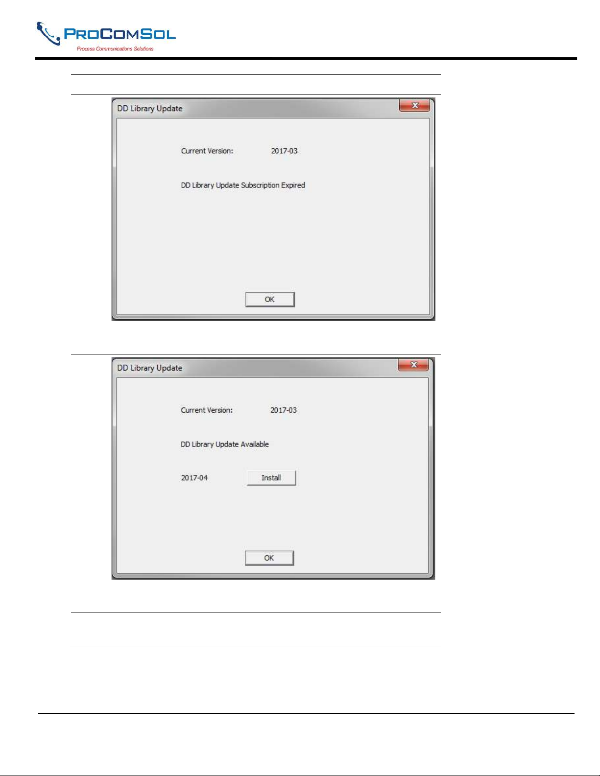
DevCom2000 User Manual
Step Action
DD Library subscription expired for this license. Contact
ProComSol to renew your subscription.
4
DD Library Update is available. Press “Install” to download the
new library.
5 While the DD Library download and installation is occurring, a bar
shows progress:
MAN-1010 10/21/2021 Providing Advanced Process Communication Page 88
Products Since 2005
Find Quality Products Online at: [email protected]
www.GlobalTestSupply.com
Page 89
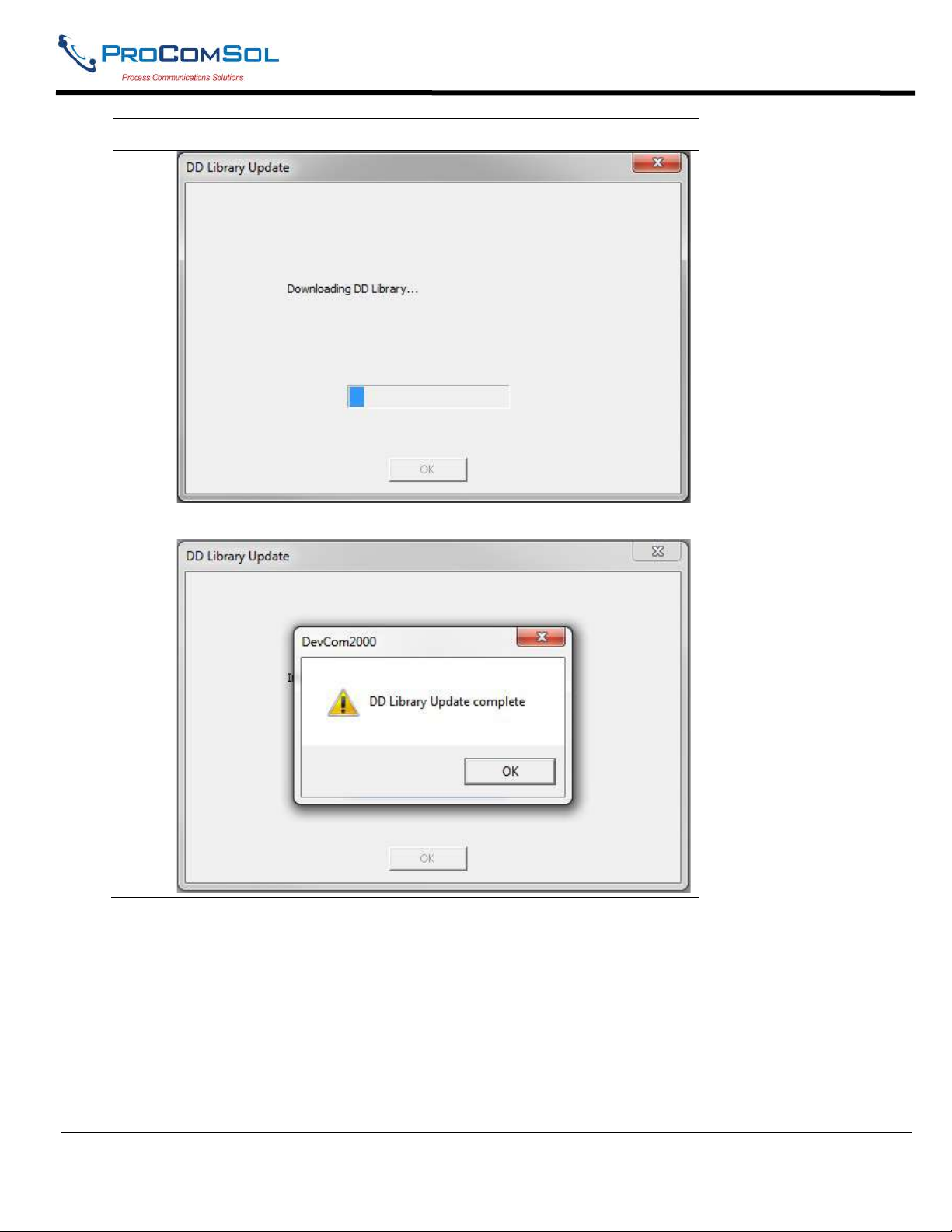
DevCom2000 User Manual
Step Action
6 The user is notified when the download and installation is complete:
6.14 Cloud
DevCom2000 can be setup to use the Cloud for storing saved device Configuration files. It can also be used to save
Trend files and Calibration Check files. The Cloud acts as data backup and platform for sharing data within a
defined Group. A Cloud subscription is required for Cloud features.
6.14.1 Options
Click Cloud->Options to open the Cloud Options dialog box.
MAN-1010 10/21/2021 Providing Advanced Process Communication Page 89
Products Since 2005
Find Quality Products Online at: [email protected]
www.GlobalTestSupply.com
Page 90
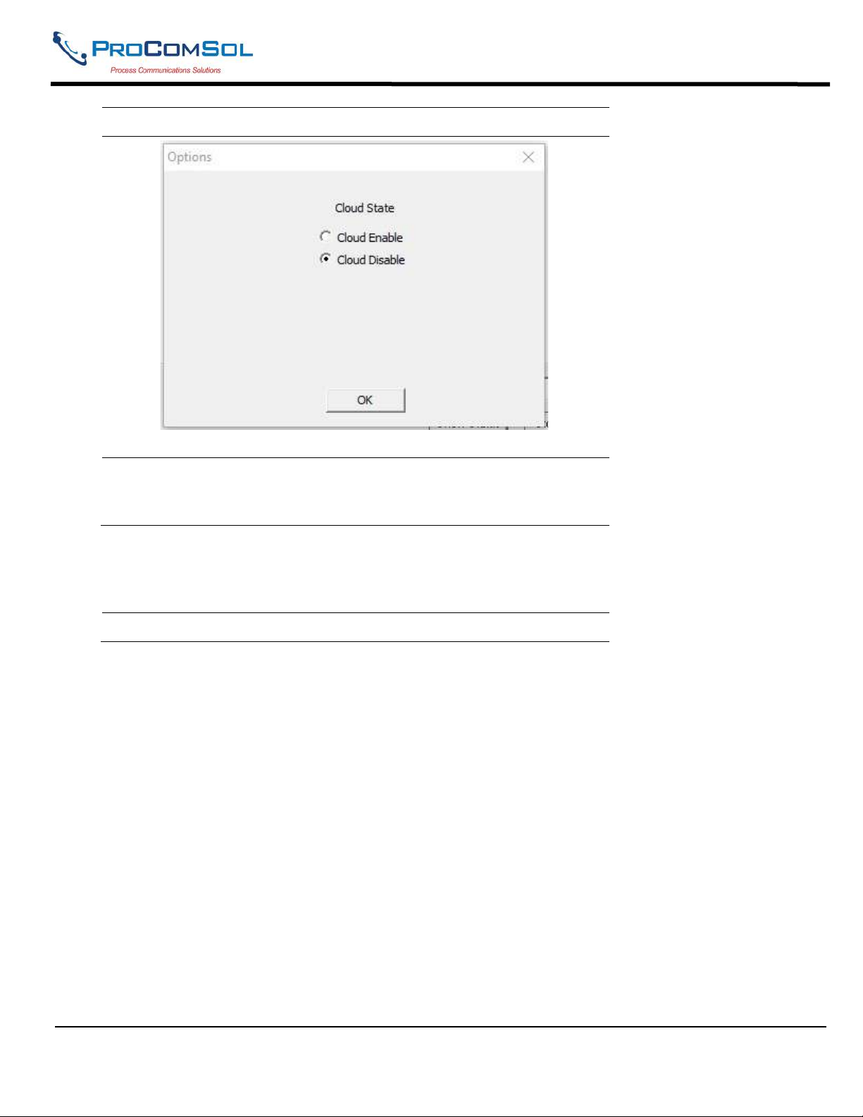
DevCom2000 User Manual
Step Action
1
When first opened, the current cloud state is shown.
2 Click Enable/disable as needed and click “OK” when done.
When first enabled, go to the Cloud->User dialog box to setup
the user.
6.14.2 User
Click Cloud->User to open the Cloud User Settings dialog box.
Step Action
MAN-1010 10/21/2021 Providing Advanced Process Communication Page 90
Products Since 2005
Find Quality Products Online at: [email protected]
www.GlobalTestSupply.com
Page 91
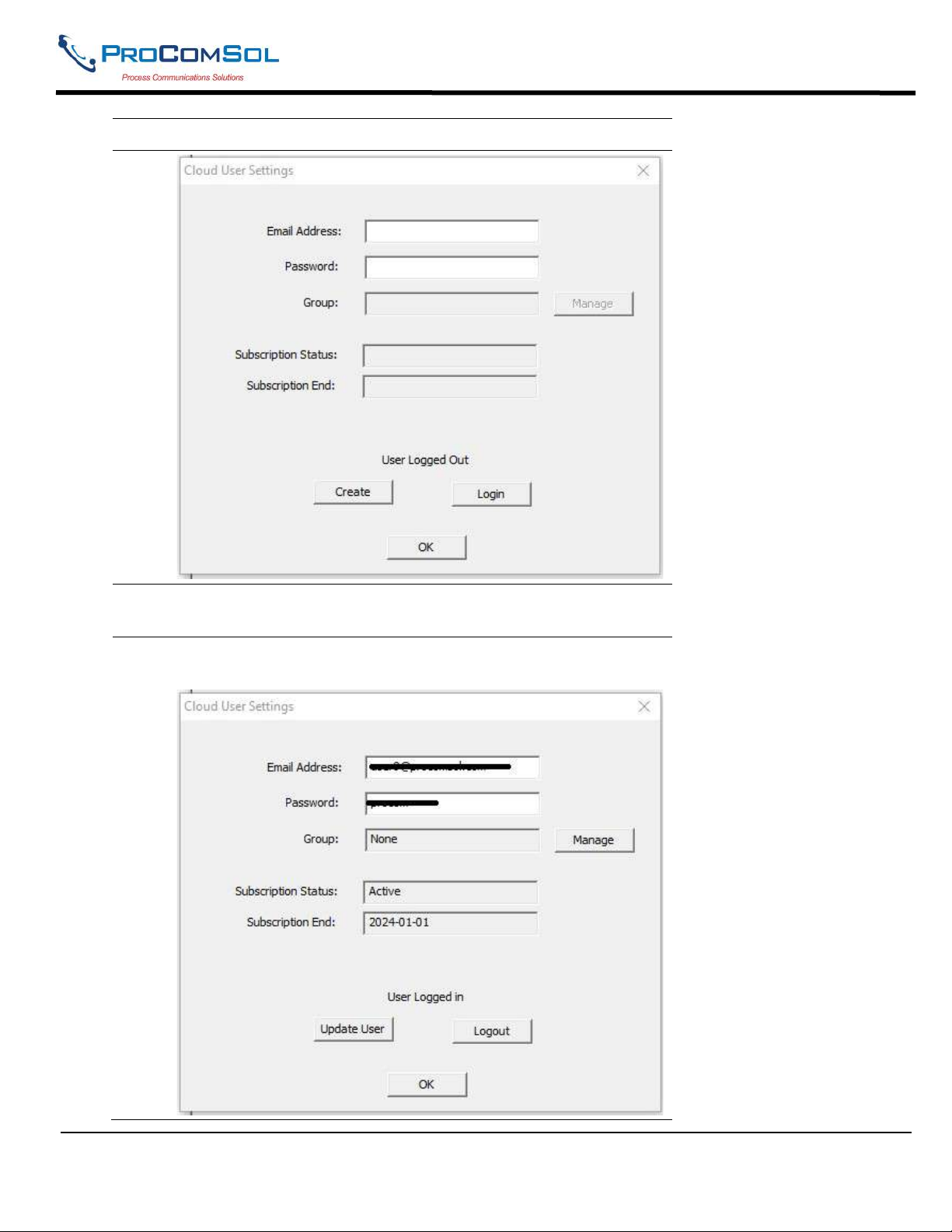
DevCom2000 User Manual
Step Action
1
2 To create a new user, enter an email address and password, then
click “Create”.
3 If successful, a success message is shown and then the Cloud
User Settings dialog box is updated with the data for the user:
MAN-1010 10/21/2021 Providing Advanced Process Communication Page 91
Products Since 2005
Find Quality Products Online at: [email protected]
www.GlobalTestSupply.com
Page 92
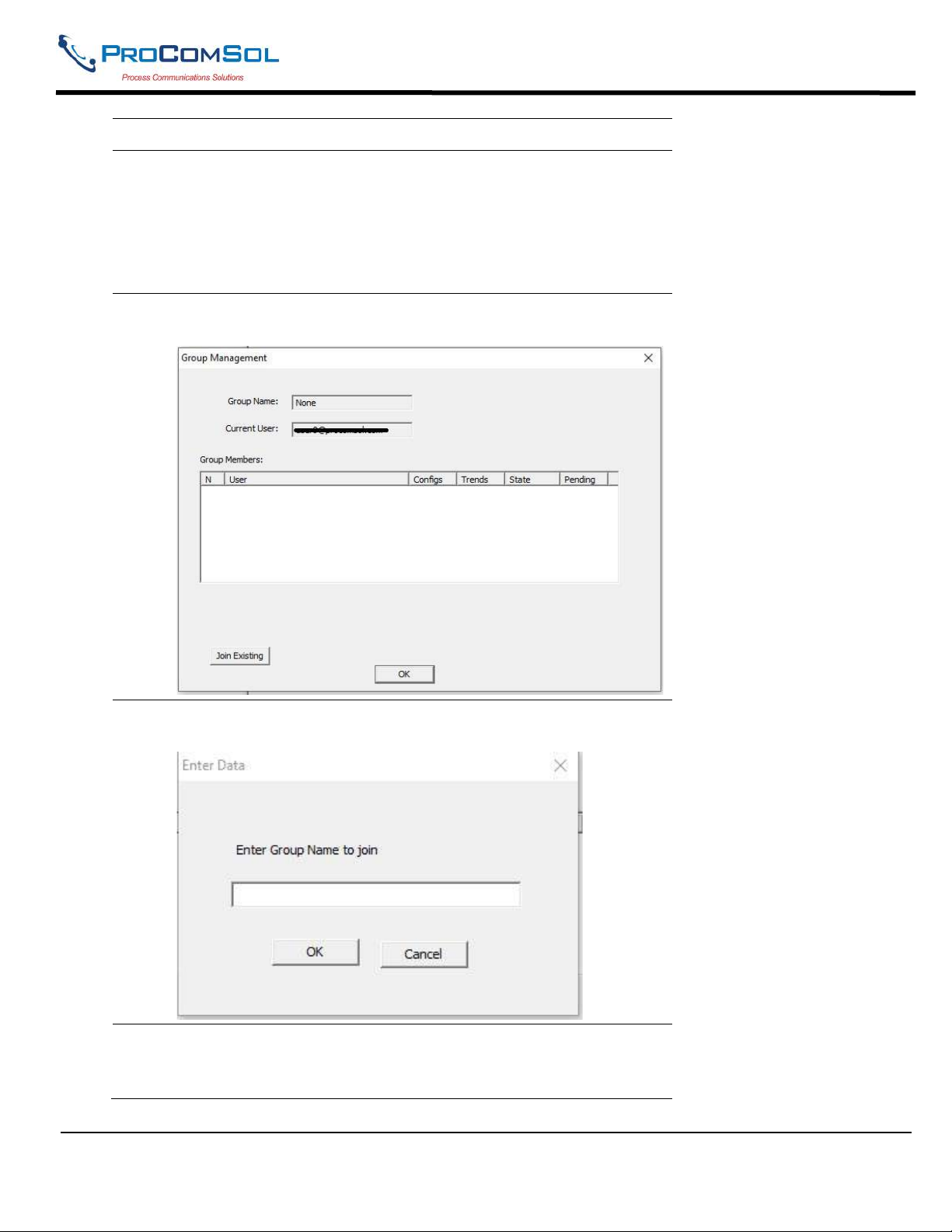
DevCom2000 User Manual
Step Action
Note the subscription status is “Active” and the end date of the
subscription is also shown. If the subscription is “Inactive” and
the current date is past the Subscription End date, contact
ProComSol to purchase or renew the Cloud Subscription.
Group shows what Groups this user is a member.
4 To manage Group memberships, click the “Manage” button.
The Group Management dialog box appears:
5 To join an existing group in your company, click the Join
Existing button. The Enter Group dialog box appears:
6 Enter the name of the group to join. The Group Administrator
will give you this name to use. After entering the name, click
OK.
MAN-1010 10/21/2021 Providing Advanced Process Communication Page 92
Products Since 2005
Find Quality Products Online at: [email protected]
www.GlobalTestSupply.com
Page 93
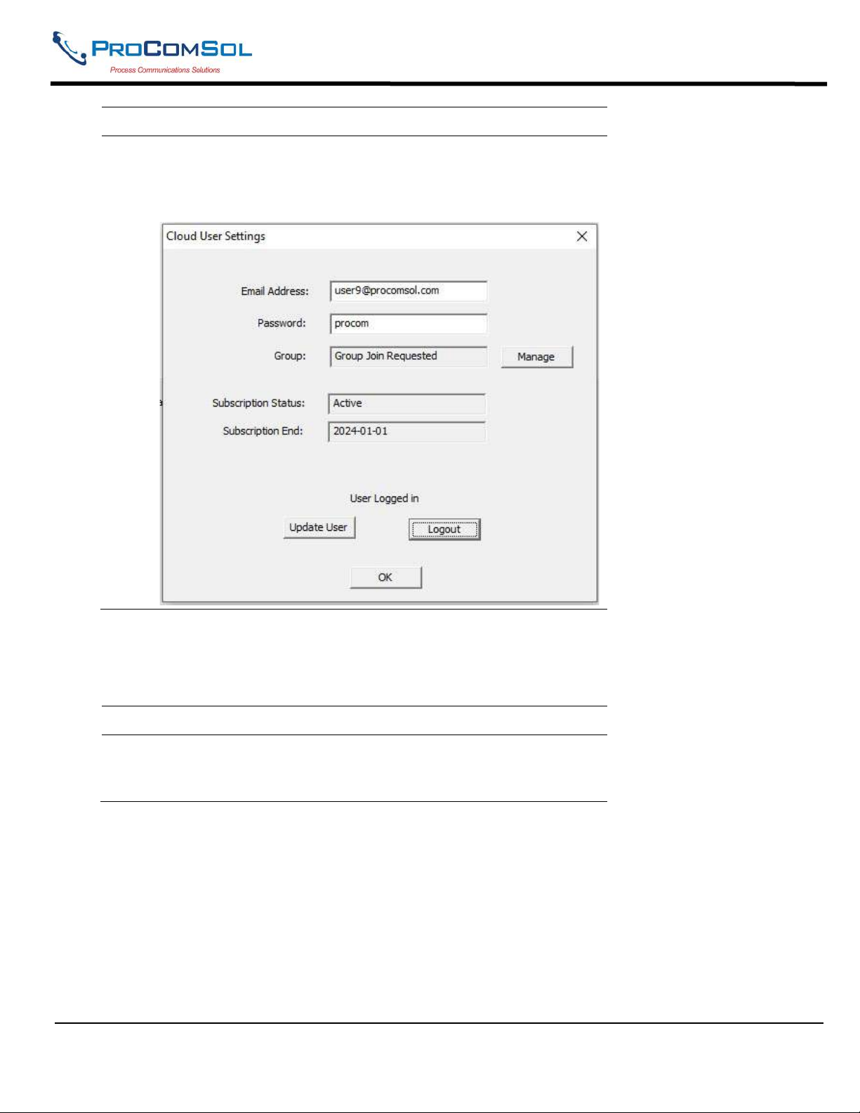
DevCom2000 User Manual
Step Action
7 You will see the Group <name> join requested message. The
join request was sent to the Group Administrator. The
Administrator will review your request and approve if
appropriate.
6.14.1 Group
Click Cloud->Group to open the Cloud Group Settings dialog box.
Step Action
1 In this example, the Administrator for the Testing Group has
logged in and clicked Cloud->Group. The Group Management
dialog box then appears:
MAN-1010 10/21/2021 Providing Advanced Process Communication Page 93
Products Since 2005
Find Quality Products Online at: [email protected]
www.GlobalTestSupply.com
Page 94
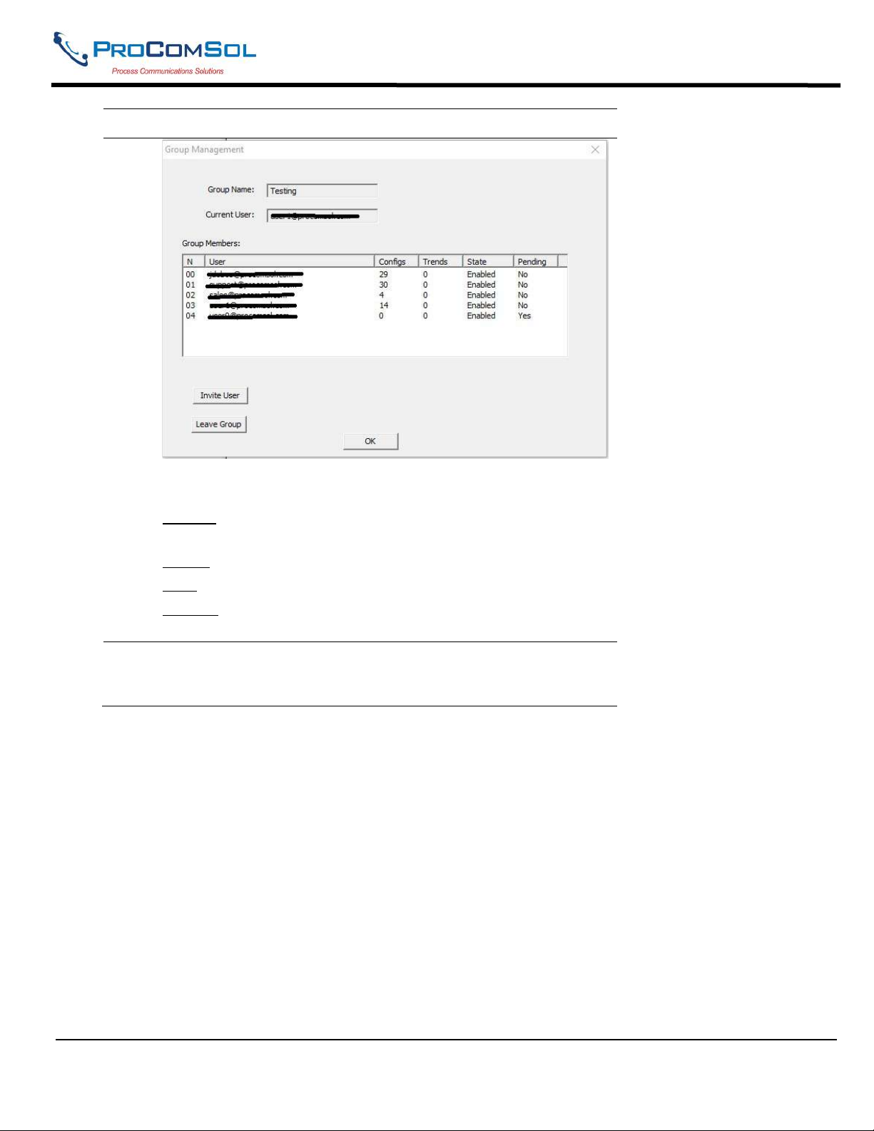
DevCom2000 User Manual
Step Action
Here the Administrator can see the status of each user in the
Group.
Configs - The number of saved Device Configurations for that
user.
Trends - The number of saved Trends for that user.
State - Whether this user is enabled or disabled.
Pending - It shows Yes when a join request was received by the
Administrator.
2 Double click on the user to perform various functions. When
double clicked the Group Admin dialog box
appears:
MAN-1010 10/21/2021 Providing Advanced Process Communication Page 94
Products Since 2005
Find Quality Products Online at: [email protected]
www.GlobalTestSupply.com
Page 95
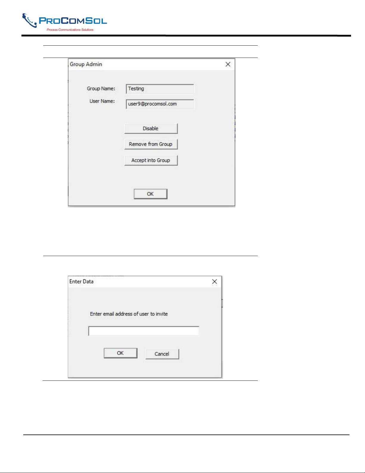
DevCom2000 User Manual
Step Action
Click Disable to disable the user from using the Cloud functions.
If the user was already disabled, this button will instead be
Enable.
Click Remove from Group to disconnect the user from Group.
Click Accept into Group to respond to a user join request.
3 Click Invite User to send an email to invite a user to join the
group.
MAN-1010 10/21/2021 Providing Advanced Process Communication Page 95
Products Since 2005
Find Quality Products Online at: [email protected]
www.GlobalTestSupply.com
Page 96

DevCom2000 User Manual
6.15 Licensing
The license file can be transferred easily to other computers. The process is a “Check-In/Check-Out” process.
When a license is on the computer, it is considered “Checked-Out”. When the license is on the license server, it is
considered “Checked-In”. When the license is “Checked-in”, it can be “Checked-Out” by other users. This enables
the license to be shared by many users, one at a time.
6.15.1 License Details
Click License->Details to get the LicenseID and Password information for the license. The information is very
important for troubleshooting and subscription services.
6.15.2 Check-In
To Check-In the license from the current computer to the License Server, perform the following steps:
Step Action
1 Verify your PC is connected to the Internet.
2 Select “Check-In” from the “License” Menu.
If the current computer is not licensed, an error message will
appear. If licensed, the program will contact the License Server
via the internet. It will check-in the license using the License ID
and Password used in Activation. The current computer will
then become un-activated.
6.16 HART-IP Communication
Step Action
1 Ensure that settings for HART-IP have been made in the
OptionsBasic menu. Note that a HART Modem is NOT required,
only Ethernet access to the HART-IP Gateway.
2
Click on “New Device” icon to start the connection process. The
following screen will appear.
MAN-1010 10/21/2021 Providing Advanced Process Communication Page 96
Products Since 2005
Find Quality Products Online at: [email protected]
www.GlobalTestSupply.com
Page 97
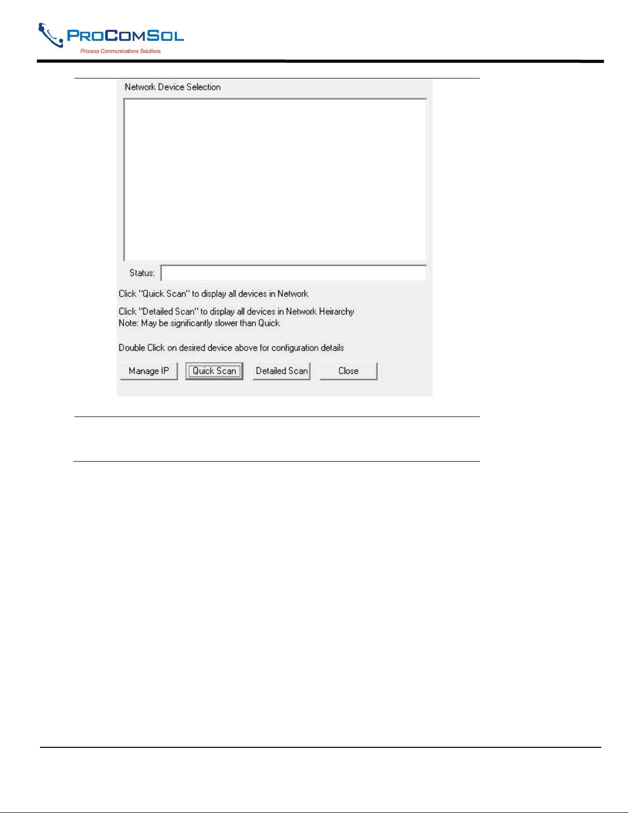
DevCom2000 User Manual
3
Click on “Quick Scan” to provide a simple list of all the devices on the
HART-IP network. Below is a sample screen:
MAN-1010 10/21/2021 Providing Advanced Process Communication Page 97
Products Since 2005
Find Quality Products Online at: [email protected]
www.GlobalTestSupply.com
Page 98
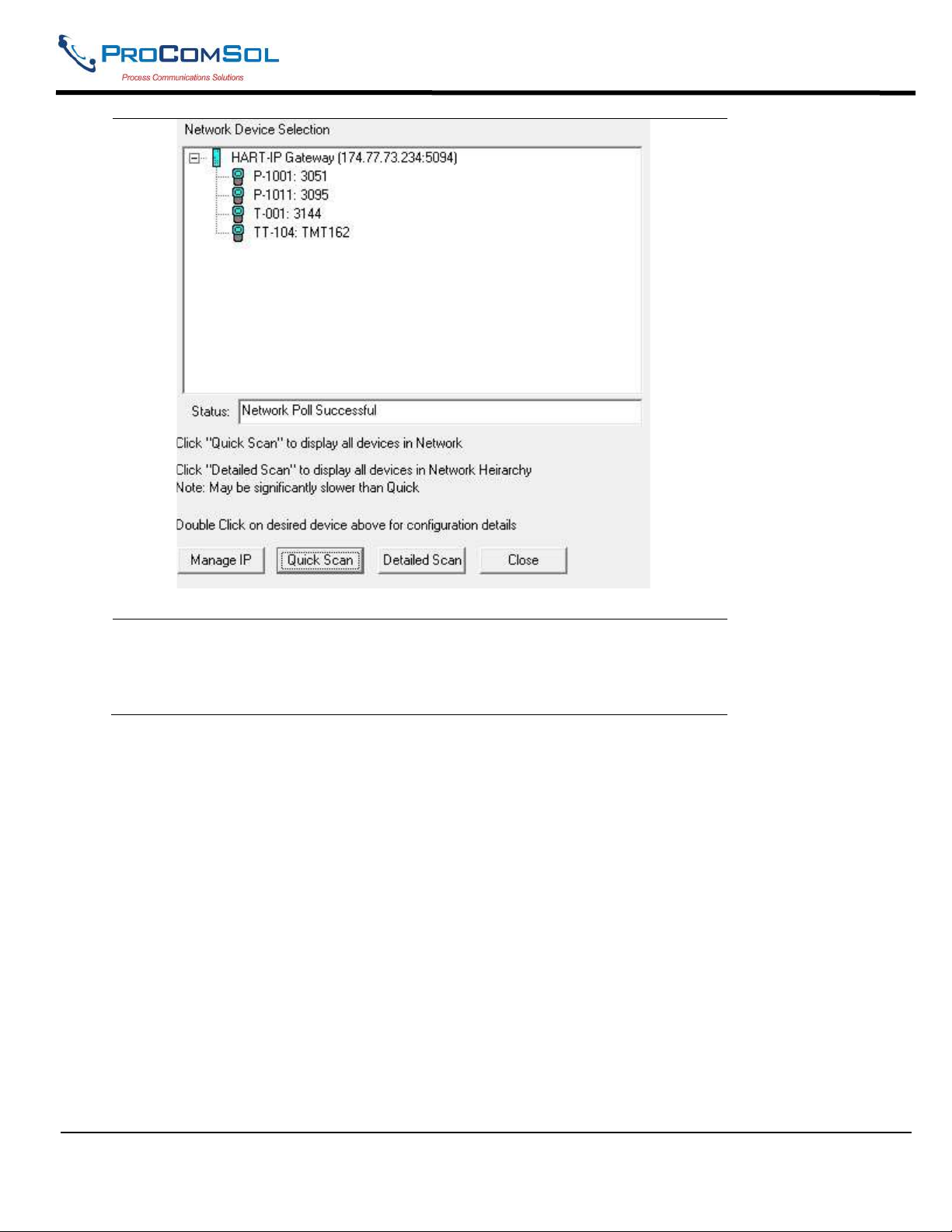
DevCom2000 User Manual
4
Click on “Detailed Scan” to display all the devices as a heirarchy. This
will show what transmitters are connected to each WirelessHART
adapter. Note that this listing may take significantly longer to generate
than the Quick Scan. Below is a sample screen.
MAN-1010 10/21/2021 Providing Advanced Process Communication Page 98
Products Since 2005
Find Quality Products Online at: [email protected]
www.GlobalTestSupply.com
Page 99
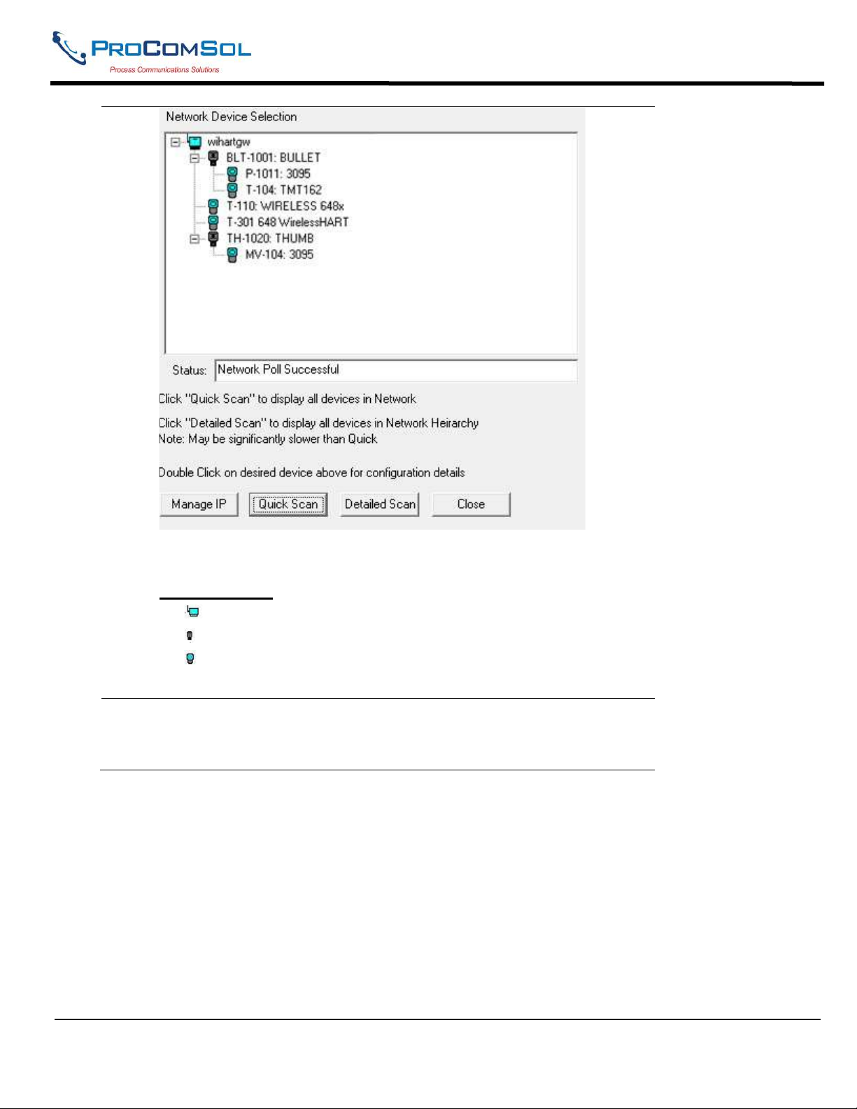
DevCom2000 User Manual
5
For both types of list displays, the following icons are used:
HART-IP Icons
= Gateway
= Adapter, WirelessHART
= Transmitter
Once a device list has been created, double click on the desired device
to configure/review using DevCom2000. Below is a sample screen:
MAN-1010 10/21/2021 Providing Advanced Process Communication Page 99
Products Since 2005
Find Quality Products Online at: [email protected]
www.GlobalTestSupply.com
Page 100
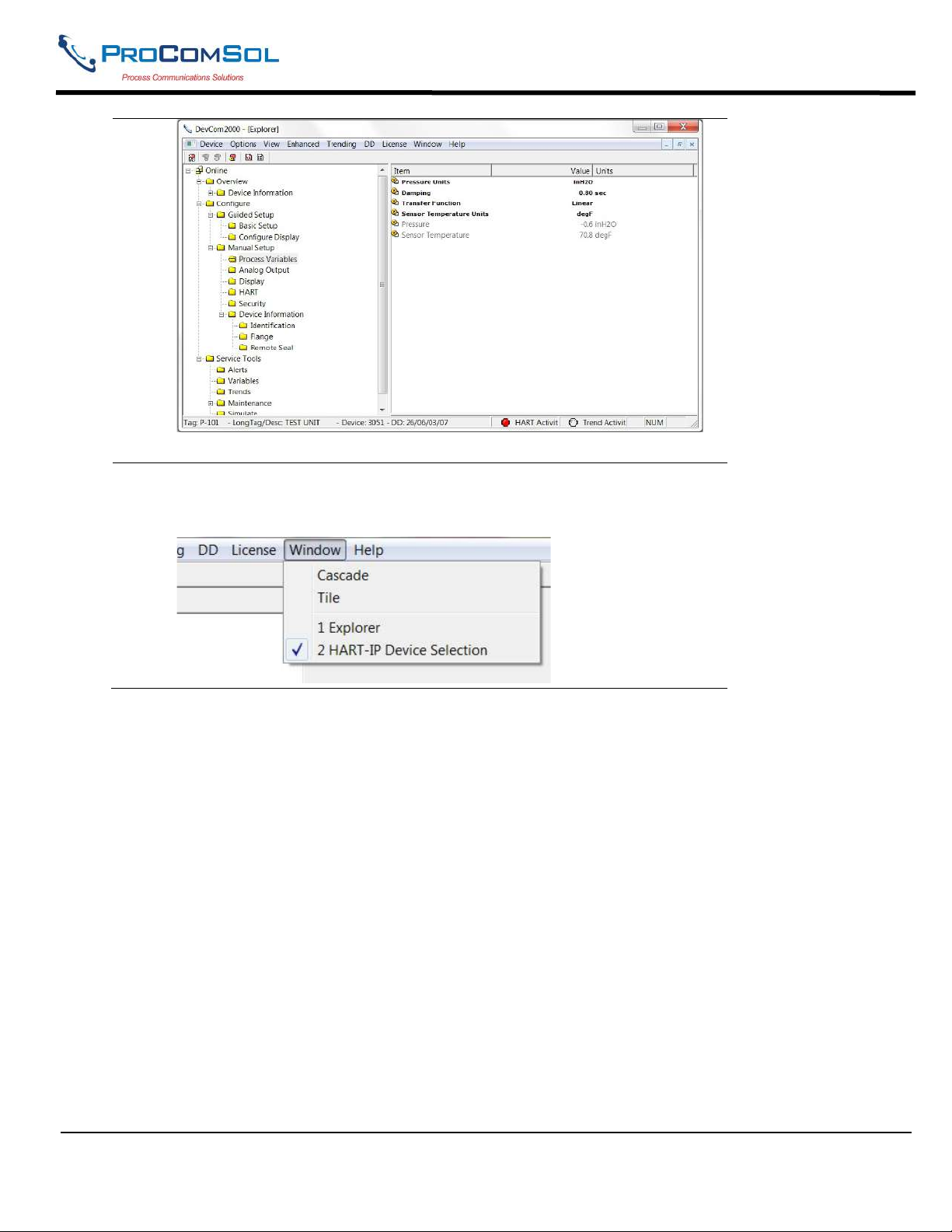
DevCom2000 User Manual
6
To switch to a different device on the WirelessHART network: Select
Window on the MENU bar, then click on HART-IP Device Selection
to bring up the Device Menu Tree again.
MAN-1010 10/21/2021 Providing Advanced Process Communication Page 100
Products Since 2005
Find Quality Products Online at: [email protected]
www.GlobalTestSupply.com
 Loading...