

Page 1

HM-USB-PWR User Manual
HM-USB-PWR User Manual
Introduction
The HM-USB-PWR HART® Modem is designed to connect PC’s to HART networks.
Application software can then configure, monitor, and document HART based
instrumentation. The power supply feature can also power HART transmitters.
Software Drivers
Before use, a USB Virtual Serial Port must be installed on the PC. Insert the enclosed
CD into your PC. The USB Virtual Serial Port driver should install automatically. Once
the driver is installed, you can connect the HM-USB-PWR to the USB port on your PC.
Windows
After the HM-USB-PWR is connected and the New Hardware Found wizard is finished,
the following will appear at the bottom of the screen:
Note: A completion message may not appear on some system.
COM Port Assignment
After installing, and with the HM-USB-PWR still connected to the PC, go to Start ->
Settings -> Control Panel -> System -> Hardware -> Device Manager -> Ports, to see
what COM port number was assigned to the modem by the Windows operating system.
The port labeled “USB Serial Port” is the assigned port.
Alternatively, if you click on the “Your devices are ready to use” message, the assigned
COM port will be listed.
This port assignment can be changed by the user. From the “Device Manager” menu,
select the USB Serial Port you wish to change. From the “Properties” page, select “Port
Settings”. Then select “Advanced”. The COM port can be set in the range 1-256.
Operating Modes
Three different operating modes are available - Power + Modem
Modem Only, and Power Only. Each requires different cable setups.
Power + Modem
Connect the supplied HART cable to the “Modem + Power” connector on the HM-USBPWR. The 24Vdc LED should illuminate.
Connect the Red connector to the positive (+) terminal of the HART Transmitter.
Connect the Black connector to the negative (-) terminal of the HART transmitter. The
MAN-1044 6/15/2017 Our Quality Management System is Page 1
ISO 9001:2008 Certified
Page 2
HM-USB-PWR User Manual
HART Loop resistor is built-in to the modem so an external resistor is not required for
this mode.
Modem Only
Connect the supplied HART cable to the “Modem Only” connector on the HM-USBPWR. The 24Vdc LED should be off.
Connect the Red connector to the positive (+) terminal of the HART Transmitter.
Connect the Black connector to the negative (-) terminal of the HART transmitter. Note
that the HART transmitter requires an external power supply and loop resistor in this
mode.
This mode is useful for communicating with WirelessHART devices that are battery
powered.
Power Only
Connect the supplied HART cable to the “Modem + Power” connector on the HM-USBPWR. The 24Vdc LED should illuminate.
Connect the Red connector to the positive (+) terminal of the HART Transmitter.
Connect the Black connector to the negative (-) terminal of the HART transmitter. The
HART transmitter is now powered. The HART Loop resistor is built-in to the modem so
an external resistor is not required for this mode when using an external HART modem.
Current Measurement
You can measure the loop current without breaking the loop. Simply connect your
current meter to the “Current” test points on the HM-USB-PWR.
External HART Modem Option
With the HM-USB-PWR operating in the Power Only mode, an external HART modem
or HART Communicator can be connected to the “HART” test points. The loop resistor
is built-in so no external loop resistor is necessary.
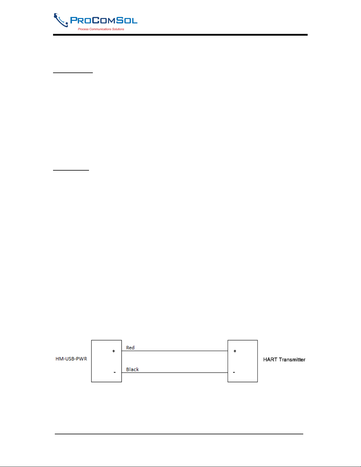
HART and Power Connections
Simply connect the modem to the HART transmitter observing power polarity. See
Figure 1.
Figure 1. HART and Power Connections
USB Connection
Connect the integral USB-A connector to any available USB port on your PC.
MAN-1044 6/15/2017 Our Quality Management System is Page 2
ISO 9001:2008 Certified
Page 3

HM-USB-PWR User Manual
LEDs
Two LEDs provide operating status information – 24Vdc and USB Power.
USB Power
This should illuminate when the USB connector is connected to your PC.
24Vdc
This should illuminate when the HART cable is connected to the “Modem + Power”
connector. This means 24Vdc power is present on the cable ends.
PC Power
No external power sources are required for the HM-USB-PWR. Power is derived from
the USB connection to the PC.
AC Power
If a PC is not available, the HM-USB-PWR comes with an AC Adapter. Simply plug the
AC Adapter into a power outlet and then plug the USB cable of the HM-USB-PWR into
the AC Adapter.
The USB Power LED will illuminate.
Test Software
Program “HM Test” is included on the installation CD to test the operation of the HMUSB-PWR. Launch the program from the CD or from the installed icon. Enter the com
port that was assigned to the modem by Windows. Then select “Poll HART Network” to
connect to a HART device. The program sends HART Command 0 to determine what
transmitters are connected to the loop. The “Status” box will indicate successful
operation of the HM-USB-PWR in your system. Consult the “Troubleshooting” section
of this manual if test failure.
Troubleshooting
Verify the following:
1. Com port number in application is the HM-USB-PWR com port number.
2. HART Transmitter has power.
3. If multi drop configuration, all HART transmitters in the loop have unique addresses.
4. HM-USB-PWR USB connector seated firmly in PC USB connector.
5. HM-USB-PWR HART connector seated firmly on the device.
Warranty
The HM-USB-PWR is warranted for 1 year for materials and workmanship. Contact
Support at ProComSol, Ltd if having trouble. An RMA (Return Material Authorization)
number obtained from ProComSol, Ltd is required on all returned items.
MAN-1044 6/15/2017 Our Quality Management System is Page 3
ISO 9001:2008 Certified
Page 4

HM-USB-PWR User Manual
Contact Information
ProComSol, Ltd
Process Communications Solutions
13001 Athens Ave.
Suite 220
Lakewood, OH 44107
USA
Phone: 216.221.1550
Fax: 216.221.1554
Email: sales@procomsol.com
support@procomsol.com
Web: www.procomsol.com
MAN-1044 6/15/2017 Our Quality Management System is Page 4
ISO 9001:2008 Certified
 Loading...