

Page 1

Contents
CONTENTS
CH1. MOTHERBOARD FEATURE...........................................................1
!SPECIFICATIONS ..........................................................................1
!POWER OFF CONTROL SOFTWARE .........................................3
!PACKAGING CHECK LIST ..........................................................3
CH2. SETUP GUIDE.....................................................................................4
!MAINBOARD LAYOUT DRAWING............................................4
!JUMPER & CONNECTOR SETTING ...........................................6
CONNECTOR SETTING ...............................................................6
PANEL - OTHER JUMPER SETTING ........................................10
CPU TYPE SELECT ....................................................................10
FAN CONNECTOR......................................................................18
!MEMORY INSTALLATION........................................................19
CH3. AWARD BIOS SETUP......................................................................20
!THE MAIN MENU .......................................................................22
!STANDARD CMOS SETUP.........................................................24
!BIOS FEATURES SETUP ............................................................25
!CHIPSET FEATURES SETUP .....................................................31
!POWER MANAGEMENT............................................................32
!PNP / PCI CONFIGURATION SETUP ........................................38
!INTEGRATED PERIPHERALS ...................................................40
!LOAD BIOS DEFAULT ...............................................................41
!LOAD SETUP DEFAULT ............................................................41
!SUPERVISOR / USER PASSWORD SETTING..........................41
!IDE HDD AUTO DETECTION....................................................42
✒
PENTIUM® II CPU INSTALLATION GUIDE ...................................P-1
REMARK
INTEL
®
is a registered trademark of Intel Corporation.
i
Page 2

Contents
All other brands and product names are trademarks registered trademarks of their
respective companies.
i
Page 3

B782/B783
Chapter 1
Motherboard Feature
SPECIFICATIONS
System Chipset
CPU Bus Speed
CPU Clock
Memory Subsystem
Integrated I / O
V/A VT82C691 chipset, Winbond 83877TF
®
Pentium
233MHz ~ 450MHz
Expandable to 384MB(3 banks) with 168-Pin
SDRAM(DIMM) Socket X3
Two high speed 16550 compatible serial ports, one
Multi-Mode Parallel Port fixed SPP/EPP/ECP
standard
Two PCI Bus master Ultra DMA/33 IDE port (up to 4
IDE Devices)
Support two 360KB / 720KB / 1.2MB / 1.44MB /
2.88MB / floppy disk driver
Support LS120 drives, ZIP 100 drives
Support two USB ports
Support IrDA TX / RX header
҈ 66/100 MHz CPU
BIOS
2MB Award PnP BIOS with enhanced ACPI feature
for PC98 compliance.
Supports Trend™ ChipAway AntiVirus.
DMI feature support
Support secondary device boot
1
Page 4

B782/B783
On-Board ESS1898
(Only For B782)
Expansion slot
EXTRA Function
Connector
Others
Dimension
One speaker, one MIC, one Lin in, one Game port
connector
Four PCI Master Slots & Two 16-bit ISA Slots
Support 3.3/5V PCI bus Interface
Suspend LED on/off
Win95 soft power off
External SMI
Wake up by ring
Wake On LAN
PS/2 Keyboard and PS/2 mouse Connector
Windows 98/95 Compatible
4-layer PCB, ATX size (305mm x 185mm)
2
Page 5

B782/B783
POWER OFF CONTROL SOFTWARE
The motherboard design supports software power off Control feature
through the SMM code in the BIOS under Win95 operating system
environment. This is ATX form factor feature and you should use ATX power
supply.
First, you should connect the power switch cable (provided by the ATX
case Supplier) to the Jumper on the motherboard. In the BIOS screen of
“POWER MANAGEMENT SETUP”, choose “User Defined”(or min power
saving or Max power saving)in “POWER MANAGEMENT” and choose
“Yes” in “PM Control by APM”.
In Windows 95 the “ SHUT DOWN “ option ,the computer’ s Power will
switch off automatically and put the PC in a suspend mode. This will be
indicated by a bunking power light. To restart the system , simply press the
Power Button.
In B782, ESS sound chipset is add-on. You can enjoy the 3D effect sound
without sound card. The user-friendly sound card control panel also is free.
You just install the software of sound control panel from our CD-title and enjoy
the clearly sound, when you get our motherboard - B782.
PACKAGING CHECK LIST
The motherboard comes securely packed in a durable box and shipping
carton. If any of the above items are missing or damaged , please contact your
supplier.
The motherboard contains:
Q’ TY Description
1 motherboard : B782/B783
1 CD-title
1 Cable
1 Cable
: Driver & AP
: Enhanced IDE connector
: F.D.D connector
3
Page 6

B782/B783
1 Manual : User’ s manual
4
Page 7

B782/B783
Chapter 2
SETUP GUIDE
B782 Motherboard Layout Drawing
T: Mouse
B: K/B
USB 1 / 2
T: LPT1
B:COM1/2
T: Game Port
B: Audio Port
JIR1
J4
JS1
ESS
Audio
ATX POWER
JFREQ1
SLOT 1
VT82C691
AGP SLOT
PCI 1
LAN1
PCI 2
PCI 3
JSB1
PCI 4
J3
JCK1
JCK2
JCK3
VT82C596
JFAN1
JCK4
JBAT1
JPE1
BIOS
MS
KB
ISA 1
ISA 2
Connector Front View
LPT
USB COM1
Speaker out
COM2
4
MIDI/Game port
PANEL1
MIC
Line In
Page 8

B782/B783
B783 Motherboard Layout Drawing
VTC!203
U;!MQU2
C;DPN203
U;!Npvtf
C;!L0C
KJS2
KGBO2
BUY!QPXFS
TMPU!2
WU93D7:2
KGSFR2
K4
KDL2
KDL3
KDL4
KDL5
BHQ!TMPU
K5
QDJ!2
MBO2
QDJ!3
KCBU2
!KQF2
WU93D6:7
QDJ!4
KTC2
QDJ!5
CJPT
NT
LC
JTB!2
JTB!3
Dpoofdups!Gspou!Wjfx
MQU
VTC DPN2
5
DPN3
QBOFM2
Page 9

B782/B783
JUMPER & CONNECTOR SETTING
Connector Setting
PS1- PS/2 Keyboard/ PS/2 Mouse Connector
Pin Description
1
2 , 6 N.C.
3 Ground
4 +5V
5 Keyboard Clock
Keyboard Data
Pin Description
7 Mouse Data
8 , 12 N.C.
9 Ground
10 +5V
11 Mouse Clock
USB1-Universal Series Bus (USB) Connectors
USB1 Pin Signal Name USB2 Pin Signal Name
1 USB VCC 0 1 USB VCC 1
2 USB Data - 2 USB Data -
3 USB DATA + 3 USB DATA +
4 USB GND 0 4 USB GND 1
6
Page 10

B782/B783
JS1-ESS1898 Sound chip (Only for B782)
CN1 – ATX Power Connector
1,2,11 + 3.3 V
3,5,7,13,15,16,17 Ground
4,6,19,20 + 5 V
8 POWER GOOD
9 5VSB
Description JS1
Disabled Open
Enabled Short
Pin Description
10 +12 V
12 -12 V
14 PS-ON
18 - 5 V
JIR1 – Infrared Connector : IR
Pin Signal Name
1
2
3
4
5
JBAT1 – CMOS CLEAR
VCC
FIRRX
IRR X 2
GND
IRTX2
Description Pin
Normal (default) 1-2
Clear CMOS 2-3
7
Page 11

B782/B783
LAN1
JPE1-Flash ROM
Description Pin
LAN IN
GND 2
5V-SB
Description Pin
2MB
1MB
1
3
1-2
2-3
LPT1- PRINTER Connector
Pin Signal Name Pin Signal Name
1 Strobe- 14 AFD
2 Data Bit 0 15 Error
3 Data Bit 1 16 INIT
4 Data Bit 2 17 SLCTIN
5 Data Bit 3 18 GND
6 Data Bit 4 19 GND
7 Data Bit 5 20 GND
8 Data Bit 6 21 GND
9 Data Bit 7 22 GND
10 ACK 23 GND
11 Busy 24 GND
12 PE 25 GND
13 SLCT 26 GND
8
Page 12

B782/B783
COM1,COM2 - Serial Connectors
Pin Signal Name Pin Signal Name
1
DCD
6
DSR
2
3
4
5
SIN
SOUT
DTR
GND
7
8
9
10
RTS
CTS
RI
NC
J3-IO Queue Depth selection
IOQ Depth J3
1
4
2-3
1-2 (Default)
JSB1- For Sideband Signals Connector
Ex. CREATIVE SB-LINK Connector
Pin Description
1
2,5
3
4
6
-GNTA
GND
NA
-REQA
SERIRQ
9
Page 13

B782/B783
SPEAK
PANEL1 – OTHER JUMPER SETTING
HD_LED
P25
P26
KEYLOCK
PWR_LED
CPU TYPE SELECT
Pentium Processor
JFREQ1: Ratio selection for CPU clock and host bus clock
Core Freq./Bus Freq. JFREQ1
2/1
3/1
PW_ON
RST
SMI_LED
SMI
P1
P2
1-2, 3-4, 5-6, 7-8
1-2, 5-6, 7-8
4/1
5/1
5/2
7/2
9/2
11/2
3-4, 5-6, 7-8
5-6, 7-8
1-2, 3-4, 7-8
1-2, 7-8
3-4, 7-8
7-8
Clock Synthesizer
JCK1~4: Clock Frequency Selection
CPU AGP PCI SDRAM JCK1 JCK2 JCK3 JCK4
100 66.6 33.3 100 1-2 1-2 2-3 1-2
100 66.6 33.3 66.6 1-2 1-2 2-3 2-3
66.6 66.6 33.3 66.6 1-2 1-2 1-2 2-3
10
Page 14

B782/B783
•
When CPU Frequency is 66.6MHz, SDRAM is 66.6MHz
•
When CPU Frequency is 100MHz, SDRAM has two Frequency:
One is 66.6MHz, the other is 100MHz for your choice.
CPU Bus Speed – 66.6MHz part :
1. 233MHz (SDRAM Frequency is 66.6MHz)
JFREQ1
1-2 3-4 5-6 7-8
Short Open Open Short
JCK1~JCK4 (J3 :1-2 is default for IO Queue Depth)
JCK1 JCK2 JCK3 JCK4
1-2 1-2 1-2 2-3
4
JFREQ1
78
56
3
12
1
2
3
J3
JCK1
JCK2
JCK3
JCK4
2. 266MHz (SDRAM Frequency is 66.6MHz)
JFREQ1
1-2 3-4 5-6 7-8
Open Short Short Short
JCK1~JCK4 (J3 :1-2 is default for IO Queue Depth)
JCK1 JCK2 JCK3 JCK4
1-2 1-2 1-2 2-3
6
4
JFREQ1
78
5
3
12
1
2
3
J3
JCK1
JCK2
JCK3
JCK4
11
Page 15

B782/B783
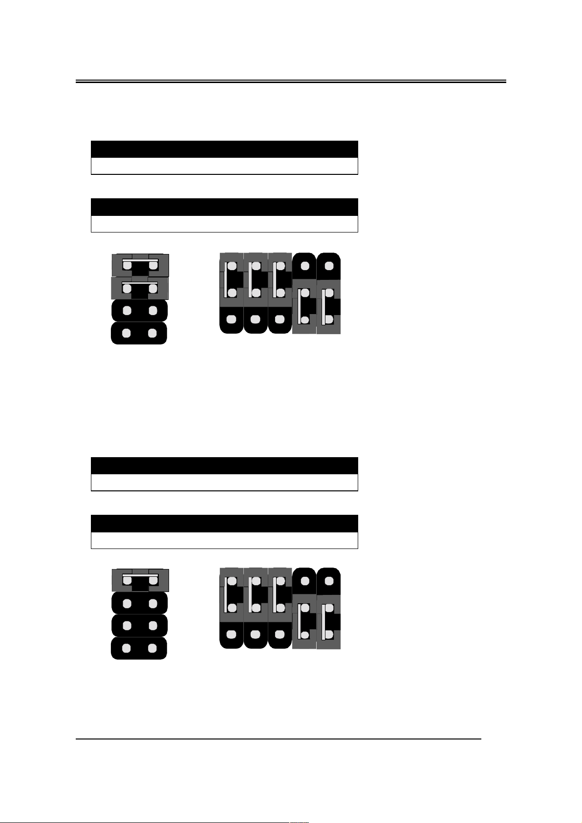
3. 300MHz (SDRAM Frequency is 66.6MHz)
JFREQ1
1-2 3-4 5-6 7-8
Open Short Open Short
JCK1~JCK4 (J3 :1-2 is default for IO Queue Depth)
JCK1 JCK2 JCK3 JCK4
1-2 1-2 1-2 2-3
6
4
JFREQ1
78
5
3
12
1
2
3
J3
JCK1
JCK2
JCK3
JCK4
4. 333MHz (SDRAM Frequency is 66.6MHz)
JFREQ1
1-2 3-4 5-6 7-8
Open Open Short Short
JCK1~JCK4 (J3 :1-2 is default for IO Queue Depth)
JCK1 JCK2 JCK3 JCK4
1-2 1-2 1-2 2-3
6
4
JFREQ1
78
5
1
2
3
3
12
J3
JCK1
JCK2
JCK3
JCK4
12
Page 16

B782/B783
5. 366MHz (SDRAM Frequency is 66.6MHz)
JFREQ1
1-2 3-4 5-6 7-8
Short Open Open Open
JCK1~JCK4 (J3 :1-2 is default for IO Queue Depth)
JCK1 JCK2 JCK3 JCK4
1-2 1-2 1-2 2-3
6
4
JFREQ1
78
5
3
12
1
2
3
J3
JCK2
JCK1
JCK3
JCK4
CPU Bus Speed – 100MHz part (SDRAM Frequency is 66.6MHz)
1. 350MHz
JFREQ1
1-2 3-4 5-6 7-8
Short Open Open Short
JCK1~JCK4 (J3 :1-2 is default for IO Queue Depth)
JCK1 JCK2 JCK3 JCK4
1-2 1-2 2-3 2-3
6
4
JFREQ1
78
5
3
12
1
2
3
J3
JCK1
13
JCK2
JCK3
JCK4
Page 17

B782/B783
2. 400MHz
JFREQ1
1-2 3-4 5-6 7-8
Open Short Short Short
JCK1~JCK4 (J3 :1-2 is default for IO Queue Depth)
JCK1 JCK2 JCK3 JCK4
1-2 1-2 2-3 2-3
6
4
JFREQ1
78
5
3
12
1
2
3
J3
JCK1
JCK2
JCK3
JCK4
3. 450MHz
JFREQ1
1-2 3-4 5-6 7-8
Open Short Open Short
JCK1~JCK4 (J3 :1-2 is default for IO Queue Depth)
JCK1 JCK2 JCK3 JCK4
1-2 1-2 2-3 2-3
6
4
JFREQ1
78
5
3
12
1
2
3
J3
JCK1
JCK2
JCK3
JCK4
14
Page 18
B782/B783
4. 500MHz
JFREQ1
1-2 3-4 5-6 7-8
Open Open Short Short
JCK1~JCK4 (J3 :1-2 is default for IO Queue Depth)
JCK1 JCK2 JCK3 JCK4
1-2 1-2 2-3 2-3
6
4
JFREQ1
78
5
3
12
1
2
3
J3
JCK1
JCK2
JCK3
JCK4
5. 550MHz
JFREQ1
1-2 3-4 5-6 7-8
Open Open Open Short
JCK1~JCK4 (J3 :1-2 is default for IO Queue Depth)
JCK1 JCK2 JCK3 JCK4
1-2 1-2 2-3 2-3
6
4
JFREQ1
78
5
3
12
1
2
3
J3
JCK1
JCK2
JCK3
JCK4
15
Page 19

B782/B783
CPU Bus Speed – 100MHz part (SDRAM Frequency is 100MHz)
1. 350MHz
JFREQ1
1-2 3-4 5-6 7-8
Short Open Open Short
JCK1~JCK4 (J3 :1-2 is default for IO Queue Depth)
JCK1 JCK2 JCK3 JCK4
1-2 1-2 2-3 1-2
6
4
JFREQ1
78
5
3
12
1
2
3
J3
JCK1
JCK2
JCK3
JCK4
2. 400MHz
JFREQ1
1-2 3-4 5-6 7-8
Open Short Short Short
JCK1~JCK4 (J3 :1-2 is default for IO Queue Depth)
JCK1 JCK2 JCK3 JCK4
1-2 1-2 2-3 1-2
6
4
JFREQ1
78
5
3
12
1
2
3
J3
JCK2
JCK1
JCK3
JCK4
16
Page 20

B782/B783
3. 450MHz
JFREQ1
1-2 3-4 5-6 7-8
Open Short Open Short
JCK1~JCK4 (J3 :1-2 is default for IO Queue Depth)
JCK1 JCK2 JCK3 JCK4
1-2 1-2 2-3 1-2
6
4
JFREQ1
78
5
3
12
1
2
3
J3
JCK1
JCK2
JCK3
JCK4
4. 500MHz
JFREQ1
1-2 3-4 5-6 7-8
Open Open Short Short
JCK1~JCK4 (J3 :1-2 is default for IO Queue Depth)
JCK1 JCK2 JCK3 JCK4
1-2 1-2 2-3 1-2
6
4
JFREQ1
78
5
3
12
1
2
3
J3
JCK2
JCK1
JCK3
JCK4
17
Page 21

B782/B783
5. 550MHz
JFREQ1
1-2 3-4 5-6 7-8
Open Open Open Short
JCK1~JCK4 (J3 :1-2 is default for IO Queue Depth)
JCK1 JCK2 JCK3 JCK4
1-2 1-2 2-3 1-2
78
6
4
5
3
12
JFREQ1
FAN CONNECTOR
JFAN 1
1
2
3
J3
JCK2
JCK1
JCK3
JCK4
1
GND
2
+12V
3
NC
18
Page 22

B782/B783
MEMORY INSTALLATION
No jumper setting is necessary for DRAM setting, BIOS will check
DRAM type and size automatically. B782 motherboard contains 3 by
168-pin DIMM sockets(DIMM1,DIMM2,DIMM3). B782 motherboard has
table-free ( or auto-bank ) feature and user can install DIMM into any
bank. The three DIMMs Sockets for system memory expansion from
8MB to 384 MB. Each bank provides 64-bit wide data path.
NOTE: Samples of System Memory Combinations Options
DIMM1 DIMM2 DIMM3 TOTAL
8MB --- --- 8MBytes
--- 8MB --- 8MBytes
--- --- 8MB 8MBytes
8MB 8MB --- 16MBytes
--- 8MB 8MB 16MBytes
8MB --- 8MB 16MBytes
16MB --- --- 16MBytes
--- 16MB --- 16MBytes
--- --- 16MB 16MBytes
8MB 8MB 8MB 24MBytes
16MB 8MB --- 24MBytes
16MB --- 16MB 32MBytes
16MB 16MB --- 32MBytes
--- --- 32MB 32MBytes
--- 32MB --- 32MBytes
32MB --- --- 32MBytes
8MB 16MB 16MB 40MBytes
32MB 32MB --- 64MBytes
--- 32MB 32MB 64MBytes
64MB --- --- 64MBytes
64MB 64MB --- 128MBytes
64MB 64MB --- 128MBytes
: : : :
: : : :
128MB 128MB 128MB 384MBytes
19
Page 23

B782/B783
Chapter 3
AWARD BIOS SETUP
Award BIOS ROM has a built-in Setup program that allows users to
modify the basic system configuration. This type information is stored in
battery-backed RAM so that it retains the Setup information when the power is
turned off.
ENTERING SETUP
Power on the computer and press <Del> immediately will allow you to
enter Setup. The other way to enter Setup is to power on the computer , when
the below message appears briefly at the bottom of the screen during the POST
(Power On Self Test), press <Del> key or simultaneously press <Ctrl>, <Alt>,
and <Esc> keys.
TO ENTER SETUP BEFORE BOOT PRESS CTRL-ALT-ESC OR
DEL KEY
If the message disappears before you respond and you still wish to enter
Setup, restart the system to try again by turning it OFF then ON or pressing the
"RESET" button on the system case. You may also restart by simultaneously
press <Ctrl>, <Alt> and <Del> keys. If you do not press the keys at the correct
time and the system does not boot , an error message will be displayed and you
will again be asked to,
PRESS F1 TO CONTINUE, CTRL-ALT-ESC OR DEL TO ENTER
SETUP
Control Keys
Up Arrow Move to previous item
Down Arrow Move to next item
Left Arrow Move to the item in the left hand
20
Page 24

B782/B783
Right Arrow Move to the item in the right hand
Esc Key Main Menu Quit and not to save changes to
CMOS
Status Page setup menu and Option Page
Setup Menu Exit current page and return to
Main Menu
PgUp Key Increase the numeric value or make changes
PgDn Key Decrease the numeric value or make changes
F1 Key General help, only for Status Page Setup
Menu and Option Setup
Menu
F2 Key Change color from total 16 colors
F3 Key Calendar, only for Status Page Setup Menu
F4 Key Reserved
F5 Key Restore the previous CMOS value from
BIOS, only for Option
Page Setup Menu
F6 Key Load the default CMOS value from BIOS
default table, only for
Option Page Setup Menu
F7 Key Load the default
F8 Key Reserved
F9 Key Reserved
F10 Key Save all the CMOS changes, only for Main
Menu
Getting Help
Main Menu
The on-line description of the highlighted setup function is displayed at the
bottom of the screen.
Status Page Setup Menu/Option Page Setup Menu
Press F1 to pop up a small help window that describes the appropriate keys
to use and the possible selections for the highlighted item. To exit the Help
Window press <Esc>.
21
Page 25

B782/B783
The Main Menu
Once you enter Award BIOS CMOS Setup Utility, the Main Menu will
appear on the Screen.. Use arrow keys to select among the items and press to
accept or enter the sub-menu.
ROM PC/ISA BIOS (2A6LFPN9)
CMOS SETUP UTILITY
AWARD SOFTWARE, INC.
STANDARD CMOS SETUP
BIOS FEATURE SETUP
CHIPSET FEATURES SETUP
POWER MANAGEMENT SETUP
PNP/PCI CONFIGURATION
LOAD BIOS DEFAULTS
LOAD SETUP DEFAULTS
Esc : Quit ←↑↓→ : Select Item
F10 : Save & Exit Setup (Shift) F2 : Change Color
Onboard I/O, IRQ, DMA Assignment….
Standard CMOS Setup
This setup page includes all the items in a standard compatible BIOS.
INTEGRATED PERIPHERALS
SUPERVISOR PASSWORD
USER PASSWORD
IDE HDD AUTO DETECTION
HDD LOW LEVEL FORMAT
SAVE & EXIT SETUP
EXIT WITHOUT SAVING
BIOS Features Setup
This setup page includes all the items of Award special enhanced features.
Chipset Features Setup
This setup page includes all the items of chipset special features.
Power Management Setup
22
Page 26

B782/B783
This menu provides functions for Green products by allowing users to set the
timeout value for monitor and HDD.
PNP / PCI CONFIGURATION SETUP
This menu allows the user to modify PNP / PCI configuration function.
Load BIOS Defaults
BIOS defaults indicates the most appropriate value of the system parameter
which the system would be in minimum performance.
Load Setup Defaults
Chipset defaults indicates the values required by the system for the maximum
performance.
INTEGRATED PERIPHERALS
This section page includes all the items of IDE hard drive and Programmed
Input / Output features.
Supervisor / User Password Setting
Change, set, or disable password. It allows you to limit access to the system
and Setup, or just to setup.
IDE HDD Auto Detection
Automatically configure hard disk parameters.
HDD Low Level Format
If supported by your system, this provides a hard disk low level format utility.
Save & Exit Setup
Save CMOS value changes to CMOS and exit setup.
Exit Without Saving
Abandon all CMOS value changes and exit setup.
23
Page 27

B782/B783
ON NOW FUNCTION
User can select the way to power on system from BIOS Setup. Choose “
Integrated Peripheral “ item , user can setup “ POWER ON FUNCTION”
1. BUTTON ONLY: Power on by power button only.
2. PASSORD: Select “KB Power on Password” then enter. Key in password
and save CMOS SETUP. Then user can power on system by Key-in
Password.
3. HOT KEY: Select “HOT KEY Function” ,”HOT KEY POWER ON “
4. Mouse Left: Power on by double click mouse left button.
5. Mouse Right : Power on by double click mouse left button.
Standard CMOS Setup
The item in Standard CMOS Setup Menu are divided into several
categories. Each category includes no, one or more than one setup items. Use
the arrow keys to highlight the item and then use the <PgUp> or <PgDn> keys
to select the value you want in each item.
˥ˢˠʳˣ˖˜˂˜˦˔ʳ˕˜ˢ˦ʳʻ˅˔ˉ˟˙ˣˡˌʼ
˦˧˔ˡ˗˔˥˗ʳ˖ˠˢ˦ʳ˦˘˧˨ˣ
˔˪˔˥˗ʳ˦ˢ˙˧˪˔˥˘ʿʳ˜ˡ˖ˁ
˗˴˸ʳʻˍ˷˷ˍʼʳˍʳ˪˸˷ʿʳ˗˸˶ʳ˅ˆʳ˄ˌˌˋ
˧˼˸ʳʻ˻˻ˍˍʼʳˍʳ˄ˊʳˍʳʳ˃ʳˍʳ˄ˆ
˛˔˥˗ʳ˗˜˦˞˦
ˣ˼˴ʳˠ˴˸ʳʳʳʳʳʳʳʳ
ˣ˼˴ʳ˦˿˴˸ʳʳʳʳʳʳʳʳʳʳʳ
˦˸˶˷˴ʳˠ˴˸
˦˸˶˷˴ʳ˦˿˴˸
˗˼˸ʳ˔ʳʳʳˍʳ˄ˁˇˇˠʿʳˆˁˈʳ˼ˁ
˗˼˸ʳ˕ʳʳʳˍʳˡ˸
˩˼˷˸ʳʳʳʳˍʳ˘˚˔˂˩˚˔
˛˴˿ʳˢʳˍʳ˔˿˿ʿʳ˕ʳ˞˸˵˴˷
˘˦˖ʳʳʳˍʳʳˤ˼
˙˄ʳʳʳʳʳˍʳʳ˛˸˿
˧ˬˣ˘ ˦˜˭˘ ˖ˬ˟˦ ˛˘˔˗ ˣ˥˘˖ˢˠˣ ˟˔ˡ˗˭ ˦˘˖˧ˢ˥ ˠˢ˗˘
˃
ˍ
˃
ˍ
ˍ
˃
ˍ
˃
˃
˃
˃
˃
˃
˃
˃
˃
˃
˃
˃
˃
˃
˃
˃
˃
ʳʳʳʳʳʳʳʳʳʳʳʳʳʳʳʳʳʳʳˍʳ˦˸˿˸˶ʳ˜˸ʳʳʳʳʳʳʳʳʳʳʳʳʳʳʳˣ˨˂ˣ˗˂ʾ˂ˀˍˠ˷˼˹
ʻ˦˻˼˹ʼʳ˙˅ʳʳʳˍʳ˖˻˴˺˸ʳ˖˿
˃
˃
˃
˃
ʳʳʳʳʳʳ˕˴˸ʳˠ˸ʳʳˍʳʳʳʳˉˇ˃˞
˘˸˷˸˷ʳˠ˸ʳˍʳʳˊ˄ˉˋ˞
ˢ˻˸ʳˠ˸ʳʳʳʳʳʳʳˍʳʳʳʳˆˋˇ˞
˧˴˿ʳʳʳˠ˸ʳʳʳʳʳʳˍʳʳʳˋ˄ˌ˅˞ʳʳʳʳʳʳʳʳʳʳʳ
˃
˃
˃
˃
ˡˢ˥ˠ˔˟
ˡˢ˥ˠ˔˟
ˡˢ˥ˠ˔˟
ˡˢ˥ˠ˔˟
24
Page 28

B782/B783
BIOS Features Setup
ROM PCI/ISA BIOS (2A6LFPN9)
BIOS FEATURE SETUP
AWARD SOFTWARE, INC
Anti-Virus Protection : Enabled Video BIOS Shadow
CPU Internal Cache : Enabled C8000-CBFFF Shadow
External Cache : Enabled CC000-CFFFF Shadow
CPU L2 Cache ECC Checking : Enabled D0000-D3FFF Shadow
Quick Power On Self Test : Enabled D4000-D7FFF Shadow
Boot Sequence : A, C ,SCSI D8000-DBFFF Shadow
Swap Floppy Drive : Disabled DC000-DFFFF Shadow
Boot Up Floppy Seek : Disabled
Boot Up NumLock Status : On
Gate A20 Option : Fast
Memory Parity/ECC Check : Enabled
Typematic Rate Setting : Disabled
Typematic Rate (Chars/Sec) : 6
Typematic Delay (Msec) : 250
Security Option : Setup
PCI/VGA Palette Snoop : Disabled
OS Select For DRAM > 64MB : Non-OS2 F1 : Help PU/PD/+/- : Modify
HDD S.M.A.R.T. capability : Disabled F5 : Old Values (Shift) F2 : Color
Report No FDD For WIN95 : No F6 : Load BIOS Default
Esc : Quit ↑↓→← : Selection Item
F7 : Load Setup Default
: Enabled
: Disabled
: Disabled
: Disabled
: Disabled
: Disabled
: Disabled
Virus Warning
This category flashes on the screen. During and after system boots up, any
attempt to write to the boot sector or partition table of the hard disk drive will
halt the system and the following error message will appear, in the mean time ,
you can run anti-virus programs to locate the problem.
!WARNING!
Disk boot sector is to be modified
Type "Y" to accept write or "N" to abort write
Award Software, Inc.
25
Page 29

B782/B783
Enabled Activate automatically when the system boots up causing a
warning message to appear when anything attempts to access
the boot sector or hard disk partition table.
Disabled No warning message to appear when anything attempt to access
the boot sector or hard disk partition table.
CPU Internal Cache/External Cache
These two categories speed up memory access. However, it depends on
CPU/chipset design. The default value is Enabled.
Enabled: Enabled cache
Disabled: Disabled cache
Quick Power On Self Test
This category speeds up Power On Self Test (POST) after you power on the
computer. If it is set to Enable, BIOS will shorten or skip some check items
during POST.
Enabled: Enable quick POST
Disabled: Normal POST
Boot Sequence
This category determines which drive computer searches first for the hard disk
operation system (i.e., DOS).
A, C,SCSI: System will first search for floppy disk drive then second
search hard disk driver, then SCSI driver.
26
Page 30

B782/B783
C,A,SCSI/ D,A,SCSI/ E,A,SCSI/ F,A,SCSI:
System will first search for IDE hard disk driver ( C: D: or E: or
F:) then second search floppy disk driver then SCSI hard disk
driver.
SCSI,A,C: System will first search SCSI hard disk driver then second
search for floppy disk driver then IDE hard disk driver.
CDROM,C,A:
System will first search for the CDROM driver ( If the CDROM
has a bootable CD title.)and second search hard disk driver then
floppy disk driver .
C,CDROM,A:
System will first search for the hard disk driver and second
search for CDROM driver ( If the CDROM has a bootable CD
title,) then search floppy disk driver.
LS120,C: System will first search LS120 disk driver and second search
for IDE hard disk driver.
Swap Floppy Drive
Users can enable this item so that the BIOS will see the hardware "Drive A:" as
"Drive B:", and hardware "Drive B:" as "Drive A:".
Boot Up Floppy Seek
During POST, BIOS will determine if the Floppy disk drive installed is 40 or
80 tracks. 360 K type is 40 tracks while 720K, 1.2M and 1.44M drive type as
they are all 80 tracks.
Enabled: BIOS searches for floppy disk drive to determine if it is 40 or 80
tracks. Note that BIOS can not tell from 720K, 1.2M or 1.44M
drive type as they are all 80 tracks.
Disabled: BIOS will not search for the type of floppy disk drive by track
number. Note that there will not be any warning message if the
drive installed is 360K.
27
Page 31

B782/B783
Boot Up NumLock Status
The default value is On.
On: Keypad is number keys
Off: Keypad is arrow keys
Boot Up System Speed
It selects the default system speed - the speed that the system will run at
immediately after power up.
High: Set the speed to high
Low: Set the speed to low
Gate A20 Option
The Gate A20 Option default setting is fast.”. This is the optimum setting for
this motherboard.
Typematic Rate Setting
This determines the typematic rate.
Enabled: Enable typematic rate
Disabled: Disable typematic rate
Typematic Rate (Chars/Sec)
6 : 6 characters per second
8 : 8 characters per second
10 : 10 characters per second
28
Page 32

B782/B783
12 : 12 characters per second
15 : 15 characters per second
20 : 20 characters per second
24 : 24 characters per second
30 : 30 characters per second
Typematic Delay (Msec)
When holding the a key, the time between the first and second character will be
displayed.
250 : 250 msec
500 : 500 msec
750 : 750 msec
1000 : 1000 msec
Security Option
This category allows you to limit access to the system and Setup, or just to
Setup.
System: The system will not boot and access to Setup will be denied if
the correct password is not entered at the prompt.
Setup: The system will boot, but access to Setup will be denied if the
correct password is not entered at the prompt.
Note: To disable security, select PASSWORD SETTING at Main Menu and
then you will be asked to enter password. Do not type anything and just press
<Enter>, it will disable security. Once the security is disabled, the system will
boot and you can enter Setup freely.
29
Page 33

B782/B783
Video BIOS Shadow
It determines whether video BIOS will be copied to RAM, however, it is
optional from chipset design. Video shadow will increase the video speed.
Enabled: Video shadow is enabled
Disabled: Video shadow is disabled
C8000-CBFFF Shadow/DC000-DFFFF Shadow
These categories determine whether optional ROM will be copied to RAM by
16K byte.
Enabled: Optional shadow is enabled
Disabled: Optional shadow is disabled
30
Page 34

B782/B783
Chipset Features Setup
ROM PCI/ISA BIOS (2A6LFPN9)
CHIPSET FEATURE SETUP
AWARD AOFTWARE, INC.
Bank 0/1 DRAM Timing : SDRAM 10ns Auto Detect DIMM/PCI Clk
Bank 2/3 DRAM Timing : SDRAM 10ns Spread Spectrum Modulated : Disabled
Bank 4/5 DRAM Timing : SDRAM 10ns
SDRAM Cycle Length : 3
Memory Hole At 15Nb Addr. : Disabled
Read Around write : Disabled
Concurrent PCI/Host
Video RAM Cacheable : Disabled
AGP Aperture Size : 64M
AGP-2X Mode : Disabled
Disabled
:
Esc : Quit ↑↓→← : Selection Item
F1 : Help PU/PD/+/- : Modify
F5 : Old Values (Shift) F2 : Color
F6 : Load BIOS Default
F7 : Load Setup Default
: Enabled
This setup menu is optimized for this mainboard by your computer vendor.
Unless you are a qualified engineer & know the items, functions you are going
to modify. We do not recommend you to change the default setting.
31
Page 35

B782/B783
Power Management
ROM PCI/ISA BIOS (2A6LFPN9)
POWER MANAGEMENT SETUP
AWARD SOFTWARE, INC.
ACPI function : Disabled Primary INTR : ON
Power Management : User Define IRQ3 (COM 2) : Primary
PM Control by APM : Yes IRQ4 (COM 1) : Primary
.Video Off Option : Suspend IRQ5 (LPT 2) : Primary
Video Off Method : V/H SYNC+Blank IRQ6 (Floppy Disk) : Primary
MODEM Use IRQ : 3 IRQ7 (LPT 1) : Primary
Soft-Off by PWRBTN : Instant-Off IRQ8 (RTC Alarm) : Disabled
HDD Power Down : Disabled IRQ9 (IRQ2 Redir) : Secondary
Doze Mode : Disabled IRQ10 (Reserved) : Secondary
Suspend Mode : Disabled IRQ11 (Reserved) : Secondary
ϠϠΓPM EventsΓϠϠ
VGA : OFF IRQ13 (Coprocessor) : Primary
LPP & COM : LPT/COM IRQ14 (Hard Disk) : Primary
HDD & FDD : ON IRQ15 (Reserved) : Disabled
DMA/master : OFF
Modem Ring Resume : Disabled
RTC Alarm Resume : Disabled F1 : Help PU / PD / + / - : Modify
IRQ12 (PS/2 Mouse) : Primary
ESC: Quit ↑↓→←: Select Item
F5 : Old Values (Shift)F2 : Color
F6 : Load BIOS Defaults
F7 : Load Setup Defaults
This category determines the power consumption for the system after selecting
below items. Default value is Disabled. The following pages tell you the
options of each item & describe the meanings of each options.
32
Page 36

B782/B783
Item Options Descriptions
A. Power Management 1. Disable Global Power Management will be
disabled
2. User Define Users can configure their own power
management
3. Min Saving Pre-defined timer values are used such
that all timers are in their MAX value
4. Max Saving Pre-defined timer values are used such
that all timers MIN value
Item Options Descriptions
B. PM Control by APM 1. No System BIOS will ignore APM when
power managing the system
2. Yes System BIOS will wait for APM’ s
prompt before it enter any PM mode
e.g. DOZE, STANDBY or SUSPEND
Note: If APM is installed, & if there is a task running,
even the timer is time out, the APM will not prompt the
BIOS to put the system into any power saving mode!
Note: − if APM is not installed, this option has no effect
To make the APM function work, users have to install
power.exe (supported by MS-DOS 5.0 or higher) in
Config.exe. To make the Windows 3.1 work regularly, in
" Windows Setup", users have to set the
"Computer" item to " MS-DOS System with APM"
C. Video Off Option 1. Always On System BIOS will never turn
off the screen
2. Suspend −> Off
3. Susp, Stby − Off
Screen off when system is in
SUSPEND mode
Screen off when system is in
STANDBY or SUSPEND
mode
33
Page 37

B782/B783
4. All Modes −> Off
D. Video 1. Blank Screen The system BIOS will only
2. V/H SYN
C+Blank
Item Options Descriptions
D. Video 3. DPMS This function is enabled for
E. HDD Power Down 1. Disable HDD’ s motor will not off
(#) Remark 2 2. 1. Min
2. Min
3. Min
4. Min
5. Min
6. Min
7. Min
8. Min
9. Min
10. Min
11. Min
12. Min
13. Min
14. Min
15. Min
3. When Suspend BIOS will turn the HDD’ s
Note:
− (2) & (3) can’ t be selected at the same time
− When HDD is in power saving mode, any access
to the HDD will wake the HDD up
Screen off when system is in
DOZE, STANDBY or
SUSPEND mode
blanks off the screen when
disabling video
In addition to (1), BIOS will
also turn off the V-SYNC &
H-SYNC signals form VGA
cards to monitor
only the VGA card
supporting DPM
Defines the continuous HDD
idle time before the HDD
entering power saving mode
(motor off)
motor off when system is in
SUSPEND mode
34
Page 38

B782/B783
Item Options Descriptions
F. Doze Mode
(*) Remark 1
3 Standby Mode
(*) Remark 1
2. Disable System will never enter
DOZE mode
2. 10 Sec
10 Sec
20 Sec
30 Sec
40 Min
1 Min
3 Min
5 Min
10 Min
15 Min
20 Min
30 Min
40 Min
1 Hr
2 Hr
3 Hr
Note: Normally, STANDBY mode puts the system
into low speed or 8 MHz, screen may be
off depend on (E)
1. Disable System will never enter
3. 10 Sec
20 Sec
30 Sec
40 Sec
1 Min
3 Min
5 Min
10 Min
15 Min
20 Min
30 Min
40 Min
1 Hr
2 Hr
3 Hr
Defines the continuous idle
time before the system
entering DOZE mode.
If any item defined in (J) is
enabled & active, DOZE
timer will be reloaded.
STANDBY mode
Defines the continuous idle
time before the system
entering STANDBY mode.
If any item defined in (J) is
enabled & active,
STANDBY timer will be
reloaded
35
Page 39

B782/B783
Normally, STANDBY mode puts the system into low
speed or 8, screen may be off depend on (E)
Item Options Descriptions
H. Suspend Mode
(*) Remark 1
I. PCI Master Activity
COM Ports Activity
LPT Ports Activity
HDD Ports Activity
DMA Ports Activity
VGA Activity
IRQ3 (COM 2)
IRQ4 (COM 1)
IRQ5 (LPT 2)
IRQ6 (Floppy Disk)
IRQ7 (LPT 1)
IRQ8 (RTC Alarm)
IRQ9 (IRQ2 Redir)
IRQ10 (Reserved)
IRQ11 (Reserved)
IRQ12 (PS/2 Mouse)
IRQ13 (Coprocessor)
1. Disable System will never enter
SUSPEND mode
2. 10 Sec
20 Sec
30 Sec
40 Sec
1 Min
3 Min
5 Min
10 Min
15 Min
20 Min
30 Min
40 Min
1 Hr
2 Hr
3 Hr
Note: Normally, SUSPEND mode puts the system
into low speed or 8 MHz, clock is stopped, screen
may be off depend on (E)
1. Disable The specified event’ s
2. Enable The specified event’ s
Defines the continuous idle
time before the system
entering SUSPEND mode.
if any item defined in (J) is
enabled & active, SUSPEND
timer will be reloaded
activity will not affect the
PM timers
activity causes the PM
Timers to be reloaded.
i.e. the Power
ManagementUnit(PMU)
monitors the specified
activities as PM events
36
Page 40

B782/B783
IRQ14 (Hard Disk)
IRQ15 (Reserved)
* Remark 1: All items mark with (*) in this menu, will be loaded with
predefined values as long as the item "Power Management" is not configured to
"User Defined"
These items are:
Item "System Doze" , "System Standby" & "System Suspend"
# Remark 2: Although the item "HDD Power Down" is not controlled by
item "Power Management" in terms of timer value, the HDD (s) will not power
down if the global power management is disabled!
37
Page 41

B782/B783
PNP / PCI Configuration Setup
ROM PCI/ISA BIOS(2A6LFPN9)
PNP/PCI CONFIGURATION
AWARD SOFTWARE, INC.
PNP OS Installed : No CPU to PCI Write Buffer : Enabled
Resources Contorlled By : Manual PCI Dynamic Bursting : Enabled
Reset Configuration Data : Disabled PCI Master 0 WS Write : Enabled
PCI Delay Transaction : Enabled
IRQ-3 assigned to : PCI/ISA PnP PCI#2 Access #1 Retry : Disabled
IRQ-4 assigned to : PCI/ISA PnP AGP Master 1 WS Write : Enabled
IRQ-5 assigned to : PCI/ISA PnP AGP Master 1 WS Read : Disabled
IRQ-7 assigned to : PCI/ISA PnP
IRQ-9 assigned to : PCI/ISA PnP PCI IRQ Actived By : Level
IRQ-10 assigned to : PCI/ISA PnP Assign IRQ For USB : Enabled
IRQ-11 assigned to : PCI/ISA PnP Assign IRQ For VGA : Enabled
IRQ-12 assigned to : PCI/ISA PnP
IRQ-14 assigned to : PCI/ISA PnP
IRQ-15 assigned to : PCI/ISA PnP
DMA-0 assigned to : PCI/ISA PnP
DMA- 1 assigned to : PCI/ISA PnP
DMA- 3 assigned to : PCI/ISA PnP F1 : Help PU / PD / + / - : Modify
DMA- 5 assigned to : PCI/ISA PnP F5 : Old Values (Shift)F2 : Color
DMA- 6 assigned to : PCI/ISA PnP F6 : Load BIOS Defaults
DMA- 7 assigned to : PCI/ISA PnP F7 : Load Setup Defaults
ESC: Quit ↑↓→←: Select Item
The following pages tell you the options of each item & describe the meanings
of each options.
Item Options Descriptions
A. 1st Available IRQ
2nd Available IRQ
3rd Available IRQ
4th Available IRQ
3
4
5
7
The system BIOS will assign these 4
available IRQs to the found PCI devices
9
10
11
12
14
15
NA
38
Page 42

B782/B783
Item Options Descriptions
B. PCI IDE 2nd Channel Enable
Disable
C. PCI IDE IRQ Map To PCI-
AUTO
PCISLOT1
PCISLOT2
ISA
Enable/disable 2nd channel of PCI/IDE card.
It includes I/O port (170H~177H) and IRQ 15
assignment
PCI-AUTO
The BIOS will:
− scan for PCI IDE devices &
determine the location of the PCI
IDE device
PCI-SLOT1
PCI-SLOT2
− assign IRQ 14 for primary IDE INT# IRQ
15 for secondary IDE INT# for the specified
slot
ISA
− The BIOS will not assign any IRQs even if
PCI IDE card is found!
Because some IDE cards connect the IRQ
14 & 15 directly from ISA slot thru a cord.
(This cord is called Legacy Header)
To tell which INT# does the PCI IDE card is
using for its interrupts
F. Primary IDE INT#
Secondary IDE INT#
PCIAUTO
PCISLOT1
PCISLOT2
ISA
A
B
The other item are optimized by your computer vendor, please do not modify
them unless you know its function exactly.
39
Page 43

B782/B783
INTEGRATED PERIPHERALS
ROM PC/ISA BIOS(2A6LFPN9)
INTEGRATED PERIPHERALS
AWARD SOFTWARE, INC.
OnChip IDE Channe10 : Enabled RxD , TxD Active
OnChip IDE Channe11 : Enabled Onboard Parallel Port : 378/IRQ7
IDE Prefetch Mode : Enabled Onboard Parallel Mode
IDE HDD Block Mode : Enabled ELP Mode Use DMA
Primary Master PIO : Enabled Parallel Port EPP Type
Primary Slave PIO : Auto Onchip USB
Secondary Master PIO : Auto
Secondary Slave PIO : Auto
Primary Master UDMA : Auto
Primary Slave UDMA : Auto
Secondary Master UDMA : Auto
Secondary Slave UDMA : Auto
Init Display First : PCI Slot
Onboard FDD Controller
FDC Write Protect
Onboard Serial Port 2
Onboard Series Ports
UART 2 Mode
IR Function Duplex
: Enabled
: Disabled
: 3F8/IRQ4
: 2F8/IRQ3
: Standard
: Half
Esc : Quit ↑↓→← : Selection Item
F1 : Help PU/PD/+/- : Modify
F5 : Old Values (Shift) F2 : Color
F6 : Load BIOS Default
F7 : Load Setup Default
: Hi ,Hi
: ECP/EPP
: 3
: EPP 1.9
: Disabled
This setup menu is optimized for this motherboard by your computer vendor.
Unless you are a qualified engineer & know the items, function you are going to
modify. We do not recommend you to change the default setting.
40
Page 44

B782/B783
Load BIOS Default
When you access "Load BIOS Default", the following message appears:
Load BIOS Default (Y/N) ?N
The BIOS Default values are the "worst case" default, and are the most stable
values for the system. Use them if the system is performing erratically due to
hardware problems. To load the BIOS Default values, press <Y> then
<Enter>.
Load Setup Default
When you access "Load Setup Default", you are shown the following message:
Load Setup Default (Y/N) ?N
The Setup Default values represent the "best case" default, and should provided
optimum system performance. To load the Setup Default values, press <Y>
then <Enter>.
Supervisor / User Password Setting
When you select this function, the following message will appear at the center
of the screen to assist you in creating a password.
ENTER PASSWORD
Type the password, up to eight characters, and press <Enter>. The password
typed now will clear any previously entered password from CMOS memory.
You will be asked to confirm the password. Type the password again and press
<Enter>. You may also press <Esc> to abort the selection and not enter a
password.
If you select System at Security Option of BIOS Features Setup Menu, you will
be prompted for the password everytime the system is rebooted or anytime you
try to enter Setup. If you select Setup at Security Option of BIOS Features
Setup Menu, you will be prompted only when you try to enter Setup.
41
Page 45

B782/B783
IDE HDD Auto Detection
This feature allows you to check all the informations on your hard disk
formation. When you access "IDE HDD Auto Detection", the system executes
auto detection.
At the prompt, it represents all the informations on your HDD, and you are
asked:
Do you accept this drive C: (Y/N) ?
1 If you accept the test result, press [Y] then [Enter] and the result is
saved, then the system continues to detect another HDD.
2 If not, press [N] then [enter] and the system continues to detect another
HDD.
42
 Loading...