

pro comp K2079BMX, K2079B, 56713B, K2079BP, 56713BP Installation Manual
...
PRO COMP SUSPENSION
K2079B/K2079BMX/K2079BP
56713B/56713BMX/56713BP
2009 Dodge 1500 Mega Cab/ 2500 4X4 6” Coil
Spring Lift kit
This document contains very important information that includes warranty information and instructions for
resolving problems you may encounter. Please keep it in the vehicle as a permanent record.

56713B/K2079B
Box 1 of 3-PN # 56713B/56713BMX-1
Revised
2.19.15
Part # Description Qty. Illus. Page
DC601-1 PITMAN ARM 1 - 15-10995 BUMPSTOP 2 3 7
90-6029 HARDWARE PACK:
Brake Line
15-10966 3/8” PLASTIC HOSE CLAMPS 4 - 13-20447 #10 X 1/2" HWH ZINC 4 - -
90-2359 LOWER CONTROL ARM 2 4,5 8,9
90-2361 UPPER CONTROL ARM:
90-6273 HARDWARE PACK:
Lower Control Arm
15-10979 BUSHINGS LOWER ARM 8 4 8
90-2101 SLEEVE: 7/8" X .635" X 2.618" 4 4 8
90-6274 HARDWARE PACK:
Upper Control Arm
15-11187 BUSHINGS LOWER ARM 8 4 8
90-2114 SLEEVE: .75” X .095" X 2.360" 4 4 8
90-6024 HARDWARE PACK:
Sway Bar
70-0371501500 3/8” x 1 1/2” USS Gr. 5 Bolt 2 7 11
70-03725001500 3/8” x 2 1/2” USS Gr. 5 Bolt 2 7 11
72-03700100512 3/8” USS LOCKNUT 4 7 11
73-03700030 3/8” SAE FLAT WASHER 4 7 11
73-03700042 3/8” USS HARDENED FLAT WASHER 2 7 11
90-6312 HARDWARE PACK:
SWAY BAR LINK
45359 HOURGLASS BUSHING 4 7 11
P-843 SPACER PACK 2 7 11
61150 3/8" SLEEVE 2 7 11
90-2039 SWAY BAR ADAPTER SLEEVE 2 7 11
90-1010 SWAY BAR END LINK 2 7 11
90-2357 DODGE SWAY BAR END LINK 2 7 11
13-90330 U-BOLTS:
9/16" X 3.65" X 13.5"
20-65302 HARDWARE PACK:
U-BOLT
9/16" WASHERS 8 B 15
9/16" NUTS 8 B 15
95-300D 3" ALUMINUM BLOCK 2 B 15
51255 SHIM KIT 1 - 90-6327 HARDWARE PACK:
SHIM KIT
90-3081 BUMP STOP BRACKETS 4 A 14
90-6223 HARDWARE PACK: 1 - 90-6242 HARDWARE PACK: 1 - -
600026 3/4" BUSHING 2 - P-1036 SLEEVE 2 - -
2
1 - -
15 degree bend
2 4,5 8,9
1 - -
1 - -
1 - -
1 - -
4 B 15
1 - -
1 - -

56713B/K2079B
Revised
2.19.15
Part # Description Qty. Illus. Page
90-6430 HARDWARE PACK: 1 - -
71-140802001000 14mm- 2.0 X 80mm HEX BOLT Gr. 10.9 2 - .140CNUCZ 14mm- 2.0 STOVER NUT 2 - 73-01410930 14mm FLAT WASHER PLATED 4 - -
13-90328 U-BOLTS:
5/8”-18– X 4.125” X 13.875
20-65471 HARDWARE PACK:
U-BOLT
1 - -
5/8" WASHERS 8 B 15
5/8" NUTS 8 B 15
90-1539 FRONT BRAKE LINE EXTENSION BRACKET 2 - 90-6299 HARDWARE PACK:
Front Brake Lines
70-0311001800 5/16” X 1" HEX BOLT GR. 8 2 - -
72-0531100816 5/16” NYLOCK NUT 2 - 73-03100034 5/16” HARDENED FLAT WASHER 4 - -
90-6654 HARDWARE PACK:
Upper Control Arm Bolt
70-0565501800 9/16" X 5 1/2" Gr. 8 HEX BOLT 1 - 72-056100816 9/16" STOVER NUT 1 - 73-05600034 9/16" HARDENED FLAT WASHER Gr. 8 2 - -
96-5779 PITMAN ARM TORQUE TOOL 1 6 10
HERNON427 RED THREAD LOCKER 1 - 90-6748 HARDWARE PACK:
Lower Control Arm: 2010 Model
15-10978 BUSHING LOWER ARM 4 4 8
90-8083 SLEEVE 2 4 8
4 B 15
1 - -
1 - -
1 - -
Box 2 of 3 PN # 56716B-2
91-7658 TRACK BAR DROP BRACKET 1 11 14
90-6874 HARDWARE PACK:
Track Bar Drop Bracket
90-4460 TRACK BAR NUT 1 11 14
90-8233 CROSSMEMBER SLEEVE : 3/4” X 1 1/2” 1 11 14
90-8231 5/8” TRACK BAR DROP BOLT SPACER:
90-8232 5/8” TRACK BAR DROP BOLT SPACER:
61734 7/16” SPLIT- SLEEVE 1 11 14
90-7882 7/16” WASHER 2 11 14
HERNON427 THREAD LOCKER: RED 1 - -
90-6852 HARDWARE PACK:
Track bar Cam Bolt
90-4412 CAM BOLT 1 11 14
90-7663 CAM BOLT WASHER 1 11 14
73-06200838 5/8” GR. 8 AN FLAT WASHER PLATED 1 11 14
72-062200816 5/8"-18 SAE GR. 8 STOVER NUT 1 11 14
90-6875 HARDWARE PACK:
Track Bar Drop Bracket
70-0624501800 5/8” X 4 1/2 HEX BOLTGR 8 1 11 14
72-062100816 5/8” STOVER NUT GR. C 1 11 14
73-06200034 5/8” HARDENED FLAT WASHER 2 11 14
70-0502501800 1/2” X 2 1/2" HEX BOLT GR 8 1 11 14
73-05000034 1/2” HARDENED FLAT WASHER 1 11 14
70-0433001800 7/16” X 3" HEX BOLT GR 8 1 11 14
72-043100816 7/16” STOVER NUT GR. C 1 11 14
73-04300034 7/16” HARDENED FLAT WASHER 1 11 14
3
1 - -
1 11 14
Long
1 11 14
Short
1 - -
1 - -
56713B/K2079B
Box 3 of 3 PN # 56713B-3
Revised
2.19.15
Part # Description Qty. Illus. Page
929592 FRONT SHOCK ABSORBER 2 2,7 7,11
929543 REAR SHOCK ABSORBER 2 - -
OR Box 3 of 3 PN # 56713BMX-3
MX6158 FRONT SHOCK MX-6 SHOCK ABSORBER 2 2,7 7,11
MX6100 REAR SHOCK MX-6 SHOCK ABSORBER 2 - -
OR Box 3 of 3 PN # 56708BP-3
ZX2009 FRONT PRO RUNNER SHOCK 2 - ZX2001 REAR PRO RUNNER SHOCK 2 - -
FOLLOWING PARTS ARE USED IN CONJUNCTION WITH THIS KIT.
THEY ARE PACKAGED AND MUST BE ORDERED SEPARATELY.
COIL SPRINGS: 56160 (Diesel) For 56713 6” Coil Spring kit
COIL SPRINGS: 56170 (Gas) For 56713 6” Coil Spring kit
Transmission Brackets:
90-5143B Transmission Drop Bracket: 2009 (Gas) 1
90-5152B Transmission Drop Bracket: 2009-2011 (6.7L Diesel) 1
OPTIONAL EQUIPMENT:
56711 Long Arm Upgrade Kit
56120 Double Shock Hoop Kit
4

56713B/K2079B
Revised
2.19.15
Introduction:
This installation requires a professional mechanic!
We recommend that you have access to a factory service manual for your vehicle to assist in the disassembly and
reassembly of your vehicle. It contains a wealth of detailed information.
Prior to installation, carefully inspect the vehicle’s steering and driveline systems paying close attention to the tie
rod ends, wheel bearing preload, pitman and idler arm. Additionally, check steering-to-frame and suspension-toframe attaching points for stress cracks. The overall vehicle must be in excellent working condition. Repair or replace all worn or damaged parts!
Read the instructions carefully and study the illustrations before attempting installation! You may save yourself a lot
of extra work.
Check the parts and hardware against the parts list to assure that your kit is complete. Separating parts according
to the areas where they will be used and placing the hardware with the brackets before you begin will save installation time.
Check the special equipment list and ensure the availability of these tools.
Secure and properly block vehicle prior to beginning installation.
ALWAYS
Use caution when cutting is required under the vehicle. The factory undercoating is flammable. Take appropriate
precautions. Have a fire extinguisher close at hand.
Foot pound torque readings are listed on the Torque Specifications chart at the end of the instructions. These are to
be used unless specifically directed otherwise. Apply thread lock compound where specified.
Please note that while every effort is made to ensure that the installation of your Pro Comp lift kit
is a positive experience, variations in construction and assembly in the vehicle manufacturing
process will virtually ensure that some parts may seem difficult to install. Additionally, the current trend in manufacturing of vehicles results in a frame that is highly flexible and may shift
slightly on disassembly prior to installation. The use of pry bars and tapered punches for alignment is considered normal and usually does not indicate a faulty product. However, if you are uncertain about some aspect of the installation process, please feel free to call our tech support department at the number listed on the cover page. We do not recommend that you modify the Pro
Comp parts in any way as this will void any warranty expressed or implied by the Pro Comp Suspension company.
Disconnect the negative battery cable when working on the vehicle.
wear safety glasses when using power tools or working under the vehicle!
Front end and head light realignment is necessary!
Speedometer and ABS recalibration will be necessary if larger tires (10% more than stock diameter) are installed.
Tire and wheel choice is crucial in assuring proper fit, performance, and the safety of
your Pro Comp equipped vehicle. For this application, a wheel not to exceed 10” in width with a
minimum backspacing of 3.25” must be used. Additionally, a quality tire of radial design, not
exceeding 35” tall X 13.5” wide (for the 5” spacer kit) or 37 tall X 13.5” wide (for the 6” coil kit)
is recommended. Violation of these recommendations will not be endorsed as acceptable by Pro
Comp Suspension and will void any and all warranties either written or implied.
SPECIAL TOOLS
PLEASE REFER TO YOUR SERVICE MANUAL FOR MORE INFORMATION.
A SPECIAL REMOVAL TOOL IS REQUIRED FOR SAFE REMOVAL OF THE TIE RODS.
A SPECIAL REMOVAL TOOL IS REQUIRED FOR SAFE REMOVAL O F THE COIL SPRINGS.
THESE TOOL MAY BE PURCHASED AT YOUR LOCAL DEALER.
YOU MAY BE ABLE TO RENT ANY OF THESE TOOLS AT YOUR LOCAL PARTS STORE.
5
Front Installation
56713B/K2079B
Revised
2.19.15
1. Prior to installing this kit. With the vehicle
on the ground, measure the height of your
vehicle. This measurement can b e re corded from the center of the wheel,
straight up to the top of the inner fender
RF: LF:
LR: RR:
lip. Record the measurements below.
2. Ensure that your work space is of adequate size and the work surface is level.
Set the emergency brake. Place your floor
jack under the front axle and raise vehicle.
Place jack stands under the frame rails
behind the front wheel wells and lower the
frame onto the stands. Remove the jack
and place blocks both in front of and behind the rear wheels. Remove the
wheels.
3. Remove any skid plates or debris shields
from the bottom of the vehicle.
4. Unbolt both brake line brackets from the
frame and front axle brackets to allow for
free movement of the suspension components.
5. Unbolt sway bar from end links.
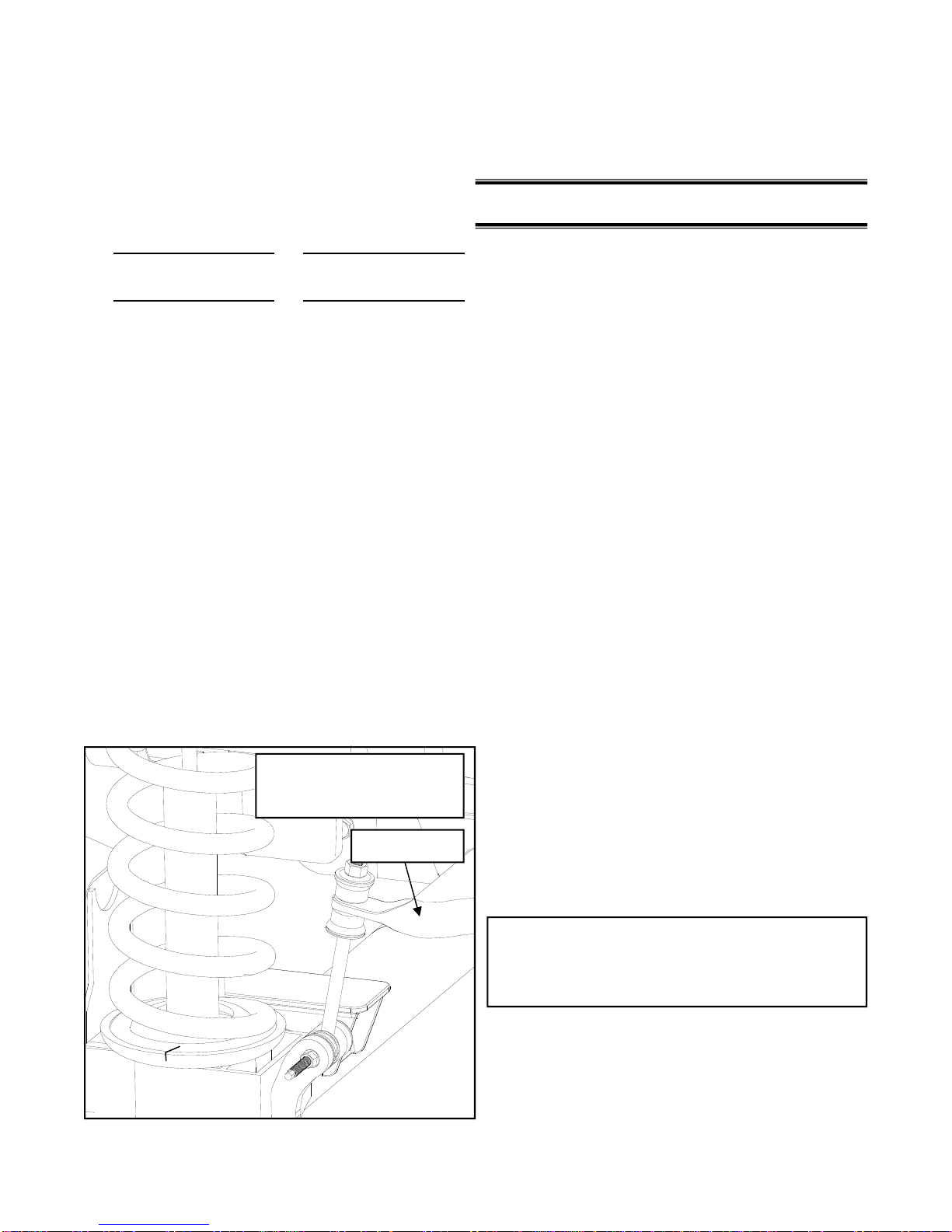
ILLUSTRATION 1
Factory set-up
SWAY BAR
6. Unbolt and remove the front track bar from
the vehicle. Save the OE bolts and hardware for reuse
Work on one side of the vehicle at a time.
7. Raise a jack under the coil springs to support the axle.
8. Compress coil spring with coil spring compressor tool.
9. Locate the top shock mount in the engine
compartment. Remove the nut, retainer
and grommet from the shock. See ILLUS-
TRATION 2.
10. Unbolt the shock absorber from the lower
mount bracket on the axle. Remove the
shock through the engine compartment.
11. Carefully lower the floor jack until coil
spring is free from the upper spring
pocket. Remove the coil spring.
12. Remove and set aside the upper rubber
isolator pad for the coil.
13. Repeat on other side of the vehicle.
14. Locate the front rubber bump stops,
mounted on the frame near the coils. Remove the bump stop from it’s pocket using
a pair of pliers. A back and forth action
will assist in working it out.
15. Place the new bump stops, PN 15-10995,
in existing bump stop pockets, as shown
in ILLUSTRATION 3. By using leverage
against the bottom of the bump stops,
force the bump stop into place (detergent
soap may help if the fit is tight).
Complete control arm replacement on
one side of the vehicle before removing
the control arm from the other side.
16. On the bottom of the lower control arm.
Mark the location of the index mark on the
adjustment cam-bolt and bracket, remove
the cam-bolt, washer and nut.
6
 Loading...