

Procomp BS61M Series Manual

BS61Mseries
~0~
Safety and Regulatory Information
Notice for the USA
FCC Part 15: This equipment has been tested and found to comply with
the limits for a class B digital device, pursuant to Part 15 of the FCC Rules.
These limits are designed to provide reasonable protection against harmful
interference in a residential installation. This equipment generates, uses, and
can radiate radio frequency energy and, if not installed and used in
accordance with the instructions, may cause harmful interference to radio
communications. However, this notice is not a guarantee that interference
will not occur in a particular installation.
CAUTION: To comply with the limits for the class B device, pursuant
to Part 15 of the FCC Rules, this device must be installed in computer
equipment certified to comply with the Class B limits.
All cables used to connect the computer and peripherals must be shielded and
grounded. Operation with non-certified computers or non-shielded cables
may result in interference to radio or television reception.
Any changes or modifications not expressly approved by the grantee of
this device could void the user’ s authority to operate the device.
COPYRIGHT: This publication, including all photographs, illustrations
and software, is protected under international copyright laws, with all rights
reserved. Neither this manual, nor any of the material contained herein, may
be reproduced without the express written consent of the manufacturer.
DISCLAIMER: The information in this document is subject to change
without notice. The manufacture makes no representations or warranties with
respect to the contents hereof and specifically disclaims any implied
warranties of merchantability or fitness for any particular purpose.

BS61Mseries
~1~
TABLE OF CONTENTS
ch1. MOTHERBOARD FEATURE ..................................................... 2
1.1 ABOUT THE MANUAL...................................................... 3
1.2 DETERMINING YOUR BS61M
SERIES MODEL .................. 3
1.3 BS61M
SERIES SPECIFICATION......................................... 4
1.4 COLOR CODING FOR PC99 CONNECTORS................. 6
1.5 POWER OFF CONTROL SOFTWARE ............................ 8
1.6 PACKAGING CHECK LIST............................................... 9
ch2. Setup Guide.............................................................................. 10
2.1 MOTHERBOARD LAYOUT............................................. 10
2.2 CONNECTOR & JUMPER REFERENCE CHART ......... 11
2.3 THE SETUP STEPS........................................................ 12
2.3-1 JUMPER & CONNECTOR SETTING ................... 12
2.3-2 MEMORY INSTALLATION.................................... 23
2.3-3 HOW TO INSTALL THE CPU ............................... 26
2.3-4 INSTALLING THE MOTHERBOARD.................... 28
2.3-5 INSTALLING THE INTERFACE CARD ................ 29
2.3-6 INSTALLING ACCESSORY CABLES .................. 30
ch3. AWARD BIOS SETUP .............................................................. 32
3.1 THE MAIN MENU............................................................ 34
3.2 STANDARD CMOS SETUP............................................ 36
3.3 BIOS FEATURES SETUP............................................... 38
3.4 CHIPSET FEATURES SETUP........................................ 42
3.5 POWER MANAGEMENT ................................................ 46
3.6 PNP / PCI CONFIGURATION SETUP............................ 51
3.7 INTEGRATED PERIPHERALS ....................................... 53
3.8 SUPERVISOR PASSWORD & USER PASSWORD ...... 56
3.9 IDE HDD AUTO DETECTION OPTION.......................... 56
3.10 SAVE AND EXIT SETUP OPTION ............................... 57
3.11 EXIT WITHOUT SAVING OPTION ............................... 57
ch4. SOFTWARE SETUP ................................................................. 58
4.1 INSTALLING SIS 620 VGA DRIVER .............................. 58
4.2 INSTALLING THE IDE DRIVER...................................... 60
4.3 INSTALLING THE AUDIO DRIVER & AP ....................... 61

BS61Mseries
~2~
Congratulations on purchasing a BS61Mseries motherboard, which we
are certain will provide you with years of reliable and stable performance.
Motherboards in the BS61M
series are Micro-ATX boards that measure
244 mm by 210 mm and which use a 4-layer printed circuit board. Your
board features a PPGA370ZIF (Zero Insertion Force) processor socket that
can house any of Intel’s original generation processors and other compatible
CPU. What’s more, it’s now undergoing testing at Taiwan’s National
Software Testing Laboratories to ensure it’ s fully Y2K compliant.
Motherboards in the BS61M
series support system bus speeds of both
66MHz and 100MHz, which means you may use either inexpensive 66MHz
memory chips or high-performance 100MHz chips. You can also overclock
your system, as your motherboard supports CPU ratios. System instability
won’ t be a problem, since our motherboards have been designed to operate
reliably and safely, even when overclocked.
Your board contains three DIMM modules, which allow system
memory expansions of up to 384MB. And your motherboard is PC99
compliant with color-coded connectors that make connections less confusing
and time consuming. Your motherboard will also allow your system to be
booted remotely via a local area network (LAN). Other advanced features
included with your system are support for Universal Serial Bus (USB)
connections and ultraDMA 33/66 support.
Thanks to its SiS 620 chipset, your motherboard is integrated 2D/3D
graphics capabilities. The graphics controller uses a shared memory
architecture that allows it to use 2MB, 4MB or 8MB of the system’ s main
memory or uses the or board video RAM of BS61M
series.
It also comes with integrated PCI-bus 3D audio functionality. The
onboard audio chip provides Sound Blaster 16-bit-compatitible audio, plus
support for Microsoft’ s DirectSound 3D and an Aureal 3D interface. Three
PCI slots and two ISA slots are provided for system expansion, while an antivirus function is built into the BIOS. This protects the system from boot
viruses and ensures that a clean environment is maintained at all times. This
Chapter 1
Motherboard Feature Introduction

BS61Mseries
~3~
is a powerful platform that leverages the low-cost/high-performance features
of the new-generation SiS620/SiS5595 chipsets, and we’ re sure you’ ll be
able to feel for yourself how convenient this motherboard is when you
assemble your system.
1.1 ABOUT THE MANUAL
This manual contains the following:
CH1. An introduction of the features of your motherboard and a list of
the items that should be included along with it.
CH2 A setup guide that will help you to get your system up and
running.
CH3 Configuring your Award BIOS for optimum performance.
CH4 Installing and configuring software drivers and support programs
that are provided along with your motherboard.
1.2 Determining Your BS61Mseries Model
There are several motherboard models in the BS61Mseries, and all have
been designed to meet the specific needs of our customers. Of course,
different people have different needs. That's why motherboards in the series
come with a variety of advanced functions, some of which are not available
on certain models. To determine what special functions are available on your
motherboard, follow these steps:
1. Find your BS61M
series motherboard model number.
BS61Mseries
~4~
2. Check to see whether the model number contains a dash followed by
letters.
3. If so, consult the chart below to determine what features your
motherboard possesses.
Codes Definition
Code Description Code Description
A Audio R SDRAM
I ISA Bridge L LAN
Example:
♦ BS61M-A —your motherboard comes with audio functions.
♦ BS61M-AR —your motherboard comes with audio and 8MB SDRAM
functions.
It is easy to differentiate between varieties of BS61M
series motherboards.
1.3 BS61Mseries SPECIFICATIONS
Following are the specifications for all the motherboards in the
BS61Mseries. To determine which features your model has, it is first
necessary to identify the exact model of your motherboard. Please refer to
section 1.2 for additional information on determining your model number.
System Chipset
SiS620/SiS5595
Processor
Intel Socket 370 CPU (Celeron 300MHz ~ 500MHz or
higher).
Bus Architecture
PCI/ISA
Clock Generator
Supports CPUCLK 66, 75, 83.3, 90, 95, 100MHz.

BS61Mseries
~5~
DRAM Modules
168 pin DIMMs x 3.
Support 8MB to 384MB 66/100MHz SDRAM.
BIOS
2MB Award flash BIOS with enhanced ACPI feature
ready for PC98
Supports 120MB ATAPI floppy disk
Supports ZIP disk driver
Supports multi-boot from IDE, SCSI, CD-ROM and FDD
Supports software Clock Control
Supports Trend ChipAway AntiVirus
Supports HDD S.M.A.R.T.
On Board I/O
One Floppy Port ( up to 2.88MB, 3 mode floppy
supported & LS-120 )
Two Serial ports
One Parallel port ( SPP/EPP/ECP )
Two USB
One PS/2 Keyboard
One PS/2 Mouse
One IrDA (Optional – by I/O Chip)
One Game port
Audio port (One Mic. In, One Line In, One Line Out )
On Board IDE
Port
Dual Ultra DMA 33/66 IDE ports
Expansion slot
3 x 32-bit PCI slots.
2 x 16-bit ISA slots.
PC99 connectors
Ready for PC99 color connectors
I/O Chip
SiS6801 or IT8661F Super I/O
On Board
ESS1838
Sound chip
ESS 1938 sound chip on board
One Line in, One Line out, One MIC
One Game port and Connector
Other Feature
Supports various Power up events, Such as
Button Up, Alarm Up, Ring Up, Lan Up, Password
Security Up.
Provides RTC year 2000 solution.

BS61Mseries
~6~
Other Feature
On-Board A.G.P. VGA (UMA or Non-UMA mode), it can
be Disable.
On-Board Maximum 8MB SDRAM used as Display
Memory. (Optional)
Board Size
Micro-ATX form factor
Size : 244mm x 210mm (9.6" x 8.3")
1.4 COLOR CODING FOR PC99 CONNECTORS
The color scheme used is the result of a careful balancing of several
criteria aimed at making the PC easier for consumers to understand and set
up. The color coding of connectors has proved an efficient way of helping to
ensure devices are connected properly, and it is believed that standard icons
and connector-tip molds can further simplify the connection process.
PC99 Connector Guidelines
The following are the primary criteria our design team used when
selecting colors:
1. PCs are often set up under low-light conditions; therefore, use vibrant
colors wherever possible.
2. About 4 percent of people have a type of color blindness that makes it
difficult to distinguish between red and green, so avoid using the two
colors together when other connector characteristics —such as shape, size
or labeling —are similar as well, as this could cause confusion and result
in improper connections.
3. As people age, their corneas often yellow, so similar connectors should
use colors that are different in ways other than their yellow content.
4. In making color selections, the cultural, social and psychological
overtones of colors should be taken into account. Also, some industries
have established standard color-coding systems —for example, the use of
BS61Mseries
~7~
red, white and yellow wires and connectors in consumer electronics —
which should be taken into account as well.
5. Colors should be easy to see even when used on small labels on the
backside of a CPU.
6. Colors should not be duplicated, even if the connectors are markedly
different in other respects, as this will make technical support and service
easier to provide.
7. In selecting a color-coding system, the overall aesthetics of the computer
should be taken into account, and it should be remembered that these
colors will be used on PCs and housings that could range in color from
almost white to black.
PC99 color connector definition
Connector Color Panton
Analog VGA Blue 661C
Audio line in Light blue 284C
Audio line out Lime 577C
Digital monitor White
IEEE 1394 Grey 424C
Microphone Pink 701C
MIDI/Gameport Gold 131C
Parallel Burgundy 235C
PS/2-compatible keyboardPurple 2715C
PS/2-compatible mouse Green 3395C
Serial Teal or Turquoise 322C
Speaker out/subwoofer Orange 157C
Right-to-left speaker Brown 4645C
USB Black 426C
Video out Yellow 123C
SCSI, network, telephone
,
modem, and so on
None
BS61Mseries
~8~
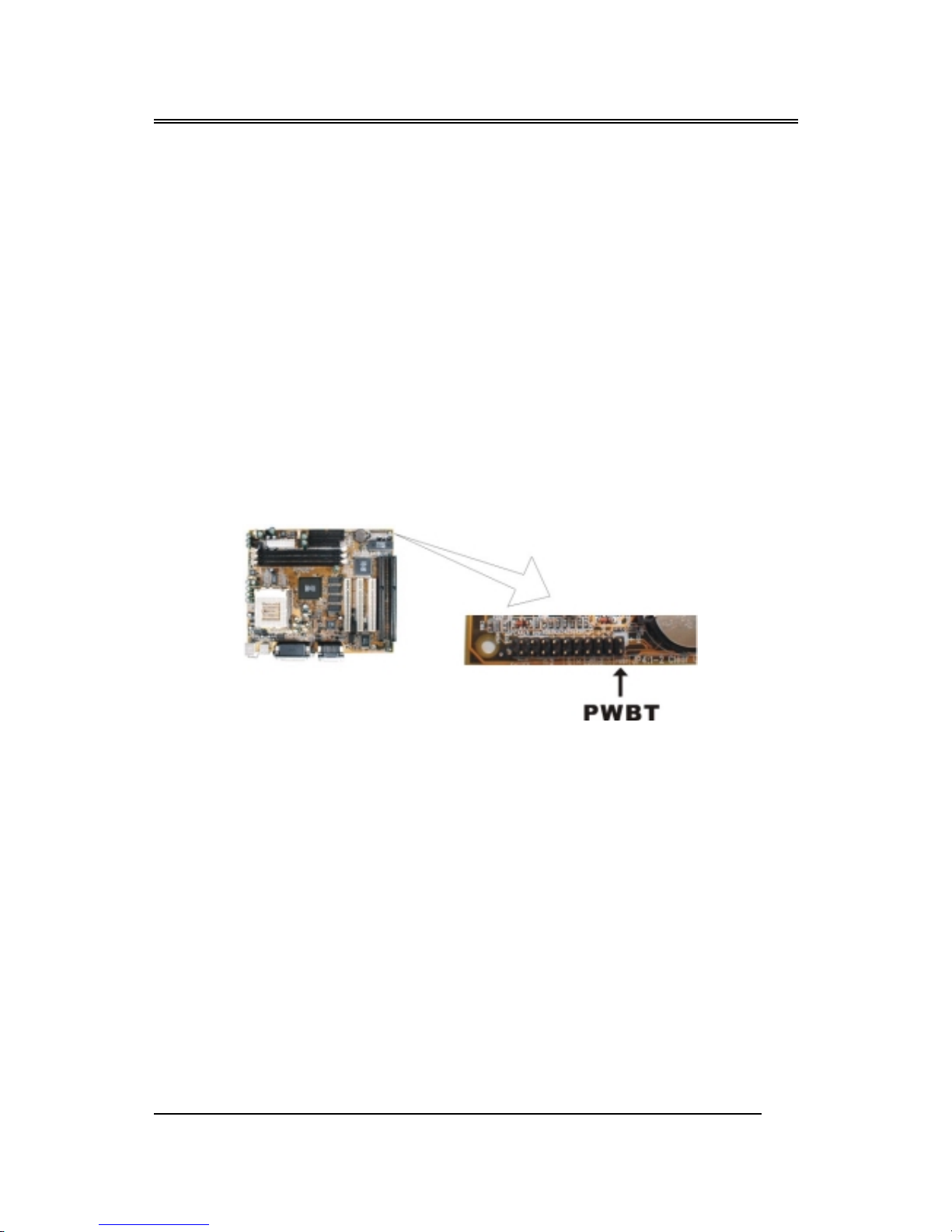
1.5 POWER OFF CONTROL SOFTWARE
Our motherboards are all designed to support software-based shutdowns
through the SMI code in Windows 95/98. As it is an Micro-ATX form factor,
an ATX power supply should be used.
First, connect the power switch cable (provided by the case supplier) to
the connector [PWBT] on the motherboard (see below). To activate this
feature, enter the BIOS setup program and under POWER MANAGEMENT
SETUP, choose "User Defined" (or the minimum or maximum power saving
settings) in POWER MANAGEMENT and select YES under the option “PM
Control by APM.”
Note: BIOS Setup. Please refer the “Chapter 3 Award BIOS Setup”
When you select “Shutdown” in Windows 95/98, the computer's power
will be switched off automatically, and the computer will enter a suspended
mode, indicated by a blinking power light. To restart the system, simply press
the power button.

BS61Mseries
~9~
1.6 PACKAGING CHECK LIST
Your motherboard should come securely packed in a box and shipping
carton. If any of the items below are missing or damaged, please contact your
supplier immediately.
The motherboard contains:
QUANTITY DESCRIPTION
1 Motherboard
: With
SiS620/SiS5595 chipset
1 Driver : CD-Title w/Installation label
• PC-Cillin Software
• Motherboard Bus master Driver
• Audio Driver and AP
1 Cable
: IDE Cable
1 Cable : Floppy Cable
1 Cable : COM2 Cable
1 User’ s guide : PC-Cillin
1 Manual
: User’ s manual
BS61Mseries
~10~
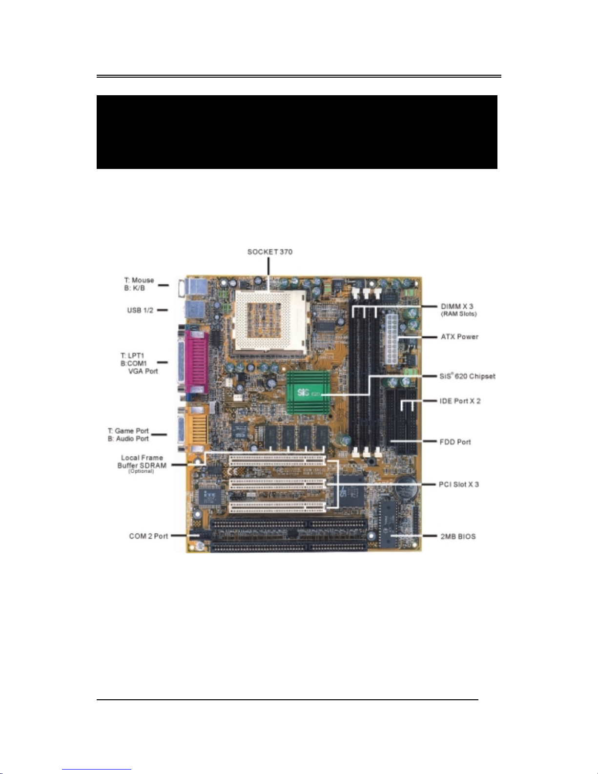
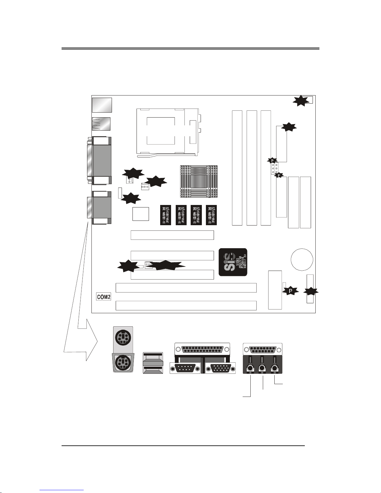
2.1 Motherboard layout
Chapter 2
Setup Guide
BS61Mseries
~11~
2.2 Connector & Jumper Reference Chart
Socket 370
KQ2
KQ3
KQ4
KQ2
KQ3
KQ4
KQ2
KQ3
KQ4
KQ2
KQ3
KQ4
FAN1
FAN2
CD-IN
ATX Pow e r
J4
FDD
IDE1
IDE2
IrDA
Wake-ON-LAN
J 4
J17
BIOS
3V
Battery
PCI 1
PCI 2
PCI 3
ISA 1
ISA 2
DIMM1
DIMM2
DIMM3
KB
USB
COM1
VGA OUT
MS
PRN
Line out
Line In
MIC
MIDI/Game
Connector Front View
ESS
Audio
J 6
J 7
(JP8:Reserve)
JP8
BS61Mseries
~12~
2.3 The setup steps
Please perform the following steps to setup your computer:
I. Refer to the "Jumper Setup" section to set jumpers correctly.
II. Install the DIMM modules on the motherboard (please be sure to set
them up safely).
III. Install the CPU on the motherboard (please refer to the CPU
installation manual).
IV. Choose a case and attach the motherboard in to the case.
V. Plug in any interface cards you may have.
VI. Connect the cable, power supply and other messages lines in the
correct position.
VII. Reboot, and enter the Award BIOS setup menu to correct
configuration settings.
VIII. Turn on the power, and set up your computer system software.
2.3-1 Jumper & Connector Setting
BS61Mseries motherboards are advanced motherboards that can
automatically detect CPUs, and they allow you to select the CPU clock
frequency and the CPU frequency ratio in BIOS setup. You can also choose
whether to enable or disable on-board audio functions. All these settings are
mode in the BIOS, rather than through jumpers.
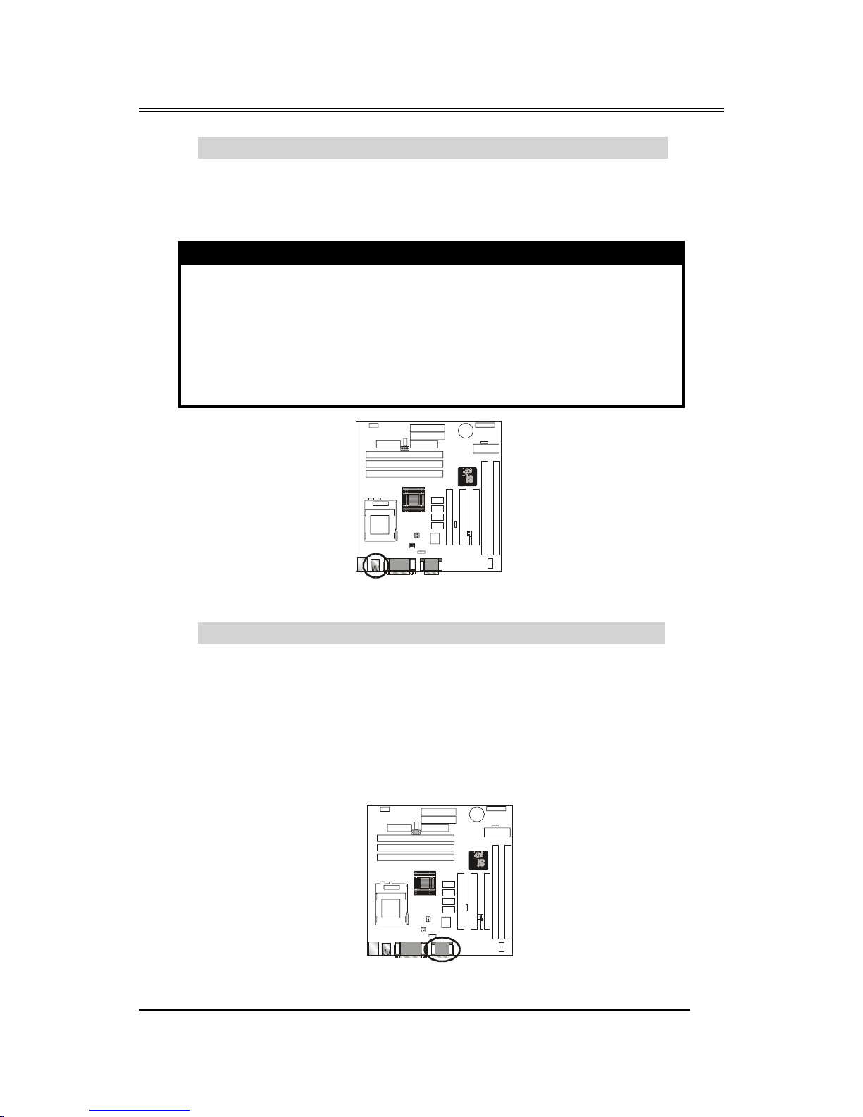
PS1- PS/2 Keyboard Connector Color : Purple ; Panton : 2715C
This connector can connect PS/2 Keyboard and has better
performance.
Pin Description Pin Description
1 Keyboard Data 2,6 N.C.
3 Ground 4 +5V
5 Keyboard Clock
FAN1
FAN2
3V
Battery
BS61Mseries
~13~
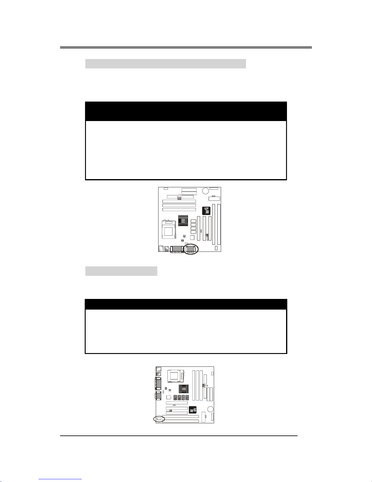
PS2- PS/2 Mouse Connector Color : Green ; Panton : 3395C
This connector can connect PS/2 Mouse and has better performance.
Pin Description Pin Description
1 Mouse Data 2,6 N.C.
3 Ground 4 +5V
5 Mouse Clock
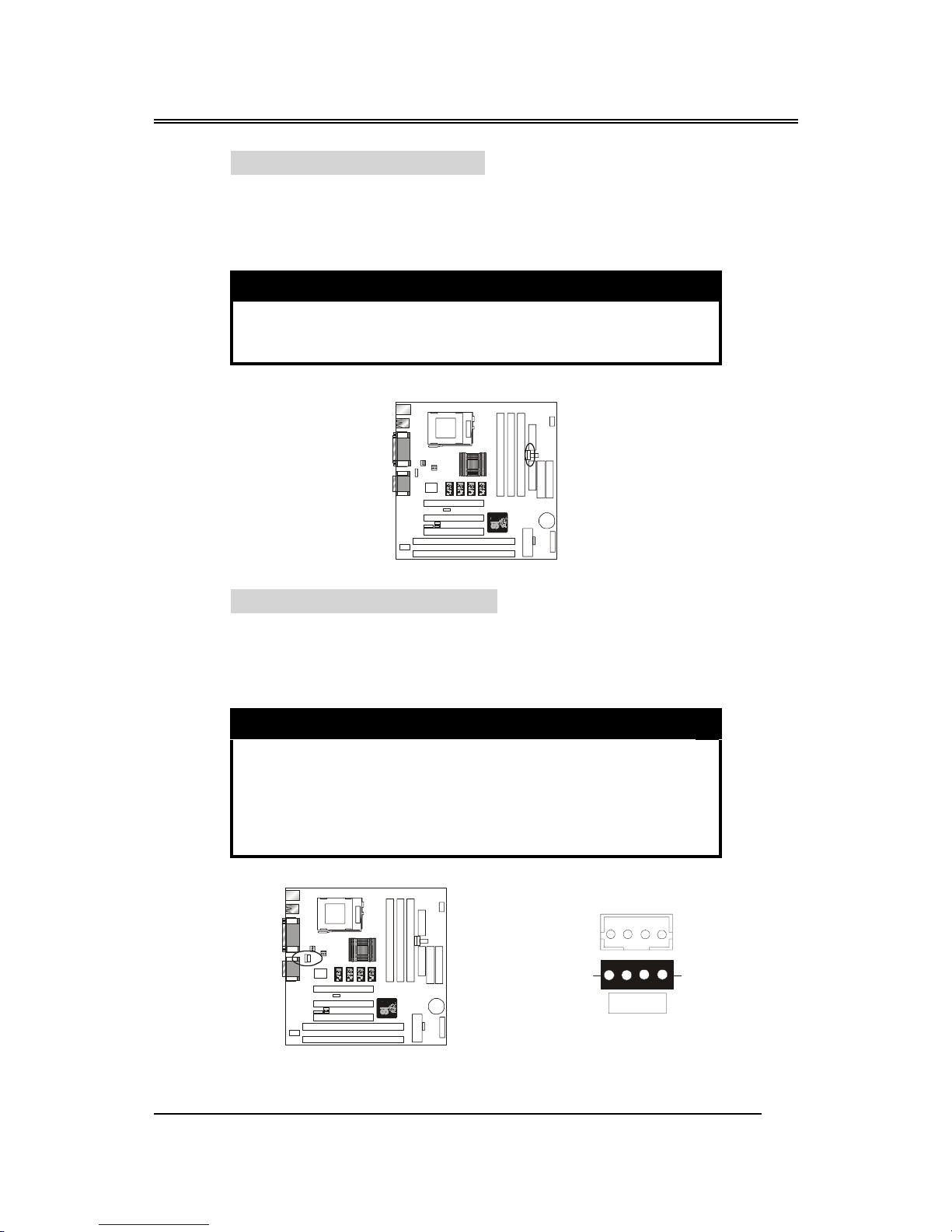
J4 - ATX Power Supply Connector
This connector allows the motherboard to draw the power from ATX
power supply. It requires an ATX power supply of 250 watt at least.
Pin Description Pin Description
1,2,11 + 3.3 V 3,5,7,13,1
5,16,17
Ground
4,6,19,20 + 5 V 8 POWER GOOD
9 5VSB 10 +12 V
12 -12 V 14 PS-ON
18 - 5 V
FAN1
FAN2
3V
Battery
FAN1
FAN2
3V
Battery

BS61Mseries
~14~
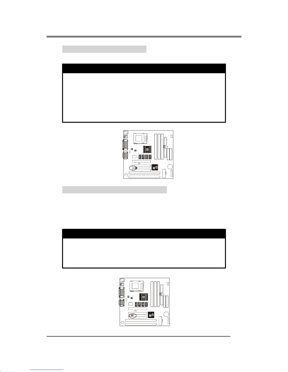
PRINTER - Printer Connector Color : Burgundy ; Panton : 235C
This Connector can transfer the data to printer for printing.
Pin Signal Name Pin Signal Name
1 Strobe- 14 AFD
2 Data Bit 0 15 Error
3 Data Bit 1 16 INIT
4 Data Bit 2 17 SLCTIN
5 Data Bit 3 18 GND
6 Data Bit 4 19 GND
7 Data Bit 5 20 GND
8 Data Bit 6 21 GND
9 Data Bit 7 22 GND
10 ACK 23 GND
11 Busy 24 GND
12 PE 25 GND
13 SLCT 26 GND
FAN1
FAN2
3V
Battery
BS61Mseries
~15~
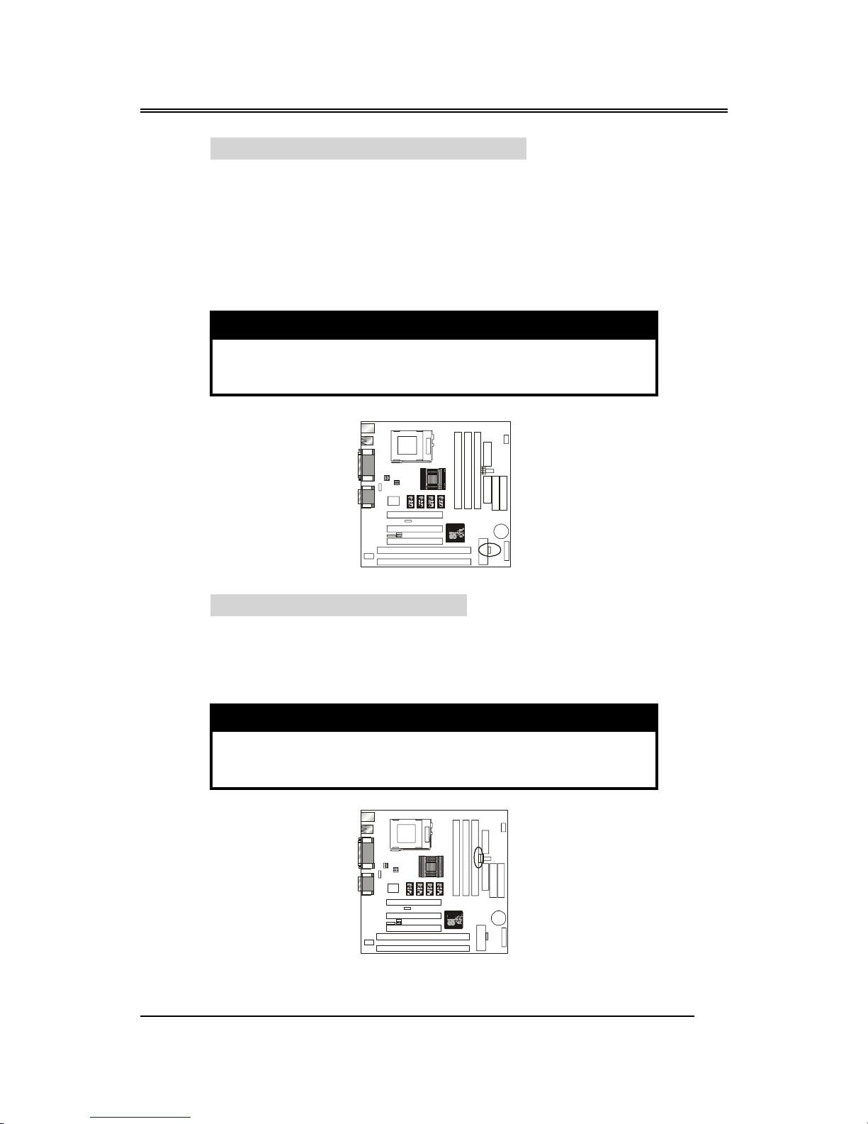
COM1 –Serial Connector Color : Turquoise ; Panton : 322C
This connector allows mouse or the other RS-232 device which
use this type connector to transfer data between computer and
devices.
Pin Signal Name Pin Signal Name
1 DCD 6 DSR
2 SIN 7 RTS
3 SOUT 8 CTS
4 DTR 9 RI
5 GND 10 NC
VGA – VGA Out Connector Color : Blue ; Panton : 661C
This connector is for the external monitor. Use this port to connect
to a VGA or higher resolution display monitor.
Pin Signal Name Pin Signal Name
1 RED Signal 9 N.C.
2 GREEN Signal 10 GND
3 BLUE Signal 11 N.C.
4 N.C. 12 Display data channel data
5 GND 13 Horizontal Sync
6 GND 14 Vertical Sync
7 GND 15 Display data channel clock
8 GND
FAN1
FAN2
3V
Battery
FAN1
FAN2
3V
Battery
BS61Mseries
~16~
USB - Universal Serial Bus (USB1, USB2) Connectors
Color : Black ; Panton : 426C
These connectors allow the device which use this type connector to
transfer information between computer and devices.
USB1 Pin Signal Name USB2 Pin Signal Name
1 USB VCC 0 1 USB VCC 1
2 USB Data - 2 USB Data -
3 USB Data + 3 USB Data +
4 USB GND 0 4 USB GND 1
5 GND 5 GND
Audio Jacks – For Line-In, Line-Out, Mic. Connectors
Line-In - Color: Light Blue ; Panton : 284C
Line-Out - Color: Lime ; Panton :
577C
Mic - Color: Pink
; Panton : 701C
These jacks are for audio functions. The left side jack is for a
stereo line out signal. The middle jack is for a stereo line in signal.
The right side jack is for a microphone.
FAN1
FAN2
3V
Battery
FAN1
FAN2
3V
Battery
BS61Mseries
~17~
GAME/MIDI – For Game or MIDI Connector
Color: Gold ; Panton : 131C
You can use this port to connect a joystick or a MIDI device to
your system.
Pin
Signal
Name
Pin
Signal
Name
Pin
Signal
Name
1 VCC 6 TB 11 TC
2 SWA 7 SWD 12 MSD
3TA8VCC 13 TD
4 GND 9 VCC 14 SWD
5 GND 10 SWC 15 MSI
COM2 –Serial Port
This connector allows mouse or the other RS-232 device which use
this type connector to transfer data between computer and devices.
Pin Signal Name Pin Signal Name
1 DCD 6 DSR
2 SIC 7 RTS
3 SOUT 8 CTS
4 DTR 9 RI
5 GND 10 N.C.
FAN1
FAN2
3V
Battery
KQ2
KQ3
KQ4
KQ2
KQ3
KQ4
KQ2
KQ3
KQ4
KQ2
KQ3
KQ4
FAN1
FAN2
3V
Battery
BS61Mseries
~18~
IrDA - Infrared Connector: IR
This connector is used to connect IR Device.
Pin Signal Name
1
VCC
2
--------
3
SIRRX
4
GND
5
IRTX
WOL – Wake-up On LAN Connector
This connector is used to connect an add-in NIC ( Network
Interface Card ) which gives WOL function to the motherboard. Enable
this function for remotely managing PC on a network. When a PC
receives the wake up command during sleep, the LAN controller will
wake up the PC.
Pin Signal Name
1
5VSB
2
GND
3
LID
KQ2
KQ3
KQ4
KQ2
KQ3
KQ4
KQ2
KQ3
KQ4
KQ2
KQ3
KQ4
FAN1
FAN2
3V
Battery
KQ2
KQ3
KQ4
KQ2
KQ3
KQ4
KQ2
KQ3
KQ4
KQ2
KQ3
KQ4
FAN1
FAN2
3V
Battery
BS61Mseries
~19~
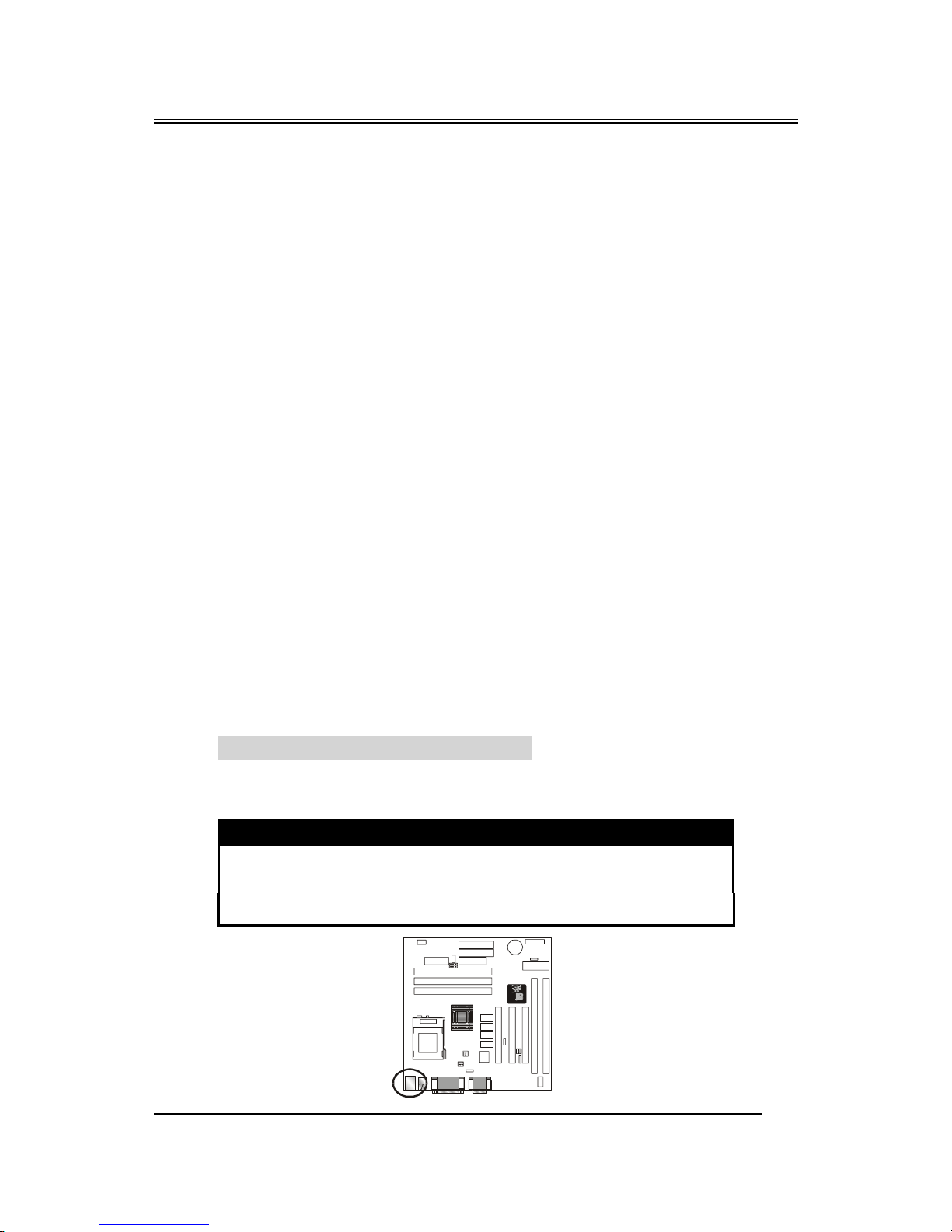
JP4 – Clear CMOS Memory Jumper
This jump lets you erase the system setup settings that are stored
in CMOS memory. You might need to erase this data if incorrect
settings are preventing your system from operating. To clear the
CMOS memory, turn off the system, disconnect the power cable
from the motherboard, and short the appropriate pins for a few
seconds.
JP4 Description
1-2 Clear CMOS
2-3 Normal (default)
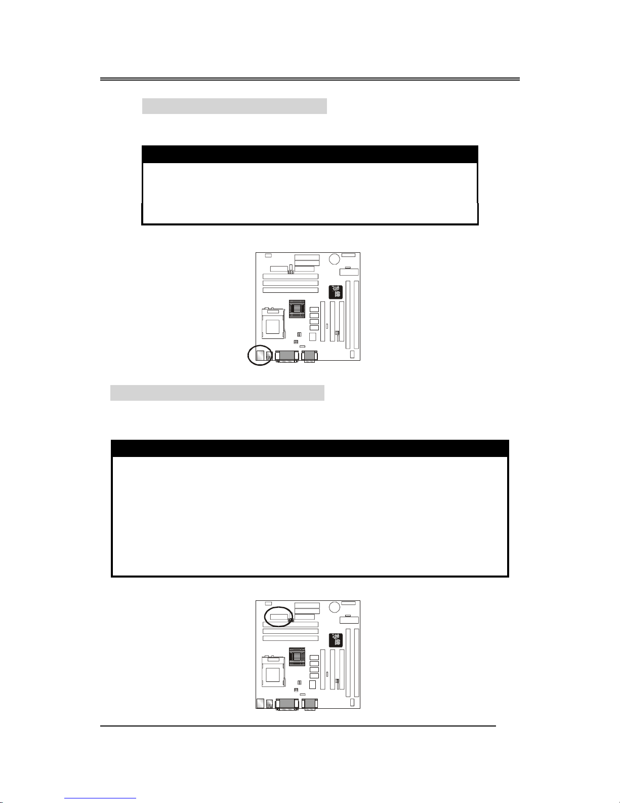
JP6 – Display Memory Select
This jumper is used to select your system display memory mode
control your system power. You can use either Share Memory or
Local Frame Buffer.
Pin Description
1-2 Share System Memory
2-3 Use Local Frame Buffer
KQ2
KQ3
KQ4
KQ2
KQ3
KQ4
KQ2
KQ3
KQ4
KQ2
KQ3
KQ4
FAN1
FAN2
3V
Battery
KQ2
KQ3
KQ4
KQ2
KQ3
KQ4
KQ2
KQ3
KQ4
KQ2
KQ3
KQ4
FAN1
FAN2
3V
Battery
BS61Mseries
~20~
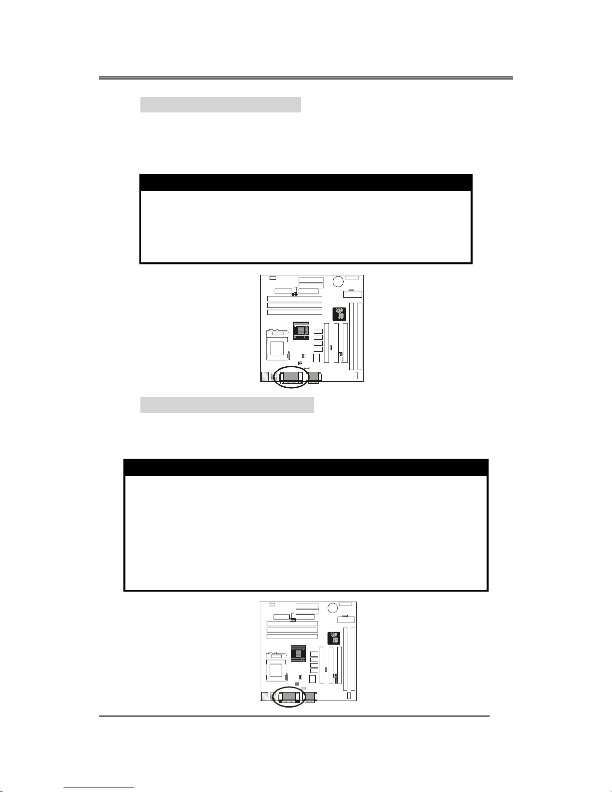
JP7 – VGA Enable/Disable
This jumper lets you enable or disable the video function that is
integrated on the motherboard. You must disable the video function
if you install a VGA interface card using one of the PCI slots.
Pin Description
1-2 Disable on board video function
2-3 Enable on board video function
CD-IN: CD audio Connector
This connector is used to connect CD-ROM audio output to
motherboard, through this, the CD audio can output to ESS audio
chip directly.
Pin Description
1 Left
2 Ground
3 Ground
4 Right
KQ2
KQ3
KQ4
KQ2
KQ3
KQ4
KQ2
KQ3
KQ4
KQ2
KQ3
KQ4
FAN1
FAN2
3V
Battery
KQ2
KQ3
KQ4
KQ2
KQ3
KQ4
KQ2
KQ3
KQ4
KQ2
KQ3
KQ4
FAN1
FAN2
3V
Battery
Left
Right
CD-IN
2
5
 Loading...