

Procomp b686 User Manual

Contents
i
CONTENTS
CH1. MOTHERBOARD FEATURE...........................................................1
!SPECIFICATIONS..........................................................................1
!POWER OFF CONTROL SOFTWARE .........................................3
!PACKAGING CHECK LIST ..........................................................4
CH2. SETUP GUIDE ....................................................................................5
!MAINBOARD LAYOUT DRAWING ...........................................5
!JUMPER & CONNECTOR SETTING ...........................................6
CPU TYPE SELECT ......................................................................6
CONNECTOR SETTING ...............................................................6
FAN CONNECTOR .....................................................................10
JP10 OTHER JUMPER SETTING ..............................................10
!MEMORY INSTALLATION........................................................12
CH3. AWARD BIOS SETUP......................................................................13
!THE MAIN MENU .......................................................................15
!STANDARD CMOS SETUP ........................................................17
!BIOS FEATURES SETUP ............................................................18
!CHIPSET FEATURES SETUP .....................................................24
!POWER MANAGEMENT............................................................25
!PNP / PCI CONFIGURATION SETUP ........................................31
!INTEGRATED PERIPHERALS ...................................................33
!LOAD BIOS DEFAULT ...............................................................34
!LOAD SETUP DEFAULT ............................................................34
!SUPERVISOR / USER PASSWORD SETTING..........................34
!IDE HDD AUTO DETECTION....................................................35
CH4. WINBOND W83781D SETUP DUIDE.................................................36
✒
SLOT1 CPU INSTALLATION GUIDE ...................................................P-1
REMARK
INTEL
®
is a registered trademark of Intel Corporation.
All other brands and product names are trademarks registered trademarks of their
respective companies.

B686
1
SPECIFICATIONS
System Chipset
Intel
®
440LX chip set ,Winbond 83977TF-AW
CPU
Pentium
®
II Klamath CPU 233MHz ~ 333MHz
Memory Subsystem
Expandable to 384MB(3 banks) with 168-Pin
SDRAM(DIMM) Socket X3
Integrated I / O
Two high speed 16550 compatible serial ports, one
Multi-Mode Parallel Port fixed SPP/EPP/ECP
standard
Two PCI Bus master Ultra DMA/33 IDE port (up to
4 IDE Devices)
Support two 360KB / 720KB / 1.2MB / 1.44MB /
2.88MB / floppy disk driver
Support LS120 drives, ZIP 100 drives
Support two USB ports
Support IrDA TX / RX header
Chapter 1
Motherboard
Feature
Introduction

B686
2
On-Board W83781D
CPU/Power Supply /chassis Fan Revolution
Detect
CPU Fan Control ( the fan will automatically stop
when the system enters suspend mode)
CPU Overheat Warning(reserved)
Chassis Intrusion Detect (reserved)
Display Actual Current Voltage
BIOS
1MB Flash ROM
Award AGP BIOS with green, plug and play, ACPI,
DMI feature support
Support secondary device boot
Expansion slot
Four 32-bit PCI Slots & three 16-bit ISA Slots
Support 3.3/5V PCI 2.1 bus Interface
EXTRA Function
Support Keyboard and PS/2 Mouse ON-NOW
Function
Suspend LED on/off
Win95 soft power off
External SMI
Wake up by ring

B686
3
Keyboard Connector
PS/2 Keyboard and PS/2 mouse Connector
Others
Windows 95 Compatible
Dimension
ATX size (350mm x 190mm), 4-layer PCB
POWER OFF CONTROL SOFTWARE
The motherboard design supports software power off Control feature
through the SMM code in the BIOS under Win95 operating system
environment. This is INTEL ATX form factor feature and you should use
ATX power supply.
First, you should connect the power switch cable (provided by the ATX
case Supplier) to the connector [ PW_ON ] on the motherboard. In the BIOS
screen of “POWER MANAGEMENT SETUP”, choose “User Defined”(or
min power saving or Max power saving) in “POWER MANAGEMENT” and
choose “Yes” in “PM Control by APM”.
In Windows 95 the “ SHUT DOWN “ option , the computer’ s Power will
switch off automatically and put the PC in a suspend mode. A bunking power
light will indicate this. To restart the system , simply press the Power Button.

B686
4
PACKAGING CHECK LIST
The motherboard comes securely packed in a durable box and shipping
carton. If any of the above items are missing or damaged , please contact
your supplier.
The motherboard contains:
Q’TY Description
1
Motherboard : B686
1
Diskette : Bus master driver
Award system BIOS utility W83781D AP
1
Cable : Enhanced IDE connector
1
Cable : F.D.D connector
1 Manual : User’s manual
1 Temperature Resister : use for temperature sensor

B686
5
Motherboard Layout Drawing
Chapter 2
Setup
Guide
ATX POWER
Connector
SLOT 1
Intel
440LX
AGP set
CPU Fan
1
3
DIMM1
DIMM2
DIMM3
FDD Connector
IDE 1
IDE 2
AGP SLOT
PC I 1
PC I 2
PC I 3
PC I 4
Winbond
W83977F-AW
JP1
3V
Battery
JP5
JP6
JP7
JP8
ISA 1
ISA 2
ISA 3
BIOS
Intel
FW82371AB
PCI se t
C PU FREQ JP5 JP6 JP7 JP8
233 M Hz S 0 0 S
266 MHz 0 S S S
300 MHz 0 S 0 S
333 MHz 0 0 S S
USB 1 / 2
T: LPT1
B:COM1/2
T: Mouse
B: K/B
JP9
W83781D
JP2
B686
6
Jumper & Connector Setting
CPU TYPE SELECTION
Processor Core FREQ
SYSTEM BUS FREQ
JP5 JP6 JP7 JP8
3.5 233 MHz
Short Open Open Short
4 266 MHz
Open Short Short Short
4.5 300 MHz
Open Short Open Short
5 333 MHz
Open Open Short Short
CONNECTOR SETTING
U1- PS/2 Keyboard Connector
Pin Description
1 Keyboard Data
2,6 N.C.
3 Ground
4 +5V
5 Keyboard Clock
Short
Open

B686
7
J4- Power Supply Connector
Pin Description
1,2,11 + 3.3 V
3,5,7,13,15,16,17 Ground
4,6,19,20 + 5 V
8 POWER GOOD
9 5VSB
10 +12 V
12 -12 V
14 PS-ON
18 - 5 V
U2- PS/2 Mouse Connector
Pin Description
1 Mouse Data
2,6 N.C.
3 Ground
4 +5V
5 Mouse Clock

B686
8
J1- PRINTER Connector
Pin Signal Name Pin Signal Name
1 Strobe- 14 AFD
2 Data Bit 0 15 Error
3 Data Bit 1 16 INIT
4 Data Bit 2 17 SLCTIN
5 Data Bit 3 18 GND
6 Data Bit 4 19 GND
7 Data Bit 5 20 GND
8 Data Bit 6 21 GND
9 Data Bit 7 22 GND
10 ACK 23 GND
11 Busy 24 GND
12 PE 25 GND
13 SLCT 26 GND
COM1,COM2(PJ1,PJ2) –Serial Connectors
Pin Signal Name Pin Signal Name
1 DCD 6 DSR
2 SIN 7 RTS
3 SOUT 8 CTS
4 DTR 9 RI
5 GND 10 NC

B686
9
J3(USB1,USB2)- Universal Serial Bus (USB) Connectors
USB1 Pin Signal Name USB2 Pin Signal Name
1 USB VCC 0 1 USB VCC 1
2 USB Data - 2 USB Data -
3 USB Data + 3 USB Data +
4 USB GND 0 4 USB GND 1
J2- Infrared Connector: IR
Pin Signal Name
1
VCC
2
FIRRX (N)
3
IRRX
4
GND
5
IRTX
7
CIRRX (N)
8
5VSB
6,9,10
NC
B686
10
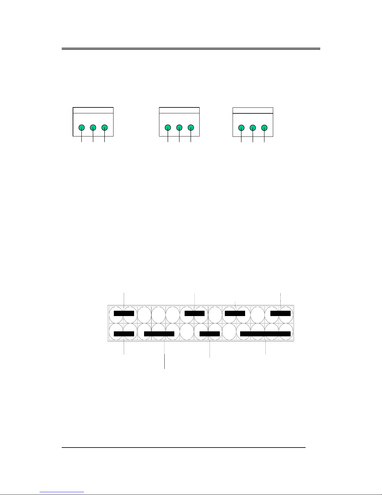
FAN CONNECTOR
JP2: For CPU COOL FAN CONNECTOR
***this fan can be controlled by w83781D AP ***(on/off)
JP4: This fan is used in CPU COOL FAN.
JP9: FAN CONNECTOR
***controlled by w83781D AP***
JP10 OTHER JUMPER SETTING
1
23
JP4
GND +12V GND
1
2 3
JP2
Fan Out +12V FanIN
1
2 3
JP9
GND +12V FanIN
K
+
+
+
P2 5
P2 6
P1
P2
SPEAKER
RESET
EXTSMI
SUS_LEDON
PB_BT
PWR_LED
KEYLOCK
HDDLED
 Loading...