


Contents
i
CONTENTS
CH1. MOTHEROARD FEATURE .............................................................1
!SPECIFICATIONS ..........................................................................1
!POWER OFF CONTROL SOFTWARE .........................................3
!PACKAGING CHECK LIST ..........................................................3
CH2. SETUP GUIDE.....................................................................................4
!MAINBOARD LAYOUT DRAWING............................................4
!JUMPER & CONNECTOR SETTING ...........................................6
CONNECTOR SETTING ...............................................................6
JP3 OTHER JUMPER SETTING ..................................................9
CPU TYPE SELECT ....................................................................10
FAN CONNECTOR......................................................................15
!MEMORY INSTALLATION........................................................16
CH3. AWARD BIOS SETUP......................................................................17
!THE MAIN MENU .......................................................................19
!STANDARD CMOS SETUP.........................................................21
!BIOS FEATURES SETUP ............................................................22
!CHIPSET FEATURES SETUP .....................................................28
!POWER MANAGEMENT............................................................29
!PNP / PCI CONFIGURATION SETUP ........................................34
!INTEGRATED PERIPHERALS ...................................................36
!LOAD BIOS DEFAULT ...............................................................37
!LOAD SETUP DEFAULT ............................................................37
!SUPERVISOR / USER PASSWORD SETTING..........................37
!IDE HDD AUTO DETECTION....................................................38
CH4. WINBOM W83781D SETUP GUIDE..............................................39
✒
PENTIUM® II CPU INSTALLATION GUIDE…….……………….. 42
REMARK
INTEL
®
is a registered trademark of Intel Corporation.
All other brands and product names are trademarks registered trademarks of their
respective companies.

B683/B680
1
SPECIFICATIONS
System Chipset
Intel
®
440BX chipset, Winbond 83977TF-AW
CPU Bus Speed
Pentium
®
҈ 66/100 MHz CPU
CPU Clock
200MHz ~ 550MHz
Memory Subsystem
Expandable to 384MB(3 banks) with 168-Pin
SDRAM(DIMM) Socket X3
Integrated I / O
Two high speed 16550 compatible serial ports, one
Multi-Mode Parallel Port fixed SPP/EPP/ECP
standard
Two PCI Bus master Ultra DMA/33 IDE port (up to 4
IDE Devices)
Support two 360KB / 720KB / 1.2MB / 1.44MB /
2.88MB / floppy disk driver
Support LS120 drives, ZIP 100 drives
Support two USB ports
Support IrDA TX / RX header
BIOS
2MB Award PnP BIOS with enhanced ACPI feature for
PC98 compliance.
Supports Trend™ ChipAway AntiVirus.
DMI feature support
Support secondary device boot
Chapter 1
Motherboard Feature

B683/B680
2
On-Board W83781D
(Only for B683)
CPU/Power Supply /chassis Fan Revolution Detect
CPU Fan Control ( the fan will automatically stop
when the system enters suspend mode)
CPU Overheat Warning(reserved)
Chassis Intrusion Detect (reserved)
Display Actual Current Voltage
Expansion slot
Four PCI Master Slots & Two 16-bit ISA Slots
Support 3.3/5V PCI bus Interface
EXTRA Function
Suspend LED on/off
Win95 soft power off
External SMI
Wake up by ring
Wake On LAN
Support Keyboard and PS/2 mouse ON NOW
Function
Connector
PS/2 Keyboard and PS/2 mouse Connector
Others
Windows 95 Compatible
Dimension
4-layer PCB, ATX size (305mm x 170mm)

B683/B680
3
POWER OFF CONTROL SOFTWARE
The motherboard design supports software power off Control feature
through the SMM code in the BIOS under Win95 operating system
environment. This is INTEL ATX form factor feature and you should use ATX
power supply.
First, you should connect the power switch cable (provided by the ATX
case Supplier) to the Jumper [ JP1 ] on the motherboard. In the BIOS screen of
“POWER MANAGEMENT SETUP”, choose “User Defined”(or min power
saving or Max power saving)in “POWER MANAGEMENT” and choose
“Yes” in “PM Control by APM”.
In Windows 95 the “ SHUT DOWN “ option ,the computer’ s Power will
switch off automatically and put the PC in a suspend mode. This will be
indicated by a bunking power light. To restart the system , simply press the
Power Button.
PACKAGING CHECK LIST
The motherboard comes securely packed in a durable box and shipping
carton. If any of the above items are missing or damaged , please contact your
supplier.
The motherboard contains:
Q’ TY Description
1 motherboard : B683/B680
1 Diskette
: Bus master driver
Award system BIOS
1 Cable
: Enhanced IDE connector
1 Cable
: F.D.D connector
1 Manual : User’ s manual
1 Temperature Resister: Use for temperature sensor
(Only for B683)
B683/B680
4
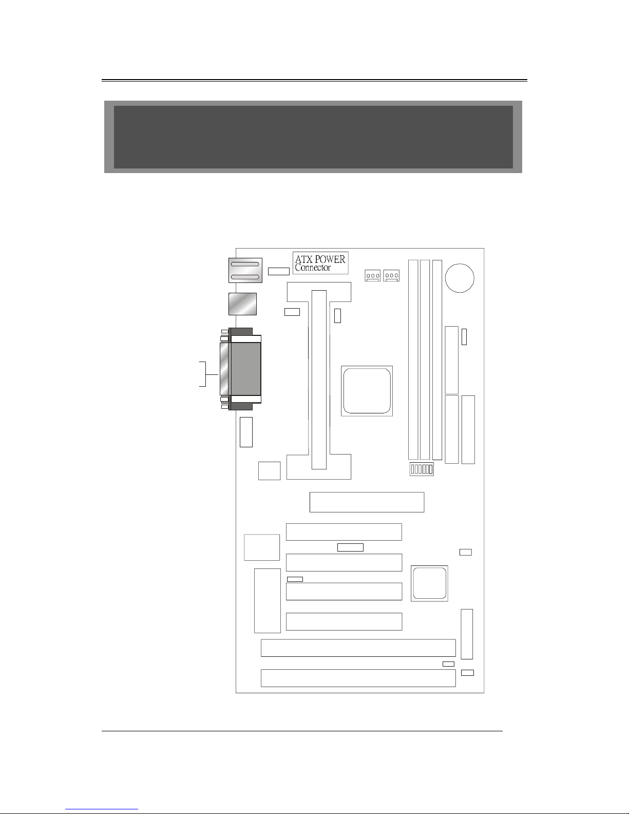
B683 Motherboard Layout Drawing
Chapter 2
SETUP GUIDE
˄˅ˆˇˈ
˄ˆ
˜˦˔ʳ˅
˜˦˔ʳ˄
ˣ˖˜ʳ˄
ˣ˖˜ʳ˅
ˣ˖˜ʳˆ
ˣ˖˜ʳˇ
˔˚ˣʳ˦˟ˢ˧
˕˜ˢ˦
˦˨ˣ˘˥
˜˂ˢ
˦˘ˡ˦ˢ˥
˦˟ˢ˧ʳ˄
˜˸˿
ˇˇ˃ʳ˕˫
˔˚ˣʳ˸
˜˸˿
ˣ˜˜˫ˇ
ˣ˖˜ʳ˸
˖ˣ˨ʳ˙˔˄
˦ˬ˦ʳ˄
˄ˆ
˄ˆ
˗˜ˠˠ ʳ˄
˗˜ˠˠʳ˅
˗˜ˠˠʳˆ
˜˗˘ʳ˅
˜˗˘ʳ˄
˙˗˖
˝˕˔˧˄
ˆ˩
˕˴˸
˦˪˄
˝ˣ˄
˝ˣˆ
˥˧ˆ
˄
˅˅˅˅˄
˄
ˆ
˄
˄
ˆˇ
˄
˨˦˕ʳ˄˂˅
˧ˍʳ˟ˣ˧˄
˕ˍ˖ˢˠ˄˂˅
˄ˇ
˝ˣ˅
˄ˆ
˦ˬ˦˅
˥˧˄
˥˧˅
˧ˍʳˠ˸
˕ˍʳ˞˂˕
˝˪˥˄
˝˪ˢ˟˄
ˉ
˄
˅
ˉ
ˈ
˝˦˕˄
˄ˆ
˝ˣˇ

B683/B680
5
B680 Motherboard Layout Drawing
˄˅ˆˇˈ
˄ˆ
˜˦˔ʳ˅
˜˦˔ʳ˄
ˣ˖˜ʳ˄
ˣ˖˜ʳ˅
ˣ˖˜ʳˆ
ˣ˖˜ʳˇ
˔˚ˣʳ˦˟ˢ˧
˕˜ˢ˦
˦˨ˣ˘˥
˜˂ˢ
˦˟ˢ˧ʳ˄
˜˸˿
ˇˇ˃ʳ˕˫
˔˚ˣʳ˸
˜˸˿
ˣ˜˜˫ˇ
ˣ˖˜ʳ˸
˖ˣ˨ʳ˙˔˄
˦ˬ˦ʳ˄
˄ˆ
˄ˆ
˗˜ˠˠ ʳ˄
˗˜ˠˠʳ˅
˗˜ˠˠʳˆ
˜˗˘ʳ˅
˜˗˘ʳ˄
˙˗˖
˝˕˔˧˄
ˆ˩
˕˴˸
˦˪˄
˝ˣ˄
˝ˣˆ
˄
˅˅˅˅˄
˄
ˆ
˄
˄
ˆˇ
˄
˨˦˕ʳ˄˂˅
˧ˍʳ˟ˣ˧˄
˕ˍ˖ˢˠ˄˂˅
˄ˇ
˝ˣ˅
˄ˆ
˦ˬ˦˅
˧ˍʳˠ˸
˕ˍʳ˞˂˕
˝˪˥˄
˝˪ˢ˟˄
ˉ
˄
˅
ˉ
ˈ
˝˦˕˄
˄ˆ
˝ˣˇ

B683/B680
6
JUMPER & CONNECTOR SETTING
Connector Setting
KB1- PS/2 Keyboard/ PS/2 Mouse Connector
Pin Description
1 Keyboard Data
2 , 6 N.C.
3 Ground
4 +5V
5 Keyboard Clock
Pin Description
1 Mouse Data
2 , 6 N.C.
3 Ground
4 +5V
5 Mouse Clock
USB1-Universal Series Bus (USB) Connectors
USB1 Pin Signal Name USB2 Pin Signal Name
1 USB VCC 0 1 USB VCC 1
2 USB Data - 2 USB Data -
3 USB DATA + 3 USB DATA +
4 USB GND 0 4 USB GND 1

B683/B680
7
JWR1 - Power Supply Connector
Pin Description
1,2,11 + 3.3 V
3,5,7,13,15,16,17 Ground
4,6,19,20 + 5 V
8 POWER GOOD
9 5VSB
10 +12 V
12 -12 V
14 PS-ON
18 - 5 V
JP2 – Infrared Connector : IR
Pin Signal Name
1
VCC
2
SIRRX
3
GND
4
IRTX
JBAT1 – CMOS CLEAR
Description Pin
Normal (default) 1-2
Clear CMOS 2-3
JWOL1 – WAKE ON LAN
Description Pin
5V Stand-by
1
GND 2
LAN IN
3

B683/B680
8
LPT1- PRINTER Connector
Pin Signal Name Pin Signal Name
1 Strobe- 14 AFD
2 Data Bit 0 15 Error
3 Data Bit 1 16 INIT
4 Data Bit 2 17 SLCTIN
5 Data Bit 3 18 GND
6 Data Bit 4 19 GND
7 Data Bit 5 20 GND
8 Data Bit 6 21 GND
9 Data Bit 7 22 GND
10 ACK 23 GND
11 Busy 24 GND
12 PE 25 GND
13 SLCT 26 GND
COM1,COM2 - Serial Connectors
Pin Signal Name Pin Signal Name
1 DCD 6 DSR
2 SIN 7 RTS
3 SOUT 8 CTS
4 DTR 9 RI
5 GND 10 NC
JP4 Keyboard & PS/2 Mouse ON NOW Connector
Pin Description
1 VCC
2 K/B & PS/2 M.S.
3 5VSB

B683/B680
9
Note : 1-2 Disabled (Default) 2-3 Enabled
JSB1 – For Sideband Signals Connector
Ex. Creative SB-LINK Connector
Pin Signal Name
1 -GNTA
2,5 GND
3NA
4 -REQA
6 SERIRQ
JP3 – OTHER JUMPER SETTING
Pin Name Description
1 - 3 Reset Reset buttom
7 - 9 HDD_LED Hard Disk LED
13 - 15 EXT_SMI Suspend mode
19 - 21 SUS_LED Suspend LED
2 - 6 Power_LED Power LED
8 - 10 KEY_ Lock Key Lock
14 - 20 SPK Speaker
P2 P22
P1
P21
Power_LED KEY_Lock
SPK
Reset
HDD_LED
EXT_SMI
SUS_LED

B683/B680
10
JP1 - POWER BUTTON
Pin Description
1-3 ON/OFF

B683/B680
11
CPU TYPE Select
CPU Bus Speed - 66MHz part :
1. 200MHz
SW1-1 SW1-2 SW1-3 SW1-4 SW1-5 SW1-6
ON ON OFF ON ON ON
2. 233MHz
SW1-1 SW1-2 SW1-3 SW1-4 SW1-5 SW1-6
ON OFF OFF ON ON ON
3. 266MHz
SW1-1 SW1-2 SW1-3 SW1-4 SW1-5 SW1-6
ON ON ON OFF ON ON
4. 300MHz
SW1-1 SW1-2 SW1-3 SW1-4 SW1-5 SW1-6
ON OFF ON OFF ON ON
12345
CTS 208-6 T808
6
12345
CTS 208-6 T808
6
12345
CTS 208-6 T808
612345
CTS 208-6 T808
6
12345
CTS 208-6 T808
6

B683/B680
12
5. 333MHz
SW1-1 SW1-2 SW1-3 SW1-4 SW1-5 SW1-6
ON ON OFF OFF ON ON
6. 366MHz
SW1-1 SW1-2 SW1-3 SW1-4 SW1-5 SW1-6
ON OFF OFF OFF ON ON
7. 400MHz
SW1-1 SW1-2 SW1-3 SW1-4 SW1-5 SW1-6
OFF ON ON ON ON ON
8. 433MHz
SW1-1 SW1-2 SW1-3 SW1-4 SW1-5 SW1-6
OFF OFF ON ON ON ON
12345
CTS 208-6 T808
612345
CTS 208-6 T808
6
12345
CTS 208-6 T808
612345
CTS 208-6 T808
6
23456
DUT!319.7!U919
723456
DUT!319.7!U919
7
23456
DUT!319.7!U919
723456
DUT!319.7!U919
7
B683/B680
13
9. 466MHz
SW1-1 SW1-2 SW1-3 SW1-4 SW1-5 SW1-6
OFF ON OFF ON ON ON
10. 500MHz
SW1-1 SW1-2 SW1-3 SW1-4 SW1-5 SW1-6
OFF OFF OFF ON ON ON
12345
CTS 208-6 T808
612345
CTS 208-6 T808
6
12345
CTS 208-6 T808
612345
CTS 208-6 T808
6

B683/B680
14
CPU Bus Speed - 100MHz part :
1. 300MHz
SW1-1 SW1-2 SW1-3 SW1-4 SW1-5 SW1-6
ON ON OFF ON OFF OFF
2. 350MHz
SW1-1 SW1-2 SW1-3 SW1-4 SW1-5 SW1-6
ON OFF OFF ON OFF ON
3. 400MHz
SW1-1 SW1-2 SW1-3 SW1-4 SW1-5 SW1-6
ON ON ON OFF OFF ON
4. 450MHz
SW1-1 SW1-2 SW1-3 SW1-4 SW1-5 SW1-6
ON OFF ON OFF OFF ON
1
2345
CTS 208-6 T808
6
1
2345
CTS 208-6 T808
6
12345
CTS 208-6 T808
612345
CTS 208-6 T808
6
12345
CTS 208-6 T808
612345
CTS 208-6 T808
6
12345
CTS 208-6 T808
612345
CTS 208-6 T808
6

B683/B680
15
5. 500MHz
SW1-1 SW1-2 SW1-3 SW1-4 SW1-5 SW1-6
ON ON OFF OFF OFF ON
6. 550MHz
SW1-1 SW1-2 SW1-3 SW1-4 SW1-5 SW1-6
ON OFF OFF OFF OFF ON
12345
CTS 208-6 T808
612345
CTS 208-6 T808
6
12345
CTS 208-6 T808
612345
CTS 208-6 T808
6

B683/B680
16
CPU TYPE SELECT LIST
SW1-1,2,3,4 (For RATIO select)
RATIO SW1-1 SW1-2 SW1-3 SW1-4
3.0 ON ON OFF ON
3.5 ON OFF OFF ON
4.0 ON ON ON OFF
4.5 ON OFF ON OFF
5.0 ON ON OFF OFF
5.5 ON OFF OFF OFF
SW1-5 (For BUS clock)
CLOCK SW1-5
66 MHz ON
100 MHz OFF
SW1-6 (CPU BUS Clock manual / Auto detect)
CLOCK SW1-6
Default (Auto Detect) ON
Force BUS CLOCK up to 100 MHz OFF
FAN CONNECTOR
CPU FA1
GND
Fan In
Fan Out
SYS 1
GND
Fan In
Fan Out
SYS 2
GND
Fan In
Fan Out

B683/B680
17
MEMORY INSTALLATION
No jumper setting is necessary for DRAM setting, BIOS will check
DRAM type and size automatically. B683 motherboard contains 3 by
168-pin DIMM sockets(DIMM1,DIMM2,DIMM3). B683 motherboard has
table-free ( or auto-bank ) feature and user can install DIMM into any
bank. The three DIMMs Sockets for system memory expansion from
8MB to 384 MB. Each bank provides 64-bit wide data path.
NOTE: Samples of System Memory Combinations Options
DIMM1 DIMM2 DIMM3 TOTAL
8MB --- --- 8MBytes
--- 8MB --- 8MBytes
--- --- 8MB 8MBytes
8MB 8MB --- 16MBytes
--- 8MB 8MB 16MBytes
8MB --- 8MB 16MBytes
16MB --- --- 16MBytes
--- 16MB --- 16MBytes
--- --- 16MB 16MBytes
8MB 8MB 8MB 24MBytes
16MB 8MB --- 24MBytes
16MB --- 16MB 32MBytes
16MB 16MB --- 32MBytes
--- --- 32MB 32MBytes
--- 32MB --- 32MBytes
32MB --- --- 32MBytes
8MB 16MB 16MB 40MBytes
32MB 32MB --- 64MBytes
--- 32MB 32MB 64MBytes
64MB --- --- 64MBytes
64MB 64MB --- 128MBytes
64MB 64MB --- 128MBytes
: : : :
: : : :
128MB 128MB 128MB 384MBytes

B683/B680
17
Award BIOS ROM has a built-in Setup program that allows users to
modify the basic system configuration. This type information is stored in
battery-backed RAM so that it retains the Setup information when the power is
turned off.
ENTERING SETUP
Power on the computer and press <Del> immediately will allow you to
enter Setup. The other way to enter Setup is to power on the computer , when
the below message appears briefly at the bottom of the screen during the POST
(Power On Self Test), press <Del> key or simultaneously press <Ctrl>, <Alt>,
and <Esc> keys.
TO ENTER SETUP BEFORE BOOT PRESS CTRL-ALT-ESC OR
DEL KEY
If the message disappears before you respond and you still wish to enter
Setup, restart the system to try again by turning it OFF then ON or pressing the
"RESET" button on the system case. You may also restart by simultaneously
press <Ctrl>, <Alt> and <Del> keys. If you do not press the keys at the correct
time and the system does not boot , an error message will be displayed and you
will again be asked to,
PRESS F1 TO CONTINUE, CTRL-ALT-ESC OR DEL TO ENTER
SETUP
Control Keys
Up Arrow Move to previous item
Down Arrow Move to next item
Left Arrow Move to the item in the left hand
Chapter 3
AWARD BIOS SETUP

B683/B680
18
Right Arrow Move to the item in the right hand
Esc Key Main Menu Quit and not to save changes to
CMOS
Status Page setup menu and Option Page
Setup Menu Exit current page and return to
Main Menu
PgUp Key Increase the numeric value or make changes
PgDn Key Decrease the numeric value or make changes
F1 Key General help, only for Status Page Setup
Menu and Option Setup
Menu
F2 Key Change color from total 16 colors
F3 Key Calendar, only for Status Page Setup Menu
F4 Key Reserved
F5 Key Restore the previous CMOS value from
BIOS, only for Option
Page Setup Menu
F6 Key Load the default CMOS value from BIOS
default table, only for
Option Page Setup Menu
F7 Key Load the default
F8 Key Reserved
F9 Key Reserved
F10 Key Save all the CMOS changes, only for Main
Menu
Getting Help
Main Menu
The on-line description of the highlighted setup function is displayed at the
bottom of the screen.
Status Page Setup Menu/Option Page Setup Menu
Press F1 to pop up a small help window that describes the appropriate keys
to use and the possible selections for the highlighted item. To exit the Help
Window press <Esc>.

B683/B680
19
The Main Menu
Once you enter Award BIOS CMOS Setup Utility, the Main Menu will
appear on the Screen.. Use arrow keys to select among the items and press to
accept or enter the sub-menu.
ROM PC/ISA BIOS (2A69KPNJ)
CMOS SETUP UTILITY
AWARD SOFTWARE, INC.
STANDARD CMOS SETUP
BIOS FEATURE SETUP
CHIPSET FEATURES SETUP
POWER MANAGEMENT SETUP
PNP/PCI CONFIGURATION
LOAD BIOS DEFAULTS
LOAD SETUP DEFAULTS
INTEGRATED PERIPHERALS
SUPERVISOR PASSWORD
USER PASSWORD
IDE HDD AUTO DETECTION
HDD LOW LEVEL FORMAT
SAVE & EXIT SETUP
EXIT WITHOUT SAVING
Esc : Quit ←↑↓→ : Select Item
F10 : Save & Exit Setup (Shift) F2 : Change Color
Standard CMOS Setup
This setup page includes all the items in a standard compatible BIOS.
BIOS Features Setup
This setup page includes all the items of Award special enhanced features.
Chipset Features Setup
This setup page includes all the items of chipset special features.
Power Management Setup
This menu provides functions for Green products by allowing users to set the
timeout value for monitor and HDD.

B683/B680
20
PNP / PCI CONFIGURATION SETUP
This menu allows the user to modify PNP / PCI configuration function.
Load BIOS Defaults
BIOS defaults indicates the most appropriate value of the system parameter
which the system would be in minimum performance.
Load Setup Defaults
Chipset defaults indicates the values required by the system for the maximum
performance.
INTEGRATED PERIPHERALS
This section page includes all the items of IDE hard drive and Programmed
Input / Output features.
Supervisor / User Password Setting
Change, set, or disable password. It allows you to limit access to the system
and Setup, or just to setup.
IDE HDD Auto Detection
Automatically configure hard disk parameters.
HDD Low Level Format
If supported by your system, this provides a hard disk low level format utility.
Save & Exit Setup
Save CMOS value changes to CMOS and exit setup.
Exit Without Saving
Abandon all CMOS value changes and exit setup.

B683/B680
21
ON NOW FUNCTION
User can select the way to power on system from BIOS Setup. Choose “
Integrated Peripheral “ item , user can setup “ POWER ON FUNCTION”
1. BUTTON ONLY: Power on by power button only.
2. PASSORD: Select “ KB Power on Password” then enter. Key in
password and save CMOS SETUP. Then user can power on
system by Key-in Password.
3. HOT KEY: Select “ HOT KEY Function” ,” HOT KEY POWER ON “
4. Mouse Left: Power on by double click mouse left button.
5. Mouse Right : Power on by double click mouse left button.
Standard CMOS Setup
The item in Standard CMOS Setup Menu are divided into several
categories. Each category includes no, one or more than one setup items. Use
the arrow keys to highlight the item and then use the <PgUp> or <PgDn> keys
to select the value you want in each item.
SPN!QDJ0JTB!CJPT!)3B7:LQOK*
TUBOEBSE!DNPT!TFUVQ
BXBSE!TPGUXBSF-!JOD/
Ebuf!)nn;ee;zz*!;!Uvf-!Efd!3:!2::9
Ujnf!)ii;nn;tt*!;!!:!;!63!;!53
IBSE!EJTLT UZQF
TJ[F DZMT IFBE QSFDPNQ MBOE[ TFDUPS NPEF
Qsjnbsz!Nbtufs!!!!!!!!
Qsjnbsz!Tmbwf!!!!!!!!!!!
Tfdpoebsz!Nbtufs
Tfdpoebsz!Tmbwf
;
;
;
;
1
1
1
1
1
1
1
1
1
1
1
1
1
1
1
1
1
1
1
1
1
1
1
1
OPSNBM
Esjwf!B!!!;!2/55N-!4/6!jo/
Esjwf!C!!!;!Opof
Gmpqqz!4!Npef!Tvqqpsu!;!Ejtbcmf
Wjefp!!!!;!FHB0WHB
Ibmu!Po!;!Bmm-!Cvu!Lfzcpbse
FTD!!!;!!Rvju
G2!!!!!;!!Ifmq
!!!!!!!!!!!!!;!Tfmfdu!Jufn!!!!!!!!!!!!!!!!!!!!QV0QE0,0.;Npejgz
)Tijgu*!G3!!!;!Dibohf!Dpmps
1
1
1
1
OPSNBM
OPSNBM
OPSNBM

B683/B680
22
BIOS Features Setup
ROM PCI/ISA BIOS (2A69KPNJ)
BIOS FEATURE SETUP
AWARD SOFTWARE, INC
Anti-Virus Protection : Enabled Video BIOS Shadow
: Enabled
CPU Internal Cache : Enabled C8000-CBFFF Shadow
: Disabled
External Cache : Enabled CC000-CFFFF Shadow
: Disabled
CPU L2 Cache ECC Checking : Enabled D0000-D3FFF Shadow
: Disabled
Quick Power On Self Test : Enabled D4000-D7FFF Shadow
: Disabled
Boot Sequence : A, C ,SCSI D8000-DBFFF Shadow
: Disabled
Swap Floppy Drive : Disabled DC000-DFFFF Shadow
: Disabled
Boot Up Floppy Seek
:
Enabled
Boot Up NumLock Status : On
Gate A20 Option : Fast
Typematic Rate Setting : Disabled
Typematic Rate (Chars/Sec) : 6
Typematic Delay (Msec) : 250
Security Option : Setup
PCI/VGA Palette Snoop : Disabled
OS Select For DRAM > 64MB : Non-OS2
HDD S.M.A.R.T. capability : Enabled
Report No FDD For WIN95 : No
Esc : Quit ↑↓→← : Selection Item
F1 : Help PU/PD/+/- : Modify
F5 : Old Values (Shift) F2 : Color
F6 : Load BIOS Default
F7 : Load Setup Default
Virus Warning
This category flashes on the screen. During and after system boots up, any
attempt to write to the boot sector or partition table of the hard disk drive will
halt the system and the following error message will appear, in the mean time ,
you can run anti-virus programs to locate the problem.
!WARNING!
Disk boot sector is to be modified
Type "Y" to accept write or "N" to abort write
Award Software, Inc.

B683/B680
23
Enabled Activate automatically when the system boots up causing a
warning message to appear when anything attempts to access
the boot sector or hard disk partition table.
Disabled No warning message to appear when anything attempt to access
the boot sector or hard disk partition table.
CPU Internal Cache/External Cache
These two categories speed up memory access. However, it depends on
CPU/chipset design. The default value is Enabled.
Enabled: Enabled cache
Disabled: Disabled cache
Quick Power On Self Test
This category speeds up Power On Self Test (POST) after you power on the
computer. If it is set to Enable, BIOS will shorten or skip some check items
during POST.
Enabled: Enable quick POST
Disabled: Normal POST
Boot Sequence
This category determines which drive computer searches first for the hard disk
operation system (i.e., DOS).
A, C,SCSI: System will first search for floppy disk drive then second
search hard disk driver, then SCSI driver.

B683/B680
24
C,A,SCSI/ D,A,SCSI/ E,A,SCSI/ F,A,SCSI:
System will first search for IDE hard disk driver ( C: D: or E: or
F:) then second search floppy disk driver then SCSI hard disk
driver.
SCSI,A,C: System will first search SCSI hard disk driver then second
search for floppy disk driver then IDE hard disk driver.
CDROM,C,A:
System will first search for the CDROM driver ( If the CDROM
has a bootable CD title.)and second search hard disk driver then
floppy disk driver .
C,CDROM,A:
System will first search for the hard disk driver and second
search for CDROM driver ( If the CDROM has a bootable CD
title,) then search floppy disk driver.
LS120,C: System will first search LS120 disk driver and second search
for IDE hard disk driver.
Swap Floppy Drive
Users can enable this item so that the BIOS will see the hardware "Drive A:" as
"Drive B:", and hardware "Drive B:" as "Drive A:".
Boot Up Floppy Seek
During POST, BIOS will determine if the Floppy disk drive installed is 40 or
80 tracks. 360 K type is 40 tracks while 720K, 1.2M and 1.44M drive type as
they are all 80 tracks.
Enabled: BIOS searches for floppy disk drive to determine if it is 40 or 80
tracks. Note that BIOS can not tell from 720K, 1.2M or 1.44M
drive type as they are all 80 tracks.
Disabled: BIOS will not search for the type of floppy disk drive by track
number. Note that there will not be any warning message if the
drive installed is 360K.

B683/B680
25
Boot Up NumLock Status
The default value is On.
On: Keypad is number keys
Off: Keypad is arrow keys
Boot Up System Speed
It selects the default system speed - the speed that the system will run at
immediately after power up.
High: Set the speed to high
Low: Set the speed to low
Gate A20 Option
The Gate A20 Option default setting is fast.”. This is the optimum setting for
this motherboard.
Typematic Rate Setting
This determines the typematic rate.
Enabled: Enable typematic rate
Disabled: Disable typematic rate
Typematic Rate (Chars/Sec)
6 : 6 characters per second
8 : 8 characters per second
10 : 10 characters per second

B683/B680
26
12 : 12 characters per second
15 : 15 characters per second
20 : 20 characters per second
24 : 24 characters per second
30 : 30 characters per second
Typematic Delay (Msec)
When holding the a key, the time between the first and second character will be
displayed.
250 : 250 msec
500 : 500 msec
750 : 750 msec
1000 : 1000 msec
Security Option
This category allows you to limit access to the system and Setup, or just to
Setup.
System: The system will not boot and access to Setup will be denied if
the correct password is not entered at the prompt.
Setup: The system will boot, but access to Setup will be denied if the
correct password is not entered at the prompt.
Note: To disable security, select PASSWORD SETTING at Main Menu and
then you will be asked to enter password. Do not type anything and just press
<Enter>, it will disable security. Once the security is disabled, the system will
boot and you can enter Setup freely.

B683/B680
27
Video BIOS Shadow
It determines whether video BIOS will be copied to RAM, however, it is
optional from chipset design. Video shadow will increase the video speed.
Enabled: Video shadow is enabled
Disabled: Video shadow is disabled
C8000-CBFFF Shadow/DC000-DFFFF Shadow
These categories determine whether optional ROM will be copied to RAM by
16K byte.
Enabled: Optional shadow is enabled
Disabled: Optional shadow is disabled

B683/B680
28
Chipset Features Setup
ROM PCI/ISA BIOS (2A69KPNJ)
CHIPSET FEATURE SETUP
AWARD SOFTWARE, INC
AUTO Configuration : Enabled AUTO Detect DIMM/PCI Clk
: Enabled
EDO DRAM Speed Selection : 60ns Spread Spectrum Modulated
: Disabled
EDO CASx# MA Wait State : 2 CPU Host/PCI Clock
: Default
EDO CASx# Wait State : 2 CPU Warning Temperature
: Disabled
SDRAM RAS-to-CAS Delay : 3 Current System Temp.
:
SDRAM RAS Precharge Time : 3 Current CPU1 Temperature
:
SDRAM CAS latency Time : 3 Current CPUFAN1 Speed
:
SDRAM Precharge Control
:
Disabled
Current CPUFAN2 Speed
:
DRAM Data Integrity Mode : Non-ECC Current CPUFAN3 Speed :
System BIOS Cacheable : Enabled IN0[V] : IN1[V] :
Video BIOS Cacheable : Enabled IN2[V] : +5V :
Video BIOS Cacheable : Enabled +12V : -12V : 8Bit I/O Recovery Time : 1 -5V : 16Bit I/O Recovery Time : 1 Shutdown Temperature : 60 0C/140 0C
Memory Hole At 15M-16M : Disabled
Passive Release : Enabled
Delayed Transaction
AGP Aperture Size (MB)
: Enabled
: 64
Esc : Quit ↑↓→← : Selection Item
F1 : Help PU/PD/+/- : Modify
F5 : Old Values (Shift) F2 : Color
F6 : Load BIOS Default
F7 : Load Setup Default
This setup menu is optimized for this mainboard by your computer vendor.
Unless you are a qualified engineer & know the items, functions you are going
to modify. We do not recommend you to change the default setting.
Note: Above “CHIPSET FEATURE SETUP” referential list is for B683,
if your motherboard is B680, the sensor part will be not display.

B683/B680
29
Power Management
ROM PCI/ISA BIOS (2A69KPNJ)
POWER MANAGEMENT SETUP
AWARD SOFTWARE, INC.
ACPI function : Enabled ** Reload Global Timer Events **
Power Management : User Define IRQ [3-7,9-15],NMI : Disabled
PM Control by APM : Yes Primary IDE 0 : Disabled
Video Off Method : V/H SYNC+Black Primary IDE 1 : Disabled
.Video Off After : Standby Secondary IDE 0 : Disabled
MODEM Use IRQ : 3 Secondary IDE 1 : Disabled
Doze Mode : Disable Floppy Disk : Disabled
Standby Mode : Disable Serial Port : Enabled
Suspend Mode : Disable Parallel Port : Disabled
HDD Power Down : Disable
Throttle Duty Cycle : 62.5 %
VGA Active in Suspend : Enabled
Soft-off by PWR-BTTN : Instant-Off
CPUFAN off In Suspend : Enabled
Resume by Ring : Enabled
Resume by Alarm : Disabled
ESC: Quit ↑↓→←: Select Item
F1 : Help PU / PD / + / - : Modify
F5 : Old Values (Shift)F2 : Color
Wake Up On LAN : Enabled F6 : Load BIOS Defaults
IRQ 8 Break Suspend : Disabled F7 : Load Setup Defaults
This category determines the power consumption for the system after selecting
below items. Default value is Disabled. The following pages tell you the
options of each item & describe the meanings of each options.

B683/B680
30
Item Options Descriptions
A. Power Management 1. Disable Global Power Management will be
disabled
2. User Define Users can configure their own power
management
3. Min Saving Pre-defined timer values are used such
that all timers are in their MAX value
4. Max Saving Pre-defined timer values are used such
that all timers MIN value
B. PM Control by APM 1. No System BIOS will ignore APM when
power managing the system
2. Yes System BIOS will wait for APM’ s
prompt before it enter any PM mode
e.g. DOZE, STANDBY or SUSPEND
Note: If APM is installed, & if there is a task running,
even the timer is time out, the APM will not prompt the
BIOS to put the system into any power saving mode!
Note: − if APM is not installed, this option has no effect
To make the APM function work, users have to install
power.exe (supported by MS-DOS 5.0 or higher) in
Config.exe. To make the Windows 3.1 work regularly, in
" Windows Setup", users have to set the
"Computer" item to " MS-DOS System with APM"
C. Video Off Affter 1. NA System BIOS will never turn
off the screen
2. Suspend Screen off when system is in
SUSPEND mode
3. Standby Screen off when system is in
STANDBY mode
4. DOZE Screen off when system is in
DOZE mode

B683/B680
31
Item Options Descriptions
D. Video off Method 1. Blank Screen The system BIOS will only
blanks off the screen when
disabling video
2. V/H SYN
C+Blank
In addition to (1), BIOS will
also turn off the V-SYNC &
H-SYNC signals form VGA
cards to monitor
E. Video 3. DPMS This function is enabled for
only the VGA card
supporting DPM
F. HDD Power Down 1. Disable HDD’ s motor will not off
(#) Remark 2 2. 1. Min
2. Min
3. Min
4. Min
5. Min
6. Min
7. Min
8. Min
9. Min
10. Min
11. Min
12. Min
13. Min
14. Min
15. Min
Defines the continuous HDD
idle time before the HDD
entering power saving mode
(motor off)
3. When Suspend BIOS will turn the HDD’ s
motor off when system is in
SUSPEND mode
Note:
− (2) & (3) can’ t be selected at the same time
− When HDD is in power saving mode, any access
to the HDD will wake the HDD up

B683/B680
32
Item Options Descriptions
G. Doze Mode
(*) Remark 1
2. Disable System will never enter
DOZE mode
2. 1 Min
2 Min
4 Min
8 Min
12 Min
20 Min
30 Min
40 Min
1 Hr
Defines the continuous idle
time before the system
entering DOZE mode.
If any item defined in (J) is
enabled & active, DOZE
timer will be reloaded.
Note: Normally, STANDBY mode puts the system
into low speed or 8 MHz, screen may be
off depend on (E)
H. Standby Mode
(*) Remark 1
1. Disable System will never enter
STANDBY mode
3.
1 Min
2 Min
4 Min
8 Min
12 Min
20 Min
30 Min
40 Min
1 Hr
Defines the continuous idle
time before the system
entering STANDBY mode.
If any item defined in (J) is
enabled & active,
STANDBY timer will be
reloaded

B683/B680
33
Normally, STANDBY mode puts the system into low
speed or 8, screen may be off depend on (E)
Item Options Descriptions
I. Suspend Mode
(*) Remark 1
1. Disable System will never enter
SUSPEND mode
2.
1 Min
2 Min
4 Min
8 Min
12 Min
20 Min
30 Min
40 Min
1 Hr
Defines the continuous idle
time before the system
entering SUSPEND mode.
if any item defined in (J) is
enabled & active, SUSPEND
timer will be reloaded
Note: Normally, SUSPEND mode puts the system
into low speed or 8 MHz, clock is stopped, screen
may be off depend on (E)
* Remark 1: All items mark with (*) in this menu, will be loaded with
predefined values as long as the item "Power Management" is not configured to
"User Defined"
These items are:
Item "System Doze" , "System Standby" & "System Suspend"
# Remark 2: Although the item "HDD Power Down" is not controlled by
item "Power Management" in terms of timer value, the HDD (s) will not power
down if the global power management is disabled!

B683/B680
34
PNP / PCI Configuration Setup
ROM PCI/ISA BIOS(2A69KPNJ)
PNP/PCI CONFIGURATION
AWARD SOFTWARE, INC.
PNP OS Installed : No PCI IDE IRQ Map To : PCI-AUTO
Resources Contorlled By : Manual Primary IDE INT# : A
Reset Configuration Data : Disabled Secondary IDE INT# : B
IRQ-3 assigned to PCI/ISA PnP
IRQ-4 assigned to PCI/ISA PnP
IRQ-5 assigned to PCI/ISA PnP Used MEM base addr : N/A
IRQ-7 assigned to PCI/ISA PnP
IRQ-9 assigned to PCI/ISA PnP Assign IRQ For VGA : Enabled
IRQ-10 assigned to PCI/ISA PnP Assign IRQ For USB : Enabled
IRQ-11 assigned to PCI/ISA PnP
IRQ-12 assigned to PCI/ISA PnP
IRQ-14 assigned to PCI/ISA PnP
IRQ-15 assigned to PCI/ISA PnP
DMA-0 assigned to PCI/ISA PnP
DMA-1 assigned to PCI/ISA PnP
ESC: Quit ↑↓→←: Select Item
DMA-3 assigned to PCI/ISA PnP F1 : Help PU / PD / + / - : Modify
DMA-5 assigned to PCI/ISA PnP F5 : Old Values (Shift)F2 : Color
DMA-6 assigned to PCI/ISA PnP F6 : Load BIOS Defaults
DMA-7 assigned to PCI/ISA PnP F7 : Load Setup Defaults
The following pages tell you the options of each item & describe the meanings
of each options.

B683/B680
35
Item Options Descriptions
A. PCI IDE IRQ Map To PCI-AUTO
PCI-SLOT1
PCI-SLOT2
ISA
PCI-AUTO
The BIOS will:
− scan for PCI IDE devices &
determine the location of the PCI
IDE device
PCI-AUTO
PCI-SLOT1
PCI-SLOT2
ISA
PCI-SLOT1
PCI-SLOT2
− assign IRQ 14 for primary IDE INT# IRQ
15 for secondary IDE INT# for the specified
slot
ISA
− The BIOS will not assign any IRQs even if
PCI IDE card is found!
Because some IDE cards connect the IRQ
14 & 15 directly from ISA slot thru a cord.
(This cord is called Legacy Header)
B. Primary IDE INT#
Secondary IDE INT#AB
To tell which INT# does the PCI IDE card is
using for its interrupts
The other item are optimized by your computer vendor, please do not modify
them unless you know its function exactly.

B683/B680
36
INTEGRATED PERIPHERALS
ROM PC/ISA BIOS(2A69KPNJ)
INTEGRATED PERIPHERALS
AWARD SOFTWARE, INC.
IDE HDD Block Mode : Enabled Onboard Serial Port 1 : 3F8/IRQ4
IDE Primary Master PIO : Auto Onboard Serial Port 2
: 2F8/IRQ3
IDE Primary Slave PIO : Auto UART Mode Select
: Normal
IDE Secondary Master PIO : Auto
IDE Secondary Slave PIO : Auto Onboard Parallel Port
: 378/IRQ7
IDE Primary Master UDMA : Auto Parallel Port Mode
: ECP+EPP
IDE Primary Slave UDMA : Auto ECP Mode Use DMA
: 3
IDE Secondary Master UDMA : Auto EPP Mode Select
: EPP1.9
IDE Secondary Slave UDMA : Auto
On-Chip Primary PCI IDE : Enabled
On-Chip Secondary PCI IDE : Enabled
USB keyboard Support : Disabled
Init AGP Display First
POWER ON Function
KBC input clock
: PCI Slot
: Button Only
: 8MHZ
Onboard FDC Controller : Enabled
FDC Write Protect : Disabled
Esc : Quit ↑↓→← : Selection Item
F1 : Help PU/PD/+/- : Modify
F5 : Old Values (Shift) F2 : Color
F6 : Load BIOS Default
F7 : Load Setup Default
This setup menu is optimized for this motherboard by your computer vendor.
Unless you are a qualified engineer & know the items, function you are going to
modify. We do not recommend you to change the default setting.

B683/B680
37
Load BIOS Default
When you access "Load BIOS Default", the following message appears:
Load BIOS Default (Y/N) ?N
The BIOS Default values are the "worst case" default, and are the most stable
values for the system. Use them if the system is performing erratically due to
hardware problems. To load the BIOS Default values, press <Y> then
<Enter>.
Load Setup Default
When you access "Load Setup Default", you are shown the following message:
Load Setup Default (Y/N) ?N
The Setup Default values represent the "best case" default, and should provided
optimum system performance. To load the Setup Default values, press <Y>
then <Enter>.
Supervisor / User Password Setting
When you select this function, the following message will appear at the center
of the screen to assist you in creating a password.
ENTER PASSWORD
Type the password, up to eight characters, and press <Enter>. The password
typed now will clear any previously entered password from CMOS memory.
You will be asked to confirm the password. Type the password again and press
<Enter>. You may also press <Esc> to abort the selection and not enter a
password.
If you select System at Security Option of BIOS Features Setup Menu, you will
be prompted for the password everytime the system is rebooted or anytime you
try to enter Setup. If you select Setup at Security Option of BIOS Features
Setup Menu, you will be prompted only when you try to enter Setup.

B683/B680
38
IDE HDD Auto Detection
This feature allows you to check all the informations on your hard disk
formation. When you access "IDE HDD Auto Detection", the system executes
auto detection.
At the prompt, it represents all the informations on your HDD, and you are
asked:
Do you accept this drive C: (Y/N) ?
1 If you accept the test result, press [Y] then [Enter] and the result is
saved, then the system continues to detect another HDD.
2 If not, press [N] then [enter] and the system continues to detect another
HDD.

B683/B680
38
This part only for B683
The W83781D supports 3 Temperature Resister Sensors , voltage
detection, fan speed sensor control.
1. 3 Temperature Resister Sensors:
a. RT2: This function is the CPU’ s temperature sensor.
b. RT1/RT3: These functions is the temperature sensor for the surrounded
PC environment.
c. You can connect the temperature resister wire to the RT2 socket in order
to sensor the CPU’ s temperature, when you have placed the temperature
resister wire , tape the wire on top of the CPU heat sink.
d. You can connect the temperature resister wire to the RT1 socket in order
to control the system fan (SYS 1),when over temperature 60 degree
(default),the fan will turn on.
e. If you put the resister on top of RT1,RT2,RT3, you will be able to read the
temperature on W83781D AP.
2. Fan speed sensor control:
a. CPUFA1 is the CPU’ s Fan speed sensor control.
b. SYS1, SYS2 Fan speed sensor control.
3. Voltage detection:
You can see the Voltage detection on W83781D AP.
Chapter 4
Winbond W83781D Setup Guide

B683/B680
39
Winbond 83781D Fan Application
♦ Voltage default -
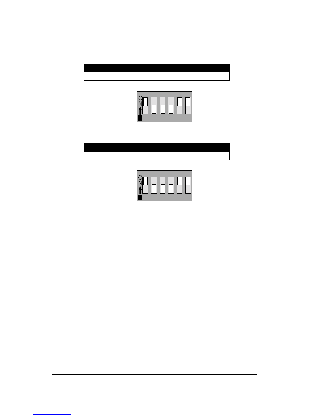
The Application of W83781D also controls the fan speed. The default of CPU
Fan, SYS1 Fan and SYS2 Fan is “Enable”.
♦ When you connect just only one CPU Fan -
If your system is using CPU Fan only, please disable the function of SYS1 Fan
and SYS2 Fan by the following steps:
1. When you complete the setup and reboot the system, the system will alarm with an
warning “ beep“ sound. Please click the “ START” "” PROGRAM” buttons and
select the “ Hardware Doctor” , the system will display the message as next page:

B683/B680
40
2. Click the “ Disable” of the warning icon of Fan 3, then it shows the
warning icon of Fan 2. You just click the “ Disable” icon as previous
step. Then “ Save” and “ Exit” .
The correct setup is completed.
B683/B680
41
How to install the CPU
Prepare the motherboard by installing the supplied Slot 1 CPU, then install
the CPU according to the instructions supplied. Complete the processor
installation by installing the supplied heat-sink support, and connecting the heat
sink power cable to the motherboard connector.
Referential Steps of installing the Slot 1 CPU
This part is only for CPU installation. Regarding to the heat-sink part, please
refer the instructions supplied.
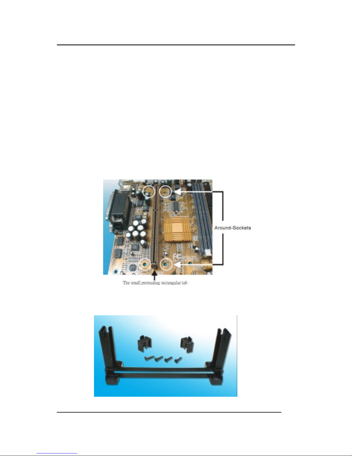
1. Inspect the area around Slot1, verify the position of four around-sockets,
and then locate the small protruding rectangular tab on the side of Slot1
(see diagram).
2. Examine the CPU Retention and attachments. There are three sets of
attachments: 1. The stand itself. 2. The CPU locking caps (two). 3. The
plastic screws (four).

B683/B680
42
3. Once the above two steps have been completed, slot the CPU Retention
into Slot1. Pull up the CPU stays on both side of the CPU Retention so
they are horizontal, at an angle of 90°. Then the side of the CPU
Retention with no mark on it and the side of Slot1 with the small
rectangular tab should be on the same side.
4. Ensure that the CPU Retention has been slotted all the way in, then screw
the four plastic screws into the sockets on each side of Slot1 to make sure
that the CPU Retention is fixed firmly in position.
! The CPU Retention has to
go in a particular direction.
Make sure that it is the right wa
y
round before slotting it in. Do
not force it in, otherwise you ma
y
damage the motherboard and
CPU Retention.

B683/B680
43
5. Slide the CPU slowly into Slot1 along the two sides of the CPU
Retention.
Note: Some Slot 1 processors with different packing maybe need the caps to let
them be fixed. So if it need the caps during installing Slot 1 CPU, please
follow this step: “ Fix the CPU locking caps onto the two ends of the
CPU stays ”.
6. Connect the CPU Fan head to the CPU Fan connector on the
motherboard, and make sure that the CPU has been fixed firmly onto
the motherboard. You have now completed assembly.

B683/B680
44
SLOT 1 CPU Disassembly/Replacement Procedures
1. Move the protruding part on top of the CPU locking caps gently outwards,
so that the locking caps come off.
2. Pull the CPU Fan connector off the motherboard, and then gently pull the
CPU out from Slot1.
3. If you need to install another CPU, follow the instructions for Slot1 CPU
installation given above.
CPU & Power Supply Fan Connectors (3-pin FanPWR)
These connector support cooling fans of 500mAMP (6WATT) or less. Orientate the fans so that the heat sink fins allow airflow to go across the onboard
heat sink(s) instead of expansion slots. Depending on the fan manufacturer, the
wiring and plug may be different. The red wire should be positive, while the
black should be ground. Connect the fan’ s plug to the board taking into
consideration the polarity of this connector.
The CPU and motherboard will overheat if there is no airflow
across the CPU and onboard heatsinks. Damage may occur to the
motherboard and the CPU fan if these pins are incorrectly used.
The “Rotation” signal is to be used only by a specially designed fan with
rotation signal.
!

B683/B680
45
 Loading...