

Procom Heating MNSD200TBA-BB, MNSD300TBA-BB, MNSD300TBA, MNSD100TBA, MNSD200TBA User Manual
...Page 1
VENT-FREE GAS WALL
US
HEATER
OWNER’S OPERATION AND
INSTALLATION MANUAL
BLUE FLAME MODELS
MNSD100TBA, MNSD200TBA
MNSD300TBA, MNSD100HBA
MNSD200TBA-BB
MNSD300TBA-BB
®
WARNING: If the information in this manual is not
followed exactly, a re or explosion may result causing
property damage, personal injury or loss of life.
— Do not store or use gasoline or other ammable va-
pors and liquids in the vicinity of this or any other
appliance.
— WHAT TO DO IF YOU SMELL GAS
• Do not try to light any appliance.
• Do not touch any electrical switch; do not use any
phone in your building.
•
Immediately call your gas supplier from a neighbor’s
phone. Follow the gas supplier’s instructions.
• If you cannot reach your gas supplier, call the re
department.
—
Installation and service must be performed by a qualied installer, service agency or the gas supplier.
WARNING: This appliance is equipped for Natural and
Propane gas. Field conversion is not permitted other than
between natural or propane gases.
Questions, problems, missing parts? Before returning to your retailer, call
our customer service department at 1-866-573-0674, 7:30 am - 4:15 pm CST,
Monday through Friday or email customerservice@usaprocom.com
Page 2
TABLE OF CONTENTS
Safety ........................................................ 3
Specications ............................................ 4
Qualied Installing Agency ........................ 5
Product Features ....................................... 5
Local Codes............................................... 6
Product Identication ................................. 6
Unpacking.................................................. 6
Water Vapor: A By-Product Of
Unvented Room Heaters ..................... 7
Air For Combustion and Ventilation ........... 7
Installation ................................................. 9
Operation ................................................. 19
Electrical Connection ............................... 22
Electrical Wiring ....................................... 22
Inspecting Heater .................................... 23
Care And Maintenance ............................ 24
Troubleshooting ....................................... 25
Service Hints ........................................... 28
Technical Service..................................... 28
Replacement Parts .................................. 29
Accessories ............................................. 29
Parts ........................................................ 30
Warranty .................................................. 36
SAVE THIS BOOK
INSTALLER: Leave this manual with the appliance.
CONSUMER: Retain this manual for future reference.
This is an unvented gas-red heater. It uses air (oxygen)
from the room in which it is installed. Provisions for ad-
equate combustion and ventilation air must be provided.
Refer to Air For Combustion and Ventilation section on
page 7 of this manual.
WARNING: Improper installation, adjustment, al-
teration, service or maintenance can cause injury or
property damage. Refer to this manual for correct installation and operational procedures. For assistance
or additional information consult a qualied installer,
service agency or the gas supplier.
This appliance may be installed in an aftermarket,* permanently located, manufactured (mobile) home, where
not prohibited by local codes.
This appliance is only for use with propane or natural
gas. Field conversion by any other means including the
use of a kit is not permitted.
* Aftermarket: Completion of sale, not for purpose of resale, from the manufacturer.
PROCOM HEATING, INC. PATENT INFORMATION
This product may be covered by one or more of the following United States patents:
8,915,239 8,851,065 8,764,436 8,757,202 8,757,139 8,752,541 8,568,136
8,545,216 8,517,718 8,516,878 8,506,290 8,465,277 8,317,511 8,297,968
8,281,781 8,241,034 8,235,708 8,152,515 8,011,920 7,967,006 7,967,007
7,654,820 7,730,765 7,677,236 7,607,426 7,434,447
www.usaprocom.com
200213-01B2
Page 3
SAFETY
IMPORTANT: Read this owner’s
manual carefully and completely
before trying to assemble, operate, or service this heater.
Improper use of this heater can
cause serious injury or death
from burns, fire, explosion,
electrical shock and carbon
monoxide poisoning.
Only a qualied installer, service
agent, or local gas supplier may
install and service this product.
WARNING: Keep the appli-
ance area clear and free from
combustible materials, gasoline,
and other ammable vapors and
liquids.
WARNING: This appliance
can be used with propane or
natural gas. It is shipped from
the factory adjusted for use with
propane.
This appliance is only for use
with the type of gas indicated on
the rating plate. This appliance
is not convertible for use with
other gases.
DANGER: Carbon monoxide
poisoning may lead to death!
CARBON MONOXIDE POISONING: Early
signs of carbon monoxide poisoning resemble
the u, with headaches, dizziness or nausea.
If you have these signs, the heater may not be
working properly. Get fresh air at once! Have
heater serviced. Some people are more affected by carbon monoxide than others. These
include pregnant women, people with heart or
lung disease or anemia, those under the inuence of alcohol and those at high altitudes.
NATURAL AND PROPANE/LP GAS: Natural
and Propane/LP gas are odorless. An odormaking agent is added to the gas. The odor
helps you detect a gas leak. However, the
odor added to the gas can fade. Gas may be
present even though no odor exists.
WARNING: Any change to
this heater or its controls can
be dangerous.
WARNING: Do not use any
accessories not approved for
use with this heater.
WARNING: Carefully supervise young children when they
are in the room with the heater.
WARNING: Make sure grill
guard is in place before running
heater.
WARNING: Due to high temperatures, the appliance should
be located out of trafc and away
from furniture and draperies.
WARNING: Heater becomes
very hot when running. Keep
children and adults away from
hot surfaces to avoid burns or
clothing ignition. Heater will remain hot for a time after shutoff.
Allow surfaces to cool before
touching.
WARNING: Do not place
clothing or other flammable
material on or near the appli-
ance. Never place any objects
in the heater.
www.usaprocom.com
3200213-01B
Page 4
SAFETY
1. Do not place Propane/LP supply tank(s)
inside any structure. Propane/LP supply
tank(s) must be placed outdoors.
2. Heaters with a maximum input over
6,000 Btu/Hr shall not be installed in a
bathroom. Heaters with a maximum input
over 10,000 Btu/Hr shall not be installed
in a bedroom.
3. This heater needs fresh air ventilation to
run properly. This heater has an Oxygen
Depletion Sensing (ODS) safety shutoff
system. The ODS shuts down the heater
if not enough fresh air is available. See
Air for Combustion and Ventilation, pages
7 and 8. If heater keeps shutting off, see
Troubleshooting, page 25.
4. Keep all air openings in front and bottom
of heater clear and free of debris. This will
ensure enough air for proper combustion.
5. If heater shuts off, do not relight until you
have provided fresh, outside air. If heater
keeps shutting off, have it serviced.
6. Do not run heater:
• Where ammable liquids or vapors are
used or stored.
• Under dusty conditions.
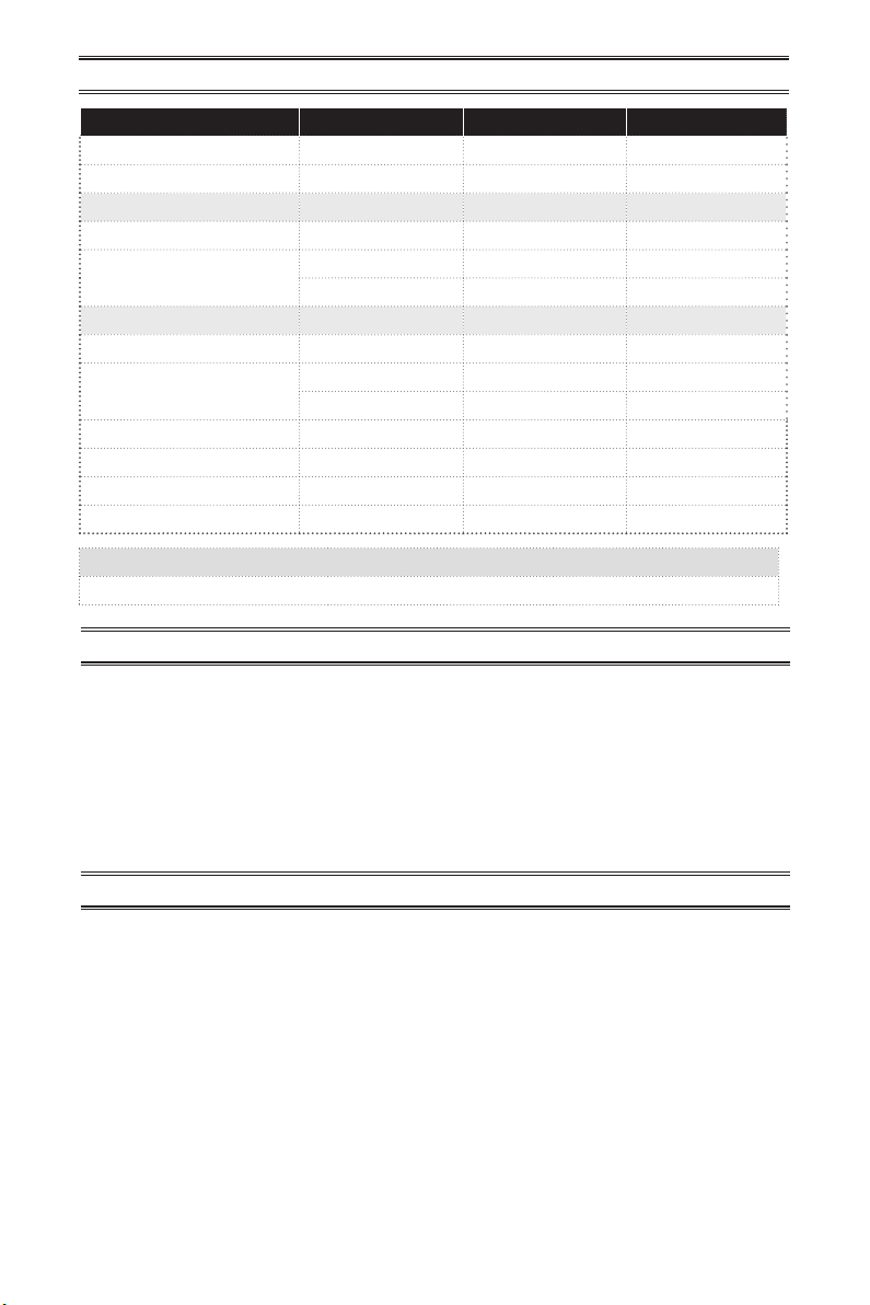
SPECIFICATIONS
7. Before using furniture polish, wax, carpet
cleaner, or similar products, turn heater off.
If heated, the vapors from these products
may create a white powder residue within
burner box or on adjacent walls or furniture.
8. Manual Control Models Only: Always
run heater with control knob at PILOT/
IGN, LOW (1) or HIGH (5) locked positions.
Never set control knob between locked
positions. Poor combustion and higher
levels of carbon monoxide may result.
9. Do not use heater if any part has been
under water. Immediately call a qualied
service technician to inspect the room
heater and to replace any part of the
control system and any gas control which
has been under water.
10. Turn off and unplug heater and let cool
before servicing. Only a qualied service
person should service and repair heater.
11. Operating heater above elevations of
4,500 feet could cause pilot outage.
12. To prevent performance problems, do
not use propane/LP fuel tank of less than
100 lbs. capacity.
MODEL MNSD100TBA MNSD200TBA MNSD300TBA
BTU (available) 10,000 20,000 30,000
Ignition Electric Piezo Electric Piezo Electric Piezo
Gas Type Using Natural Gas Using Natural Gas Using Natural Gas
Pressure Regulator Setting 4" W.C. 4" W.C. 4" W.C.
Inlet Gas Pressure*
(inches of water)
Gas Type Using Propane Gas Using Propane Gas Using Propane Gas
Pressure Regulator Setting 9.5" W.C. 9.5" W.C. 9.5" W.C.
Inlet Gas Pressure*
(inches of water)
Heater Dimensions (HxWxD)
Carton Dimensions (HxWxD)
Heater Weight 14.6 lbs 22.2 lbs 28.1 lbs
Shipping Weight 17.6 lbs 26.2 lbs 33.1 lbs
Maximum 9" Maximum 9" Maximum 9"
Minimum 5" Minimum 5" Minimum 5"
Maximum 14" Maximum 14" Maximum 14"
Minimum 11" Minimum 11" Minimum 11"
19 1/8" × 14 1/8" × 6 3/8"
22 ×16 3/4" × 8 1/8"
www.usaprocom.com
23 1/2" × 19 1/4" × 8" 23 1/2" x 26 5/8" x 8"
25 3/4" × 21 3/4" × 9 1/4"
25 3/4" x 28 1/2" x 9 1/4"
200213-01B4
Page 5
SPECIFICATIONS
MODEL MNSD100HBA MNSD200TBA-BB MNSD300TBA-BB
BTU (available) 10,000 20,000 30,000
Ignition Electric Piezo Electric Piezo Electric Piezo
Gas Type Using Natural Gas Using Natural Gas Using Natural Gas
Pressure Regulator Setting 4" W.C. 4" W.C. 4" W.C.
Inlet Gas Pressure*
(inches of water)
Gas Type
Pressure Regulator Setting 9.5" W.C. 9.5" W.C. 9.5" W.C.
Inlet Gas Pressure*
(inches of water)
Heater Dimensions (HxWxD)
Carton Dimensions (HxWxD)
Heater Weight 14.1 lbs 25.1 lbs 31 lbs
Shipping Weight 17.1 lbs 29.1 lbs 36 lbs
Electrical Requirement for Blower Kit (if equipped)
Maximum 9" Maximum 9" Maximum 9"
Minimum 5" Minimum 5" Minimum 5"
Using Propane Gas
Maximum 14" Maximum 14" Maximum 14"
Minimum 11" Minimum 11" Minimum 11"
19 1/8" × 14 1/8" × 6 3/8"
22 ×16 3/4" × 8 1/8"
Voltage • 120 VAC, 60 Hz
Using Propane Gas
23 1/2" × 19 1/4" × 8" 23 1/2" x 26 5/8" x 8"
25 3/4" × 21 3/4" × 9 1/4" 25 3/4" x 28 1/2" x 9 1/4"
Using Propane Gas
QUALIFIED INSTALLING AGENCY
Only a qualied agency should install and
replace gas piping, gas utilization equipment
or accessories, and repair and equipment servicing. The term “qualied agency” means any
individual, rm, corporation, or company that
either in person or through a representative
is engaged in and is responsible for:
PRODUCT FEATURES
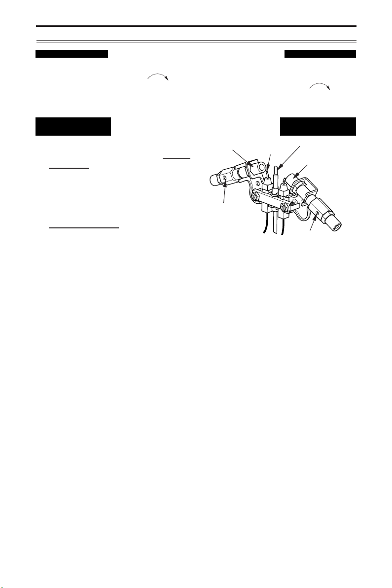
SAFETY PILOT
This heater has a pilot with an Oxygen Depletion Sensing (ODS) safety shutoff system. The
ODS/pilot shuts off the heater if there is not
enough fresh air.
2 GAS OPTIONS AVAILABLE
Your heater is equipped to operate on either
Propane/LP or Natural gas. The heater is
shipped from the factory ready for connecting to Propane/LP. The heater can easily be
changed to Natural gas by having your qualied installer follow the instructions on page
14 and the markings on the heater.
www.usaprocom.com
a) Installing, testing, or replacing gas piping
or
b) Connecting, installing, testing, repairing,
or servicing equipment; that is experienced
in such work; that is familiar with all precautions required; and that has complied with
all the requirement of the authority having
jurisdiction.
THERMOSTATIC CONTROL
(Thermostat Models Only)
These heaters have a control valve with a
thermostat sensing bulb. This results in the
greatest heater comfort and may result in
lower gas bills.
5200213-01B
Page 6
LOCAL CODES
Install and use heater with care. Follow all
local codes. In the absence of local codes,
use the latest edition of The National Fuel
Gas Code, ANSI Z223.1/NFPA 54*.
*Available from:
American National Standards Institute, Inc.
25 West 43rd Street
New York, NY 10036
National Fire Protection Association, Inc.
1 Batterymarch Park
Quincy, MA 02269-9101
PRODUCT IDENTIFICATION
State of Massachusetts: The installation
must be made by a licensed plumber or
gas tter in the Commonwealth of Massachusetts.
Sellers of unvented propane or natural
gas-red supplemental room heaters shall
provide to each purchaser a copy of 527
CMR 30 upon sale of the unit.
In the State of Massachusetts the gas
cock must be a T-handle type. The State
of Massachusetts requires that a exible
appliance connector cannot exceed three
feet in length.
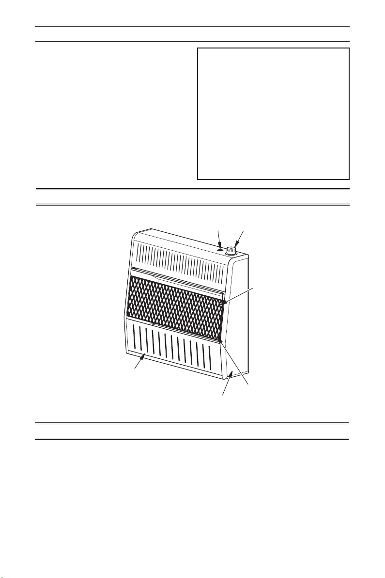
Ignitor
Button
Control
Knob
Grill
Front
Panel
Figure 1 - Vent-Free Gas Heater
UNPACKING
1. Remove heater from carton.
2. Remove all protective packaging applied
to heater for shipping
www.usaprocom.com
Burner
Heater Cabinet
3. Check heater for any shipping damage. If
heater is damaged, promptly inform dealer
where you bought heater.
200213-01B6
Page 7
WATER VAPOR: A BY-PRODUCT OF
UNVENTED ROOM HEATERS
Water vapor is a by-product of gas combustion. An unvented room heater produces approximately one (1) ounce (30 mL) of water for
every 1,000 BTUs (0.3 KWs) of gas input per
hour. Unvented room heaters are recommended
as supplemental heat (a room) rather than a
primary heat source (an entire house). In most
supplemental heat applications, the water vapor
does not create a problem. In most applications,
the water vapor enhances the low humidity
atmosphere experienced during cold weather.
AIR FOR COMBUSTION AND VENTILATION
WARNING: This heater shall
not be installed in a conned
space or unusually tight construction unless provisions are
provided for adequate combustion and ventilation air. Read the
following instructions to insure
proper fresh air for this and other
fuel-burning appliances in your
home.
Today’s homes are built more energy efcient
than ever. New materials, increased insulation
and new construction methods help reduce
heat loss in homes. Home owners weather
strip and caulk around windows and doors
to keep the cold air out and the warm air in.
During heating months, home owners want
their homes as airtight as possible.
While it is good to make your home energy
efcient, your home needs to breathe. Fresh
air must enter your home. All fuel-burning appliances need fresh air for proper combustion
and ventilation.
Exhaust fans, replaces, clothes dryers and
fuel burning appliances draw air from the
house to operate. You must provide adequate
fresh air for these appliances. This will insure
proper venting of vented fuel-burning appliances.
The following steps will help ensure that water
vapor does not become a problem.
1. Be sure the heater is sized properly for the
application, including ample combustion
air and circulation air.
2. If high humidity is experienced, a dehumidier may be used to help lower the
water vapor content of the air.
3. Do not use an unvented room heater as
the primary heat source.
WARNING: This heater shall
not be installed in a room or
space unless the required vol-
ume of indoor combustion air
is provided by the method described in the National Fuel Gas
Code, ANSI Z223.1/NFPA 54, the
International Fuel Gas Code, or
applicable local codes.
WARNING: If the area in which
the heater may be operated does
not meet the required volume for
indoor combustion air, combustion and ventilation air shall be
provided by one of the methods
described in the National Fuel
Gas Code, ANSI Z223.1/NFPA 54,
the International Fuel Gas Code,
or applicable local codes.
www.usaprocom.com
7200213-01B
Page 8
AIR FOR COMBUSTION AND VENTILATION
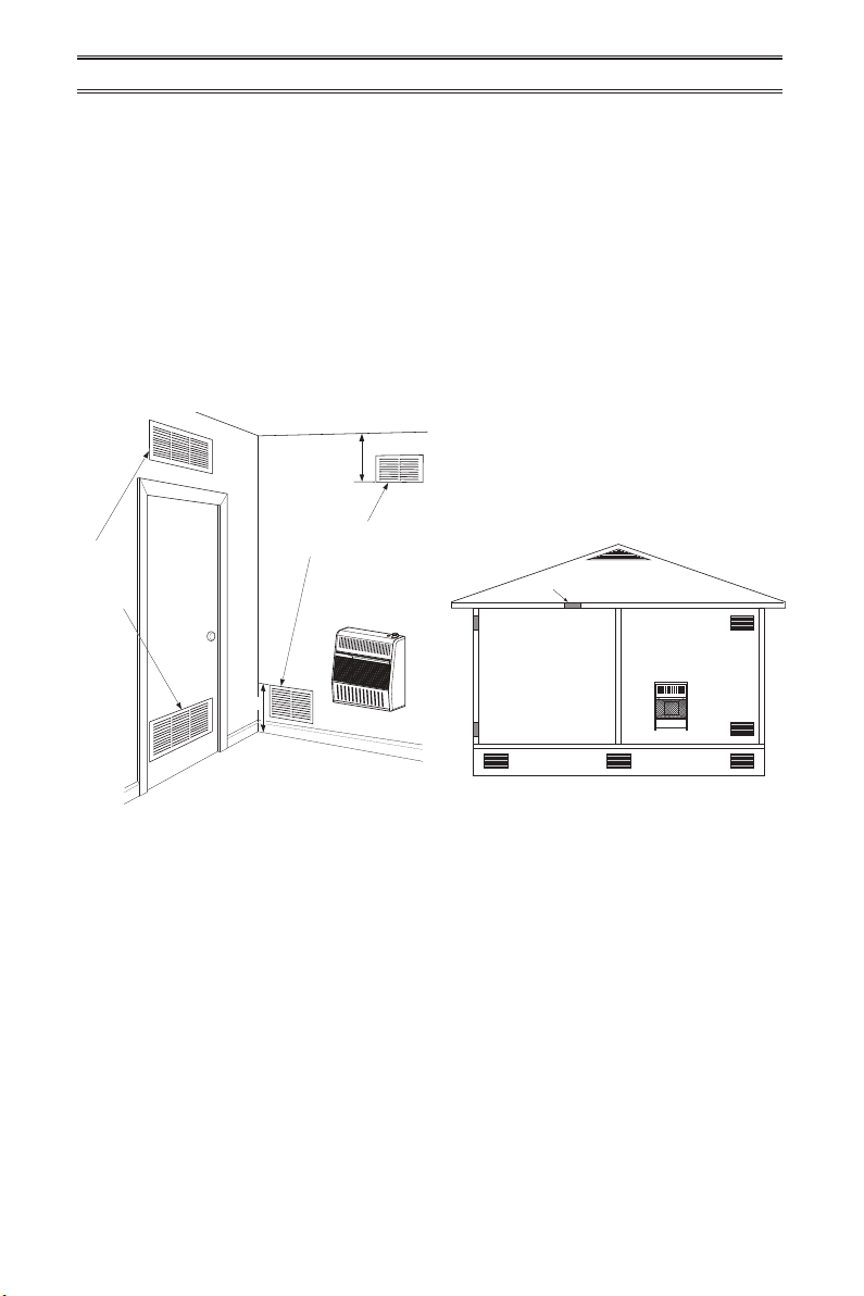
Ventilation
VENTILATION AIR
Ventilation Air From Inside Building
This fresh air would come from an adjoining
unconned space. When ventilating to an
adjoining unconned space, you must provide
two permanent openings: one within 12" of the
ceiling and one within 12" of the oor on the
wall connecting the two spaces (see options
1 and 2, Figure 2). You can also remove door
into adjoining room (see option 3, Figure 2).
Follow the National Fuel Gas Code, ANSI
Z223.1/NFPA 54, Air for Combustion and
Ventilation for required size of ventilation
grills or ducts.
12"
Ventilation Grills
Into Adjoining Room,
Grills into
Adjoining
Room,
Option 1
Or
Remove
Door into
Adjoining
Room,
Option 3
12"
Figure 2 - Ventilation Air from Inside
Building
Note: Base not included. Not for use in bedrooms or bathrooms.
Option 2
Ventilation Air From Outdoors
Provide extra fresh air by using ventilation
grills or ducts. You must provide two permanent openings: one within 12" of the ceiling
and one within 12" of the oor. Connect these
items directly to the outdoors or spaces open
to the outdoors. These spaces include attics
and crawl spaces. Follow the National Fuel
Gas Code, ANSI Z223.1/NFPA 54, Air for
Combustion and Ventilation for required size
of ventilation grills or ducts.
IMPORTANT: Do not provide openings
for inlet or outlet air into attic if attic has a
thermostat-controlled power vent. Heated air
entering the attic will activate the power vent.
Rework worksheet, adding the space of the
adjoining unconned space. The combined
spaces must have enough fresh air to supply
all appliances in both spaces.
Ventilated
Attic
Crawl Space
Ventilated
To Attic
To
Crawl
Space
Outlet
Air
Inlet
Air
Outlet
Air
Inlet Air
Figure 3 - Ventilation Air from Outdoors
www.usaprocom.com
200213-01B8
Page 9
INSTALLATION
NOTICE: This heater is intended
for use as supplemental heat.
Use this heater along with your
primary heating system. Do not
install this heater as your primary heat source. If you have a
central heating system, you may
run system’s circulating blower
while using heater. This will help
circulate the heat throughout the
house. In the event of a power
outage, you can use this heater
as your primary heat source.
CAUTION: When installing
heater in a home garage
• heater pilot and burner must
be at least 18" above oor
• locate heater where moving
vehicle will not hit it
WARNING: A qualied service person must install heater.
Follow all local codes.
WARNING: Never install the
heater
• 10,000 Btu/Hr in a bathroom
• over 10,000 Btu/Hr in a bedroom or bathroom (Check local
codes.)
• in a recreational vehicle
• where curtains, furniture,
clothing, or other ammable
objects are less than 36" from
the front, top, or sides of the
heater
• in high trafc areas
• in windy or drafty areas
CAUTION: This heater creates warm air currents. These
currents move heat to wall surfaces next to heater. Installing
heater next to vinyl or cloth wall
coverings or operating heater
where impurities (such as tobacco smoke, aromatic candles,
cleaning uids, oil or kerosene
lamps, etc.) in the air exist, may
cause walls to discolor.
IMPORTANT: Vent-free heaters add moisture
to the air. Although this is benecial, installing
heater in rooms without enough ventilation air
may cause mildew to form too much moisture.
See Air for Combustion and Ventilation, pages
7 and 8.
www.usaprocom.com
9200213-01B
Page 10
CEILING
2" Minimum to Top Surface of Carpeting,
INSTALLATION
CHECK GAS TYPE
Be sure your gas supply is right for your heater. Otherwise, call dealer where you bought
the heater for proper type heater.
CLEARANCES TO
COMBUSTIBLES
Carefully follow the instructions below. This
heater is a freestanding unit designed to be
mounted on a wall or set on a base.
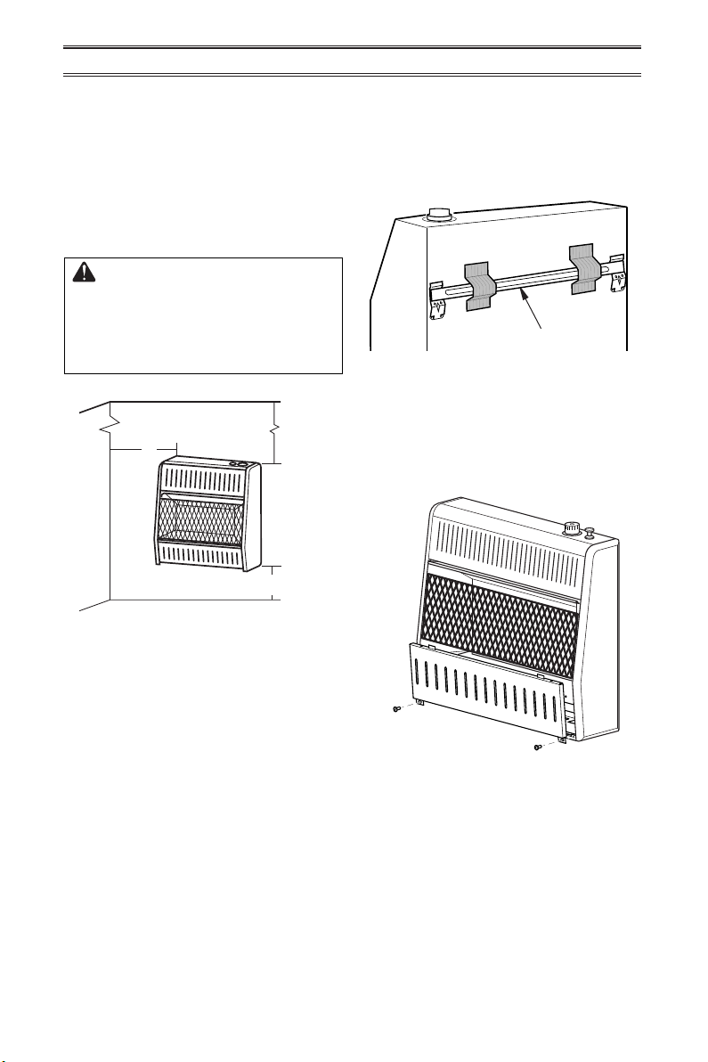
WARNING: Maintain the
minimum clearances shown in
Figure 4. If you can, provide
greater clearances from oor,
ceiling, and joining wall.
36"
6"
Minimum
From
Sides of
Heater
Left
Side
Tile or Other Combustible Material
FLOOR
Figure 4 - Mounting Clearances as
Viewed From Front of Heater
Minimum
Right
Side
FASTENING HEATER TO WALL
Mounting Bracket
The mounting bracket is located on back panel
of heater (see Figure 5). It has been taped
there for shipping. Remove mounting bracket
from back panel.
Mounting Bracket
Figure 5 - Mounting Bracket Location
Removing Front Panel of Heater
1. Remove two screws near bottom corners
of lower front panel.
2. Pull bottom of lower front panel forward,
then down (see Figure 6).
LOCATING HEATER
This heater is designed to be mounted on a
wall. For convenience and efciency, install
heater:
1. Where there is easy access for operation,
inspection, and service.
2. In the coldest part of room.
www.usaprocom.com
Figure 6 - Removing Front Panel Of
Heater
200213-01B10
Page 11
INSTALLATION
Methods For Attaching Mounting
Bracket To Wall
Use only the last hole on each end of mounting bracket to attach bracket to wall. Attach
mounting bracket to a wall only in one of two
ways:
1. Attaching to wall stud: This method pro-
vides the strongest hold. Insert mounting
screws through mounting bracket and into
wall studs.
2. Attaching to wall anchor: This method
allows you to attach mounting bracket to
hollow walls (wall areas between studs)
or to solid walls (concrete or masonry).
Decide which method better suits your needs.
Either method will provide a secure hold for
the mounting bracket.
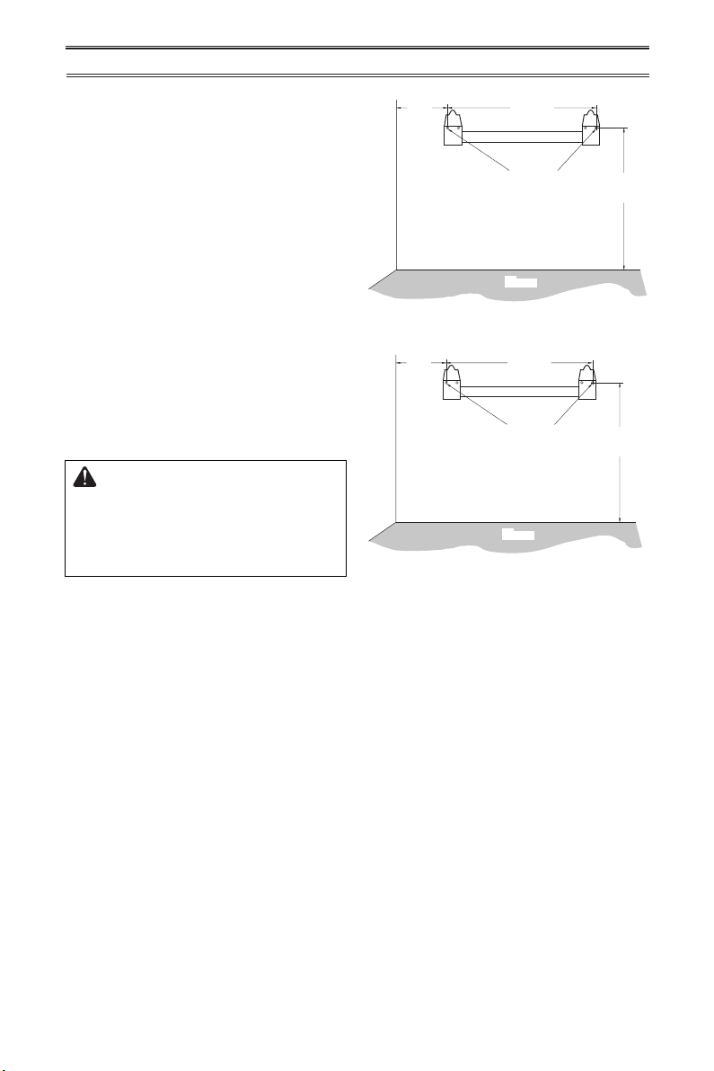
Marking Screw Locations
1. Tape mounting bracket to wall where
heater will be located. Make sure mounting bracket is level.
WARNING: Maintain minimum
clearances shown in Figure
4, page 10. If you can, provide
greater clearances from oor and
joining wall.
2. Mark screw locations on wall (see Figure
7).
Note: Mark only last hole on each end of
mounting bracket. Insert mounting screws
through these holes only.
3. Remove tape and mounting bracket from
wall.
3
/4"
6
Min.
Only Insert Mounting
Screws Through Last
Adjoining Wall
121/8"
Hole On Each End
Floor
141/2"
Min.
Models: MNSD100TBA & MNSD100HBA
10 5/8"
Min.
Only Insert Mounting
Screws Through Last
Hole On Each End
17
3
/8"
1
18
/2"
Min.
Adjoining Wall
Floor
MNSD200TBA, MNSD300TBA
MNSD200TBA-BB, MNSD300TBA-BB
Figure 7 - Mounting Bracket Clearances
Attaching Mounting Bracket To Wall
Note: Wall anchors, mounting screws, and
spacers are in hardware package. The hardware package is provided with heater.
Attaching to Wall Stud Method
For attaching mounting bracket to wall studs:
1. Drill holes at marked locations using 9/64"
drill bit.
2. Place mounting bracket onto wall. Line
up last hole on each end of bracket with
holes drilled in wall.
3. Insert mounting screws through bracket
and into wall studs.
4. Tighten screws until mounting bracket is
rmly fastened to wall studs.
Models:
www.usaprocom.com
11200213-01B
Page 12
Attaching to Wall Anchor Method
For attaching mounting bracket to hollow
walls (wall areas between studs) or solid walls
(concrete or masonry):
1. Drill holes at marked locations using
5/16" drill bit. For solid walls (concrete or
masonry), drill at least 1" deep.
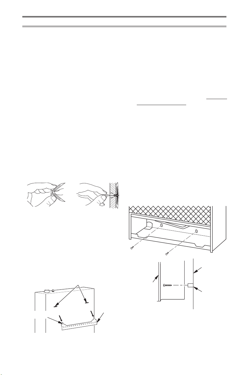
2. Fold wall anchor as shown in Figure 8.
3. Insert wall anchor (wings rst) into hole.
Tap anchor ush to wall.
4. For thin walls (1/2" or less), insert red key
into wall anchor. Push red key to “pop”
open anchor wings (see Figure 9).
IMPORTANT: Do not hammer anchor key! For
thick walls (over 1/2" thick) or solid walls, do
not pop open wings.
5. Place mounting bracket onto wall. Line up
last hole on each end of bracket with wall
anchors.
6. Insert mounting screws through bracket
and into wall anchors.
7. Tighten screws until mounting bracket is
rmly fastened to wall.
Installing Bottom Mounting Bracket
1. Install bottom bracket to heater bottom
with two screws. It may be more convenient to remove heater from wall bracket
to attach.
2. Place heater on wall mounting bracket.
3. Mark screw locations on wall.
4. Remove heater from mounting bracket.
5. If installing bottom mounting screws into
hollow or solid wall, install wall anchors.
Follow steps 1 through 4 under Attaching
To Wall Anchor Method. If installing bottom
mounting screw into wall stud, drill holes at
marked locations using 9/64" drill bit.
6. Replace heater onto mounting bracket.
7. Place spacers between bottom mounting
holes and wall anchor or drilled hole.
8. Hold spacer in place with one hand. With
other hand, insert mounting screw though
bottom mounting hole and spacer. Place
tip of screw in opening of wall anchor or
drilled hole.
9. Tighten both screws until heater is rmly
secured to wall. Do not over tighten.
Note: Do not replace front panel at this time.
Replace front panel after making gas connections and checking for leaks.
Figure 8 - Folding
Anchor
Figure 9 - Popping
Open Anchor Wings
For Thin Walls
Placing Heater On Mounting
Bracket
1. Locate two horizontal slots on back panel
of heater (see Figure 10).
2. Place heater onto mounting bracket. Slide
horizontal slots onto stand-out tabs on
mounting bracket.
Horizontal Slots
Mounting
Bracket
(attached
Stand-Out Tab
to wall)
Figure 10 - Mounting Heater Onto
Mounting Bracket
www.usaprocom.com
Front View
Wall
Heater
Spacer
Side View
Figure 11 - Installing Bottom Mounting
Screws
200213-01B12
Page 13
INSTALLATION
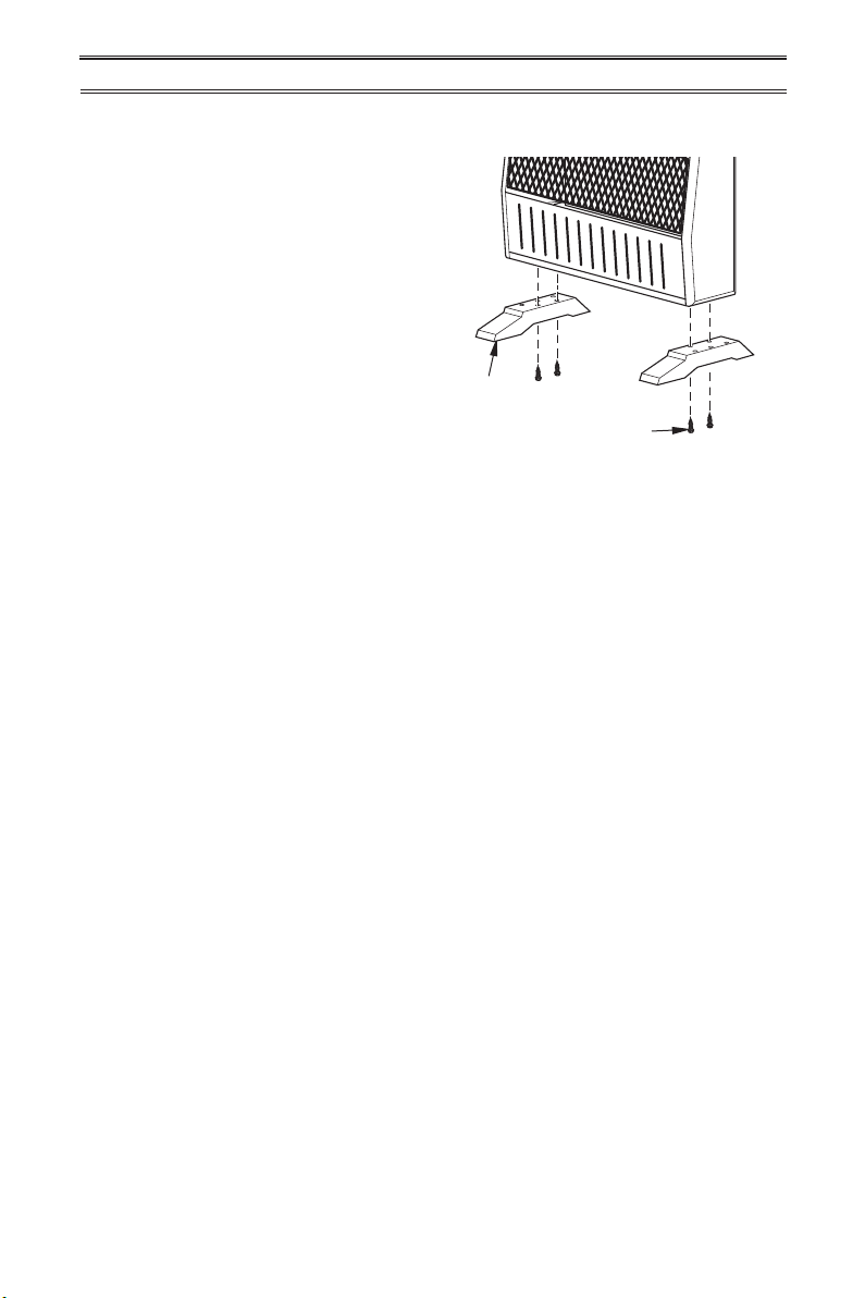
INSTALLATION OF BASE STAND
(If Equipped)
Before installing heater to base, please make
sure you have a hardware packet that contains the following items:
2 - Base Feet
4 - Sheet Metal Screws
1. Carefully lay heater on its back on a table
with the bottom of the heater extending
outside the table edge.
2. Attach base feet to heater using sheet
metal screws.
Base Feet
Sheet Metal Screws
Figure 12 - Installing Base Feet
www.usaprocom.com
13200213-01B
Page 14
INSTALLATION
GAS SELECTION
This appliance is factory
preset for propane/LP gas.
No changes are required for
connecting to propane/LP.
Only a qualied installer or service
technician can perform gas selection and connecting to gas supply.
CAUTION: Two gas line in-
stallations at the same time are
prohibited.
CAUTION: To avoid gas leakage for the gas not being used at
the inlet of regulator, a qualied
installer or service technician
must use supplied cap.
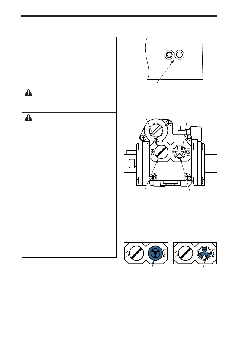
You will notice a color coded
plunger on the inside of the regulator. This is normal. When the in-
let connection tting is inserted
and tightened, this plunger will
be pushed back by the tting
making all of the adjustments
for the gas being supplied. DO
NOT REMOVE THE PLUNGER.
The regulator will not work.
The inlet regulator is color coded
for identication of the correct
gas type. Blue is for propane (LP
gas) and yellow is for natural gas.
INLET GAS PRESSURE
MAX 1/2 PSIG (3.5 KPA)
NG
Gas Connection
Figure 13 - Back of Heater
Yellow Natural Gas
Plunger Underneath
Metal Cap
Insert Gas Fitting
for Natural Gas
Figure 14 - Gas Regulator
Blue Propane/LP Gas
Plunger Underneath
Dust Cover
Insert Gas Fitting
for Propane/LP Gas
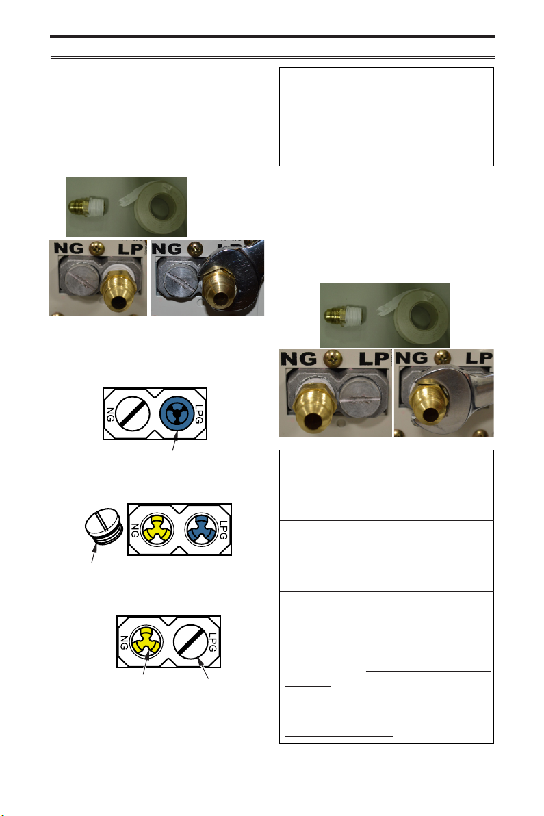
FOR PROPANE/LP GAS
INSTALLATION: BLUE
1. Remove blue dust cover.
LPG
Blue Dust Cover
www.usaprocom.com
DO NOT REMOVE
Blue Propane/LP
Plunger
Install Gas Fitting Here
200213-01B14
Page 15
INSTALLATION
2. Apply thread sealant to the threads on
the connection tting. While pushing in,
rotate the tting clockwise until the threads
engage the regulator. After the tting has
been hand tightened into the regulator
use a wrench to complete tightening of the
tting. Install additional tting to connect
to the house supply.
Fitting
supplied
by installer,
may vary.
FOR NATURAL GAS (NG)
INSTALLATION: YELLOW
1. Remove the blue dust cover from the
regulator.
Blue Dust Cover
2. Remove the metal cap installed over the
NG regulator inlet.
Use only the cap supplied on the
regulator. Do not use an off the
shelf pipe plug. This can damage
the plunger. The supplied regulator cap is designed so it will not
engage the unused gas type.
4. Apply thread sealant to the threads on
the connection tting. While pushing in,
rotate the tting clockwise until the threads
engage the regulator. After the tting has
been hand tightened into the regulator
use a wrench to complete tightening of the
tting. Install additional tting to connect
to the house supply.
DO NOT use an off the shelf 3/8"
NPT pipe plug. This will damage
the plungers located inside the
regulator.
Metal Cap
3. Install metal cap over LP/Propane regulator
inlet. This will keep debris out of regulator.
DO NOT REMOVE
Yellow Natural Gas Plunger
Install Gas Fitting Here
Metal Cap
www.usaprocom.com
DO NOT try to remove the plungers from inside the regulator. The
plunger will be pushed back as
the tting is installed.
Make sure the type of gas being
used is correct. Check to make
sure the connection tting is in
the correct inlet on the regulator. Refer to Connecting to Gas
Supply, page 16.
If you are using natural gas
and the pilot will not light, see
Troubleshooting, page 25.
15200213-01B
Page 16
INSTALLATION
CONNECTING TO GAS SUPPLY
WARNING: A qualied service technician must connect
heater to gas supply. Follow all
local codes.
WARNING: This appliance
requires a 3/8" NPT (National
Pipe Thread) inlet connection to
the pressure regulator.
WARNING: For natural gas,
Never connect heater to private
(non-utility) gas wells. This gas
is commonly known as wellhead
gas.
WARNING: Do not over-
tighten gas connections.
CAUTION: Use only new,
black iron or steel pipe. Internally tinned copper tubing may
be used in certain areas. Check
your local codes. Use pipe of
1/2" diameter or greater to allow
proper gas volume to heater. If
pipe is too small, undue loss of
pressure will occur.
CAUTION: For propane/
LP gas, never connect heater
directly to the gas supply. This
heater requires an external
regulator (not supplied). Install
the external regulator between
the heater and gas supply. Gas
supplier provides external regulator for natural gas. The installer
provides the external regulator
for propane/LP gas.
CAUTION: For natural gas,
check your gas line pressure
before connecting heater to gas
line. Gas line pressure must be
no greater than 9.5" of water. If
gas line pressure is higher, heater
regulator damage could occur.
CAUTION: Avoid damage to
regulator. Hold gas regulator
with wrench when connecting
into gas piping and/or ttings.
CAUTION: Use pipe joint
sealant that is resistant to gas
(Propane/LP or Natural Gas).
Before installing heater, make sure you have
the items listed below:
• external regulator for propane/LP unit only
(supplied by installer)
• piping (check local codes)
• sealant (resistant to natural gas and propane/LP gas)
• equipment shutoff valve*
• test gauge connection*
• sediment trap
• tee joint
• pipe wrench
• exible gas hose (check local codes)
* A CSA design-certied equipment shutoff
valve with 1/8" NPT tap is an acceptable alternative to test gauge connection. Purchase
the optional CSA design certied equipment
shutoff valve from your dealer.
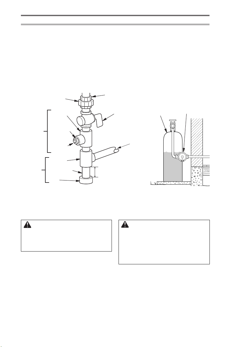
Typical Inlet Pipe Diameters
Use 3/8" black iron pipe or greater. Installation must include an equipment shutoff valve,
union, and plugged 1/8" NPT tap. Locate NPT
tap within reach for test gauge hook up. NPT
tap must be upstream from heater (see Figure
15, page 17).
IMPORTANT: Install an equipment shutoff
valve in an accessible location. The equipment shutoff valve is for turning on or shutting
off the gas to the appliance.
www.usaprocom.com
200213-01B16
Page 17
INSTALLATION
Apply pipe joint sealant lightly to male threads.
This will prevent excess sealant from going
into pipe. Excess sealant in pipe could result
in clogged heater valves.
For propane/LP gas, t
an external regulator. The external regulator
will reduce incoming gas pressure. You must
reduce incoming gas pressure to between 11"
and 14" of water. If you do not reduce incoming gas pressure, heater regulator damage
could occur. Install external regulator with
Ground
Joint Union
Test Gauge
Connection*
Sediment
Trap
* Purchase the optional CSA design-certied equipment
shutoff valve from your dealer.
he installer must supply
Tee Joint
Reducer
Bushing to
1/8" NPT
1/8" NPT
Plug Tap
Tee Joint
Pipe Nipple
Gap
Figure 15 - Gas Connection
3" Minimum
the vent pointing down as shown in Figure
16. Pointing the vent down protects it from
freezing rain or sleet.
Install sediment trap in supply line as shown
in Figure 15. Place sediment trap where it is
within reach for cleaning. Place sediment trap
where trapped matter is not likely to freeze.
A sediment trap traps moisture and contaminants. This keeps them from going into heater
controls. If sediment trap is not installed or is
installed wrong, heater may not run properly.
3/8" NPT
Pipe Nipple
Equipment
Shutoff Valve
Meter (4" W.C.
From External
Regulator (11" W.C.
to 14" W.C. Pressure)
Propane/LP
Supply Tank
Natural Gas
From Gas
to 9.5" W.C.
Pressure)
Propane/LP
Figure 16 - External Regulator
with Vent Pointing Down
External
Regulator with
Vent Pointing
Down
CHECKING GAS CONNECTIONS
WARNING: Test all gas piping
and connections for leaks after
installing or servicing. Correct
all leaks at once.
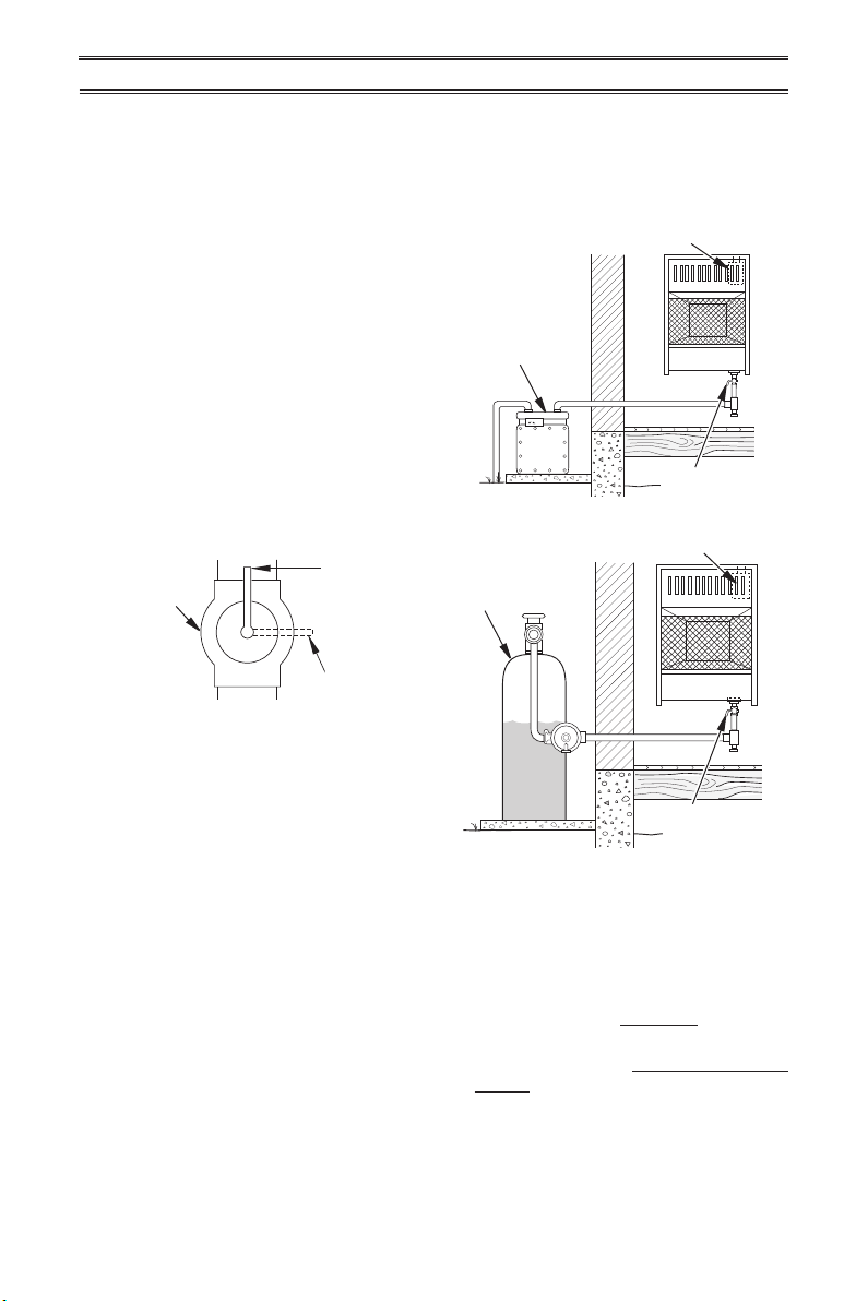
Pressure Testing Gas Supply Piping System
Test Pressures In Excess Of 1/2 PSIG (3.5 kPa)
1. Disconnect heater with its appliance main
gas valve (control valve) and equipment
shutoff valve from gas supply piping system. Pressures in excess of 1/2 PSIG will
damage heater regulator.
2. Cap off open end of gas pipe where equipment shutoff valve was connected.
www.usaprocom.com
WARNING: Never use an
open ame to check for a leak.
Apply a mixture of liquid soap
and water to all joints. If bubbles
form, there is a leak. Correct all
leaks at once.
3. Pressurize supply piping system by either
opening propane/LP supply tank valve
for propane/LP gas or opening main gas
valve located on or near gas meter for
natural gas or using compressed air.
17200213-01B
Page 18
INSTALLATION
4. Check all joints of gas supply piping system. Apply a noncorrosive leak detection
uid to all joints. If bubbles form, there may
be a leak.
Test Pressures Equal To or Less Than 1/2 PSIG (3.5 kPa)
1.
Close equipment shutoff valve (see Figure 17).
2. Pressurize supply piping system by either
opening propane/LP supply tank valve
for propane/LP gas or opening main gas
valve located on or near gas meter for
natural gas or using compressed air.
3. Check all joints from gas meter (natural
gas installations, see Figure 18) or from
propane/LP tank (propane/LP gas installations, see Figure 19) to equipment shutoff
valve. Apply a noncorrosive leak detection
uid to all joints. If bubbles form, there is
a leak.
4. Correct all leaks at once.
Equipment
Open
Shutoff Valve
Closed
Figure 17 - Equipment Shutoff Valve
5. Correct all leaks at once.
6. Reconnect heater and equipment shutoff
valve to gas supply. Check reconnected
ttings for leaks.
Gas Valve
Gas Meter
Equipment
Shutoff Valve
Figure 18 - Natural Gas Supply
Gas Valve
Propane/LP
Supply Tank
PRESSURE TESTING HEATER GAS CONNECTIONS
1.
Open equipment shutoff valve (see Fig-
ure 17).
2. For natural gas open main gas valve located on or near gas meter. For propane/
LP gas open propane/LP supply tank valve.
3. Make sure control knob of heater is in the
OFF position.
4. Check all joints from equipment shutoff
valve to control valve (see Figure 18 or
www.usaprocom.com
Equipment
Shutoff Valve
Figure 19 - Propane/LP Fuel Supply
19).
Apply a noncorrosive leak detection
uid to all joints.
Bubbles forming show a
leak.
5. Correct all leaks at once.
6. Light heater (see Operation, page 19).
Check all other internal joints for leaks.
7. Turn off heater (see To Turn Off Gas Ap-
pliance, page 20 or 21).
8. Replace lower front panel.
200213-01B18
Page 19
OPERATION
FOR YOUR SAFETY READ BEFORE LIGHTING
WARNING: If you do not follow these instructions exactly, a
re or explosion may result causing property damage, personal
injury or loss of life.
A. This appliance has a pilot which must
be lighted by hand. When lighting the
pilot, follow these instructions exactly.
B. BEFORE LIGHTING smell all around the
appliance area for gas. Be sure to smell
next to the oor because some gas is
heavier than air and will settle on the oor.
WHAT TO DO IF YOU SMELL GAS
• Do not try to light any appliance.
• Do not touch any electric switch; do
MODELS MNSD100TBA, MNSD200TBA, MNSD300TBA,
MNSD200TBA-BB AND MNSD300TBA-BB
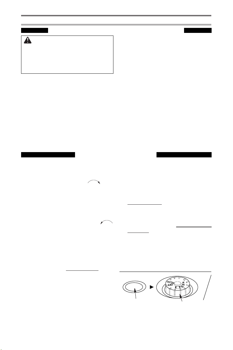
LIGHTING INSTRUCTIONS
1. STOP! Read the safety information above.
2. Make sure equipment shutoff valve is fully
open.
3. Turn control knob clockwise to the
OFF position.
4. Wait ve (5) minutes to clear out any air.
Then smell for gas, including near the
oor. If you smell gas, STOP! Follow "B"
in the safety information above. If you do
not smell gas, go to the next step.
5. Turn control knob counterclockwise
to the PILOT position. Press in control
knob for ve (5) seconds (see Figure 19).
Note: The rst time that the heater is oper-
ated after connecting the gas supply,the
control knob should be pressed for about
thirty (30) seconds. This will allow air to
bleed from the gas system. If pilot does
not stay lit, refer to Troubleshooting, pages
25 though 28. Also contact a qualied
service technician or gas supplier for
repairs. Until repairs are made, light pilot
with match.
• If control knob does not pop up when
released, contact a qualified service
technician or gas supplier for repairs.
not use any phone in your building.
• Immediately call your gas supplier
from a neighbor’s phone. Follow the
gas supplier’s instructions.
• If you cannot reach your gas supplier,
call the re department.
C. Use only your hand to push in or turn
the gas control knob. Never use tools.
If the knob will not push in or turn by
hand, don’t try to repair it, call a qualied
service technician. Force or attempted
repair may result in a re or explosion.
D. Do not use this appliance if any part
has been under water. Immediately call
a qualied service technician to inspect
the appliance and to replace any part of
the control system and any gas control
which has been under water.
6. With control knob pressed in, push
down and release ignitor button. This
will light pilot. The pilot is attached to
the front of burner. The pilot can be
seen through the grill. If needed, keep
pressing ignitor button until pilot lights.
Note: If pilot does not stay lit, refer to
Troubleshooting, pages 25 though 28.
Also contact a qualied service technician
or gas supplier for repairs. Until repairs
are made, light pilot with match. To light
pilot with match, see Manual Lighting
Procedure, page 21.
7. Keep control knob pressed in for 30
seconds after lighting pilot. After 30
seconds, release control knob. If control
knob does not pop up when released,
contact a qualied service technician or
gas supplier for repairs.
Ignitor Button
Figure 20 - Control Knob in the OFF
Control Knob
Position
www.usaprocom.com
19200213-01B
Page 20
OPERATION
Note: If pilot goes out, repeat steps 3
through 7. This heater has a safety interlock system. Wait one (1) minute before
lighting pilot again.
8. Turn control knob counterclockwise
to desired heating level. The main burner
should light. Set control knob to any heat
level between 1 and 5.
THERMOSTAT CONTROL OPERATION
The thermostatic control used on this model
differs from standard thermostats. Standard
thermostats simply turn the burner on and off.
The thermostat used on this heater senses
the room temperature. At times the room may
TO TURN OFF GAS TO APPLIANCE
Shutting Off Heater
Turn control knob clockwise to the
OFF position.
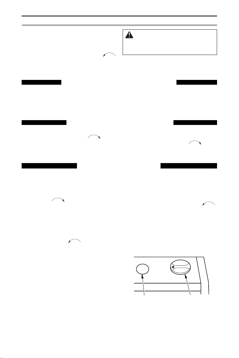
MODEL MNSD100HBA
LIGHTING INSTRUCTIONS
1. STOP! Read the safety information on
page 19.
2. Check that gas supply to heater is on.
3. Push in gas control knob slightly and turn
clockwise to the OFF position.
4. Wait ve (5) minutes to clear out any gas.
Then smell for gas, including near the
oor. If you smell gas, STOP! Follow "B"
in the safety information on on page 18. If
you do not smell gas, go to the next step.
5. Push in gas control knob slightly and turn
counterclockwise to "PILOT/IGN"
and press for ve (5) seconds
Note: The rst time that the heater is oper-
ated after connecting the gas supply, the
control knob should be pressed for about
thirty (30) seconds. This will allow air to
bleed from the gas system.
6. With control knob pressed in, push down
and release the ignitor button. This will
light pilot. If needed, keep pressing ignitor
button until pilot lights.
CAUTION: Do not try to ad-
just heating levels by using the
equipment shutoff valve.
exceed the set temperature. If so, the burner
will shut off. The burner will cycle back on
when room temperature drops below the set
temperature. The control knob can be set to
any comfort level between 1 and 5.
Shutting Off Burner Only (pilot
Turn control knob clockwise to the
PILOT position.
7. Keep control knob pressed for ten (10)
seconds after lighting pilot. If pilot goes
out, repeat steps 5, 6 and 7.
8. To select the desired heating level, partially press down the control knob slightly
and rotate counterclockwise .
Release the downward pressure on the
knob while continuing to turn until the knob
locks at the desired setting position. Do
not operate between locked positions. Set
control knob to desired heating position.
Note: Both HIGH and LOW are locked
positions. You must press in control knob
before turning it from these positions.
Ignitor Button Control Knob
Figure 21 - Control Knob in the OFF
stays lit )
OFF
PILOT/IGN
Position
LOW
HIGH
www.usaprocom.com
200213-01B20
Page 21
OPERATION
TO TURN OFF GAS TO APPLIANCE
Shutting Off Heater
1. Turn control knob clockwise to the
OFF position.
2. Turn off all electric power to the appliance
if service is to be performed.
MANUAL LIGHTING PROCEDURE
(ALL MODELS)
1. Remove lower front panel.
2. Follow steps 1 through 5 under Lighting
Instructions, page 19 or 20.
3. With control knob pressed in, strike match.
Hold match to pilot until pilot lights.
4. Keep control knob pressed in for 30 seconds after lighting pilot. After 30 seconds,
release control knob. Follow step 8 under
Lighting Instructions, page 19 or 20.
5. Replace lower front panel.
Shutting off burner only
Turn control knob clockwise to the
PILOT/IGN position.
Natural Gas
Burner
Pilot Air
Inlet Hole
(pilot stays lit)
Ignitor
Electrode
Figure 22 - Pilot Assembly
Thermocouple
Propane/LP
Gas Burner
Pilot Air Inlet Hole
www.usaprocom.com
21200213-01B
Page 22
ELECTRICAL CONNECTION
Grounding Means
Metal Screw
A
Thermostat Switch
FOR HEATERS EQUIPPED WITH A BLOWER
Do not use this heater if any
part of it has been under water.
Immediately call a qualied ser-
vice technician to inspect the
replace and replace any part
of the electrical system which
has been under water.
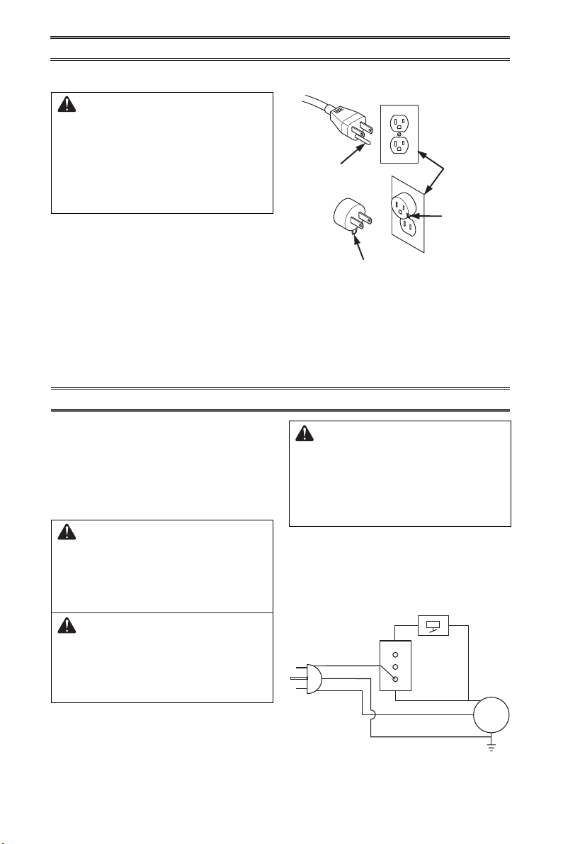
GROUNDING INSTRUCTIONS
This heater is for use on 120 volts. The cord
has a plug as shown at A in Figure 23. An
adapter as shown at C is available for connecting three-blade grounding-type plugs to
two-slot receptacles. The green grounding
lug extending from the adapter must be
connected to a permanent ground such as
a properly grounded outlet box. The adapter
should not be used if a three-slot grounded
receptacle is available.
ELECTRICAL WIRING
Cover of
Grounding Pin
B
Grounded
Outlet Box
C
Adapter
Figure 23 - Grounded Electrical Outlet
Any electrical re-wiring of this appliance must
be done by a qualied electrician. This wiring
must be done in accordance with local codes
and/or in Canada with the current CSA C22.1
Canadian Electrical Code, and for US installations, the National Electrical Code ANSI/
NFPA NO 70.
WARNING: If repairing or
replacing any electrical component or wiring, the original wire
routing, color coding and secur-
ing locations must be followed.
CAUTION: Label all wires
prior to disconnection when
servicing controls. Wiring errors
can cause improper and dangerous operation.
www.usaprocom.com
WARNING: Never attempt to
service heater while it is plugged
in, operating, or hot. Burns and
electrical shock could result.
Only a qualied service person
should service or repair heater.
Verify proper operation after servicing. If any
of the original wire as supplied with the appliance must be replaced, it must be replaced
with a wire of at least a 105º C temperature
rating.
Switch
Black
Green
White
AUTO
O
MAN
Motor
200213-01B22
Page 23
1/2 Glass
Height
Yellow
1/2 Glass
INSPECTING HEATER
IMPORTANT: Owner’s should check pilot ame pattern and burner ame pattern often.
Incorrect ame patterns indicate the need for cleaning (see Care and Maintenance,
page 24) or service.
WARNING: Only a qualied service person should service and
repair heater. This includes maintenance requiring replacement or
alteration of components.
PILOT FLAME PATTERN
Figure 24 shows a correct pilot ame pattern.
Figure 25 shows an incorrect pilot ame pattern. The incorrect pilot ame is not touching
the thermocouple. This will cause the thermocouple to cool, which shuts the heater off.
If pilot ame pattern is incorrect, as shown
in Figure 25
• turn heater off (see To Turn Off Gas to Ap-
pliance, page 20 or 21)
• see Troubleshooting pages 25 through 28.
Notice: Do not mistake orange ames with
yellow tipping. Dirt or other ne particles enter
the heater and burn causing brief patches of
orange ame.
Natural Gas
Shown
3-3.5" WC
NG
8-11" WC
LP
WARNING: If yellow tipping
Figure 24 - Correct Pilot Flame Pattern
occurs, your heater could pro-
duce increased levels of carbon
monoxide. If the burner ame
pattern shows yellow tipping,
follow instructions below.
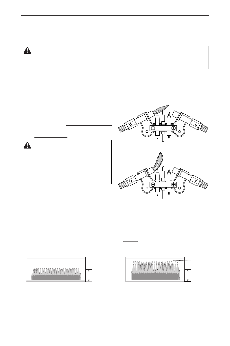
BURNER FLAME PATTERN
Figure 26 shows a correct burner ame pattern. Figure 27 shows an incorrect burner
ame pattern. The incorrect burner ame
pattern shows yellow tipping of the ame. It
also shows the ame higher than 1/2 the heat
shield height.
Height
Figure 26 - Correct Burner Flame Pattern Figure 27 - Incorrect Burner Flame Pattern
Natural Gas
Shown
3-3.5" WC
NG
8-11" WC
LP
Figure 25 - Incorrect Pilot Flame Pattern
If burner ame pattern is incorrect, as shown
in Figure 27
• turn heater off (see To Turn Off Gas to Ap-
pliance, page 20 or 21)
• see Troubleshooting pages 25 through 28.
Tipping
1/2 Glass
Height
www.usaprocom.com
23200213-01B
Page 24

CARE AND MAINTENANCE
WARNING: Turn off heater and let cool before servicing.
CAUTION: You must keep control areas, burner, and circulating
air passageways of heater clean. Inspect these areas of heater before
each use. Have heater inspected yearly by a qualied service techni-
cian. Heater may need more frequent cleaning due to excessive lint
from carpeting, bedding material, pet hair, etc.
WARNING: Failure to keep the primary air opening(s) of the
burner(s) clean may result in sooting and property damage.
ODS/PILOT AND BURNER
Use a vacuum cleaner, pressurized air, or a small, soft bristled brush to clean.
BURNER PILOT AIR INLET
The primary air inlet hole allows the proper
amount of air to mix with the gas. This provides a clean burning ame. Keep this hole
clear of dust, dirt and lint. Clean this air inlet
hole prior to each heating season. A blocked
air hole will create soot. We recommend that
you clean the unit every three months during
operation and have heater inspected yearly
by a qualied service person.
We also recommend that you keep the burner
tube and pilot assembly clean and free of dust
and dirt. To clean these parts we recommend
using compressed air no greater than 30 PSl.
Your local computer store, hardware store,
or home center may carry compressed air in
a can. You can use a vacuum cleaner in the
blow position. If using compressed air in a
can, please follow the directions on the can.
If you don’t follow directions on the can, you
could damage the pilot assembly.
1. Shut off the unit, including the pilot. Allow
the unit to cool for at least thirty minutes.
2. Inspect burner and pilot for dust and dirt.
3. Blow air across the ports/slots and holes
in the burner.
4. Never insert objects into the pilot tube.
Clean the pilot assembly also. A yellow tip on
the pilot ame indicates dust and dirt in the
pilot assembly. There is a small pilot air inlet
about 2" from where the pilot ame comes out
of the pilot assembly (see Figure 28). With
the unit off, lightly blow air through the air
inlet. You may blow through a drinking straw
if compressed air is not available.
Natural Gas
Burner
Pilot Air
Inlet Hole
Figure 28 - Pilot Inlet Air Hole
Ignitor
Electrode
Thermocouple
Propane/LP
Gas Burner
Pilot Air Inlet Hole
Use pressurized air to clean.
Air Passageways
CABINET
Use a soft cloth dampened with a mild soap
and water mixture. Wipe the cabinet to remove dust.
www.usaprocom.com
Exterior
200213-01B24
Page 25

TROUBLESHOOTING
WARNING: If you smell gas:
• Shut off gas supply.
• Do not try to light any appliance.
• Do not touch any electrical switch; do not use any phone in your
building.
• Immediately call your gas supplier from a neighbor’s phone. Follow the gas supplier’s instructions.
• If you cannot reach your gas supplier, call the re department.
WARNING: Only a qualied service technician should service and
repair heater. Make sure that power is turned off before proceeding.
Turn off and let cool before servicing.
CAUTION: Never use a wire, needle, or similar object to clean
ODS/pilot. This can damage ODS/ pilot unit.
IMPORTANT: Operating heater where impurities in air exist may create odors. Cleaning supplies, paint, paint remover, cigarette smoke, cements and glues, new carpet or textiles, etc.,
create fumes. These fumes may mix with combustion air and create odors.
Note: All troubleshooting items are listed in order of operation.
Problem Possible Cause Corrective Action
Using natural gas and
pilot will not light.
Inlet pressure exceeds
9.5" WC.
Bypass pressure switch. See
instructions below.
When using natural gas (NG), there is a
Pressure Switch
pressure switch that acts to turn off the gas
ow to the pilot if the inlet pressure exceeds
9.5" WC. This is to prevent the operation of
the unit on the wrong gas (propane/LP). If
your natural gas supply exceeds 9.5" WC the
unit will not operate. Either contact your gas
supplier to check and adjust the inlet pressure
or a qualied service technician can bypass
the pressure switch.
Before attempting to bypass the pressure
switch, make sure the type of gas being used
is correct. Check to make sure the connection
tting is in the correct inlet on the regulator.
Refer to Connecting to Gas Supply, page 16.
Only a qualied installer should bypass the
pressure switch. To bypass the pressure
switch locate the set screw on the regulator.
Use a small at bladed screw driver to turn the
set screw counterclockwise 2 turns. This will
bypass the pressure switch function.
www.usaprocom.com
The entire gas delivery piping including connections inside the heater should be leak
tested by the qualied installer. After leak
testing the qualied installer should light the
appliance. Refer to the correct ame pattern
as illustrated on page 23. All ame patterns
should be safely inside the product. If for any
reason they are not, stop use of the appliance
and call for repairs.
NG
Pressure Switch Set Screw
Figure 29 - Gas Regulator Pressure
Switch
25200213-01B
Page 26

TROUBLESHOOTING
Problem Possible Cause Corrective Action
When ignitor button is
pressed in, there is no
spark at ODS/pilot.
When ignitor button is
pressed in there is a
spark at ODS/pilot but
no ignition.
ODS/pilot lights but ame
goes out when control
knob is released.
1. Ignitor electrode is positioned wrong. Ignitor electrode is broken.
2. Ignitor electrode is not connected to ignitor cable.
3. Ignitor cable is pinched or
wet.
4 Broken ignitor cable.
5. Bad piezo ignitor.
1. Gas supply is turned off or
equipment shutoff valve is
closed.
2. Control knob not fully
pressed in while pressing
ignitor button.
3. Air in gas lines when installed.
4. ODS / pilot is clogged.
5. Incorrect inlet gas pressure
or inlet regulator is damaged.
6. Control knob not in PILOT
position.
7. Depleted gas supply (propane).
1. Control knob is not fully
pressed in.
2. Control knob is not pressed
in long enough.
3. Equipment shutoff valve is
not fully open.
4. Thermocouple connection is
loose at control valve.
5. Pilot flame not touching
thermocouple, which allows
thermocouple to cool, causing pilot ame to go out. This
problem could be caused by
one or both of the following:
A) Low gas pressure
B) Dirty or partially clogged
ODS/pilot
6. Thermocouple damaged.
7. Control valve damaged.
1. Replace pilot assembly.
2. Replace ignitor cable.
3. Free ignitor cable if pinched
by any metal or tubing. Keep
ignitor cable dry.
4. Replace ignitor cable.
5. Replace piezo ignitor.
1. Turn on gas supply or open
equipment shutoff valve.
2. Fully press in control knob
while pressing ignitor button.
3. Continue holding down control knob. Repeat igniting operation until air is removed.
4.
Clean ODS/pilot (see Care
and Maintenance, page 24) or
replace ODS/pilot assembly.
5. Check inlet gas pressure or
replace inlet gas regulator.
6. Turn control knob to PILOT
position.
7. Contact local propane/LP
gas company.
1. Press in control knob fully.
2. After ODS/pilot lights, keep
control knob pressed in 30
seconds.
3. Fully open equipment shutoff
valve.
4. Hand tighten until snug, and
then tighten 1/4 turn more.
5. A) Contact local natural or
propane/LP gas company
B) Clean ODS/pilot (see
Care and Maintenance,
page 24) or replace ODS/
pilot assembly
6. Replace thermocouple
7. Replace control valve.
www.usaprocom.com
200213-01B26
Page 27

TROUBLESHOOTING
Problem Possible Cause Corrective Action
Burner(s) does not light
after ODS/pilot is lit.
Delayed ignition of
burner(s).
Burner backring during
combustion.
High yellow ame during
burner combustion.
Gas odor during combustion.
Slight smoke or odor
during initial operation.
Heater produces a whistling noise when burner
is lit.
1. Burner orice is clogged.
2. Burner orice diameter is too
small.
3. Inlet gas pressure is too low.
1. Manifold pressure is too low.
2. Burner orice is clogged.
1. Burner orice is clogged or
damaged.
2. Burner is damaged.
3. Gas regulator is damaged.
1. Not enough air.
2. Gas regulator is defective.
3. Inlet gas pressure is too low.
1. Foreign matter between
control valve and burner.
2. Gas leak. (See Warning
Statement at top of page 25).
1. Residues from manufacturing process.
1. Turning control knob to high
(5) position when burner is
cold.
2. Air in gas line.
3. Air passageways on heater
are blocked.
4. Dirty or partially clogged
burner orice.
1. Clean burner orifice (see
Care and Maintenance,
page 24) or replace burner
orice.
2. Replace burner orice.
3. Contact local gas supplier.
1. Contact local gas supplier.
2. Clean burner (see Care and
Maintenance, page 24) or
replace burner orice.
1. Clean burner orifice (see
Care and Maintenance,
page 24) or replace burner
orice.
2. Replace burner.
3. Replace gas regulator.
1. Check burner for dirt and
debris. If found, clean burner
(see Care and Maintenance,
page 24).
2. Replace gas regulator.
3. Contact local gas supplier.
1. Take apart gas tubing and
remove foreign matter.
2. Locate and correct all leaks
(see Checking Gas Connec-
tions, page 17).
1. Problem will stop after a few
hours of operation.
1. Turn control knob to low (1)
position and let warm up for
a minute.
2. Operate burner until air is
removed from line. Have gas
line checked by local gas
supplier.
3 Observe minimum installa-
tion clearances (Figure 4,
page 10).
4 Clean burner (see Care and
Maintenance, page 24) or
replace burner orice.
www.usaprocom.com
27200213-01B
Page 28

TROUBLESHOOTING
Problem Possible Cause Corrective Action
Heater produces a clicking/ticking noise just after
burner is lit or shut off.
White powder residue
forming within burner
box or on adjacent walls
or furniture.
Heater produces unwanted odors.
Heater shuts off in use
(ODS operates).
Gas odor exists even
when control knob is in
OFF position.
Moisture/condensation
noticed on windows.
1. Metal is expanding while
heating or contracting while
cooling.
1. When heated, the vapors
from furniture polish, wax,
carpet cleaners, etc., turn
into white powder residue.
1. Heater is burning vapors from
paint, hair spray, glues, etc.
See IMPORTANT statement,
page 25.
2. Gas leak. See Warning State-
ment at the top of page 25.
3. Low fuel supply (propane/LP
gas only).
1. Not enough fresh air is available.
2. Low line pressure.
3. ODS/pilot is partially
clogged.
1. Gas leak. See Warning
Statement at top of page 25.
2. Control valve is defective.
1. Not enough combustion/
ventilation air.
1. This is common with most
heaters. If noise is excessive, contact qualied service technician.
1. Turn heater off when using
furniture polish, wax, carpet
cleaner or similar products.
1. Ventilate room. Stop using
odor causing products while
heater is running.
2. Locate and correct all leaks
(see Checking Gas Connec-
tions, page 17).
3. Rell supply tank (Propane/
LP models).
1. Open window and/or door for
ventilation.
2. Contact local gas supplier.
3. Clean ODS/pilot (see Care
and Maintenance, page 24).
1. Locate and correct all leaks
(see Checking Gas Connec-
tions, page 17).
2. Replace control valve.
1. Refer to Air for Combus-
tion and Ventilation requirements, page 7.
SERVICE HINTS
• pilot will not stay lit
• burners will have delayed ignition
• replace will not produce specied heat
• propane/LP gas supply might be low (propane/LP units only)
You may feel your gas pressure is too low. If so, contact your local gas supplier.
When Gas Pressure Is Too Low
TECHNICAL SERVICE
You may have further questions about installation, operation, or troubleshooting. If so, contact
ProCom Heating, Inc. at 1-866-573-0674.
When calling, please have your model and serial numbers of your heater ready.
www.usaprocom.com
200213-01B28
Page 29

REPLACEMENT PARTS
Note: Use only original replacement parts. This will protect your warranty coverage for parts
replaced under warranty.
PARTS UNDER WARRANTY
Contact authorized dealers of this product.
If they can’t supply original replacement
parts, call Customer Service toll free at
1-866-573-0674 for referral information.
When calling Customer Service or your dealer,
have ready:
• Your name
• Your address
• Model and serial number of your heater
• How heater was malfunctioning
• Type of gas used (Propane/LP or Natural
gas/NG)
• Purchase date
Usually, we will ask you to return the defective
part to the factory
PARTS NOT UNDER WARRANTY
Contact authorized dealers of this product.
If they can’t supply original replacement
part(s) call Customer Service toll free at
1-866-573-0674 for referral information.
When calling Customer Service have ready:
• Model number of your heater
• The replacement part number
ACCESSORIES
Purchase these heater accessories from your local dealer. If they can not supply these accessories, contact ProCom Heating, Inc. at 1-866-573-0674 for information.
EQUIPMENT SHUTOFF VALVE
For all models. Equipment shutoff valve with
1/8” NPT tap.
OPTIONAL FAN KIT
Optional fan kit, part PF06-YJLF-B (ts
model # MNSD200TBA, MNSD300TBA,
MNSD200HBA, MNSD300HBA,
MNSD200TBA-BB, MNSD300TBA-BB,
MNSD200HBA-BB, MNSD300HBA-BB).
The fan has 3 settings ON/OFF/Auto.
Please refer to PF06-YJLF-B instructions.
FLOOR MOUNTING STAND
For locating heater on the oor, away from a
wall. Complete installation instructions provided with oor mounting stand.
www.usaprocom.com
29200213-01B
Page 30

PARTS
9
1
2
3
4
5
11
14
13
8
6
7
10
15
12
T-Stat
Manual
MODELS MNSD100HBA & MNSD100TBA
www.usaprocom.com
200213-01B30
Page 31

PARTS
MODELS MNSD100HBA & MNSD100TBA
This list contains replaceable parts for your heater. When ordering replacement parts, follow
the instructions listed under Replacement Parts on page 29 of this manual.
ITEM MNSD100HBA MNSD100TBA DESCRIPTION QTY
1 ** ** Cabinet Assembly 1
2 ** ** Reector Unit 1
3 ML087-03 ML087-03 Upper Glass Retainer 1
4 ML086-03 ML086-03 Glass 1
5 ML088-03 ML088-03 Lower Glass Retainer 1
6 ** ** Middle Panel 1
7 MB09003 MB09003 Lower Front Panel Assembly 1
8 MB29003 MB29003 Grill Guard 1
9 161132-01 161132-01 Mounting Bracket 1
10 161133-01 161133-01 Ignitor Assembly 1
11 ** ** Burner Assembly 1
12 ** 161130-01 Thermostat Valve Assembly 1
12 NV2020-1213B ** Manual Control Valve 1
13 ** ** Pressure Regulator Assembly 1
ND0310A-600-P-PI6 ND0310A-600-P-PI6 ODS Pilot 1
14
ML031-03 ** Control Knob 1
15
PARTS AVAILABLE - NOT SHOWN
161607-01 161607-01 Hardware Package 1
** 161605-01 Thermostat Sensing Bulb Clip 1
**Not a eld replaceable part.
www.usaprocom.com
31200213-01B
Page 32

PARTS
MODELS MNSD200TBA & MNSD300TBA
9
2
2
1
11
3
4
5
6
14
7
8
www.usaprocom.com
12
13
10
200213-01B32
Page 33

PARTS
MODELS MNSD200TBA & MNSD300TBA
This list contains replaceable parts for your heater. When ordering replacement parts, follow
the instructions listed under Replacement Parts on page 29 of this manual.
ITEM MNSD200TBA MNSD300TBA
1 ** ** Cabinet Assembly 1
2 ** ** Reector Unit 1
3 ML087-02 ML087-01 Upper Glass Retainer 1
4 ML086-02 ML086-01 Glass 1
5 ML088-02 ML088-01 Lower Glass Retainer 1
6 ** ** Middle Panel 1
7 MB09002 MB09051 Lower Front Panel Assembly 1
8 MB29002 MB29001 Grill Guard 1
9 161562-01 161562-01 Mounting Bracket 1
10 ** ** Pressure Regulator Assembly 1
11 161133-01 161133-01 Ignitor Assembly 1
12 161130-01 161130-01 Thermostat Valve Assembly 1
13 ** ** Burner Assembly 1
14 ND0310A-800-P-PI6 ND0310A-800-P-PI6 ODS Pilot 1
PARTS AVAILABLE - NOT SHOWN
161607-01 161607-01 Hardware Package 1
161605-01 161605-01 Thermostat Sensing Bulb Clip 1
**Not a eld replaceable part.
DESCRIPTION QTY
www.usaprocom.com
33200213-01B
Page 34

PARTS
MODELS MNSD200TBA-BB & MNSD300TBA-BB
9
2
2
1
11
3
4
5
6
14
7
8
www.usaprocom.com
12
13
10
15
16
200213-01B34
Page 35

PARTS
MODELS MNSD200TBA-BB & MNSD300TBA-BB
This list contains replaceable parts for your heater. When ordering replacement parts, follow
the instructions listed under Replacement Parts on page 29 of this manual.
ITEM
**Not a eld replaceable part.
MNSD200TBA-BB MNSD300TBA-BB
1 ** ** Cabinet Assembly 1
2 ** ** Reector Unit 1
3 ML087-02 ML087-01 Upper Glass Retainer 1
4 ML086-02 ML086-01 Glass 1
5 ML088-02 ML088-01 Lower Glass Retainer 1
6 ** ** Middle Panel 1
7 MB09002 MB09051 Lower Front Panel Assembly 1
8 MB29002 MB29001 Grill Guard 1
9 161562-01 161562-01 Mounting Bracket 1
10 ** ** Pressure Regulator Assembly 1
11 161133-01 161133-01 Ignitor Assembly 1
12 161130-01 161130-01 Thermostat Valve Assembly 1
13 ** ** Burner Assembly 1
14 ND0310A-800-P-PI6 ND0310A-800-P-PI6 ODS Pilot 1
15 PF06-YJLF-BMB PF06-YJLF-BMB Fan Accessory 1
16 PF09B PF09B Base Assembly 1
PARTS AVAILABLE - NOT SHOWN
161607-01 161607-01 Hardware Package 1
161605-01 161605-01 Thermostat Sensing Bulb Clip 1
DESCRIPTION QTY
www.usaprocom.com
35200213-01B
Page 36

WARRANTY
KEEP THIS WARRANTY
Model _______________________________
Serial No. ____________________________
Date Purchased _______________________
Keep receipt for warranty verication.
REGISTER YOUR PRODUCT AT WWW.USAPROCOM.COM
IMPORTANT: We urge you to register your product within 10 days of date of installation, complete
with entire serial number which can be found on the rating plate. Please ll out the warranty information above for your personal records. Retain this manual for future reference.
Always specify model and serial numbers when communicating with customer service.
We reserve the right to amend these specications at any time without notice. The only warranty applicable
is our standard written warranty. We make no other warranty, expressed or implied.
LIMITED WARRANTY
ProCom Heating, Inc. warrants this product to be free from defects in materials and components for ONE
(1) year from the date of rst purchase, provided that the product has been properly installed by a qualied
installer in accordance with all local codes and instructions furnished with the unit, operated and maintained in accordance with all applicable instructions. To make a claim under this warranty, the Bill of Sale
or cancelled check must be presented.
RESPONSIBILITY OF OWNER
This warranty is extended only to the original retail purchaser. This warranty covers the cost of part(s)
required to restore this heater to proper operating condition. Warranty part(s) MUST be obtained through
ProCom Heating, Inc. who will provide original factory replacement parts. Failure to use original factory
replacement parts voids this warranty.
IMPORTANT: The heater MUST be installed by a qualied installer in accordance with all local codes
and instructions furnished with the unit or the warranty is voided.
WHAT IS NOT COVERED
This warranty does not apply to parts that are not in original condition because of normal wear and tear or
parts that fail or become damaged as a result of misuse, accidents, lack of proper maintenance or defects
caused by improper installation. Travel, diagnostic cost, labor, transportation and any and all such other
costs related to repairing a defective heater will be the responsibility of the owner.
TO THE FULL EXTENT ALLOWED BY THE LAW OF THE JURISDICTION THAT GOVERNS THE SALE
OF THE PRODUCT, THIS EXPRESS WARRANTY EXCLUDES ANY AND ALL OTHER EXPRESSED
WARRANTIES AND LIMITS THE DURATION OF ANY AND ALL IMPLIED WARRANTIES. INCLUDING
WARRANTIES OF MERCHANTABILITY AND FITNESS FOR A PARTICULAR PURPOSE TO ONE (1)
YEAR ON ALL COMPONENTS FROM THE DATE OF FIRST PURCHASE. PROCOM HEATING, INC.'S
LIABILITY IS HEREBY LIMITED TO THE PURCHASE PRICE OF THE PRODUCT AND PROCOM HEATING, INC. SHALL NOT BE LIABLE FOR ANY OTHER DAMAGES WHATSOEVER INCLUDING INDIRECT.
INCIDENTAL OR CONSEQUENTIAL DAMAGES.
Some states do not allow a limitation on how long an implied warranty lasts or an exclusion or limitation of
accidental or consequential damages, the above limitation on implied warranties, or exclusion or limitation
on damages may not apply to you.
This warranty gives you specic legal right, and you may also have other rights that vary from state to state.
ProCom Heating, Inc.
Bowling Green, KY 42101
www.usaprocom.com
1-866-573-0674
200213-01
Rev.B
07/16
Page 37

CALENTADOR DE GAS DE
US
PARED SIN VENTILAS
MANUAL DE
FUNCIONAMIENTO
E INSTALACIÓN DEL
PROPIETARIO
LLAMA AZUL MODELOS
MNSD100TBA, MNSD200TBA
MNSD300TBA, MNSD100HBA
MNSD200TBA-BB
MNSD300TBA-BB
ADVERTENCIA: Este
aparato está equipado para
funcionar con gas (natural
y propano). No se permite
®
convertir más que a gas
natural o gas propano.
ADVERTENCIA: si la información contenida en este
manual no se sigue al pie de la letra, se puede producir un
incendio o una explosión que podría ocasionar daños a
la propiedad, lesiones personales o la pérdida de la vida.
- No guarde ni utilice gasolina u otros vapores y líquidos
inamables cerca de este aparato ni de cualquier otro.
- QUÉ HACER SI PERCIBE OLOR A GAS
• No intente encender ningún aparato.
• No toque ningún interruptor eléctrico; no use ningún
teléfono en el edicio.
• Llame inmediatamente a su proveedor de gas desde
el teléfono de algún vecino. Siga las instrucciones
del proveedor de gas.
• Si no puede localizar al proveedor de gas, llame al
departamento de bomberos.
- La instalación y el servicio deben ser realizados por
un instalador capacitado, una agencia de servicio o el
proveedor de gas.
¿Preguntas, problemas, piezas faltantes? Antes de volver a la tienda, llame a
nuestro Departamento de Servicio al Cliente al 1-866-573-0674, de lunes a viernes de
7:30 a.m. a 4:15 p.m., Hora del Centro, o envíe un correo electrónico a
customerservice@usaprocom.com.
Page 38

TABLA DE CONTENIDOS
Seguridad ................................................ 39
Especicaciones ...................................... 41
Agencia de Instalación Calicada............ 42
Características del Producto ................... 42
Normas Locales....................................... 43
Identicación del Producto ...................... 43
Desempaque ........................................... 44
Vapor De Agua: Un Producto Derivado
de Los Calentadores de Habitación
Sin Ventilación ................................... 44
Aire para combustión y ventilación .......... 44
Instalación ............................................... 46
Funcionamiento ....................................... 57
Conexión Eléctrica................................... 60
Cableado Eléctrico .................................. 61
Inspección del calentador ........................ 62
Cuidado y mantenimiento ........................ 63
Solución de problemas ........................... 64
Consejos para servicio ............................ 68
Servicio técnico ....................................... 68
Piezas de repuesto .................................. 69
Accesorios ............................................... 69
Piezas ...................................................... 70
Garantía................................................... 76
GUARDE ESTE MANUAL
INSTALADOR: Deje este manual con el aparato.
CONSUMIDOR: Conserve este manual para
referencias futuras.
Este es un calentador de llama de gas sin ventilación.
Utiliza aire (oxígeno) de la habitación en la que se instala.
Se deben tomar las medidas necesarias para asegurar
que haya suciente aire para ventilación y combustión.
Consulte la sección Aire para combustión y ventilación,
en la página 44 de este manual.
ADVERTENCIA:La instalación, ajuste, alteración,
servicio o mantenimiento inadecuados pueden provocar lesiones o daños a la propiedad. Consulte este manual para conocer los procedimientos de instalación y
operación correctos. Para obtener asistencia o información adicionales consulte a un instalador capacitado,
agencia de servicio o al proveedor de gas.
Este aparato puede ser instalado en una casa móvil
con ubicación permanente y adquirida en el mercado
de posventa*, siempre que no esté prohibido por los
códigos locales.
Este dispositivo es sólo para su uso con propano o
gas natural. No se permite la conversión de campo por
cualquier otro medio, incluido el uso de un kit.
* Mercado de posventa: venta completada por parte del fabricante, sin nes de reventa
www.usaprocom.com
200213-01B38
Page 39

SEGURIDAD
IMPORTANTE: Lea este manual del
propietario cuidadosa y completa-
mente antes de intentar ensamblar,
operar o dar servicio a este calentador. El uso inadecuado de este
calentador puede causar daños a
la propiedad, lesiones graves o la
muerte por quemaduras, incendio,
explosión, electrocución e intoxi-
cación con monóxido de carbono.
No seguir estas instrucciones
anula la garantía.
La instalación y reparación de
este producto deben estar a cargo
sólo de personal calicado para la
instalación, una empresa de servicio o el proveedor de gas local.
ADVERTENCIA: Mantenga el
área limpia y libre de materiales
combustibles, gasolina y otros
vapores y líquidos inamables.
ADVERTENCIA: Este dispositivo se puede utilizar con gas
propano o gas natural. Se envía
desde la fábrica ajustado para
su uso con gas propano.
Este aparato está diseñado para
usarse únicamente con el tipo
de gas indicado en la placa de
clasicación. Este aparato no se
puede convertir para que utilice
otro tipo de gas.
PELIGRO: ¡La intoxicación
con monóxido de carbono puede
resultar en la muerte!
Intoxicación con monóxido de carbono:
los síntomas iniciales de la intoxicación con
monóxido de carbono son semejantes a los
de la gripe, con dolores de cabeza, mareos
y/o náusea. Si usted presenta estos síntomas,
es posible que el calentador no esté funcio-
www.usaprocom.com
nando correctamente. ¡Respire aire fresco
inmediatamente! Haga que le den servicio
al calentador. El monóxido de carbono afecta
más algunas personas que a otras. Las más
afectadas son mujeres embarazadas, personas con enfermedades del corazón, de los
pulmones o anemia, aquellas bajo la inuencia del alcohol y aquellas a grandes altitudes.
Gas natural y gas propano/LP: el gas natural y gas propano/LP son gases inodoros.
Al gas propano se le agrega un agente con
olor. El olor le ayuda a detectar las fugas de
gas. Sin embargo, el olor que se añade al gas
puede desvanecerse. Es posible que haya
gas presente aunque no haya ningún olor.
ADVERTENCIA: Cualquier
cambio a este calentador o a sus
controles puede ser peligroso.
ADVERTENCIA: No utilice
ningún tipo de accesorio de
soplador, accesorio para inter-
cambio de calor ni ningún otro
accesorio que no esté aprobado
para su uso con este calentador.
ADVERTENCIA: Supervise
cuidadosamente a los niños
pequeños cuando estén en la
habitación en la que se encuentra el calentador.
ADVERTENCIA: Asegúrese
que la rejilla de resguardo esté
puesta antes de hacer funcionar
el calentador.
ADVERTENCIA: Debido a las
altas temperaturas generadas
por este aparato, éste se debe
colocar fuera de las rutas de paso
y alejado de muebles y cortinas.
39200213-01B
Page 40

SEGURIDAD
ADVERTENCIA: Este calentador alcanza temperaturas muy
altas cuando el calentador está
en funcionamiento. Mantenga a
niños y adultos alejados de las
supercies calientes para evitar
quemaduras o que la ropa se
encienda. El calentador permanecerá caliente durante algún
tiempo después de que se ha
apagado. Permita que la super-
cie se enfríe antes de tocarla.
ADVERTENCIA: No coloque
ropa ni otros materiales inamables sobre el aparato ni cerca del
mismo. Nunca coloque ningún
objeto sobre el calentador.
1. No ponga los tanques de suministro de
propano o gas LP dentro de ninguna estructura. Sitúe los tanques de suministro
de propano o gas LP en el exterior.
2. Calentadores de una potencia máxima
de más de 6,000 BTU/h que no deben
instalarse en un cuarto de baño. Calentadores de una potencia máxima de más
de 10,000 BTU/h que no deben instalarse
en un dormitorio.
3. Este calentador necesita ventilación con
aire fresco del exterior para funcionar
correctamente. Este calentador tiene un
sistema de apagado de seguridad con
detección de agotamiento de oxígeno
(ODS). El ODS apaga el calentador cuando no hay suciente aire fresco. Consulte
Aire para combustión y ventilación, en la
páginas 44 a 45. Si el calentador continúa apagándose, consulte Solución de
problemas, páginas 64 a 68.
4. Mantenga todas las entradas de aire del
frente y fondo del calentador limpias y
libres de escombros. Esto asegurará aire
suciente para la combustión..
5. Si el calentador se apaga, no lo vuelva
a encender hasta que se le haya proporcionado aire fresco del exterior. Si el
calentador continua apagando se debera
ser revisado por personal calicado.
6. No haga funcionar el calentador:
• Donde se utilicen o almacenen líquidos
o vapores inamables.
• En condiciones con mucho polvo.
7. Apague el calentador antes de usar pulidores de muebles, ceras, limpiadores de
alfombras o productos parecidos. Si se
calientan, los vapores que se desprenden de estos productos pueden producir
un residuo de polvo blanco dentro de la
caja del calentador, o en las paredes y los
muebles adyacentes.
8. Sólo Modelos Controlados Manual: El
siempre ejecución calefactor con mando
de control al piloto/IGN, baja (5) o alta
(1) bloqueado posiciones. Nunca establezca perilla de control entre posiciones
bloqueadas. Pueden resultar mala combustión y mayores niveles de monóxido
de carbono.
9. No use este calentador si alguna de sus
partes estuvo sumergida en agua. Llame
inmediatamente a un técnico de servicio
para que inspeccione el calentador y para
que remplace las piezas del sistema de
control o los controles de gas que hayan
estado sumergidos en agua.
10. Apague y desconecte el calentador, déjelo
enfriar antes de cualquier reparación.
Sólo un técnico calicado debe realizar
el mantenimiento o reparar el calentador.
11. Hacer funcionar el calentador a alturas
superiores a 1,371 m (4,500 pies) puede
ocasionar que el piloto se apague.
12. Para evitar problemas de rendimiento en
los modelos de gas propano/LP, no use
tanques de gas propano/LP de menos de
45 kg (100 libras) de capacidad.
PROCOM HEATING, INC. INFORMACIÓN DE PATENTES
Este producto puede estar cubierto por una o más de las siguientes patentes de Estados Unidos:
8,915,239 8,851,065 8,764,436 8,757,202 8,757,13 8,752,541 8,568,136 8,545,216
8,517,718 8,516,878 8,506,290 8,465,277 8,317,511 8,297,968 8,281,781 8,241,034
8,235,708 8,152,515 8,011,920 7,967,006 7,967,007 7,654,820 7,730,765 7,677,236
7,607,426 7,434,447
www.usaprocom.com
200213-01B40
Page 41

ESPECIFICACIONES
MODELO MNSD100TBA MNSD200TBA MNSD300TBA
BTU (disponible) 10,000 20,000 30,000
Encendido Piezoeléctrico Piezoeléctrico Piezoeléctrico
Tipo de gas Con gas natural Con gas natural Con gas natural
Ajuste del regulador de
presión:
Presión del gas de entra-
da* (pulg. de agua)
Tipo de gas Con gas propano Con gas propano Con gas propano
Ajuste del regulador de
presión:
Presión del gas de entra-
da* (pulg. de agua)
Dimensiones del ca-
lentador (alto x ancho x
profundidad)
Dimensiones caja (alto x
ancho x profundidad)
Pesa de calentador
Peso con embalaje
MODELO MNSD100HBA MNSD200TBA-BB MNSD300TBA-BB
BTU (disponible) 10,000 20,000 30,000
Encendido Piezoeléctrico Piezoeléctrico Piezoeléctrico
Tipo de gas Con gas natural Con gas natural Con gas natural
Ajuste del regulador de
presión:
Presión del gas de entra-
da* (pulg. de agua)
Tipo de gas Con gas propano Con gas propano Con gas propano
Ajuste del regulador de
presión:
Presión del gas de entra-
da* (pulg. de agua)
Dimensiones del calentador (alto x ancho x
profundidad)
Dimensiones caja (alto x
ancho x profundidad)
Pesa de calentador
Peso con embalaje
4" de c.a. 4" de c.a. 4" de c.a.
Máximo 9" de c.a. Máximo 9" de c.a. Máximo 9" de c.a.
Mínimo 5" de c.a. Mínimo 5" de c.a. Mínimo 5" de c.a.
9" de c.a. 9" de c.a. 9" de c.a.
Máximo 14" de c.a. Máximo 14" de c.a. Máximo 14" de c.a.
Mínimo 11" de c.a. Mínimo 11" de c.a. Mínimo 11" de c.a.
19 1/8" × 14 1/8" × 6 3/8" 23 1/2" × 19 1/4" × 8" 23 1/2" x 26 5/8" x 8"
22 ×16 3/4" × 8 1/8" 25 3/4" × 21 3/4" × 9 1/4" 25 3/4" x 28 1/2" x 9 1/4"
14.6 lbs 22.2 lbs 28.1 lbs
17.6 lbs 26.2 lbs 33.1 lbs
4" de c.a. 4" de c.a. 4" de c.a.
Máximo 9" de c.a. Máximo 9" de c.a. Máximo 9" de c.a.
Mínimo 5" de c.a. Mínimo 5" de c.a. Mínimo 5" de c.a.
9" de c.a. 9" de c.a. 9" de c.a.
Máximo 14" de c.a. Máximo 14" de c.a. Máximo 14" de c.a.
Mínimo 11" de c.a. Mínimo 11" de c.a. Mínimo 11" de c.a.
19 1/8" × 14 1/8" × 6 3/8"
22 ×16 3/4" × 8 1/8" 25 3/4" × 21 3/4" × 9 1/4" 25 3/4" x 28 1/2" x 9 1/4"
14.1 lbs 25.1 lbs 31 lbs
17.1 lbs 29.1 lbs 36 lbs
23 1/2" × 19 1/4" × 8" 23 1/2" x 26 5/8" x 8"
Requisito eléctrico para el kit del ventilador (si está equipado)
Voltaje • 120 VAC (V.C.A.), 60 Hz
www.usaprocom.com
41200213-01B
Page 42

AGENCIA DE INSTALACIÓN CALIFICADA
La instalación y el remplazo de tuberías de
gas, de equipos o de accesorios para la
utilización de gas y la reparación y el mantenimiento de los equipos deben estar a cargo
sólo de una agencia calicada. El término
“agencia calicada” signica cualquier persona, empresa, corporación o compañía que, en
persona o por medio de un representante, se
dedique a y sea responsable de:
CARACTERÍSTICAS DEL PRODUCTO
PILOTO DE SEGURIDAD
El calentador posee un piloto que cuenta
con un sistema de apagado de seguridad
por medio de un sensor de agotamiento de
oxígeno (ODS). El sensor de agotamiento de
oxígeno del piloto apaga el calentador si no
hay suciente cantidad de aire fresco.
2 OPCIONES DE GAS
DISPONIBLES
El calentador está diseñado para funcionar
con gas propano o con gas natural. El calenta-
a) Instalar, probar o remplazar tuberías de
gas o
b) Conectar, instalar, probar, reparar o reali-
zar mantenimiento de equipos; que tenga
experiencia en este tipo de trabajos; que
esté al tanto de todas las precauciones
necesarias y que cumpla con todas las
exigencias de las autoridades que tienen
jurisdicción.
dor es enviado de fábrica listo para conectarse a gas propano. Para cambiarlo fácilmente
a gas natural, el instalador calicado debe
seguir las instrucciones de la página 51 y las
indicaciones que aparecen en el calentador
CONTROL TERMOSTÁTICO
(Modelos termostato sólo)
El control apaga y enciende el quemador de
forma automática por ciclos para mantener
una temperatura ambiente deseada.
www.usaprocom.com
200213-01B42
Page 43

NORMAS LOCALES
Instale y use el calentador con cuidado. Siga
todas las normas locales. A falta de normas locales, utilice la última edición del Código Nacional
de Gas Combustible, ANSI Z223.1/NFPA 54*.
*Disponible en:
American National Standards Institute. Inc.
25 West 43rd Street
New York, NY 10036, EE.UU.
National Fire Protection Association, Inc.
Batterymarch Park
Quincy, MA 02269, EE.UU.
IDENTIFICACIÓN DEL PRODUCTO
Estado de Massachusetts: La instalación
la debe realizar un plomero o un instalador
de gas con licencia para ejercer en el estado de Massachusetts.
Los vendedores de calentadores complementarios de interiores a base de gas
propano o de gas natural y sin ventilación
deben proporcionar a cada cliente una
copia del 527 CMR 30 al realizar la venta.
En el estado de Massachusetts la manija
del gas debe ser una manija tipo T. El estado de Massachusetts requiere que el conector exible no exceda de 3 pies de largo.
Botón de
encendido
Perilla de
control
Rejilla
Panel
anterior
Gabinete del calentador
Figura 1 - Calentador de gas sin
ventilación
www.usaprocom.com
Quemador
43200213-01B
Page 44

DESEMPAQUE
1. Saque el calentador de la caja.
2. Retire todo el empaque de protección que
se agregó al calentador para su envío.
3. Revise el calentador para ver si hay algún
daño debido al transporte. Si el calentador está dañado, informe de inmediato al
distribuidor donde lo compró.
VAPOR DE AGUA: UN PRODUCTO DERIVADO DE LOS CALENTADORES DE HABITACIÓN SIN VENTILACIÓN
El vapor de agua es un producto derivado
de la combustión del gas. Un calentador de
habitación sin ventilación produce aproximadamente 29,57 ml (1 onza) de agua por cada
1,000 BTU (0,29 kW) de entrada de gas por
hora. Los calentadores de habitación sin ventilación son recomendables como calefacción
suplementaria (una habitación) más que como
fuente principal de calefacción (una casa
entera). En la mayoría de las aplicaciones de
calefacción suplementaria, el vapor de agua
no constituye un problema. En la mayoría de
las aplicaciones, el vapor de agua contribuye
a la baja humedad de la atmósfera que se
experimenta en climas fríos.
AIRE PARA COMBUSTIÓN Y VENTILACIÓN
ADVERTENCIA: Este calen-
tador no se debe instalar en un
espacio reducido o excepcionalmente hermético a menos que se
tomen las precauciones necesa-
rias para la combustión adecuada
y ventilación de aire. Lea las
instrucciones siguientes para
asegurarse de aire fresco para
éste y otros aparatos que queman
combustible en su hogar.
Las casas de hoy se construyen más energía
eciente que nunca. Nuevos materiales, mejor
aislamiento y los nuevos métodos de construcción ayudan a reducir la pérdida de calor
en los hogares. Los propietarios de viviendas
burletes y calafateo alrededor de las ventanas
y puertas para mantener el aire frío y el aire
caliente adentro Durante la temporada de
calor, los dueños de casa quieren que sus
casas lo más hermética posible.
Los siguientes pasos asegurarán que el vapor
de agua no se convierta en un problema:
1. Asegúrese de que el calentador tenga
el tamaño adecuado para la aplicación,
incluidas la combustión y la circulación
adecuadas del aire.
2. Si hay humedad elevada, se puede utilizar
un deshumidicador para ayudar a reducir
el contenido de vapor de agua del aire.
3. No utilice un calentador de habitación
sin ventilación como fuente principal de
calefacción.
Mientras que es bueno para hacer su hogar de
energía eciente, su hogar necesita respirar. El
aire fresco debe entrar a su casa. Todos los aparatos que queman combustible necesitan aire fresco
para la combustión y la ventilación adecuada.
Los extractores de aire, chimeneas, secadoras de ropa y aparatos que queman
combustible toman aire de la casa durante su
funcionamiento. Usted debe proporcionar aire
fresco adecuado para estos aparatos. Esto
asegurará una adecuada ventilación de los
aparatos que queman combustible ventilados.
ADVERTENCIA: Este calen-
tador no se debe instalar en una
habitación o espacio a menos
que el volumen requerido de aire
de combustión en interiores es
proporcionada por el método
descrito en el Código Nacio-
nal de Gas Combustible, ANSI
Z223.1/NFPA 54, el Fuel Gas
Code Internacional o aplicable
códigos locales.
www.usaprocom.com
200213-01B44
Page 45

AIRE PARA COMBUSTIÓN Y VENTILACIÓN
Entrada
de aire
adyacente,
ADVERTENCIA: Si la zona en la que la estufa se puede operar no
cumple con el volumen requerido de aire de combustión en interiores , combustión y de ventilación serán facilitados por uno de los
métodos descritos en el Código Nacional de Gas Combustible, ANSI
Z223.1/NFPA 54, el Fuel Gas Code Internacional o con los códigos
locales aplicables.
AIRE PARA VENTILACIÓN
Aire del interior de la construcción
para ventilación
Este aire fresco viene de un espacio adyacente
no connado. Cuando se ventila mediante un
espacio adyacente no connado, debe haber
dos aberturas permanentes en la pared que
está entre los dos espacios: una abertura
30.4 cm (12") del techo y otra 30.4 cm (12") del
piso (consulte las opciones 1 y 2, gura 2). También se puede quitar la puerta de la habitación
adyacente (consulte la opción 3, gura 2). Consulte el Código Nacional de Gas Combustible,
ANSI Z223.1/NFPA 54, Aire para Combustión
y Ventilación para conocer el tamaño requerido
de las rejillas o los conductos de ventilación.
30.5 cm
(12")
Aire del exterior para ventilación
Proporcione aire fresco adicional mediante
el uso de rejillas o conductos de ventilación.
Debe haber dos aberturas permanentes: una
a 30.48 cm (12") del techo y otra a 30.48 cm
(12") del suelo. Conecte estos elementos
directamente al exterior o a los espacios que
estén abiertos al exterior. Estos espacios
incluyen áticos y espacios debajo del piso
de la casa. Consulte el Código Nacional de
Gas Combustible, ANSI Z223.1/NFPA 54, Aire
para combustión y ventilación para conocer
el tamaño requerido de las rejillas o los conductos de ventilación.
IMPORTANTE: No haga aberturas de entrada o de salida de aire hacia el ático si éste
tiene ventilación eléctrica controlada por un
termostato. El aire caliente que entre al ático
activará la ventilación eléctrica.
Rejillas de ventilación hacia
Rejillas de
ventilación
hacia una
habitación
opción 1
O quite
la puerta
hacia la
habitación
adyacente,
opción 3
una habitación adyacente,
30.5 cm
(12")
opción 2
Figura 2 - Aire del interior de la
construcción para ventilación
Nota: Base no incluido. No para su uso en
dormitorios o baños.
www.usaprocom.com
Ático ventilado
Espacio ventilado
Salida
de aire
Salida de aire
Entrada de aire
Figura 3 - Aire del exterior para
ventilación
debajo del piso
Al ático
Al espacio
debajo
del piso
45200213-01B
Page 46

INSTALACIÓN
AVISO: Este calentador está
diseñado para utilizarse como
calefacción adicional. Use este
calentador junto con su sistema
de calefacción principal. No
instale este calentador como
fuente de calefacción principal.
Si tiene un sistema de calefacción central, puede activar el
ventilador de circulación del
sistema mientras utiliza el calentador. Esto ayudará a que el
calor circule por toda la casa.
En caso de una interrupción de
la energía eléctrica, puede usar
este calentador como su fuente
de calefacción principal.
PRECAUCIÓN: Si instala
el calentador en un garaje de
una casa
• el piloto y el quemador del
calentador deben estar por lo
menos a 45.7 cm (18") sobre
el piso
• sitúe el calentador donde nin-
gún vehículo en movimiento lo
pueda golpear
ADVERTENCIA: Un técni-
co calicado debe realizar la
instalación. Respete todos las
normas locales.
ADVERTENCIA: Nunca ins-
tale el calentador
• 10,000 Btu /hr en un baño
• más de 10,000 Btu/Hr en un
dormitorio o baño (Verique
los códigos locales.)
• en un vehículo recreativo
• donde cortinas, muebles, ropa
u otros objetos inamables
estén a menos de 0.914 m (36")
del frente, de la parte superior
o laterales del calentador.
• en áreas de mucho tráco
• en áreas con mucho viento o
con corrientes fuertes de aire
PRECAUCIÓN: Este calentador crea corrientes de aire
caliente. Estas corrientes mue-
ven el calor hacia la supercie
de las paredes próximas al
calentador. La instalación del
calentador cerca de paredes con
recubrimientos de vinilo o tela,
o la operación del calentador
en lugares donde existan impurezas en el aire (como humo
de tabaco, velas aromáticas,
líquidos limpiadores, lámparas
de aceite o de queroseno, entre
otros), puede manchar las paredes o producir olores.
IMPORTANTE: Los calentadores sin ventilación añaden humedad al aire. Aunque esto
es benéco, la instalación del calentador en
habitaciones sin suciente aire de ventilación
puede ocasionar la formación de moho debido
al exceso de humedad. Consulte Aire para
Combustión y Ventilación en la página 44.
VERIFIQUE EL TIPO DE GAS
Asegúrese de que el suministro de gas es
apropiado para el calentador. De lo contrario,
llame al distribuidor donde compró el calentador para el calentador de tipo adecuado.
www.usaprocom.com
200213-01B46
Page 47

TECHO
nima a la superficie de la
PISO
INSTALACIÓN
DISTANCIA DE SEPARACIÓN DE COMBUSTIBLES
Siga con atención las siguientes instrucciones. Este calentador es una unidad de
montaje en la pared diseñada para apoyarse
directamente sobre el suelo o una base de
repisa.
ADVERTENCIA: Mantenga
las distancias mínimas como
se muestra en la Figura 4. Si es
posible, proporcione distancias
mayores respecto al suelo, al techo y a las paredes adyacentes.
Mida desde el punto más alejado
del calentador.
UBICACIÓN DEL CALENTADOR
Este calentador está diseñado para montarse
en la pared. Para mayor comodidad y eciencia, instale el calentador:
COLOCACIÓN DEL CALENTADOR EN LA PARED
Soporte de montaje
El soporte de montaje se encuentra en el panel posterior del calentador (consulte la Figura
5). Se colocó con cinta en ese lugar para el
transporte. Retire el soporte de montaje del
panel posterior.
15.24 cm
(6")
Distancias
mínimas
de los
laterales
del
calentador
Lado
izquierdo
5 cm (2") Distancia mí
alfombra, azulejo u otro material combustible
Un mínimo
de 91.5 cm
(36")
Lado
derecho
Figura 4 - Distancias mínimas de
montaje vistas desde la parte anterior
del calentador
• Donde haya fácil acceso para la operación,
inspección y servicio.
• En el lugar más frío de la habitación.
Desmontaje del panel anterior del
calentador
1. Quite los dos tornillos cerca de esquinas
inferior del panel frontal inferior.
2. Tire hacia abajo del avance de panel
frontal inferior y, a continuación, abajo
(consulta la gura 6).
Soporte de montaje
Figura 5 - Ubicación de abrazadera de
montaje
www.usaprocom.com
Figura 6 - Desmontaje del panel anterior
del calentador
47200213-01B
Page 48

INSTALACIÓN
Métodos para jar el soporte de
montaje a la pared
Use únicamente el último oricio de cada
extremo del soporte de montaje para jarlo a
la pared. Fije el soporte de montaje a la pared
mediante una de las dos maneras siguientes:
Fijación a viga de pared: este método proporciona la sujeción más rme. Inserte los
tornillos de montaje en el soporte de montaje
y en las vigas de pared.
Fijación a anclajes de pared: este método
le permite jar el soporte de montaje en paredes huecas (las áreas de la pared que se
encuentran entre los maderos) o en paredes
sólidas (de concreto o mampostería).
Decida cuál método se ajusta mejor a sus
necesidades. Cualquiera de los dos métodos proporcionará un apoyo seguro para el
soporte de montaje.
Cómo marcar las ubicaciones de
los tornillos
1. Fije el soporte de montaje a la pared con
cinta, en el lugar donde estará situado.
Asegúrese de que el soporte de montaje
esté nivelado.
ADVERTENCIA: mantenga
las distancias mínimas que se
muestran en la gura 4, página
47. Si puede, proporcione distancias mínimas mayores con
respecto al piso y la pared de
unión.
2. Marque la ubicación de los tornillos en la
pared (consulte la gura 7).
Nota:Marqueúnicamenteelúltimooricio
de cada extremo del soporte de montaje.
Inserte los tornillos de montaje en estos
oriciossolamente.
3. Quite la cinta y el soporte de montaje de
la pared.
Instalación del soporte de montaje
a la pared
Nota: Los anclajes de pared, los tornillos de
montaje y los separadores se encuentran en
el paquete de ferretería. El paquete de ferretería se incluye con el calentador.
17 cm (6 3/4")
Min.
Inserte los tornillos
de montaje s
través del último
orificio de cada extremo
Pared adyacente
31 cm (12
Piso
1
/8")
ólo a
36.8 cm
1
/2")
(14
Min.
Modelos: MNSD100TBA Y MNSD100HBA
27 cm (10 5/8")
Min.
Inserte los tornillos
de montaje s
través del último
orificio de cada extremo
Pared adyacente
ólo a
Piso
47 cm
(18
Min.
1
/2")
Modelos:
MNSD200TBA, MNSD300TBA,
MNSD200TBA-BB, MNSD300TBA-BB
Figura 7 - Distancias mínimas del
soporte de montaje
www.usaprocom.com
200213-01B48
Page 49

INSTALACIÓN
Método de jación a viga de pared
Para jar el soporte de montaje a las vigas
de pared:
1. Perfore oricios en los lugares marcados
utilizando una broca de 9/64".
2. Coloque el soporte de montaje en la
pared. Alinee el último oricio de cada
extremo del soporte con los oricios que
perforó en la pared.
3. Inserte los tornillos de montaje en el soporte y en las vigas de pared.
4. Apriete los tornillos hasta que el soporte
de montaje esté asegurado rmemente a
las vigas de pared.
Método de jación a anclajes de pared
Para jar el soporte de montaje en paredes
huecas (el área entre las vigas) o en paredes
sólidas (de concreto o mampostería)
1. Perfore oricios en los lugares marcados
utilizando una broca de 5/16". Para las
paredes sólidas (de concreto o mampostería), perfore a una profundidad de por
lo menos 2.5 cm (1").
2. Doble el anclaje de pared como se muestra en la gura 8.
3. Inserte el anclaje de pared (las alas primero) en el oricio. Golpee suavemente
el anclaje para introducirlo en la pared.
4. Para paredes delgadas, de 1.3 cm (1/2")
o menos, inserte la llave roja en el anclaje
de pared. Empuje la llave roja para que
abra las alas de anclaje (consulte le Fi-
gura 9).
IMPORTANTE: ¡no golpee la llave con un
martillo! Para paredes gruesas, de más de
1.3 cm (1/2") de ancho, o paredes sólidas,
no abra las alas.
5. Coloque el soporte de montaje en la
pared. Alinee el último oricio de cada
extremo del soporte con los anclajes de
pared.
6. Inserte los tornillos de montaje en el soporte y en los anclajes de pared.
7. Apriete los tornillos hasta que el soporte
de montaje esté asegurado rmemente a
la pared.
Colocación del calentador en el
1. Localice las dos ranuras horizontales en
2. Coloque el calentador en el soporte de
Lengüeta
saliente
Figura 10 - Montaje del calentador en el
soporte de montaje
el panel posterior del calentador (consulte
la gura 10).
montaje. Deslice las ranuras horizontales
hacia las lengüetas salientes del soporte
de montaje.
Ranuras horizontales
Soporte de
montaje
(jado a la
pared)
soporte de montaje
Figura 8 - Cómo doblar el anclaje
Figura 9 - Cómo abrir las alas del anclaje
para paredes delgadas
www.usaprocom.com
49200213-01B
Page 50

INSTALACIÓN
Instalación de los tornillos de
montaje inferiores
1. Instale el soporte base en la parte inferior
del calentador con dos tornillos. Puede
ser más cómodo retirar el calentador del
soporte de pared para la colocación.
2. Coloque el calentador sobre el soporte de
montaje de pared.
3. Marque la ubicación de los tornillos en la
pared.
4. Quite el calentador del soporte de montaje.
5. Si va a instalar los tornillos de montaje
inferiores en una pared hueca o sólida,
instale los anclajes de pared. Siga los
pasos 1 a 4 en Métododejaciónaan-
clajes de pared, pagina 49. Si va a instalar
el tornillo inferior de montaje en la viga
de pared, perfore oricios en los lugares
marcados, con una broca de 9/64".
6. Vuelva a colocar el calentador en el soporte de montaje.
7. Coloque los separadores entre los oricios de montaje inferiores y el anclaje de
pared o el oricio que perforó.
8. Sostenga el separador en su sitio con una
mano. Con la otra mano, inserte el tornillo
de montaje a través del oricio inferior de
montaje y del separador. Coloque la punta
del tornillo en la abertura del anclaje de
pared o del oricio que perforó.
9. Apriete los tornillos hasta que el calentador esté asegurado rmemente a la pared.
No los apriete demasiado.
Nota: no vuelva a colocar el panel ante-
rior en este momento. Coloque el panel
anterior después de hacer las conexiones
de gas y de revisar si hay fugas.
Front View
Vista frontal
Pared
Calentador
Separador
Vista lateral
Side View
Figura 11 - Instalación de los tornillos de
montaje inferiores
INSTALACIÓN DE LAS PATAS BASE
(Si está equipado)
Antes de instalar el calentador a la base,
asegúrese de tener los siguientes artículos:
(2) patas base
(4) tornillos para lámina de metal
Procedimiento de instalación:
1. Coloque el respaldo del calentador sobre
una mesa con su parte inferior proyectándose fuera del borde de la mesa.
2. Coloque las patas base en el calentador
con los tornillos para lámina de metal.
www.usaprocom.com
Patas Base
Tornillo para
lámina de metal
Figura 12 - Instalación de las patas base
200213-01B50
Page 51

INSTALACIÓN
SELECCIÓN DE GAS
Este aparato viene ajustado
de fábrica para gas propano/
LP. No se requieren cambios
para la conexión a propano/
L P. Sólo un instalador o técnico
de servicio calificado puede
realizar la selección de gas y la
conexión al suministro de gas.
PRECAUCIÓN: Dos instala-
ciones de líneas de gas, al mismo
tiempo están prohibidos.
PRECAUCIÓN: Para evitar
la fuga de gas para el gas no se
utiliza en la entrada del regulador, un instalador o técnico de
servicio calicado debe utilizar
el enchufe suministrado.
Usted notará un código de colores
émbolo en el interior del regulador. Esto es normal. Cuando se
inserta el accesorio de conexión
de entrada y apretada, este émbolo se echó hacia atrás, mediante
la instalación de hacer todos los
ajustes para el gas que se suministra. NO QUITE EL ÉMBOLO. El
regulador no funcionará.
INLET GAS PRESSURE
MAX 1/2 PSIG (3.5 KPA)
NG
Conexión de gas
Figura 13 - Parte posterior del calentador
Amarilla gas natural
émbolo debajo
enchufe del metal
Inserte gas
montaje de
Gas Natural
Figura 14 - Regulador de Gas
LPG
Azul propano/LP
gas tapa émbolo
debajo de polvo
Insertar gas montaje
para Propano/LP gas
PARA EL PROPANO/LP
INSTALACIÓN DE GAS: AZUL
1. Retire la cubierta de polvo azul.
El regulador de entrada es un có-
digo de color para la identicación
del tipo de gas correcta. El azul
es para el propano (gas LP) y el
amarillo es para el gas natural.
www.usaprocom.com
Cubierta de
polvo azul
NO QUITE
Azul propano/LP gas
émbolo
Instale Gas Fitting Aquí
51200213-01B
Page 52

INSTALACIÓN
2.
Aplique sellador de roscas a las roscas en el
accesorio de conexión. Mientras presiona, gire
hacia la derecha el ajuste hasta que las roscas
se acoplan al regulador. Después de la instalación se ha apretado sido parte en el regulador
con una llave para completar endurecimiento
del accesorio. Instale accesorio adicional para
conectar al suministro de la casa.
Racor
suministrados
por el instalador,
puede variar.
PARA GAS NATURAL (NG)
INSTALACIÓN: AMARILLO
1. Retire la cubierta de polvo azul del regulador.
Utilice solamente el tapón suministrado en el regulador. No utilice un
fuera el tapón del tubo estante. Esto
puede dañar el émbolo. La tapa del
regulador suministrado está diseñado de manera que no se acoplará
con el tipo de gas utilizado.
4. Aplique sellador de roscas a las roscas
en el accesorio de conexión. Mientras
presiona, gire hacia la derecha el ajuste
hasta que las roscas se acoplan al regulador. Después de la instalación se ha
apretado sido parte en el regulador con
una llave para completar endurecimiento
del accesorio. Instale accesorio adicional
para conectar al suministro de la casa.
Cubierta de polvo azul
2. Retire la tapa metálica instalada sobre la
entrada del regulador NG.
Tapa de metal
3. Instale la tapa de metal sobre entrada del
regulador LP/propano. Esto evitará que
los residuos fuera del regulador.
Amarillo Gas Natural émbolo
NO QUITE
Instale Gas Fitting Aquí
Tapa de
metal
www.usaprocom.com
NO use un fuera de la "tapón de
tubo NPT de 3/8 estante. Esto
dañará los émbolos ubicados
dentro del regulador.
NO intente retirar los émbolos
desde el interior del regulador.
El émbolo se empujó hacia atrás
como se instala el accesorio.
Asegúrese de que el tipo de gas que
se utiliza es la correcta. Asegúrese
de que el accesorio de conexión se
encuentra en la entrada correcta en
el regulador. Consulte Conexión a
Suministro de Gas, en la página 53.
Si está utilizando el gas natural y el
piloto no se enciende , consulte So-
lución de Problemas, en la página 64.
200213-01B52
Page 53

INSTALACIÓN
CONEXIÓN AL SUMINISTRO DE GAS
ADVERTENCIA: Una per-
sona de servicio capacitada
debe conectar el calentador al
suministro de gas. Siga todas
las normas locales.
ADVERTENCIA: Este aparato
requiere una conexión de entra-
da tipo NPT (rosca de tubería
nacional) de 3/8" al regulador
de presión.
ADVERTENCIA: Para gas natural, nunca conecte el calentador a pozos de gas privados (que
no sean de servicio público).
Este gas se conoce comúnmente
como gas de pozo.
ADVERTENCIA: No sobre
apriete las conexiones de gas.
PRECAUCIÓN: Utilice única-
mente tubería nueva, de hierro
negro o de acero. En algunas
áreas se puede utilizar tubería de
cobre con interior galvanizado.
Consulte los códigos locales.
Use tubería de 1/2" de diámetro
interior, o mayor, para que el
volumen de gas al calentador
sea el adecuado. Si la tubería
es demasiado angosta, se pro-
ducirá una pérdida indebida de
presión.
PRECAUCIÓN: Para gas
propano/LP, nunca conecte el
calentador directamente al suministro de gas propano/LP. Este
calentador requiere un regulador
externo (no se incluye). Instale
el regulador externo entre el calentador y el suministro de gas
propano/LP. El proveedor de gas
debe suministrar un regulador
externo para el gas natural. El
técnico capacitado proporciona
el regulador externo para el gas
propano/LP.
PRECAUCIÓN: Revise la
presión de la línea de gas natural antes de conectar el calentador a la línea. La presión
de la línea de gas no debe ser
superior a 24.1 cm (9.5") de c.a.
Si la presión de la línea de gas
es superior, podría dañarse el
regulador del calentador.
PRECAUCIÓN: Evite dañar el
regulador. Sostenga el regulador
de gas con una llave cuando lo
conecte a la tubería de gas y/o
a las conexiones.
ADVERTENCIA: Use sellador
para tubería que sea resistente al
gas (Propano/LP o Gas Natural).
www.usaprocom.com
53200213-01B
Page 54

INSTALACIÓN
Antes de instalar el calentador, asegúrese
de tener los elementos que se indican a
continuación.
• regulador externo para gas propano/LP
(proporcionado por el técnico capacitado
que realiza la instalación)
• tubería (consulte los códigos locales),
• sellador (resistente al gas natural y gas
propano/LP),
• válvula de cierre del equipo*,
• conexión para medidor de prueba*,
• unión de terminal con conexión a tierra,
• trampa de sedimentos,
• unión T,
• llave para tubería,
• manguera flexible para gas (revise los
códigos locales)
* Una válvula de cierre de equipo con diseño
certicado por la CSA con rosca tipo NPT de
1/8” es una alternativa aceptable como conexión
para el medidor de prueba. La válvula opcional
de cierre de equipo con diseño certicado por
la CSA la puede adquirir con su distribuidor.
Diámetros usuales de tubería de entrada
Utilice tuberías de hierro negro de 3/8" o más
grandes. La instalación debe incluir la válvula
de cierre del equipo, la unión y el tapón con
rosca NPT de 1/8". Sitúe el conector con rosca
NPT a su alcance para realizar la conexión
del medidor de prueba. El conector tipo NPT
se debe conectar en dirección del suministro
desde el calentador (consulte la gura 15).
Unión terminal con
conexión a tierra
Unión T
Buje
reductor a
1/8" tipo
NPT
Tapón con
rosca de
1/8" tipo NPT
Conexión del medidor de prueba*
T Unión
Trampa de
sedimentos
* Adquiera la válvula opcional de cierre de equipo
certicada con diseño CSA del distribuidor.
Tubo de tubería
Tapón
Figura 15 - Conexión de gas
Niple para tubería
con rosca de 3/8"
tipo NPT
externo (presión de
Mín.
7.6 cm
(3")
www.usaprocom.com
IMPORTANTE: instale una válvula de cierre
del equipo en un lugar que sea accesible. La
válvula de cierre del equipo es para abrir o
cerrar el suministro de gas al aparato.
Para gas propano/LP, aplique una pequeña
cantidad de sellador de tubería a las roscas
NPT macho. Esto evitará que el exceso de
sellador entre a la tubería. El exceso de sellador en la tubería puede ocasionar que las
válvulas del calentador se tapen.
El instalador debe proveer un regulador externo. El regulador externo reducirá la presión del
gas entrante. Debe reducir la presión del gas
entrante de manera que esté entre 11" y 14" de
c.a. Si no reduce la presión del gas entrante, se
pueden producir daños al regulador del calentador. Instale el regulador externo con la ventila
apuntando hacia abajo. Como se muestra en
la gura 16. El apuntar la ventila hacia abajo
la protege de la lluvia helada o aguanieve.
Instale la trampa de sedimentos en la línea de
suministro como se muestra en la gura 15.
Sitúe la trampa de sedimentos de manera que
se pueda tener acceso a ella para limpieza.
Sitúe la trampa de sedimentos donde sea
poco probable que los materiales atrapados
en ella se congelen. La trampa de sedimentos
atrapa humedad y contaminantes. Esto evita
que los sedimentos lleguen a los controles
del calentador. Si la trampa de sedimentos no
se instala o se instala incorrectamente, el calentador podría no funcionar correctamente.
Regulador externo
con la ventila
apuntando hacia
abajo
200213-01B54
Válvula de
cierre del
equipo *
Gas natural
Del medidor de
gas (presión de
7" a 9.5" de c.a.)
Propano o
gas LP
Del regulador
11" a 14" de c.a.)
Tanque de
suministro
de propano
o gas LP
Figura 16 - Regulador externo
con la ventila apuntando hacia
abajo (sólo propano y gas LP)
Page 55

INSTALACIÓN
REVISIÓN DE LAS CONEXIONES DE GAS
ADVERTENCIA: Después
de instalar el calentador o de
darle servicio, pruebe todas las
conexiones y tubos de gas de
la unidad, tanto internas como
externas, en busca de fugas.
Repare todas las fugas inmediatamente.
Pruebas de presión del sistema de tuberías de suministro de gas
Presiones de prueba que exceden 3.5 kPa (1/2 PSI )
1. Desconecte el aparato del sistema de
tubería de suministro de gas con la válvula
principal de gas del aparato (válvula de
control) y con válvula de cierre del equipo.
Las presiones que excedan 3.5 kPa (1/2
PSI) ocasionarán daños al regulador del
calentador.
2. Coloque una tapa en el extremo abierto
del tubo de gas donde estaba conectada
la válvula de cierre del equipo.
3. Regule la presión del sistema de tubería
de suministro ya sea abriendo la válvula
del tanque de suministro de gas propano/
LP, en caso que utilice este tipo de gas,
Presiones de prueba iguales o menores a 3.5 kPa (1/2 PSI)
1. Cierre la válvula de cierre del equipo
(consulte la gura 17).
2. Regule la presión del sistema de tubería
de suministro ya sea abriendo la válvula
del tanque de suministro de gas propano/
LP, en caso que utilice este tipo de gas,
o bien, abriendo la válvula principal de
gas que se localiza en el medidor de gas
natural o cerca de éste, o bien, usando
aire comprimido.
3. Revise todas las uniones desde el medi-
dor de gas, tanto para suministro de gas
natural o propano/LP, hasta la válvula de
ADVERTENCIA: Nunca use
una llama al descubierto para
vericar si hay fugas. Aplique lí-
quido no corrosivo para detectar
fugas en todas las uniones. La
formación de burbujas indicará
una fuga. Repare todas las fugas
inmediatamente.
o bien, abriendo la válvula principal de
gas que se localiza en el medidor de gas
natural o cerca de éste, o bien, usando
aire comprimido.
4. Revise todas las uniones del sistema de
tubería de suministro de gas. Aplique en
todas las uniones algún líquido de detección de fugas que no sea corrosivo. La
formación de burbujas indicará una fuga.
5. Repare todas las fugas inmediatamente.
6. Vuelva a conectar el calentador y la
válvula de cierre del equipo al suministro
de gas. Revise las conexiones que se
volvieron a conectar en caso de fugas.
cierre del equipo (consulte la gura 18
o 19, página 56). Aplique en todas las
uniones algún líquido de detección de
fugas que no sea corrosivo. La formación
de burbujas indicará una fuga.
4. Repare todas las fugas inmediatamente.
Válvula de
cierre del
equipo
Abierta
Cerrada
Figura 17 - Válvula de cierre del equipo
www.usaprocom.com
55200213-01B
Page 56

INSTALACIÓN
Comprobación de la presión de las conexiones de gas del calentador
1. Abra la válvula de cierre del equipo (consulte la gura 17, página 55).
2. Si usa gas natural, abra la válvula principal
de gas ubicada en el medidor de gas o
cerca de éste. Si usa propano o gas LP,
abra la válvula de suministro de propano
o gas LP.
3. Compruebe que la perilla de control del
calentador esté en la posición OFF (apagado).
4. Revise todas las uniones entre la válvula
de cierre del equipo y válvula de control
Válvula de gas Válvula de gas
Medidor
de gas
Válvula de cierre
del equipo
Figura 18 - Suministro de gas natural
(consulte la gura 18 o 19). Aplique en
todas las uniones algún líquido para
detectar fugas que no sea corrosivo. La
formación de burbujas indicará una fuga.
5. Repare todas las fugas inmediatamente.
6. Encienda el calentador (consulte Funcio-
namiento, página 57). Revise el resto de
las uniones internas para ver si hay fugas.
7. Apague el calentador (consulte Cómo
cerrar el suministro de gas al aparato,
página 58 o 59).
8. Vuelva a colocar el panel anterior.
Tanque de
suministro de
propano o gas LP
Válvula de cierre
del equipo
Figure 19 - Propano/LP suministro de gas
www.usaprocom.com
200213-01B56
Page 57

FUNCIONAMIENTO
POR SU SEGURIDAD, LEA ESTO
ANTES DE ENCENDER EL CALENTADOR
ADVERTENCIA: No seguir
estas instrucciones al pie de la
letra puede resultar en incendio o explosión que produzcan
daños a la propiedad, lesiones
físicas o la muerte.
A. Este aparato tiene un piloto que se
debe encender manualmente. Cuando
encienda el piloto, siga estas instrucciones al pie de la letra.
B. ANTES DE ENCENDERLO compruebe
que alrededor del aparato no hay olor
a gas. Asegúrese de oler también cerca
del suelo, ya que algunos gases son
más pesados que el aire y se asientan
cerca del suelo.
QUÉ HACER SI PERCIBE OLOR A GAS
• No intente encender ningún aparato.
• No toque ningún interruptor eléctrico;
no use ningún teléfono en el edicio.
MODELOS MNSD100TBA, MNSD200TBA, MNSD300TBA,
MNSD200TBA-BB Y MNSD300TBA-BB
INSTRUCCIONES DE ENCENDIDO
1. ¡ALTO! Lea la información seguridad
antes mencionada
2. Asegúrese de que la válvula de cierre del
equipo esté totalmente abierta.
3. Gire la perilla de control en dirección de
la manecillas del reloj hasta la
posición OFF (apagado).
4. Espere cinco minutos a que se disipe el
gas. Luego, compruebe que no huela a
gas, incluso cerca del piso. Si percibe olor
a gas, ¡DETÉNGASE! Siga el punto “B” en
la información de seguridad por encima.
Si no percibe olor a gas, continúe con el
siguiente paso.
5. Gire la perilla de control en dirección
contraria a las manecillas del relo
hasta la posición PILOT (piloto). Mantenga presionada la perilla de control durante
cinco (5) segundos (consulte la gura 19).
Nota: es posible que ésta sea la primera
• Llame inmediatamente a su proveedor de gas desde el teléfono de algún
vecino. Siga las instrucciones del
proveedor de gas.
• Si no puede localizar al proveedor
de gas, llame al departamento de
bomberos.
C. Utilice únicamente la mano para pre-
sionar o girar la perilla de control de
gas. Nunca utilice herramientas. Si no
puede presionar o girar la perilla manualmente, no intente repararla, llame
a un técnico de servicio capacitado.
Forzarla o tratar de repararla pueden
producir un incendio o una explosión.
D. No use este aparato si alguna de sus
partes estuvo sumergida en agua.
Llame inmediatamente a un técnico capacitado de servicio para que inspeccione el aparato y remplace las piezas
del sistema de control y los controles
de gas que hayan estado sumergidos
en agua.
vez que hace funcionar el calentador después de conectarlo al suministro de gas.
Si es así, es posible que deba presionar
la perilla de control durante 30 segundos
o más. Esto permitirá que el aire salga del
sistema de gas. En caso que el piloto no
encienda, consulte la sección Solución
de problemas, en la página 64. También,
llame a un técnico de servicio calicado o
a su proveedor de gas para que realicen
las reparaciones necesarias.Hasta que
se hagan las reparaciones, encender el
piloto con un fósforo.
Botón del encendedor
Figura 20 - Perilla de control en la
posición OFF (apagado)
Perilla de control
www.usaprocom.com
57200213-01B
Page 58

FUNCIONAMIENTO
• Si al soltar la perilla de control ésta no
regresa a su posición original, llame a
un técnico de servicio calicado o a su
proveedor de gas para que realicen las
reparaciones necesarias.
6. Continúe presionando la perilla de control
y, al mismo tiempo, oprima y suelte el
botón de encendido. Esto encenderá el
piloto. El piloto está instalado en la parte
anterior del quemador. El piloto puede ser
visto a través de la parrilla En caso necesario, continúe oprimiendo el botón de
encendido hasta que el piloto encienda.
Nota: Si el piloto no se mantiene encendido, consulte la sección Solución de
problemas, en la página 64. También
en contacto con un técnico de servicio
calicado o proveedor de gas para las
reparaciones. Encienda el piloto con un
fósforo hasta que se realicen las reparaciones. Para encender el piloto con un
fósforo. Consulte el Procedimiento para
encendido manual, en la página 59.
7. Una vez que haya encendido el piloto
mantenga la perilla de control presionada
FUNCIONAMIENTO DEL CONTROL CON TERMOSTATO
El control termostático que se usa en estos modelos es distinto de los termostatos
convencionales. Los termostatos convencionales simplemente encienden y apagan
el quemador. El termostato que se usa en
este calentador detecta la temperatura de la
habitación. Algunas veces, la temperatura de
CÓMO CERRAR EL SUMINISTRO DE GAS AL APARATO
Cómo apagar el calentador
Gire la perilla de control en dirección de la
manecillas del reloj hasta la posición
OFF (apagado).
MODELO MNSD100HBA
INSTRUCCIONES DE ENCENDIDO
1. ¡ALTO! Lea la información seguridad
antes mencionada página 57.
2. Comprobar que el suministro de gas para
calefacción.
3. Empujar la perilla de control y a su vez en
el sentido de las agujas del reloj
hacia la posición OFF.
durante 30 segundos. Después de los 30
segundos, suelte la perilla de control. Si
la perilla de control no aparecerá cuando
se libera, póngase en contacto con un
técnico de servicio calicado o proveedor
de gas para las reparaciones.
Nota: si el piloto se apaga, repita los pasos
3 al 7. Este calentador tiene un sistema
de bloqueo de seguridad. Espere un (1)
minuto antes de encender el piloto nuevamente.
8. Gire la perilla de control en sentido
contrario al de las manecillas del reloj
hasta la temperatura deseada. El
quemador principal deberá encenderse.
Los calentadores con control ma La perilla
de control se puede colocar en cualquier
nivel de calor entre 1 y 5.
PRECAUCIÓN: no intente
ajustar los niveles de calefacción por medio de la válvula de
cierre del equipo.
la habitación puede ser mayor que la establecida. Si esto ocurre, el quemador se apagará.
El quemador volverá a encenderse cuando la
temperatura de la habitación disminuya por
debajo de la temperatura que se estableció.
La perilla de control se puede colocar en
cualquier nivel de calor entre 1 y 5.
Cómo apagar el quemador sólo
(permanece encendido)
Gire la perilla de control en dirección de la
manecillas del reloj hasta la posición
PILOT (piloto).
4. Espere cinco minutos a que se disipe el
gas. Luego, compruebe que no huela a
gas, incluso cerca del piso. Si percibe olor
a gas, ¡DETÉNGASE! Realice el inciso “B”
de la información de seguridad provista a
partir de la página 57. Si no percibe olor
a gas, continúe con el siguiente paso.
www.usaprocom.com
200213-01B58
Page 59

FUNCIONAMIENTO
5. Gire la perilla de control en el sentido
contrario a las agujas del reloj
hacia la posición PILOT/IGN (PILOTO).
Presione la perilla de control durante cinco
(5) segundos.
Nota: la primera vez que haga funcionar el
calentador después de conectar el suministro de gas, la perilla de control se debe
presionar durante aproximadamente treinta (30) segundos. Esto permitirá purgar el
aire del sistema de suministro de gas.
6. Con la perilla de control presionado,
presione y suelte el botón arrancador.
Esto iluminará a piloto. Si es necesario,
mantener botón arrancador hasta luces
de piloto.
7. Mantenga la perilla de control pulsado
durante 10 diez segundos al piloto de
iluminación. Si el piloto sale, repita los
pasos del 5,6 y 7.
CÓMO CERRAR EL SUMINISTRO DE GAS AL APARATO
Cómo apagar el calentador
1. Gire la perilla de control en dirección de
la manecillas del reloj hasta la
posición OFF (apagado).
2. Si va a realizar algún trabajo de mantenimiento, desconecte el suministro de
energía eléctrica al calentador.
8. Para seleccionar el nivel deseado de
calefacción, parcialmente presiona ligeramente el mando de control y girar
en sentido antihorario . Liberar
la presión descendente sobre el pomo
mientras continuaba hasta las cerraduras
de perilla a la posición de ajuste deseado.
No operan entre posiciones bloqueadas.
Perilla de control conjunto en posición de
calefacción deseada
Nota: Ambos son altas y bajas posiciones
bloqueadas. Debe presionar en el mando de
control antes de girar de estos posiciones.
OFF
PILOT/IGN
Botón del encendedor
HIGH
LOW
Perilla de control
Figura 21 - Perilla de control en la
posición OFF (apagado)
Cómo apagar el quemador sólo
(permanece encendido)
Gire la perilla de control en dirección de la
manecillas del reloj hasta la posición
PILOT/IGN (piloto/endendedor).
PROCEDIMIENTO PARA ENCENDIDO MANUAL
(TODOS LOS MODELOS)
1. Desmonte el panel delantero inferior.
2. Realice los pasos 1 a 7 de las Instruccio-
nes de encendido, página 57 o 58.
3. Con la perilla de control presionada,
encienda un fósforo. Sostenga el fósforo
en el piloto hasta que éste se encienda.
4. Una vez que haya encendido el piloto
mantenga la perilla de control presionada
durante 30 segundos. Después de 30
segundos. suelte la perilla de control.
Realice el paso 8 de las Instrucciones de
encendido, página 57 o 58.
5. Vuelva a colocar el panel anterior.
www.usaprocom.com
Quemador de
gas natural
Electrodo del
encendedor
Oricio de
entrada de
aire al piloto
Oricio de entrada
de aire al piloto
Figura 22 - Conjunto de piloto
Termopar
Quemador de
Gas Propano/LP
59200213-01B
Page 60

CONEXIÓN ELÉCTRICA
Grounding Means
Metal Screw
A
PARA CALENTADORES EQUIPADO CON UN VENTILADOR
No utilice este calentador
si alguna de sus piezas estuvo
sumergida en agua. Llame de
inmediato a un técnico en man-
Clavija con
tenimiento calicado a n de
que inspeccione la chimenea
y remplace cualquier pieza del
Grounding Pin
conexión a tierra
C
B
sistema eléctrico que haya es-
Adapter
tado bajo agua.
Adaptador
Cubierta de
Cover of
la caja de
Grounded
conexión a
tierra
Outlet Box
Tornillo de
metal
INSTRUCCIONES DE CONEXIÓN
A TIERRA
Este calentador fue diseñado para su uso con
120 voltios. El cable tiene un enchufe, como
se muestra en la Figura 23. Hay un adaptador
disponible, como se muestra en la C, para
conectar enchufes con conexión a tierra de
tres clavijas a receptáculos de dos ranuras.
La terminal verde de conexión a tierra que
sale del adaptador se debe conectar permanentemente a tierra, puede ser a través de
una caja de un toma corriente correctamente
conectado a tierra. El adaptador no se debe
usar si hay disponible un receptáculo de
conexión a tierra de tres ranuras.
Medios de conexión
a tierra
Figura 23 - Toma de corriente eléctrica
con conexión a tierra
www.usaprocom.com
200213-01B60
Page 61

CABLEADO ELÉCTRICO
Interruptor termostato
Todo nuevo cableado eléctrico del electrodoméstico debe realizarlo un electricista
calicado. Este cableado se debe realizar
de acuerdo con los códigos locales y/o, en
Canadá, de acuerdo con el Código de Elec-
tricidad de Canadá CSA C22.1 actual, y para
las instalaciones en EE.UU., de acuerdo con
el Código Nacional de Electricidad, ANSI/
NFPA No. 70.
ADVERTENCIA: Si se repara
o remplaza cualquier componen-
te eléctrico o cableado, se deben
seguir las rutas originales de los
cables, los códigos de color y
las ubicaciones de seguridad.
PRECAUCIÓN: Marque todos
los cables antes de la desconexión cuando se de servicio
a los controles. Los errores de
cableado pueden ocasionar un
funcionamiento incorrecto y
peligroso.
ADVERTENCIA: Nunca intente reparar el calentador mientras
está enchufado, funcionando
o caliente. Las quemaduras y
descargas eléctricas podrían
resultar. Sólo un técnico calicado debe dar servicio o reparar
el calentador.
Verique el funcionamiento correcto después
del servicio. Si alguno de los cables originales
suministrados con el aparato debe ser remplazado, deberá ser remplazado con un cable
de al menos 105° C de temperatura.
Switch
Negro
Green
White
AUTO
O
MAN
Motor
www.usaprocom.com
61200213-01B
Page 62

1/2 Glass
1/2 Glass
INSPECCIÓN DEL CALENTADOR
IMPORTANTE: El propietario debe revisar frecuentemente los patrones de la llama del
piloto y de la llama del quemador. Patrones de llama incorrectos indican la necesidad de
limpieza o servicio de mantenimiento (consulte Cuidado y mantenimiento, página 63).
ADVERTENCIA: Sólo una persona de servicio capacitada debe
repararlo o darle servicio. Esto incluye el mantenimiento requerido,
refacciones o alteración de componentes.
PATRÓN DE LA LLAMA DEL PILOTO
La gura 24 muestra un patrón correcto de la
llama del piloto. La gura 25 muestra un patrón incorrecto de la llama del piloto. La llama
incorrecta del piloto no toca el termopar. Esto
ocasionará que el termopar se enfríe. Cuando
el termopar se enfríe, el calentador se apagará.
Si el patrón de la llama del piloto es incorrecto,
como se muestra en la gura 25
• apague el calentador (consulte Cómo ce-
rrar el suministro de gas al aparato, en la
página 58 o 59).
• consulte Solución de problemas, en la
página 64 a 68.
ADVERTENCIA: Si se presen-
AVISO: no confunda las llamas anaranjadas
con el color amarillo en las puntas. El polvo
y otras partículas pequeñas se introducen al
calentador y al quemarse producen breves
manchas de llamas anaranjadas.
Natural Gas
Shown
3-3.5" WC
NG
8-11" WC
LP
Figura 24 - Patrón correcto de la llama
del piloto
ta un color amarillo en las puntas de las llamas, el calentador
puede producir niveles elevados
de monóxido de carbono. Si el
patrón de la ama del quemador
Natural Gas
Shown
3-3.5" WC
NG
8-11" WC
LP
muestra un color amarillo en las
puntas, siga las instrucciones.
PATRÓN DE LA LLAMA DEL CALENTADOR
En la gura 26 se muestra el patrón correcto
de la ama del quemador. En la gura 27 se
muestra un patrón incorrecto de la ama del
quemador. El patrón incorrecto de la llama del
quemador produce las puntas amarillas de las
llamas. También muestra llamas más altas
que la mitad de la altura del panel de vidrio.
Si el patrón de la llama del quemador es
incorrecto, como se muestra en la gura 27
• apague el calentador (consulte Cómo ce-
rrar el suministro de gas al aparato, en la
página 58 o 59).
• consulte Solución de problemas, en la
página 64 a 68
Figura 25 - Patrón incorrecto de la llama
Figura 26 - Patrón correcto de la llama
Figura 27 - Patrón incorrecto de la llama
del piloto
del quemador
del quemador
1/2 de la
altura del
Height
vidrio
Puntas
Yellow
amarillas
Tipping
1/2 de la
altura del
Height
vidrio
www.usaprocom.com
200213-01B62
Page 63

CUIDADO Y MANTENIMIENTO
ADVERTENCIA: Apague el calentador y deje que se enfríe antes
de darle mantenimiento.
PRECAUCIÓN: Debe mantener limpias las áreas de control, el
quemador y las vias de circulación de aire del calentador. Inspeccione estas áreas del calentador antes de cada uso. Haga que una
persona de servicio calicada inspeccione el calentador una vez al
año. Es posible que el calentador requiera de limpieza más frecuente
a causa del exceso de pelusa proveniente de alfombras, de camas,
de pelo de mascotas, etc.
ADVERTENCIA: No mantener limpias las entradas principales de aire
puede facilitar la producción de hollín y producir daños a la propiedad.
Utilice una aspiradora, aire a presión o un cepillo de cerdas suaves para la limpieza.
ENTRADA DE AIRE AL PILOTO DEL QUEMADOR
PILOTO CON ODS Y QUEMADOR
The primary air inlet hole allows the proper
amount of air to mix with the gas. This provides a clean burning ame. Keep this hole
clear of dust, dirt and lint. Clean this air inlet
hole prior to each heating season. A blocked
air hole will create soot. We recommend that
you clean the unit every three months during
operation and have heater inspected yearly
by a qualied service person.
También se recomienda que mantenga el
conjunto de tubo y piloto del calentador limpio
y libre de polvo y suciedad. Para limpiar estas
piezas, se recomienda usar aire comprimido a
una presión no mayor de 30 PSI. Es posible
que la tienda local de equipo de cómputo,
ferretería o de mejoras al hogar tengan aire
comprimido en latas. Si utiliza aire comprimido
en lata, siga las instrucciones que aparecen
en la misma. Si no sigue las instrucciones
escritas en la lata, puede dañar el conjunto
del piloto.
1. Apague la unidad, incluyendo el piloto.
Deje que la unidad se enfríe durante por
lo menos treinta minutos.
2. Inspeccione el piloto del quemador en
busca de polvo y tierra.
3. Haga pasar aire a través de los puertos o
ranuras y los oricios del quemador.
4. Nunca inserte objetos en el tubo del piloto.
Limpie también el conjunto del piloto. Una
punta amarilla en la llama del piloto indica la
presencia de polvo y suciedad en el conjunto
del mismo. Hay un pequeño oricio de entrada
de aire al piloto, a aproximadamente 5 cm (2")
de donde sale la llama del piloto (consulte la
gura 28). Con la unidad apagada, introduzca
aire suavemente a través de la entrada de
aire. Si no cuenta con aire comprimido, puede
soplar a través de una pajilla o popote.
Quemador de
gas natural
Oricio de
entrada de
aire al piloto
Figura 28 - Oricio de entrada de aire al
Electrodo del
encendedor
Oricio de entrada
de aire al piloto
piloto
Termopar
Quemador de
Gas Propano/LP
GABINETE
Use aire a presión para la limpieza.
Utilice un paño humedecido con una mezcla de agua y jabón suave. Frote el gabinete para
quitar el polvo.
Conductos de aire
Exterior
www.usaprocom.com
63200213-01B
Page 64

SOLUCIÓN DE PROBLEMAS
ADVERTENCIA: Si percibe olor a gas
• Cierre el suministro de gas.
• No intente encender ningún aparato.
• No toque ningún interruptor eléctrico; no use ningún teléfono en
el edicio.
• Llame inmediatamente a su proveedor de gas desde el teléfono
de algún vecino. Siga las instrucciones del proveedor de gas.
• Si no puede localizar al proveedor de gas, llame al departamento
de bomberos.
ADVERTENCIA: Sólo una persona de servicio capacitada debe reparar
la calentador y darle servicio. Asegúrese de que el equipo está apagado
antes de proceder. Apague y deje que se enfríe antes de darle servicio.
PRECAUCIÓN: Nunca utilice un alambre, aguja u objetos parecidos
para limpiar el piloto/ODS. Esto puede dañar la unidad de piloto/ODS.
IMPORTANTE: Si hace funcionar el calentador donde existen impurezas en el aire se pueden
producir olores. Los productos de limpieza, pintura, solventes de pintura, humo de cigarro,
cementos y pegamentos, alfombras o textiles nuevos, etc., producen gases. Estos gases se
pueden mezclar con el aire que se utiliza para la combustión y producir olores.
Nota: Todos los puntos para solución de problemas se listan en orden de funcionamiento.
Problema Causa Posible Acción Correctiva
El uso de gas natural y
el piloto no se enciende.
Interruptor de presión
Cuando se usa gas natural (NG), hay un
interruptor de presión que actúa para apagar
el ujo de gas al piloto si la presión de entrada excede 9.5" WC. Esto es para prevenir
la operación de la unidad en el gas de mal
(propano/LP). Si el suministro de gas natural
supera los 9.5" WC la unidad no funcionará.
O póngase en contacto con su proveedor de
gas para comprobar y ajustar la presión de
entrada o un técnico de servicio calicado
puede pasar por alto el interruptor de presión.
Antes de tratar de pasar por alto el interruptor
de presión, asegúrese de que el tipo de gas
que se utiliza es la correcta. Asegúrese de que
el accesorio de conexión se encuentra en la
entrada correcta en el regulador. Consulte Co-
nexión a Suministro de gas, en la página 52.
Sólo un técnico calicado debe pasar por alto el
interruptor de presión. Para anular el interruptor
de presión localizar el tornillo de ajuste en el
regulador. Utilice un pequeño destornillador
de punta plana para girar el tornillo de ajuste
Presión inicial supera los
9.5" WC.
en sentido antihorario 2 vueltas. Esto pasará
por alto la función de interruptor de presión.
La tubería de suministro de gas completa, incluidas las conexiones en el interior del calentador
debe probar contra fugas por el instalador autorizado. Después de la fuga probar el instalador
calicado debe encender el aparato. Consulte
el patrón correcto de la llama, como se ilustra
en la página 62. Todos los de la llama debe ser
de forma segura en el interior del producto. Si
por alguna razón no es así, deje de utilizar el
aparato y llame para las reparaciones.
Interruptor de
presión tornillo
de jación
Figura 29 - Interruptor de presión del
www.usaprocom.com
Presostato Bypass. Vea las
instrucciones de abajo.
NG
regulador de gas
200213-01B64
Page 65

SOLUCIÓN DE PROBLEMAS
Problema Causa Posible Acción correctiva
Cuando se presiona el
botón del encendedor, no
hay chispa en el piloto/
ODS.
Cuando se presiona el
botón del encendedor,
hay chispa en el piloto/
ODS pero no se enciende.
1. Electrodo de encendido
está mal colocado. Electrodo de encendido está roto.
2. El electrodo del encendedor no está conectado al
cable del encendedor.
3. El cable del encendedor
está comprimido o mojado.
4 El cable del encendedor
está roto.
5. El encendedor piezo eléctrico está defectuoso.
1. El suministro de gas está
cerrado o la válvula de cierre del equipo está cerrada.
2. La perilla de control no se
presionó del todo al pulsar
el botón de encendido.
3. Quedó aire en las líneas
de gas (nueva instalación o
interrupción gas reciente).
4. El piloto/ODS está tapado.
5. La presión de gas es inadecuada o el regulador
de entrada de gas está
dañado.
6. La perilla de control no está
en la posición PILOTO.
7. Se agotó el suministro de
gas (gas propano/LP únicamente).
1. Remplace el electrodo del
encendedor.
2. Remplace el cable del encendedor.
3. Libere el cable del encendedor
si algún metal o tubería lo
está comprimiendo. Mantenga
seco el cable del encendedor.
4. Remplace el cable del encendedor.
5. Remplace el encendedor piezo eléctrico.
1. Abra el suministro de gas o la
válvula de cierre del equipo.
2. Presione la perilla de control
del todo al pulsar el botón
de encendido.
3. Mantenga presionada la perilla
de control. Repita el encendido
hasta que se haya eliminado
el aire.
4.
Limpie el piloto/ODS (consulte
Cuidado y mantenimiento,
en la página 63) o cambie el
ensamble del piloto/ODS.
5. Revise la presión de entrada
de gas o remplace el regulador
de entrada de gas.
6. Gire la perilla de control a la
posición PILOTO.
7. Comuníquese con la compañía local de gas propano/LP.
www.usaprocom.com
65200213-01B
Page 66

SOLUCIÓN DE PROBLEMAS
Problema Causa Posible Acción correctiva
El piloto/ODS se enciende pero la llama se
extingue cuando la perilla
de control se suelta.
El quemador no se enciende después de que el
piloto/ODS se enciende.
Encendido demorado del
quemador.
El quemador presenta
llamas de retorno durante
la combustión.
1. La perilla de control no está
presionada completamente.
2. La perilla de control no se
presionó durante el tiempo
suciente.
3. La válvula de cierre del
equipo no está totalmente
abierta.
4. La conexión del termopar
está oja en la válvula de
control.
5. La llama del piloto no está
tocando el termopar, lo
que hace que el termopar
se enfríe y ocasiona que la
llama del piloto se extinga.
Este problema puede ser
ocasionado por alguna de
las siguientes condiciones
o por ambas:
A) Baja presión del gas
B) El piloto/ODS está sucio
o parcialmente tapado
6. El termopar está dañado.
7. La válvula de control está
dañada.
1. El orificio del quemador
está tapado.
2. El diámetro del oricio del
quemador es demasiado
pequeño.
3. La entrada de la presión de
gas es demasiado baja.
1. La presión del tubo múltiple
es muy baja.
2. El orificio del quemador
está tapado.
1. El orificio del quemador
está tapado o dañado.
2. El quemador está dañado.
3. El regulador de gas está
defectuoso.
1. Presione la perilla de control
completamente.
2. Después de que el piloto/ODS
se encienda, mantenga la
perilla de control presionada
durante 30 segundos.
3. Abra la válvula de cierre del
equipo totalmente.
4. Apriete con la mano hasta que
sienta que topa, luego apriete
1/4 de vuelta más.
5. A) Comuníquese con la compañía local de gas natural o de
gas propano/LP
B) Limpie el piloto/ODS (con-
sulte Cuidado y mantenimien-
to, en la página 63) o remplace
el ensamble del piloto/ODS.
6. Remplace el termopar.
7. Remplace la válvula de control.
1. Limpie el quemador (consulte
Cuidado y mantenimiento, en
la página 63) o remplace el
quemador.
2. Remplace el oricio del quemador.
3. Contacte a su proveedor local
de gas.
1. Contacte a su proveedor local
de gas.
2. Limpie el quemador (consulte
Cuidado y mantenimiento, en
la página 63) o remplace el
oricio del quemador.
1. Limpie el quemador (consulte
Cuidado y mantenimiento, en
la página 63) o remplace el
oricio del quemador.
2. Remplace el quemador.
3. Remplace el regulador de gas.
www.usaprocom.com
200213-01B66
Page 67

SOLUCIÓN DE PROBLEMAS
Problema Causa Posible Acción correctiva
Llamas amarillas alta
durante la combustión
en el quemador.
Hay olor a gas durante la
combustión.
Hay un poco de humo u
olor durante el funcionamiento inicial.
El calentador produce un
silbido cuando el quemador está encendido.
El calentador produce
un ruido de chasquidos
o golpeteos metálicos
justo después de que el
quemador se enciende o
se apaga.
Se forma un residuo de
polvo blanco dentro de la
caja del quemador o en
las paredes o muebles
contiguos.
1. No hay suciente aire.
2. El regulador de gas está
defectuoso.
3. La entrada de la presión de
gas es demasiado baja.
1. Hay material extraño entre
la válvula de control y el
quemador.
2. Fugas de gas. Consulte la
anotación de Advertencia,
página 64.
1. Residuos del proceso de
manufactura y ahumado
del leño.
1. Se giró la perilla de control
a la posición alto (5) cuando el quemador estaba frío.
2. Hay aire en la tubería de
gas.
3. Los pasajes de aire del calentador están bloqueados.
4. El orificio del quemador
está sucio o parcialmente
obstruido.
1. Los metales se dilatan al
calentarse y se contraen al
enfriarse.
1. Cuando se calientan, los
vapores provenientes de
los pulidores de muebles,
cera, limpiadores de alfombras, etc., pueden convertirse en residuos de polvo
blanco.
1. Revise el quemador en busca
de polvo y residuos. Si los hay,
limpie el quemador (consulte
Cuidado y mantenimiento, en
la página 63).
2. Remplace el regulador de gas.
3. Contacte a su proveedor local
de gas.
1.
Comuníquese con un técnico de
servicio capacitado para eliminar
los materiales extraños.
2. Localice y repare todas las
fugas (consulte Revisión de
las conexiones de gas, en la
página 55).
1. El problema desaparecerá
después de algunas horas de
funcionamiento.
1. Gire la perilla de control a la
posición bajo (1) y deje que se
caliente durante un minuto.
2. Haga funcionar el quemador
hasta que se elimine el aire de
la tubería. Pida a la empresa
proveedor local de gas que
revise la línea de gas.
3 Respete las distancias míni-
mas de instalación (consulte
Figura 4, pagina 47)
4 Limpie el quemador (consulte
Cuidado y mantenimiento, en
la página 63) o remplace el
oricio del quemador.
1. Esto es normal en la mayoría
de los calentadores. Si el ruido
es excesivo, comuníquese
con una persona de servicio
capacitada.
1. Apague la calentador cuando
utilice pulidores de muebles,
ceras, limpiadores de alfombras o productos parecidos.
www.usaprocom.com
67200213-01B
Page 68

SOLUCIÓN DE PROBLEMAS
Problema Causa Posible Acción correctiva
El calentador produce
olores no deseados.
El calentador se apaga
mientras se está usando
(el ODS funciona).
Hay olor a gas incluso
cuando la perilla de control está en la posición
OFF (apagado).
Se observa humedad
o condensación en las
ventanas.
1. En el calentador se están
quemado vapores provenientes de pintura, jador
para el cabello, pegamentos, productos de limpieza,
productos químicos, alfombras nuevas, etc. (Consulte la nota IMPORTANTE
pagina 64).
2. Fugas de gas. Consulte la
anotación de Advertencia,
página 64.
3 Hay poco suministro de
combustible.
1. No hay suciente aire fresco.
2. Hay poca presión en la
tubería.
3. El piloto/ODS está parcialmente tapado.
1. Fugas de gas. Consulte la
anotación de Advertencia,
página 64.
2. La válvula de control está
defectuosa.
1. No hay suciente aire para
combustión o ventilación.
1. Abra la ventana para ventilar
la habitación. Deje de utilizar
los productos que ocasionan
el olor mientras el calentador
esté funcionando.
2. Localice y repare todas las
fugas (consulte Revisión de
las conexiones de gas, en la
página 55).
3. Surta nuevamente el tanque
de suministro (gas propano/
LP únicamente).
1. Abra la ventana y/o la puerta
para proporcionar ventilación.
2. Contacte a su proveedor local
de gas.
3. Limpie el piloto/ODS (consulte
Cuidado y mantenimiento, en
la página 63).
1. Localice y repare todas las
fugas (consulte Revisión de
las conexiones de gas, en la
página 55).
2. Remplace la válvula de control.
1. Consulte los requisitos de Aire
Para Combustión y Ventilación, página 44.
CONSEJOS PARA SERVICIO
• El piloto no permanecerá encendido.
• El quemador tendrá un retraso durante el encendido.
• El calentador no producirá el calor especicado.
• El suministro de gas propano/LP puede ser bajo.
Posiblemente piense que la presión del gas es muy baja. Si es así, comuníquese con el
proveedor local de gas.
Cuando la presión del gas de entrada sea muy baja
SERVICIO TÉCNICO
Es posible que tenga preguntas adicionales sobre la instalación, el funcionamiento o la solución
de problemas. De ser así, póngase en contacto con ProCom Heating, Inc. al 1-866-573-0674.
Al llamar tenga a la mano los números de modelo y serie de su calentador.
www.usaprocom.com
200213-01B68
Page 69

PIEZAS DE REPUESTO
Nota: use sólo piezas de repuesto originales. Esto protegerá la cobertura de su garantía para
partes remplazadas bajo la garantía.
PIEZAS CON GARANTÍA
Comuníquese con los distribuidores autorizados de este producto. Si no pueden proporcionarle las piezas originales de repuesto, llame
gratis al Departamento de Servicio al Cliente
al 1-866-573-0674 para obtener información
de referencia.
Cuando llame a Servicio al Cliente, tenga
preparados:
• su nombre,
• su dirección
Comuníquese con los distribuidores autorizados de este producto. Si no pueden suministrarle piezas de repuesto originales, llame
gratis al Departamento de Servicio al Cliente
al 1-866-573-0674 para obtener información
de referencia.
PIEZAS SIN GARANTÍA
• los números de modelo y de serie de su
calentador,
• la falla del calentador,
• El tipo de gas utilizado (propano/PL o gas
natural/GN)
• la fecha de compra
Por lo general, le pediremos que devuelva la
pieza a la fábrica.
Cuando llame a Servicio al Cliente, tenga
preparados:
• los números de modelo y de serie de su
calentador,
• el número de la pieza de repuesto.
ACCESORIOS
Adquiera estos accesorios con su distribuidor local. Si no pueden proporcionarle estos accesorios, comuníquese ProCom Heating, Inc. al 1-866-573-0674 para obtener información.
VÁLVULA DE INTERRUPCIÓN DE EQUIPOS
Para todos los modelos. Válvula de interrupción de
equipos con 1/8". Llave de paso del TNP.
KIT DE VENTILADOR OPCIONAL
El kit opcional de fan, se ajusta la parte PF06-YJLF-B
(modelo # MNSD200TBA,
MNSD200TBA-BB, MNSD300TBA-BB).
tiene 3 opciones de ON/OFF de vehículos.
Por favor, consulte las instrucciones de PF06-YJLF-B.
MNSD300TBA,
El ventilador
PEDESTAL DE MONTAJE
Para localizar el calentador en el piso, lejos de una
pared. Completar instrucciones de instalación suministradas con piso Soporte de montaje.
www.usaprocom.com
69200213-01B
Page 70

PIEZAS
9
1
2
3
4
5
11
14
13
8
6
7
10
15
12
T-Stat
Manual
MODELOS MNSD100HBA Y MNSD100TBA
www.usaprocom.com
200213-01B70
Page 71

PIEZAS
MODELOS MNSD100HBA Y MNSD100TBA
Esta lista contiene las piezas remplazables utilizadas en el calentador. Al hacer un pedido de
piezas, siga las instrucciones listadas en Piezas de repuesto en la página 69 de este manual.
ART
MNSD100HBA MNSD100TBA DESCRIPCIÓN
1 ** ** Ensamble de gabinete 1
2 ** ** Reector unir 1
3 ML087-03 ML087-03 Retenedor de vidrio superior 1
4 ML086-03 ML086-03 Vidrio 1
5 ML088-03 ML088-03 Retenedor de vidrio inferior 1
6 ** ** Panel central 1
7 MB09003 MB09003 Bajar el conjunto del panel frontal 1
8 MB29003 MB29003 Guardia de parrilla 1
9 161132-01 161132-01 Abrazadera de montaje 1
10 161133-01 161133-01 Ensamble de arrancador 1
11 ** ** Ensamble de grabadora 1
12 ** 161130-01 Asamblea de válvula del termostato 1
12 NV2020-1213B ** Válvula de control 1
13 ** ** Ensamble de regulador de presión 1
ND0310A-800-P-PI6
14
ML031-03 **
15
161607-01 161607-01 Hardware paquete 1
** 161605-01
**No es una pieza que se pueda remplazar en el sitio.
ND0310A-800-P-PI6
PIEZAS DISPONIBLES - NO SE MUESTRAN
ODS Piloto 1
Ensamble de la perilla de control 1
Termostato de detección clip del bulbo
CANT
1
www.usaprocom.com
71200213-01B
Page 72

PIEZAS
MODELOS MNSD200TBA Y MNSD300TBA
9
2
2
1
11
3
4
5
6
7
8
www.usaprocom.com
12
13
14
10
200213-01B72
Page 73

PIEZAS
MODELOS MNSD200TBA Y MNSD300TBA
Esta lista contiene las piezas remplazables utilizadas en el calentador. Al hacer un pedido de
piezas, siga las instrucciones listadas en Piezas de repuesto en la página 69 de este manual.
ART
MNSD200TBA MNSD300TBA
1 ** **
2 ** **
3 ML087-02 ML087-01
4 ML086-02 ML086-01
5 ML088-02 ML088-01
6 ** **
7 MB09002 MB09051
8 MB29002 MB29001
9 161562-01 161562-01
10 ** **
11 161133-01 161133-01 Ensamble de arrancador 1
12 161130-01 161130-01 Asamblea de válvula del termostato 1
13 ** ** Ensamble de grabadora 1
14
ND0310A-800-P-PI6
161607-01 161607-01
161605-01 161605-01
**No es una pieza que se pueda remplazar en el sitio.
ND0310A-800-P-PI6
PIEZAS DISPONIBLES - NO SE MUESTRAN
Ensamble de gabinete
Reector unir
Retenedor de vidrio superior
Vidrio
Retenedor de vidrio inferior
Panel central
Bajar el conjunto del panel frontal
Guardia de parrilla
Abrazadera de montaje
Ensamble de regulador de presión
ODS Piloto 1
Hardware paquete
Termostato de detección clip del bulbo
DESCRIPCIÓN
CANT
1
1
1
1
1
1
1
1
1
1
1
1
www.usaprocom.com
73200213-01B
Page 74

PIEZAS
9
MODELOS MNSD200TBA-BB Y MNSD300TBA-BB
2
2
3
4
12
1
11
5
13
6
14
7
8
www.usaprocom.com
10
15
16
200213-01B74
Page 75

PIEZAS
MODELOS MNSD200TBA-BB Y MNSD300TBA-BB
Esta lista contiene las piezas remplazables utilizadas en el calentador. Al hacer un pedido de
piezas, siga las instrucciones listadas en Piezas de repuesto en la página 69 de este manual.
ART
MNSD200TBA-BB MNSD300TBA-BB
1 ** **
2 ** **
3 ML087-02 ML087-01
4 ML086-02 ML086-01
5 ML088-02 ML088-01
6 ** **
7 MB09002 MB09051
8 MB29002 MB29001
9 161562-01 161562-01
Ensamble de gabinete
Reector unir
Retenedor de vidrio superior
Vidrio
Retenedor de vidrio inferior
Panel central
Bajar el conjunto del panel frontal
Guardia de parrilla
Abrazadera de montaje
10 ** ** Ensamble de regulador de presión 1
11 161133-01 161133-01 Ensamble de arrancador 1
12 161130-01 161130-01
Asamblea de válvula del termostato
13 ** ** Ensamble de grabadora 1
14 ND0310A-800-P-PI6
15 PF06-YJLF-BMB PF06-YJLF-BMB
ND0310A-800-P-PI6
ODS Piloto 1
Accesorio de ventilador
16 PF09B PF09B Ensamble de base 1
PIEZAS DISPONIBLES - NO SE MUESTRAN
161607-01 161607-01 Hardware paquete 1
161605-01 161605-01
Termostato de detección clip del bulbo
**No es una pieza que se pueda remplazar en el sitio.
DESCRIPCIÓN
CANT
1
1
1
1
1
1
1
1
1
1
1
1
www.usaprocom.com
75200213-01B
Page 76

GARANTÍA
GUARDE ESTA GARANTÍA
Modelo __________________________________
Número de serie __________________________
Fecha de compra _________________________
Conserve su recibo para la vericación de la garantía.
REGISTRE SU PRODUCTO EN WWW.USAPROCOM.COM
IMPORTANTE: Le pedimos que registre su producto dentro de los 10 días de la fecha de instalación, lleve a
cabo con el número de serie completa que se puede encontrar en la placa de características. Por favor llene
la información anterior garantía para sus archivos personales. Conserve este manual para futuras consultas.
Siempre especique números de serie y modelo cuando se comunique con servicio al cliente.
Nos reservamos el derecho a modicar estas especicaciones en cualquier momento sin previo aviso. La única
garantía aplicable es nuestra garantía escrita estándar. No hacemos ninguna otra garantía, expresa o implícita.
GARANTÍA LIMITADA
ProCom Heating, Inc. garantiza que este producto está libre de defectos en materiales y componentes por
un 1 año desde la fecha de la primera compra, siempre que el producto ha sido correctamente instalado
por personal calicado de conformidad con todos los códigos locales e instrucciones de la unidad, operado y mantenido de conformidad con todas las instrucciones aplicables. Para hacer un reclamo bajo esta
garantía, la factura de venta o cheque cancelado deberá presentarse.
RESPONSABILIDAD DEL PROPIETARIO
Esta garantía se extiende sólo al comprador original. Esta garantía cubre el costo de las piezas necesarias
para restaurar este calentador y dejarlo en buen estado de funcionamiento. Las piezas de garantía deben
obtenerse a través de ProCom Heating, Inc. que ofrece piezas originales de fábrica. No utilizar repuestos
originales de fábrica anula esta garantía.
IMPORTANTE: El calentador debe ser instalado por un instalador calicado de acuerdo con todos
los códigos locales y las instrucciones provistas con el equipo o la garantía quedará anulada.
LO QUE NO ESTÁ CUBIERTO
Esta garantía no se aplica a piezas que no están en condición original debido a desgaste normal o que
o se dañen debido a mal uso, accidentes, falta de mantenimiento adecuado o defectos causados por la
instalación incorrecta. Viajes, costo de diagnóstico, trabajo, transporte y todos los gastos relacionados con
la reparación de un calentador defectuoso será responsabilidad del propietario.
EN LA MEDIDA PERMITIDA POR LA LEY DE LA JURISDICCIÓN QUE RIGE LA VENTA DEL PRODUCTO, ESTA
GARANTÍA EXPRESA EXCLUYE CUALQUIERA Y TODAS LAS OTRAS GARANTÍAS EXPRESADAS Y LIMITA
LA DURACIÓN DE CUALQUIER GARANTÍA IMPLÍCITA. INCLUYENDO LAS GARANTÍAS DE COMERCIABILIDAD Y ADECUACIÓN PARA UN PROPÓSITO PARTICULAR A 1 UN AÑO EN TODOS LOS COMPONENTES
DE LA FECHA DE LA PRIMERA COMPRA. LA RESPONSABILIDAD DE PROCOM HEATING, INC. QUEDARÁ
LIMITADA AL PRECIO DE COMPRA DEL PRODUCTO Y PRO-COM NO SERÁ RESPONSABLE POR CUALQUIER OTRO DAÑO INCLUYENDO DAÑOS INDIRECTOS. DAÑOS INCIDENTALES O CONSECUENTES.
Algunos Estados no permiten una limitación sobre cuánto tiempo una garantía implícita dura o una exclusión o limitación de daños fortuitos o consecuentes, la limitación anterior sobre las garantías implícitas o
la exclusión o limitación de daños puede no aplicarse a usted.
Esta garantía le otorga derechos legales especícos, y usted también puede tener otros derechos que
varían de Estado a estado.
ProCom Heating, Inc.
Bowling Green, KY 42101
www.usaprocom.com
1-866-573-0674
200213-01
Rev. B
07/16
 Loading...