

Page 1
Data Sheet
V100
Amplifier Slide-in Panel
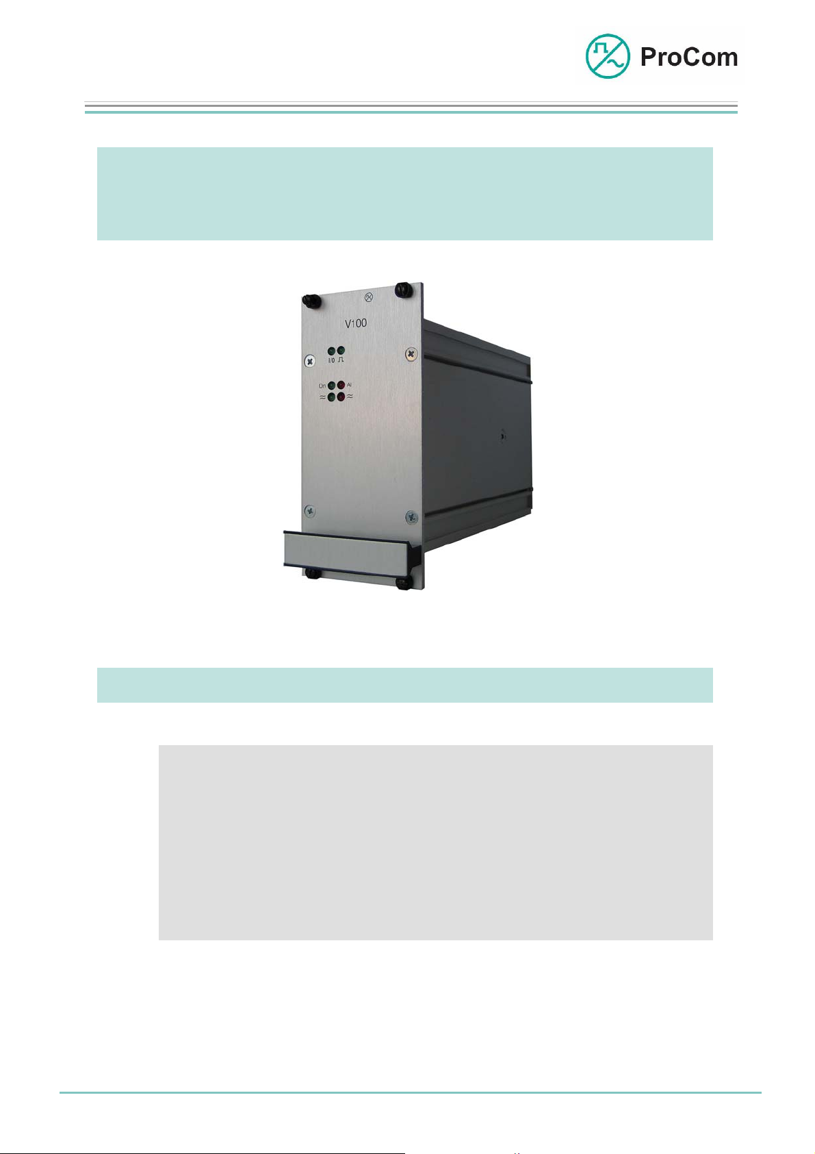
V100
100 Watt Amplifier
Fig. V100 (L- No. 2.510)
At a Glance:
The amplifier module V100 supplies an output of 100 W
at 100 V output voltage.
Up to 17 amplifier modules (17 x 100 W) can be used in a DVS-21 system.
• Amplifier for low frequency (LF) signals with max. output of
100 Watt
• Standard output voltage of 100 V (optionally also 50 V or 70 V)
• Short-circuit resistant
• Integrated wire breakage and short-circuit monitoring
(according to equipment level 2 of the Deutsche Bahn AG)
Date:
16.03.2009
Page:
1/5
© 2008 ProCom, All rights and technical changes reserved
Author: HS Document-No.:
DB_V100_2510_01
Page 2
Data Sheet
A
V
r
V
V
V100
Amplifier Slide-in Panel
Function Description:
WPS-04
WPS-08
DTA-012 030/ 048/ 066/ 084/ 114
2TW *
TG01
4LSL
LK2 .. 5
LS 1
LS n
LS 2
SV01
CPU1 4NS
100
LK1
DVS-21
DSS1
* TW = Twin Wire
100
100
Disaste
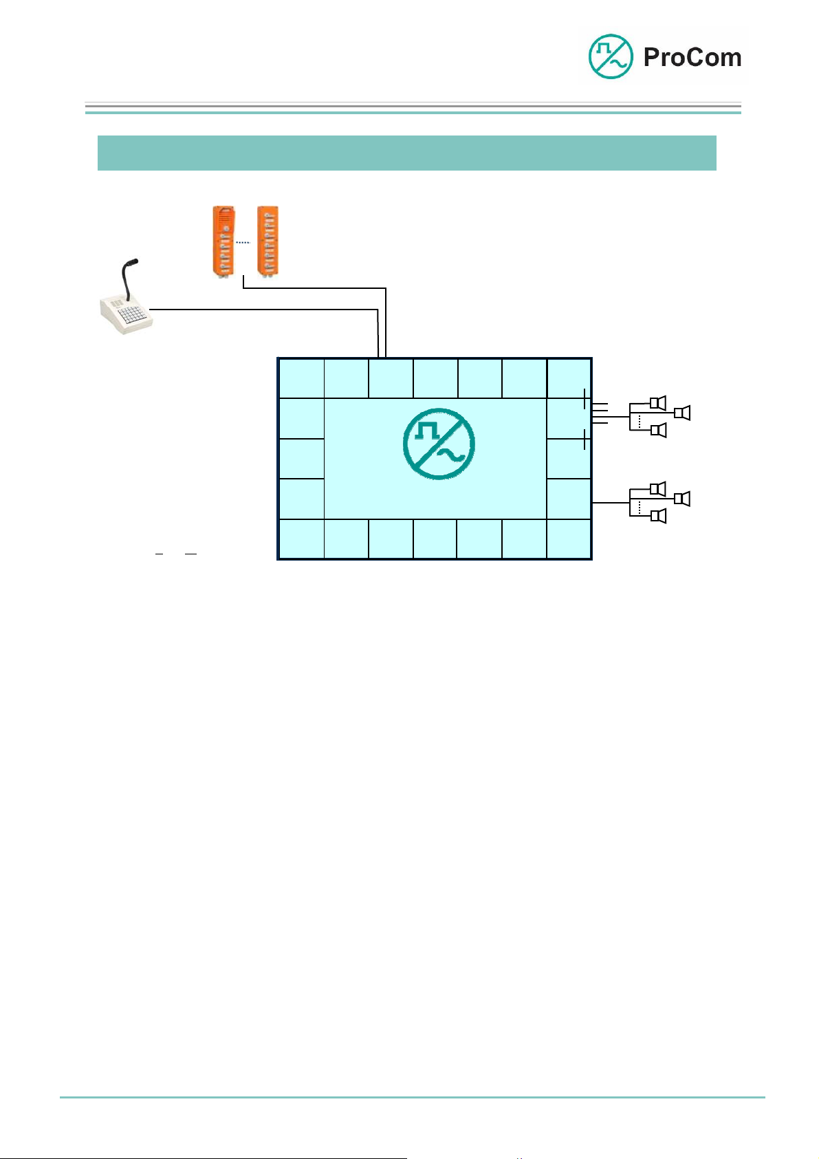
Application example, public address
The V100 amplifies low frequency (LF) signals of the DVS-21 system. The maximum output is 100 W. Different sources can act as LF signal, e.g. call stations
connected to the 4NSA (manual public address) or the speech memory module
DSS1 (automatic public address).
The amplifier outlet can be switched directly to a loudspeaker circuit or to different loudspeaker circuits using the modules 4LSL or 4IOS. If a TG01 is used in
addition to the 4LSL, then the individual loudspeaker circuits can be monitored for
impedance deviations.
If an amplifier fails then an emergency/disaster amplifier can take over its function.
The V100 is divided into function groups:
1) Control
2) Codec
3) Digital amplifier
4) Filter
5) Output
6) Disaster switch
7) Wire breakage or short-circuit monitoring
LS 1
LS 2
LS n
Date:
16.03.2009
Page:
2/5
Author: HS Document-No.:
© 2008 ProCom, All rights and technical changes reserved
DB_V100_2510_01
Page 3

Data Sheet
g
per
g
g
V100
Amplifier Slide-in Panel
The following block diagram illustrates the functionality:
V100
I
n
A
d
n
i
z
c
e
a
i
t
g
i
e
o
n
Impedanzüberwachung
Impedance Monitorin
(Z)
Potential-
Ausgangs-
Output
Transformer
rtragerÜbe
Potential
trennung
Se
Filter
a-
Codec
Codec
Meldung
Signal
Test Signal
Testton
LF
NF
Digital
ital-
Dig
Amplifier
Verstärker
C
S
O
t
e
N
u
e
T
P
r
C
P
M
R
u
C
M
n
O
g
+5V
GND
-5V
KS
BUS
L
Impedance Monitorin
Impedance Monitorin
1) Control
A microprocessor regulates timing control between the PCM bus and the
module, controls message input and output and generates the audio signal required for impedance monitoring.
2) Codec
The codec converts the incoming digital signal into analogue LF and passes
this to the opto-coupler for potential separation.
3) Digital Amplifier
The digital amplifier amplifies the potential-separated LF signal.
The operating voltage of 48 V required for this is fused.
4) Filter
The low-pass filter filters the amplified signal and passes it on to the output
transformer.
V out
VH in
Havarie-
Disaster
Eingang
Input
50/70/100V
Relay 1
Relais 1
Relay 2
Relais 2
48V
(Short-circuit Secure)
rzschlussfest)(Ku
Block diagram V100
-48V
+0V
Date:
16.03.2009
Page:
3/5
© 2008 ProCom, All rights and technical changes reserved
Author: HS Document-No.:
DB_V100_2510_01
Page 4

Data Sheet
V100
Amplifier Slide-in Panel
5) Output
The output signal is adjusted per default to 100 V. Optionally, an adjustment to
50 V or 70 V can be made. For this all that is needed is that a jumper be soldered onto the backplane of the DVS-21 system. The signal is switched over
the closed circuit contact of relay 1.
6) Disaster Switch
In the case of a disruption, depending on the system, one or multiple amplifi-
ers can be used as emergency amplifiers. One amplifier can assume the
disaster function for up to 6 amplifiers. In the case of a disruption the damage relay (relay 2) and the output relay (relay 1) of the defective V100 drop
out. The loudspeaker circuit of the failed amplifier is connected with the output of the disaster amplifier over the normally closed contact of relay 1. Allocation of the disaster amplifier is done using solder bridges on the backplane.
7) Wire Breakage and Short-Circuit Monitoring
Output voltage and current in the loudspeaker line are measured for wire
breakage and short-circuit monitoring. An error message is issued if programmed limit values are underrun or exceeded. A TG01 and a 4LSL are
required for more precise monitoring of impedance in individual loudspeaker
circuits.
The Front Plate Symbols and their Meaning:
The System Blinker
Addressing from processor taking place
I/O Input/Output
BUS input works as push-pull operation with the system blinker
BUS output works as push-push operation with the system
blinker
On Public Address Status Display
AL Alarm Signal LED
≈ (green) Output 50/70/100 V Modulation Display
Date:
16.03.2009
≈ (red) Output 50/70/100 V Overmodulation
Page:
4/5
Author: HS Document-No.:
© 2008 ProCom, All rights and technical changes reserved
DB_V100_2510_01
Page 5

Data Sheet
V100
Amplifier Slide-in Panel
Technical Data:
Operating Voltage: 48 V (power level)
Operating Voltage: +/-5 V (control)
Idle Current (48 V): ca. 70 mA
Operational Current (48 V): Max. 2.7 A (100 W sine)
Operational Current (+5 V): Max. 30 mA
Operational Current (-5 V): Max. 9 mA
Power Output: 100 W
Distortion Factor: ca. 1% at maximum load
Output Voltage: As required 50 V / 70 V /100 V
Temperature Range: 0 °C to 45 °C
Electrically Isolated from Output!
Protection Against Short Circuit and Stress Peaks!
Weight: 1600 g
Date:
16.03.2009
Page:
5/5
© 2008 ProCom, All rights and technical changes reserved
Author: HS Document-No.:
DB_V100_2510_01
 Loading...