

Page 1
Data Sheet
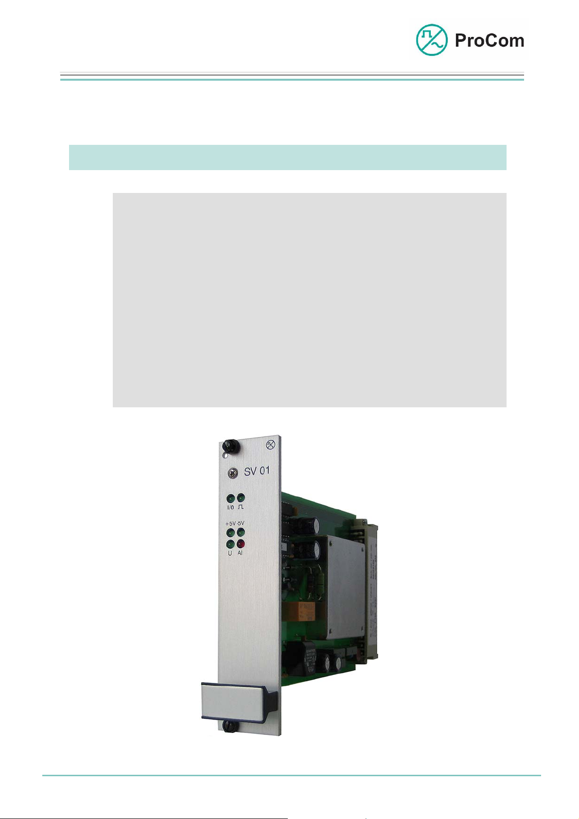
SV01
Power Supply Module
The DC/DC power supply module supplies the entire DVS-21 with +/- 5 V. It is set up
for an input voltage of 36 V – 75 V.
At a Glance:
• DC/DC power supply to the DVS-21
• Display and forwarding of group malfunction signals
• Monitoring of the processor module CPU1
• Monitoring of the input and output voltage
• Floating contacts for external signals (e.g. power supply)
• Temperature monitoring
• Passive cooling
Fig. SV01 (L- No. 2100)
Date:
25.03.2009
Page:
1/4
© 2008 ProCom, All rights and technical changes reserved
Author: HS Document-No.:
DB_SV01_2100_01
Page 2
Data Sheet
SV01
Power Supply Module
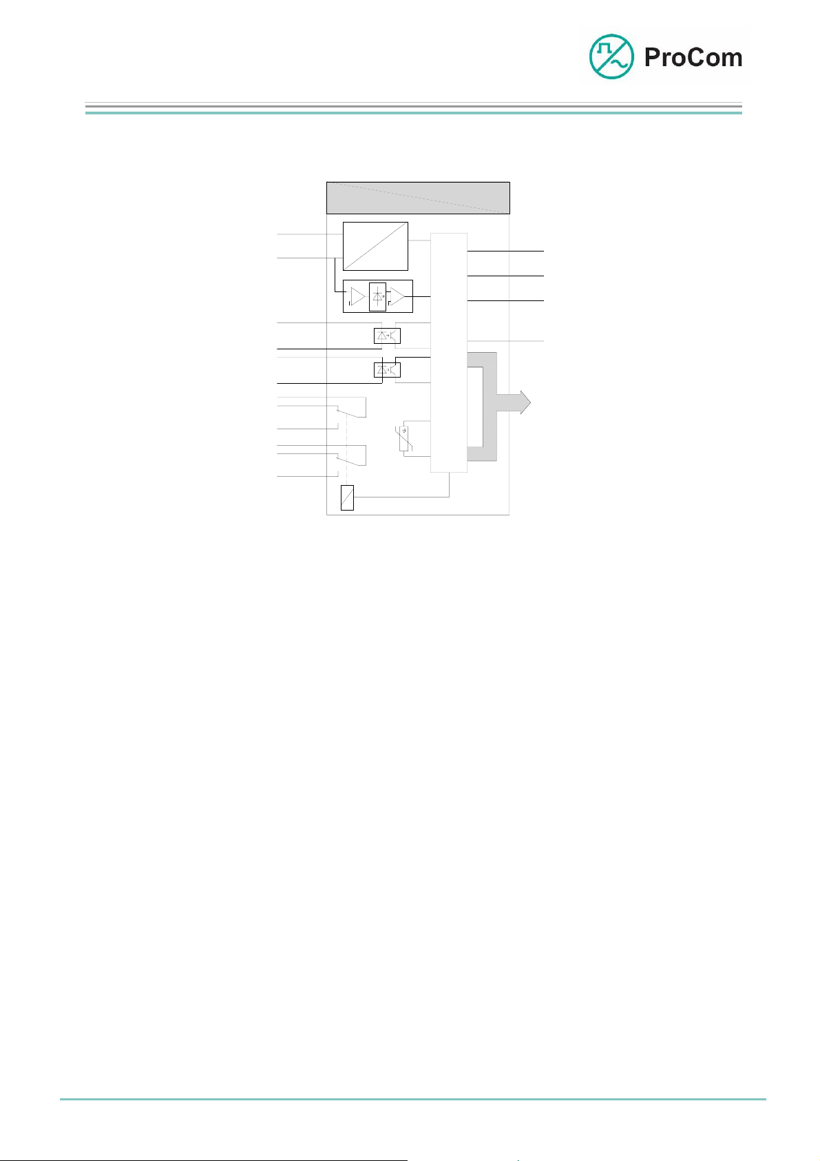
The principle functions of the SV01 are illustrated in the following block diagram.
SV01
+SV01 (0V)
-SV01 (-48V)
-OK1
OK1
-OK2
OK2
SV mk2
SV rk2
SV ak2
SV mk1
SV rk1
SV ak1
48V DC
-48V
+/- 5V DC
-5V
U<
NTC
+5V
GND
-5V
KS 01
BUS
Block diagram SV01
The module receives the input voltage (nominal 48 V/60 V DC) through the
backplane of the basic unit (GG1 or GG2). The SV01 supplies the entire system with
an output voltage of +/-5 V through the backplane.
A group malfunction signal can be passed potential-free to the outside world over the
error relay with two change-over contacts.
The processor module CPU1 is monitored by the SV01. The CPU1 cyclically sends
status frames which are evaluated per default by the power supply module. If the
CPU1 becomes inoperational or defective then these frames are absent; the alarm
LED lights up and the malfunction signal relay drops out.
Signals can be passed to the DVS-21 over the two potential-free opto-coupler inputs
(e.g. for power supply monitoring).
The temperature on the card is determined using NTC and passed to the CPU1.
Optionally, the reading can be queried by the processor module.
For monitoring of low voltage the 48 V input voltage is measured on the SV01 and
the reading is also passed to the CPU1. There, as option, it can be evaluated.
The various operational statuses are displayed on the front plate LEDs.
Date:
25.03.2009
Page:
2/4
© 2008 ProCom, All rights and technical changes reserved
Author: HS Document-No.:
DB_SV01_2100_01
Page 3

Data Sheet
)
SV01
Power Supply Module
The Symbols on the Front Plate and their Meaning:
The System Blinker
Addressing from processor taking place (refer to the CPU1 data
sheet for more information
I/O Input/Output
BUS output works as push-push operation with the system blinker
BUS input works as push-pull operation with the system blinker
+5 V Output Voltage
+5 V supply voltage available for the modules
-5 V Output Voltage
-5 V supply voltage available for the modules
Al Malfunction Signal (Alarm)
Group malfunction signals
U Input Voltage
48 V available
Technical Data:
Input Voltage: From 36 V to 75 V, nominal 48 V DC
Output Voltage: +/-5 V
Idle Current at 48 V: 56 mA
Load Current: Max. 1 A
Temperature Range: 0 °C to 45 °C
Date:
25.03.2009
Page:
3/4
Author: HS Document-No.:
© 2008 ProCom, All rights and technical changes reserved
DB_SV01_2100_01
Page 4

Data Sheet
SV01
Power Supply Module
Interfaces: 2 independent opto-coupler inputs (OK1 and OK2)
1 relay with 2 change-over contacts
(work and idle contact)
Weight: 300 g
Installation Height: 3HE
Installation Width: 6TE
Malfunction Signal Optional
for Excess Voltage:
Temperature Optional
Monitoring:
Date:
25.03.2009
Page:
4/4
© 2008 ProCom, All rights and technical changes reserved
Author: HS Document-No.:
DB_SV01_2100_01
 Loading...