

Page 1
1
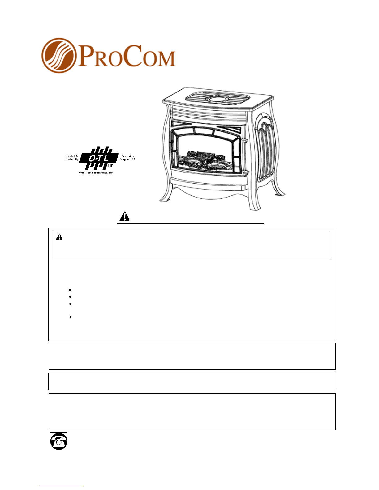
Vent-free Gas Stove
MODEL NO. SSU220RHN-GB & SSU220RHL-GB
Questions about installation, operation, or troubleshooting? Before returning to your retailer, call our customer
service department toll-free at (877)886-5989
PRGHO[[EMSHJ
PC-SSU220R653-0805
This appliance may be installed in an aftermarket, permanently located manufactured
(mobile) home, where not prohibited by local codes. This appliance is for use with
the type of gas indicated on the rating plate only. This appliance is not convertible for
use with other gases.
CAUTION - FOR YOUR SAFETY
WARNING: IF THE INFORMATION IN THIS MANUAL IS NOT FOLLOWED
EXACTLY, A FIRE OR EXPLOSION MAY RESULT CAUSING PROPERTY
DAMAGE, PERSONAL INJURY, OR LOSS OF LIFE.
--
Do not store or use gasoline or other ammable vapors and liquids in vicinity
of this or any other appliance.
WHAT TO DO IF YOU SMELL GAS
Do not try to light any appliance.
Do not touch any electrical switch; do not use any phone in your building.
Immediately call your gas supplier from a neighbor’s phone. Follow the
gas supplier’s instructions.
If you cannot reach your gas supplier, call the re department.
-- Installation and service must be performed by a qualied installer, service
agency or the gas supplier.
This is an unvented gas-red heater. It uses air (oxygen) from the room in which it is
installed. Provisions for adequate combustion and ventilation air must be provided.
Refer to Air For Combustion and Ventilation section on page 6 of this manual.
INSTALLER: DO NO DISCARD THIS MANUAL – LEAVE FOR HOMEOWNER’S
FUTURE REFERENCE
Page 2
2
2
TABLE OF CONTENTS
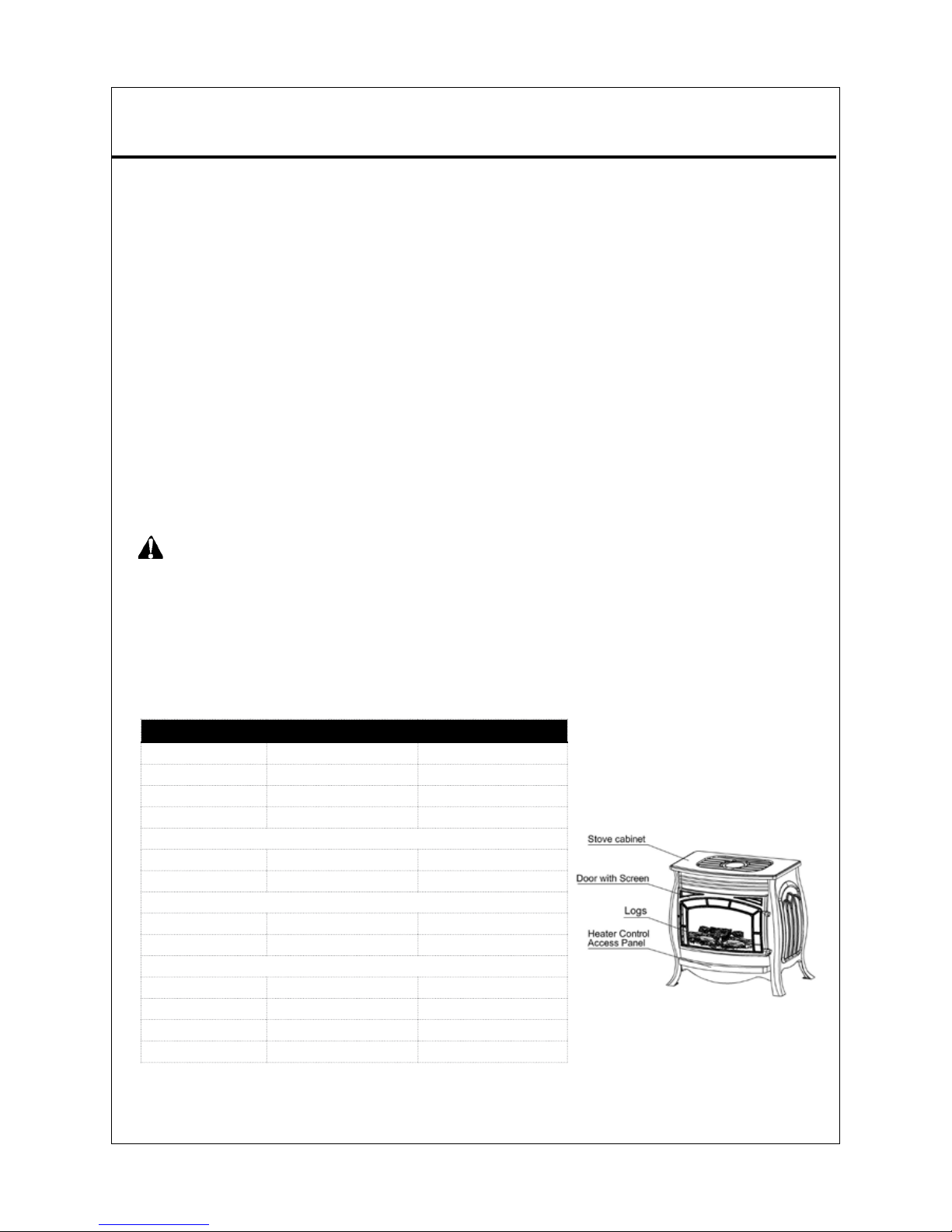
Figure 1- Vent - Free Gas Stove
S[[EMSHJ
Important Safety Information ...........................................................................................................................3
Air for Combustion & Ventilation ....................................................................................................................6
Product Features ..............................................................................................................................................8
Preparing for Installation .................................................................................................................................8
Installation .....................................................................................................................................................10
Connecting To Gas Supply ......................................................................................................................10
Checking Gas Connections .....................................................................................................................11
Log Placement .........................................................................................................................................13
Operating Heater .............................................................................................................................................14
Care and Maintenance ..................................................................................................................................18
Troubleshooting .............................................................................................................................................20
Replacement Parts ..........................................................................................................................................23
WARNING: READ THE INSTALLATION & OPERATION INSTRUCTIONS
BEFORE USING THIS APPLIANCE
IMPORTANT: Read instructions and warnings carefully before starting installation. Failure to fol-
low these instructions may result in a possible re hazard and will void the warranty.
PRODUCT SPECIFICATIONS
MODEL NO
SSU220RHL-GB SSU220RHN-GB
Btu (Variable) 22,000 22,000
Gas Type LP Gas Natural Gas
Ignition Automatic or Electronic Automatic or Electronic
Manifold Pressure 8” W.C. 3” W.C.
Inlet Gas Pressure (In. of water)*
Maximum 14 in. 10.5 in.
Minimum 11 in. 5 in.
Dimensions, Inches (H×W×D)
Heater 26 1/8” × 28” ×16 7/8” 26 1/8” × 28” ×16 7/8”
Carton 31 1/8”×31 3/8” ×20 1/2” 31 1/8”×31 3/8” ×20 1/2”
Weight, lbs
Stove 73 73
Shipping 85 85
Volts 120 120
Watts 19 19
*For purposes of input adjustment
TABLE OF CONTENTS
Page 3
333
IMPORTANT SAFETY INFORMATION
IMPORTANT: Read instructions and warnings carefully before starting installation. Failure to follow these instructions
may result in possible electric shock or re hazard and will void the warranty. Improper use of this heater can cause serious injury or death from burns, re, explosion, electrical shock, and carbon monoxide poisoning. Refer to this manual
for correct installation and operat ional procedures. For assistance or additional information consult a qualied
installer, service agency, local gas supplier, or customer service.
Do not store or use gasoline or other ammable vapors and liquids in the vicinity of this or any other appliance.
WHAT TO DO IF YOU SMELL GAS
Do not try to light any appliance.
Do not touch any electrical switch; do not use any phones in your building.
Immediately call your gas supplier from a neighbor’s phone. Follow the gas supplier’s instructions.
If you cannot reach your gas supplier, call the re department.
Installation and service must be performed by a qualied installer, service agency, or local gas supplier.
WARNING: This is an unvented gas-red heater. It uses air (oxygen) from the room in which it is installed.
Provisions for adequate combustion and ventilation air must be provided. Refer to Air For Combustion and Ventilation section on page 6 of this manual.
This appliance is only for use with the type of gas indicated on the rating plate. This appliance is not
convertible for use with other gases.
DANGER: Carbon monoxide poisoning may lead to death!
WARNING: When used without fresh air, heater may give off CARBON MONOXIDE, an odorless, poisonous gas.
DO NOT INSTALL HEATER UNTIL ALL NECESSARY PROVISIONS ARE MADE FOR COMBUSTION AND
VENTILATION AIR. CONSULT THE WRITTEN INSTRUCTIONS PROVIDED WITH THE HEATER FOR IN
FORMATION CONCERNING COMBUSTION AND VENTILATION AIR. IN THE ABSENCE OF INSTRUCTIONS.
REFER TO THE NATIONAL FUEL GAS CODE. ANSI Z223. 1. SECTION 5.3 OR APPLICABLE LOCAL CODES.
This heater is equipped with a PILOT LIGHT SAFETY SYSTEM designed to turn off the heater if not enough
fresh air is available.
DO NOT TAMPER WITH PILOT LIGHT SAFETY SYSTEM! If heater shuts off, do not re-light until you provide
fresh air. If heater keeps shutting off have it serviced. Keep burner and control compartment clean.
CARBON MONOXIDE
Early signs of carbon monoxide poisoning resemble the u with headache, dizziness and/or nausea. If you have
these signs, heater may not be working properly. Get fresh air at once! Have heater serviced. Some people
pregnant women, persons with heart or lung disease, anemia, those under the inuence of alcohol, and those at
high altitude - are more affected by carbon monoxide than others.
NATURAL AND PROPANE/LP GAS
Natural and Propane/LP gases are odorless. An odor-making agent is added to the gas. The odor helps you detect
a gas leak. However, the odor added to the gas can fade. Gas may be present even though no odor exists.
WARNING: Any change to this replace or its controls can be dangerous.
WARNING: Model SSU220RHN is equipped for Natural gas. Field conversion is not permitted. Model
SSU220RHL is equipped for propane gas. Field conversion is not permitted.
•
•
•
•
IMPORTANT SAFETY INFORMATION
Page 4

4
WARNING: Do not allow fans to blow directly into the heater. Avoid any drafts that alter burner ame patterns
including ceiling fans. Altered burner patterns can cause sooting.
WARNING: Do not use a blower insert, heat exchanger insert, or other accessory not approved for use with
this heater.
WARNING: Due to high temperatures, the appliance should be located out of trafc and away from furniture
and draperies.
WARNING: Heater becomes very hot when running. Keep children and adults away from hot surfaces to avoid
burns or clothing ignition. Heater will remain hot for a time after shutoff. Allow surfaces to cool before touching.
WARNING: Do not place clothing or other ammable material on or near the appliance. Never place any ob-
jects in the heater.
WARNING: Carefully supervise young children when they are in the room with the heater.
WARNING: You must operate this heater with the heater door and screen in place. Make sure the heater door
and screen is in place before running heater.
WARNING: Keep the appliance area clear and free from combustible materials, gasoline, and other ammable
vapors and liquids.
When using electrical appliances, basic precautions should always be followed to reduce the risk of re, electric shock,
and injury to persons, including the following:
1. Do not use this appliance with any gas other than the type indicated on the rating plate.
2. Do not place Propane/LP supply tank(s) inside any structure. Store Propane/LP supply tank(s) outdoors.
3. If you smell gas
Shut off gas supply.
Do not try to light any appliance.
Do not touch any electrical switch; do not use any phone in your building.
Immediately call your gas supplier from a neighbor’s phone. Follow the gas supplier’s instructions.
If you can not rea ch y our gas supplier, call the re department.
4. Do not install this heater in a bedroom or bathroom.
5. Do not us e thi s hea ter a s a w ood-burning heater. Use only the logs provided with the heater.
6. Do not add extra logs or ornaments such as pine cones, vermiculite, or rock wool. Using these added items can
cause sooting. Do not add lava rock around base. Rock and debris could fall into the control area of heater. After
servicing, always replace screen before operating heater.
7. This heater is designed to be smokeless. If logs ever appear to smoke, turn heater off and call a qualied
service person. Note: During initial operation, slight smoking could occur due to log curing and heater burning
manufacturing residues.
8. To prevent the creation of soot, follow the instructions in
Care and Maintenance.
9. This heater needs fresh air ventilation to run properly. This heater has an Oxygen Depletion Sensing (ODS)
safety shutoff system. The ODS shuts down the heater if not enough fresh air is available. See Air for Combus-
tion and Ventilation, pages 6 through 7. If heater keeps shutting off, see Troubleshooting, page 20.
•
•
•
•
•
Page 5

5
10. Keep all air openings in front and bottom of heater clear and free of debris. This will ensure enough air for proper
combustion.
11. If heater shuts off. Do not relight until you provide fresh, outside air. If heater keeps shutting off, have it serviced.
12. Do not run heater:
Where ammable liquids or vapors are used or stored.
Under dusty conditions.
13. Before using furniture polish, wax, carpet cleaner, or similar products, turn heater off. If heated, the vapors from
these products may create a white powder residue within burner box or on adjacent walls or furniture.
14. Do not use this heater to cook food or burn paper or other objects.
15. Do not use heater if any part has been under water. Immediately call a qualied service technician to inspect
the heater and to replace any part of the control system and any gas control which has been under water.
16. Turn off and unplug heater and let cool before servicing. Only a qualied service person should service and repair
heater.
17. Operating heater above elevations of 4,500 feet could cause pilot outage.
18. Do not operate heater if any log is broken. Do not operate heater if a log has a chip (dime-sized or larger).
19. To prevent performance problems, do not use Propane/LP fuel tank of less than 100 lbs. (46 kg) capacity
.
•
•
QUALIFIED INSTALLING AGENCY
Installation and replacement of gas piping, gas utilization equipment or accessories and repair and servicing of
equipment shall be performed only by a qualied agency. The term “qualied agency” means any individual, rm,
corporation, or company that either in person or through a representative is engaged in and is responsible for:
The installation, testing, or replacements of gas piping or
The connection, installation, testing, repair, or servicing of equipment; that is experienced in such work, that
is familiar with all precautions required, and that has complied with all the requirement of the authority having jurisdiction.
a)
b)
Page 6
66
WARNING: This heater shall not be installed in a conned space or unusually tight construction unless
provisions are provided for adequate combustion and ventilation. Read the following instructions to insure
proper fresh air for this and other fuel-burning appliances in your home.
Providing Adequate Ventilation
The following are excerpts from National Fuel Gas Code, NFPA 54/ANSI Z223.1, Section 5.3, Air for Combustion
and Ventilation. All spaces in homes fall into one of the three following ventilation classications:
1. Unusually Tight Construction
2. Unconned Space
3. Conned Space
The information on pages 6 through 7 will help you classify your space and provide adequate ventilation.
Conned and Unconned Space
The National Fuel Gas Code, ANSI Z223.1 denes a conned space as a space whose volume is less than 50
cubic feet per 1,000 Btu per hour (4.8 m3 per kw) of the aggregate input rating of all appliances installed in that
space and an unconned space as a space whose volume is not less than 50 cubic feet per 1,000 Btu per hour
(4.8 m3 per kw) of the aggregate input rating of all appliances installed in that space. Rooms connecting directly
with the space in which the appliances are installed*, through openings not furnished with doors, are considered
a part of the unconned space.
This heater shall not be installed in a conned space or unusually tight construction unless provisions are pro-
vided for adequate combustion and ventilation.
* Adjoining rooms are connecting only if there are doorless passageways or ventilation grills between them.
Unusually Tight Construction
The air that leaks around doors and windows may provide enough fresh air for combustion and ventilation. However, in buildings of unusually tight construction, you must provide additional fresh air.
Unusually tight construction is dened as construction where:
Walls and ceilings exposed to the outside atmosphere have a continuous water vapor retarder with a rating
of one perm (6×10
-11
kg per pa-sec-m2) or less with openings gasketed or sealed and
Weather stripping has been added on operable windows and doors and
Caulking or sealants are applied to areas such as joints around window and door frames, between sole
plates and oors, between wall ceiling joints, between wall panels, at penetrations for plumbing, electrical,
and gas lines, and at other openings.
If your home meets all of the three criteria above, you must provide additional fresh air. See “Ventilation Air From
Outdoors”. If your home does not meet all of the three criteria above, proceed to Determining Fresh-Air Flow For
Heater Location.
Determining if You Have a Conned or Unconned Space
Use this worksheet to determine if you have a conned or unconned space.
Space: Includes the room in which you will install heater plus any adjoining rooms with doorless passageways
or ventilation grills between the rooms.
1. Determine the volume of the space
Length×Width×Height= cu.ft. (volume of space)
Example: Space size 20ft. (length)×16ft. (width)×8ft. (ceiling height)=2560cu. ft. (volume of space)
If additional ventilation to adjoining room is supplied with grills or openings, add the volume of these rooms
to the total volume of the space.
a)
b)
c)
AIR FOR COMBUSTION AND VENTILATION
Page 7
7
Figure 2 - Ventilation Air
from Inside Building
2. Divide the space volume by 50 cubic feet to determine the maximum Btu/Hr the space can support.
(volume of space)÷50 cu. ft.=(Maximum Btu/Hr the space can support).
3. Add the Btu/Hr of all fuel-burning appliances in the space.
Vent-free heater
Gas water heater*
Gas furnace
Vented gas heater
Gas heater logs
Other gas appliances* +
Total =
*Do not include direct-vent gas appliances. Direct-vent draws combustion air from the outdoors and vents to the outdoors.
4. Compare the maximum Btu/Hr the space can support with the actual amount of Btu/Hr used.
Btu/Hr (maximum the space can support)
Btu/Hr (actual amount of Btu/Hr used)
Example : 51,200 Btu/Hr(maximum the space can support)
56,000 Btu/Hr(actual amount of Btu/Hr used)
The space in the above example is a conned space because the actual Btu/Hr used is more than the maximum
Btu/Hr the space can support.
You must provide additional fresh air. Your options are as follows:
Rework worksheet, adding the space of an adjoining room. If the extra space provides an unconned
space, remove door to adjoining room or add ventilation grills between rooms. See Ventilation Air From
Inside Building.
Vent room directly to the outdoors. See Ventilation Air From Outdoors .
Install a lower Btu/Hr heater if lower Btu/Hr size makes room unconned.
WARNING: If the area in which the heater may be operated is smaller than that dened as an unconned space
or if the building is of unusually tight construction, provide adequate combustion and ventilation air by one of the
methods described in the National Fuel Gas Code, ANSI Z223.1/NFPA 54, Air for Combustion and Ventilation, or
applicable local codes.
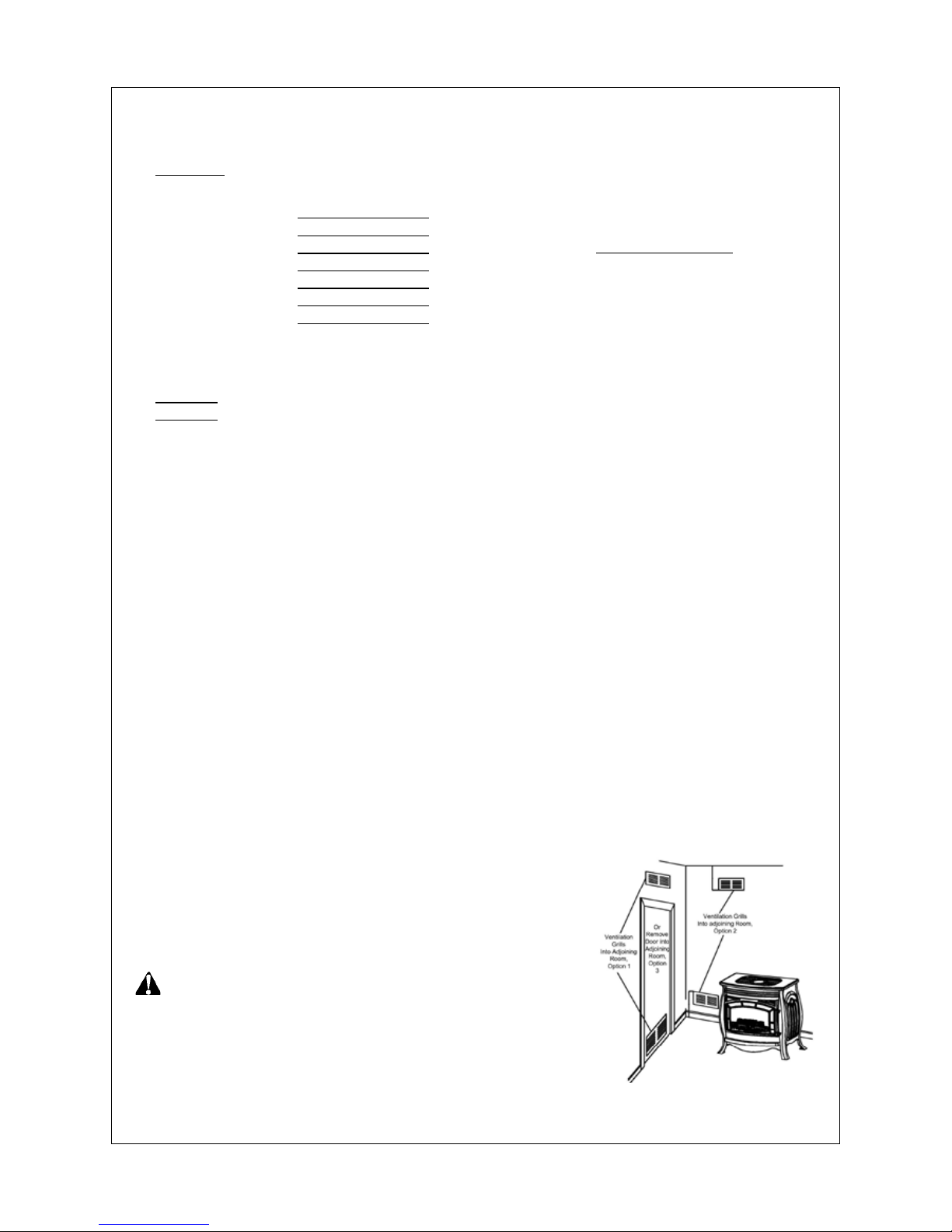
Ventilation Air From lnside Building
This fresh air would come from an adjoining unconned space. When ventilating to an adjoining unconned
space, you must provide two permanent openings: one within 12 inches of the ceiling and one within 12 inches
of the oor on the wall connecting the two spaces (see options 1 and 2, Figure 2). You can also remove the door
into the adjoining room (see option 3, Figure 2). Follow the National Fuel Gas Code. NFPA 54/ANSI Z223.1,
Section 5.3, Air for Combustion and Ventilation for required size of ventilation grills or ducts.
a)
b)
c)
Example:
Gas water heater 30,000 Btu/Hr
Vent-free heater + 26,000 Btu/Hr
Total = 56,000 Btu/Hr
Btu/Hr
Btu/Hr
Btu/Hr
Btu/Hr
Btu/Hr
Btu/Hr
Btu/Hr
Ventilation Air From Outdoors
Provide extra fresh air by using ventilation grills or ducts. You must provide
two permanent openings: one within 12 inches of the ceiling and one within
12 inches of the oor. Connect these items directly to the outdoors or spaces open to the outdoors. These spaces include attics and crawl spaces.
Follow the National Fuel Gas Code, NFPA 54/ANSI Z223.1, Section 5.3, Air
for Combustion and Ventilation for required size of ventilation grills or ducts.
IMPORTANT: Do not provide openings for inlet or outlet air into attic if
attic has a thermostat-controlled power vent. Heated air entering the attic
will activate the power vent. Rework worksheet, adding the space of the ad-
joining unconned space. The combined spaces must have enough fresh
air to supply all appliances in both spaces.
Page 8
8
PRODUCT FEATURES
Safety Pilot
This heater has a pilot with an Oxygen Depletion Sensing (ODS) safety shutoff system. The ODS/pilot shuts off
the heater if there is not enough fresh air.
Automatic Ignition System
This heater is equipped with an automatic control system. This system requires no matches, or batteries to light
heater.
Thermostatic Heat Control Module
This heater has a control module with a thermostat sensing bulb. Set
temperature with remote control. This results in the greatest heater comfort and may result in lower gas bills.
Manual Override Control System
This heater has two operation functions: Remote Control and Manual
Override Control. The Remote Control has a transmitter, which requires
three AAA batteries and electric power outlet to operate. In the event of
a power outage, you can operate the heater by manual override.
LOCAL CODES
This heater is designed for vent free operation. Some state and local codes
prohibit the use of vent-free gas heaters.
lnstall and use heater with care. Follow all local codes. In the absence of
local codes, use the latest edition of The National Fuel Gas Code, ANSI
Z223.1, also known as NFPA 54*.
*Available from:
American National Standards lnstitute, lnc.
1430 Broadway
New York, NY 10018
National Fire ProtectionAssociation, lnc.
1 Batterymarch Park
Quincy, MA 02269-9101
State of Massachusetts: The installation must be made by a licensed
plumber or gas tter in the Commonwealth of Massachusetts.
Sellers of unvented propane or natural
gas-red supplemental room heaters
shall provide to each purchaser a copy
of 527 CMR 30 upon sale of the unit.
In the state of Massachusetts, unvent-
ed propane or natural gas-red space
heaters shall be prohibited in bedrooms
and bathrooms.
In the State of Massachusetts the
gas cock must be a “T” handle type.
The State of Massachusetts requires
that a exible appliance connector
cannot exceed three feet in length.
PREPARING FOR INSTALLATION
Before beginning assembly or operation of the product, make sure all parts are present. Compare parts with package contents list and diagram above. If any part is missing or damaged, do not attempt to assemble, install or operate the product. Contact customer service for replacement parts.
Estimated Assembly Time: ____
Tools Required for Assembly:
Before installing heater, make sure you have the items listed below.
piping (check local codes)
sealant (resistant to natural gas and propane/LP gas)
equipment shutoff valve*
test gauge connection*
sediment trap
tee joint
pipe wrench
exible gas hose. (Check local codes)
*A CSA design-certied equipment shutoff valve with 1/8 in NPT tap is an acceptable alternative to test gauge connection. Purchase the optional
CSA design-certied equipment shutoff valve from your dealer.
•
•
•
•
•
•
•
•
Page 9

9
S[[EMSHJ
UNPACKING
1. Remove top inner pack.
2. Tilt carton so that stove is upright.
3. Remove protective side packaging.
4. Slide stove out of carton.
5. Remove protective plastic wrap.
6. Rotate door handle and open door.
7.
Logs # 1, 3, 4, 5, & 6 are under heater.
8. Carefully unwrap logs.
9. Check for any shipping damage. If stove or logs are damaged,
promptly inform Customer Care.
Figure 3 - Ventilation Air from Outdoors
Water Vapor: A By-product Of Unvented Room Heaters
Water vapor is a by-product of gas combustion. An unvented room heater produces approximately one (1) ounce
(30ml) of water for every 1,000 BTUs (.3KWs) of gas input per hour. Unvented room heaters are recommended
as supplemental heat (a room) rather than a primary heat source (an entire house). In most supplemental heat
application, the water vapor does not create a problem. In most applications, the water vapor enhances the low
humidity atmosphere experience during cold weather.
The following steps will help ensure that water vapor does not become a problem.
1. Be sure the heater is sized properly for the application, including ample combusion air and circulation air.
2. If high humidity is experienced, a dehumidier may be used to help.
NOTICE: This heater is intended for use as supplemental heat. Use this heater along with your primary heat-
ing system. Do not install this heater as your primary heat source. If you have a central heating system, you
may run the system’s circulating blower while using heater. This will help circulate the heat throughout the
house. In the event of a power outage, you can use this heater as your primary heat source.
IMPORTANT: Installing heater in rooms without enough ventilation air may cause mildew to form from too
much moisture. See Air for Combustion and Ventilation, pages 6 and 7.
WARNING: A qualied service person must install heater. Follow all local codes.
WARNING: Electrical Grounding Instructions
This appliance is equipped with a three-prong (grounding) plug for your protection against shock hazard
and should be plugged directly into a properly grounded three-prong receptacle.
WARNING:Never install the heater
in a bedroom or bathroom
in a recreational vehicle
where curtains, furniture, clothing, or other ammable objects are less than 42 inches from the front, top, or
sides of the heater
in high trafc areas
in windy or drafty areas
WARNING: Maintain the minimum clearances. If you can, provide greater clearances from oor, ceiling, and
adjoining side and back walls.
CAUTION: This heater creates warm air currents. These currents move heat to wall surfaces next to heater.
Installing heater next to vinyl or cloth wall coverings or operating heater where impurities (such as tobacco
smoke, aromatic candles, cleaning uids, oil or kerosene lamps, etc.) in the air exist as it may discolor
walls.
Check Gas Type
Be sure your gas supply is right for your heater. Otherwise, call the dealer where you bought the heater for the
proper type heater.
•
•
•
•
•
Page 10

10
CONNECTING TO GAS SUPPLY
WARNING: A qualied service technician must connect heater to gas supply. Follow all local codes.
WARNING: This appliance requires a 3/8 inch NPT (National Pipe Thread) inlet connection to the pressure
regulator.
WARNING: Never connect heater to private (non-utility) gas wells. This gas is commonly known as wellhead gas.
WARNING: Do not overtighten gas connections.
CAUTION: Use only new, black iron or steel pipe. Internally-tinned copper tubing may be used in certain ar-
eas. Check your local codes. Use pipe of 1/2 inch diameter or greater to allow proper gas volume to heater.
If pipe is too small, undue loss of pressure will occur.
CAUTION: Never connect heater directly to the gas supply. This heater requires an external regulator (not
supplied). lnstall the external regulator between the heater and gas supply.
CAUTION: Avoid damage to regulator. Hold gas regulator with wrench when connecting into gas piping
and/or ttings.
CAUTION: Use pipe joint sealant that is resistant to gas (PROPANE or NATURAL GAS).
Clearances To Combustibles
Carefully follow the instructions below. This stove is a freestanding
unit designed to set directly on the oor.
IMPORTANT: You must maintain minimum wall and ceiling
clearances during installation. The minimum clearances are shown
in Figure 4. Measure from outermost point of stove top.
If heater is installed directly on carpeting, tile or other combustible
material, other than wood ooring, the heater shall be installed on
a metal or wood panel extending the full width and depth of the
heater.
Minimum Wall and Ceiling Clearances (See Figure 4)
Clearances from outermost point of stove top to any combus-
tible side wall should not be less than 12 inches.
Clearances from outermost point of stove top to any combus-
tible back wall should not be less than 6 inches (lncludes corner
installations).
Clearances from the stove top to the ceiling should not be less
than 48 inches.
a)
b)
c)
INSTALLATION
Figure 4 - Minimum Clearance
to Wall and Ceiling
Page 11

11
FOR PROPANE UNITS ONLY
The installer must supply an external regulator (see Figure 5). The external
regulator will reduce incoming gas pressure. If you do not reduce incoming
gas pressure, heater regulator damage could occur. lnstall external regulator with the vent pointing down as shown in Figure 6. Pointing the vent down
protects it from freezing rain or sleet.
In the State of Massachusetts the gas cock must be a T-handle type. The
State of Massachusetts requires that a exible appliance connector cannot exceed three feet in length.
Installation must include an equipment shutoff valve, union, and plugged 1/8
inch NPT tap. Locate NPT tap within reach for test gauge hook up. NPT tap
must be upstream from heater (see Figure 7).
IMPORTANT: Install equipment shutoff valve in an accessible location.
The equipment shutoff valve is for turning on or shutting off the gas to
the appliance. Apply pipe joint sealant lightly to male threads. This will
prevent excess sealant from going into pipe. Excess sealant in pipe
could result in clogged heater valves.
We recommend that you install a sediment trap in supply line as shown in
Figure 7. Locate sediment trap where it is within reach for cleaning. Install in
piping system between fuel supply and heater. Locate sediment trap where
trapped matter is not likely to freeze. A sediment trap traps moisture and contaminants. This keeps them from going into heater controls. If sediment trap is
not installed or is installed incorrectly, heater may not run properly.
Figure 5 - Gas Regulator Location
For Gas inlet Connection
Figure 6 - External Regulator With
Vent Pointing Down
LP Models:
11”-14” W.C. supply pressure
Gas supplier provides external
regulator for propane gas.
NG Models:
5”-10.5” W.C. supply pressure
* Purchase the optional CSA design-certied equipment shutoff valve from your dealer.
Figure 7 - Gas Connection
CHECKING GAS CONNECTIONS
WARNING: Test all gas piping and connections for leaks after installing or servicing. Correct all leaks at
once.
WARNING: Never use an open ame to check for a leak. Apply a mixture of liquid soap and water to all
joints. Bubbles forming show a leak. Correct all leaks at once.
CAUTION: Make sure external regulator has been installed between gas supply and heater. See guidelines
under “Connecting to Gas Supply,”
Page 12

12
PRESSURE TESTING GAS SUPPLY PIPING SYSTEM
Test Pressures In Excess Of 1/2 PSIG (3.5kPa)
1. Disconnect heater with its appliance main gas valve (control valve) and equipment shutoff valve
from gas supply piping system. Pressures in excess of 1/2 PSIG will damage heater regulator.
2. Cap off open end of gas pipe where equipment shutoff valve was connected.
3. Pressurize supply piping system by either using compressed air or opening gas supply valve.
4. Check all joints of gas supply piping system. Apply mixture of liquid soap
and water to gas joints. Bubbles forming indicates a leak.
5. Correct all leaks at once.
6. Reconnect heater and equipment shutoff valve to gas supply. Check reconnected ttings for leaks.
Test Pressures Equal To or Less Than 1/2 PSIG (3.5 kPa)
1. Close equipment shutoff valve (see Figure 8).
2. Pressurize supply piping system by either using compressed air or opening natural supply tank valve.
3. Check all joints from gas meter to equipment shutoff valve (see Figure 9). Apply mix
-
ture of liquid soap and indicates to gas joints. Bubbles forming show a leak.
4. Correct all leaks at once.
Pressure Testing Heater Gas Connections
1. Open equipment shutoff valve (see Figure 8).
2. Open gas supply tank valve.
3. Make sure control knob of heater is in the OFF position.
4. Check all joints from equipment shutoff valve to control valve (see Figure 9). Apply mix
-
ture of liquid soap and water to gas joints. Bubbles forming show a leak.
5. Correct all leaks at once.
6. Light heater (see
Operating Heater). Check all other internal joints
for leaks.
7. Turn off heater (see “To Turn Off Gas Appliance”).
Figure 8 - Equipment Shutoff Valve
Figure 9 - Checking Gas Joints
㺙䜡ԧPRGHO[[EMSHJ
Page 13

13
INSTALLING DECORATIVE LOGS
WARNING: Failure to position the parts in accordance with these diagrams or failure to use only parts spe-
cically approved with this heater may result in property damage or personal injury.
CAUTION: After installation and periodically thereafter, check to ensure that no yellow ame comes in con-
tact with any log. With the heater set to High, check to see if yellow ames contact any log. If so, reposition
logs according to the log installation instructions in this manual. Yellow ames contacting logs will create
soot (see under Connecting to Gas Supply).
IMPORTANT: It is very important to install the logs exactly as instructed. Do not modify logs. Use only logs
supplied with heater. Make sure log sits at on rebox oor.
IMPORTANT: Make sure logs do not cover any burner ports (see Figure 10).
Figure 10 - Installing Log Set
(Top View)
FIG (13)
STEP 2: Install log 2 onto the
two slots in the middle plate.
FIG (11)
FIG (12)
STEP 1: Install log 1 onto the
two slots in the rear plate.
FIG (14)
STEP 3: Install Log 3 onto the
two slots in the front plate.
FIG (15)
STEP 4: Place log 4 on log 2
and log 3, as shown.
FIG (16)
STEP 5: Insert the recessed
hole on the bottom of log 5 onto
the pin on log 1, with the other
end of log 5 placed on log 2, as
shown.
FIG (17)
STEP 6: Place log 6 on log 2.
Page 14

1414
OPERATING HEATER
FOR YOUR SAFETY
READ BEFORE LIGHTING
WARNING: If you do not follow these instructions exactly, a re or explosion may result causing property
damage, personal injury or loss of life.
CAUTION: Do not try to adjust heating levels by using the equipment shutoff valve.
NOTICE: During initial operation of new heater, logs will give off a paper-burning smell. Orange ame will
also be present. Open a window to vent smell. This will only last a few hours.
This appliance is equipped with an ignition device which automatically lights the pilot. Do not try to light the
pilot by hand.
BEFORE LIGHTING smell all around the appliance area for gas. Be sure to smell next to the oor because
some gas is heavier than air and will settle on the oor.
WHAT TO DO IF YOU SMELL GAS
Do not try to light any appliance.
Do not touch any electrical switch; do not use any phone in your building.
Immediately call your gas supplier from a neighbor’s phone. Follow the gas supplier’s instructions.
If you cannot reach your gas supplier, call the re department.
A.
B.
•
•
•
•
Figure 18 - Manual ON/OFF Button
Location (With access panel removed)
Figure 19 - On/Off Switch
Use only your hand to push controls. Never use tools. If the appliance
does not operate, don’t try to repair it, call a qualied service technician
or gas supplier. Forced or attempted repair may result in a re or explo-
sion.
Do not use this appliance if any part has been under water. Immedi
-
ately call a qualied service technician to inspect the appliance and to
replace any part of the control system and any gas control which has
been under water.
Function of Manual Power ON/OFF Switch
Note: To operate your heater the ON/OFF switch on back of heater must
be in the ON position. The RED light on the front of heater indicates there is
electrical power to your heater when the ON/OFF switch is in the ON position. The GREEN light on the front of heater indicates the pilot light is ON.
(See Figure 19)
Note: Please wait for one minute to light again after shutting off heater.
C.
D.
Page 15

15
REMOTE CONTROL
OPERATING INSTRUCTION
Figure 20 - Front of Remote Control
Figure 21 - Back of Remote Control
(cover removed)
Note: If operating by remote control, you must set the Control Knob on
ELECTRIC. (See Figure 18) Do not set the control knob between locked
position, otherwise there will be no power to the heater.
1. STOP! Read the safety information on page 14.
2. Disconnect or turn off all electric power to heater.
3. This appliance is equipped with an ignition device which automatically
lights the pilot. Do not try to light the pilot by hand.
4. Wait ve (5) minutes to clear out any gas. Then smell for gas around
heater including near oor. If you smell gas, STOP! Follow “B” in the
safety information above. If you don’t smell gas, go to the next step.
5. Plug into a properly grounded three-prong receptacle, and install three
AAA batteries in remote. A high pitch sound will occur and red power
light on front of heater will be lit.
6. Make sure Control Knob is in ELECTRIC position.
7. Initializing the system for the rst time
Change the control identify code : When the identify code is the same
in both the remote control and the main machine , the main machine
can receive the control command . There are four DIP buttons in the
remote control . if you want to change the identify code ,the detail of
operation as following : Open the cap of the remote control , take the
battery , there are four DIP switch (see gure 21) and you can change
the state of the remote control by the object for hard and thin long ,
and change the four DIP switch, then install the battery , close the cap
. Insert the end of the paper clip, or other similar object into the hole
near the light on the front face of the mainframe. At the same time
press the button, the receiver will “beep” two(2) times to indicate
the transmitter’s command is accepted and sets to the particular code
of that transmitter. The system is now initialized.
8.
Point remote at bottom front of heater, press button; an electric
spark will ignite the pilot, and the green light on front of heater will be
lit.
Note: When operating heater for the rst time, the ignition period may
be 30 seconds or longer. This will allow air to exit fromthe gas system.
Note: The pilot is located on back of front burner. If pilot does not stay
lit, contact a qualied service person or gas supplier for repairs.
Note: If the appears on the remote control, press the
+ together until lock image disappear.
9. If the appliance will not operate, follow the instructions “To Turn Off
Gas To Appliance” and call your service technician or gas supplier.
Figure 22 - Blue-light for LCD Display
Page 16

16
We provide the manual control system in the event of power shortage.
Install battery for Manual Ignitor:
1. Unscrew the ignitor cap.
2. Insert a AAA type battery with its anode (“+”) pointing out.
3. Screw the ignitor cap back.
NOTE: We recommend that the battery be taken out of the ignitor when the power supply resumes.
LIGHTING INSTRUCTIONS
If power is off, you can operate the replace manually.
1. STOP! Read the safety information on page 14.
2. Check that gas supply to heater is on.
3. Open bottom front access panel.
4. Push in gas Control Knob slightly and turn clockwise
to the OFF position. If Control Knob is on ELECTRIC
position, press in the Control Knob and turn counterclockwise to OFF position.
NOTE: Knob cannot be turned from PILOT/IGN to “OFF” unless knob is pushed in slightly. Do not force.
5. Wait ve (5) minutes to clear out any gas. Then smell for gas, including near the oor. If you smell gas,
STOP!
Follow “B” in the safety information on page 14. If you do not smell gas, go to the next step.
6. Push in gas control slightly and turn counterclockwise
to PILOT/IGN and depress for ve (5) seconds.
NOTE: The rst time that the heater is operated after connecting the gas supply, the control knob should be
depressed for about thirty (30) seconds. This will allow air to bleed from the gas system.
LOCKING REMOTE CONTROL (CHILD PROOF)
1. Key-press locking: Press + button, a symbol will appear on the LCD.
2. Key-press unlocking: Press + button, the symbol will disappear on the LCD.
OPERATING FAN
Press button for desired fan operation.
ON: Blower will come on several minutes after burner comes on.
OFF: Blower is off.
MANUAL OPERATING INSTRUCTIONS
Figure 23 - Manual Control
TO TURN OFF GAS TO APPLIANCE
Shut off heater
1. Press the button.
2. Set Switch on OFF position or unplug the electric power to the heater. (See Figure 20)
SETTING TIMER
Auto Off:
With burner operating, press button. Then press or to change to the scheduled time. Press the
button again; the starts timing. Burner will automatically shut off a set time.
SETTING TEMPERATURE
With burner is operation, press button, then press or to change to the desired temperature.
Burner will attomatically shut off when the room temperature is higher than setting temperatrue and burner will automatically turn on when the room temperature is lower the setting temperature.
The show of the battery in low discharge :
When the battery in low discharge , the LCD will be . If you change the new battery , the
will be disappearing in the LCD.
Page 17

17
INSPECTING FLAME PATTERN
Check pilot ame pattern and burner ame patterns often.
PILOT FLAME PATTERN
Figure 24 shows a correct pilot ame pattern. Figure 25 shows an incorrect pilot ame pattern. The incorrect pilot
ame is not touching the thermocouple. This will cause the thermocouple to cool. When the thermocouple cools,
the heater will shut down. If pilot ame pattern is incorrect, as shown in Figure 25.
Turn heater off (see TO TURN
OFF GAS TO APPLIANCE)
See Troubleshooting (page 20).)
•
•
Figure 24 - Correct Pilot Flame Pattern Figure 25 - Incorrect Pilot Flame Pattern
BURNER FLAME PATTERN
Figure 26 shows a correct burner ame pattern. Figure 27 shows an incorrect burner ame pattern. If burner
ame is incorrect:
Turn heater off (see “To Turn Off Gas To Appliance”)
See Troubleshooting (page 20).
•
•
Figure 26 - Correct Flame Pattern
with heater set to High Flame
Figure 27 - Incorrect Flame Pattern
with heater set to High Flame
Approx.3-6 inches
above top of logs
More Than 8 inches
above top of logs
7. With Control Knob pressed in, push and release the ignitor button. This will light the pilot. If needed, keep
pressing ignitor button until pilot lights.
8. Keep Control Knob depressed for ten (10) seconds after lighting pilot. If pilot goes out, repeat steps 6, 7 and 8.
9. Turn counterclockwise
to “ON” position. Do not operate between locked positions.
TO TURN OFF GAS TO APPLIANCE
Push in gas Control Knob slightly and turn clockwise to the OFF position. Do not force.
When electric power is available and electric operation is desired, turn clockwise to OFF position for one
minute. Then press down knob and rotate clockwise to ELECTRIC position.
Do not operate between locked positions.
MANUAL LIGHTING PROCEDURE
(match light)
1. Open front door.
2. Follow steps 1 through 5 under
MANUAL OPERATING Lighting Instructions.
3. With Control Knob in PILOT/IGN position, strike match, and hold near pilot. Press in Control Knob, pilot
should light.
4. Keep Control Knob pressed in for 30 seconds after lighting pilot. After 30 seconds, release Control Knob.
Follow step 9 under MANUAL OPERATING Lighting Instructions.
Page 18

1818
WARNING: Disconnect power before attempting any maintenance or cleaning to reduce the risk of re,
electric shock or personal injury. Turn off heater and let cool before cleaning.
WARNING: Failure to keep primary/air openings of burners clean may result in sooting and property damage.
CAUTION: Label all wires prior to disconnection when servicing controls. Wiring errors can cause improper
and dangerous operation. Verify proper operation after servicing.
CAUTION: You must keep control areas, burner, and circulating air passageways of heater clean. Inspect
these areas of heater before each use. Have heater inspected yearly by a qualied service person. Heater
may need more frequent cleaning due to excessive lint from carpeting, bedding material, pet hair, etc.
DISCONNECT WIRING OR CONTROL MODULE
1. Remove screws from the rear control panel, then disconnect the wires
from control module.
2. Remove four screws, take out control module. When installing, reverse
the steps above. (See Figure 28 and Figure 32).
DISCONNECT FAN
1. Remove screws from the fan bracket panel, pull the fan bracket panel out
to remove. Disconnect two wires from fan Thermostat Switch.
2. Mark or tag each wire removed for its exact reconnection. Remove the
four screws from the fan. When installing, reverse the steps above. (See
Figure 29 and Figure 32).
Figure 28 - Control Module Access
Figure 29 - Fan Access
CLEANING BURNER INJECTOR HOLDER AND PILOT AIR INLET HOLE
We recommend that you clean the unit every 2,500 hours of operation or every three months.
The primary air inlet holes allow the proper amount of air to mix with the gas. This provides a clean burning
ame. Keep these holes clear of dust, dirt, lint, and pet hair. Clean these air inlet holes prior to each heating
season. Blocked air holes will create soot. We recommend that you clean the unit every three months during
operation and have heater inspected yearly by a qualied electricion.
We recommend you keep the burner and pilot assembly clean and free of dust and dirt. To
clean these parts we recommend using compressed air no greater than 30 PSI. Your local
computer store, hardware store, or home center may carry compressed air in a can. You
can use a vacuum cleaner in the blow position. If using compressed air in a can, please
follow the directions on the can. If you don’t follow directions on the can, you could damage
the pilot assembly.
1. Shut off the unit, including the pilot. Allow the unit to cool for at least thirty minutes.
Figure 30 - Burner
Primary Air Inlet
2. Inspect burner, pilot and primary air inlet holes on injector holder for dust and dirt (see Figure 30).
3. Blow air through the ports/slots and holes in the burner.
4. Check the injector holder located at the end of the burner tube again. Remove any large particles of dust,
dirt, lint, or pet hair with a soft cloth or vacuum cleaner nozzle.
5. Blow air into the primary air holes on the injector holder.
6. In case any large clumps of dust have now been pushed into the burner repeat steps 3 and 4.
CARE AND MAINTENANCE
Page 19

19
CABINET
Air Passageways
Use a vacuum cleaner or pressurized air to clean.
Exterior
Use a soft cloth dampened with a mild soap and water mixture. Wipe the cabinet to remove dust.
Logs
If you remove logs for cleaning, refer to “Installing Logs” to properly replace logs.
Replace logs if broken or chipped (dime size or larger).
•
•
•
•
Clean the pilot assembly also. A yellow tip on the pilot ame indicates dust and
dirt in the pilot assembly. There is a small air inlet hole about two inches from
where the pilot ame comes out of the pilot assembly (see Figure 31). With
the unit off, lightly blow air through the air inlet hole. You may blow through a
drinking straw if compressed air is not available.
MAIN BURNER
Periodically inspect all burner ame holes with the heater running. All slotted
burner ame holes should be open with yellow ame present. All round burner
ame holes should be open with a small blue ame present. Some burner
ame holes may become blocked by debris or rust, with no ame present.
If so, turn off heater and let cool. Either remove blockage or replace burner.
Blocked burner ame holes will create soot.
Figure 31 - Pilot Air Inlet Hole
Figure 32 - Override Control System Diagram
Page 20

2020
TROUBLESHOOTING
NOTE: BEFORE YOU SWITCH TO “ELECTRIC” CONTROL LEVEL FROM MANUAL CONTROL, YOU NEED
TO TURN THE KNOB TO “OFF” LEVEL FIRST AND WAIT FOR ONE MINUTE; THEN TURN THE KNOB TO
“ELECTRIC”.
IN CASE “ELECTRIC” CONTROL LEVEL DOES NOT WORK, PLEASE TURN THE CONTROL KNOB COUNTERCLOCKWISE TO “OFF” LEVEL AND WAIT FOR ONE MINUTE.
WARNING: If you smell gas:
Shut off gas supply.
Do not try to light any appliance.
Do not touch any electrical switch: do not use any phone in your building.
Immediately call your gas supplier from a neighbor’s phone. Follow the gas supplier’s instructions.
If you can not rea ch y our gas supplier, call the re department.
WARNING: Make sure power is turned off before proceeding.
WARNING: Turn off and let cool before servicing. Only a qualied service person should service and repair
heater.
CAUTION: Never use a wire, needle, or similar object to clean ODS/pilot. This can damage ODS/pilot unit.
•
•
•
•
•
OBSERVED PROBLEM
No spark when IGN/OFF is pressed
Spark at ODS/pilot but no ignition
POSSIBLE CAUSE
1. No power to heater
2. No battery in remote control or
battery isn't correctly oriented
3. ON/OFF switch not ON
4. Wire is damaged or loose
5. Pilot electrode position is not cor
-
rect
6. System halt
1. Gas supply turned off or equipment shutoff valve closed
2. Air in gas lines when installed
3. Depleted gas supply
4. ODS/pilot is clogged
5. Gas inlet supply pressure not correct
6. Wire is damaged or loose
7. Pilot electrode position is not correct
8. Gas valve or regulator is damaged
REMEDY
1. Check the electric power
2. Place or replace the battery
3. Turn ON/OFF switch ON
4. Check the wire for damage and
make sure connection is tight
5. Replace Pilot
6. Place the control knob of manual
override on OFF position for at
least 5 minutes, then turn to
ELECTRIC position
1. Turn on gas supply or open equip
-
ment shutoff valve
2. Press ON/OFF button again until
air is removed
3. Contact local gas company
4. Clean ODS/pilot (see Care and
Maintenance, page 18 )
5. Have qualied service technician
check inlet pressure
6. Check the wire and make wire
correct
7. Replace Pilot
8. Contact dealer
Page 21

2121
PROBLEM
ODS/pilot has ame but continues to
spark
ODS/pilot has ame but burner does
not light
Delayed ignition at burner
Burner backring during combustion
Slight smoke or odor during initial
operation
Dark residue on logs or inside of
replace
Heater produces a clicking/ticking
noise just after burner is lit or shut off
POSSIBLE CAUSE
1. Thermocouple connection loose
2. Low gas pressure
3. Dirty or partially clogged ODS pilot
4. Thermocouple damaged
5. Gas valve or regulator damaged
1. Burner injector clogged
2. Inlet gas pressure is too low
3. Thermocouple leads disconnected
or improperly connected
4. Batteries weak
1. Manifold pressure is too low
2. Burner parts or injector clogged
1. Damaged burner injector
2. Excessive supply pressure dam
-
aged regulator
1. Residues from manufacturing
processes
2. Not enough air
3. Excessive supply pressure dam
-
aged regulator
1. Improper log placement
2. Air holes at burner inlet blocked
3. Burner ame holes blocked
1. Metal expanding while heating or
contracting while cooling
REMEDY
1. Check that connectors are secure
on module
2. Contact local gas company
3. Clean ODS/pilot (see Care and
Maintenance, page 18)
4. Replace thermocouple
5. Contact dealer
1. Clean burner (see Care and
Maintenance, page 18) or replace
burner injector
2. Contact local gas company
3. Reconnect leads (see wiring dia
-
gram)
4. Replace batteries
1. Contact local gas company
2. Clean burner (see Care and Main
-
tenance, page 18)
1. Clean burner injector (see Care
and Maintenance, page 18)
2. Replace gas regulator
1. Problem will stop after a few hours
of operation.
2. Check burner for dirt and debris. If
found, clean burner (see Care and
Maintenance, page 18)
3. Replace gas regulator
1. Properly place logs (see
Log
Placement, page 13)
2. Clean out air holes at burner inlet.
Periodically repeat as needed
3. Remove blockage
1. This is common with most heat
-
ers. If noise is excessive, contact
qualied service technician.
Page 22

2222
REMEDY
1. Turn heater off when using furniture polish, wax, carpet cleaner, or
similar products
1. Ventilate room. Stop using odorcausing products while heater is
running
2. Locate and correct all leaks (see
Checking Gas Connections, Page
11)
1. Open window and/or door for
ventilation
2. Contact local propane/LP gas
company
3. Clean ODS/pilot (see Care and
Maintenance, page 18)
1. Locate and correct all leaks (see
Checking Gas Connections, page
11)
1. Remove foreign matter
2. Locate and correct all leaks (see
Checking Gas Connections, page
11)
1. Refer to Air for “Combustion and
Ventilation” requirements, page 6.
POSSIBLE CAUSE
1. Heated vapors from furniture polish, wax, carpet cleaners, etc. turn
into white powder residue
1. Heater is burning vapors from
paint, hair spray, glues, etc. (See
IMPORTANT statement at beginning of troubleshooting)
2. Gas leak. See WARNING state
-
ment at beginning of troubleshooting
1. Not enough fresh air is available
2. Low line pressure
3. ODS/pilot is partially clogged
1. Gas leak. See WARNING statement at beginning of troubleshooting
1. Foreign matter between control
valve and burner
2. Gas leak. See WARNING state
ment at beginning of troubleshooting
1. Not enough combustion/ventilation
air
PROBLEM
White powder residue forming within
burner box or on adjacent walls or
furniture
Heater produces unwanted odors
Heater shuts off in use (ODS operates)
Gas odor exists even when heater is
shut off
Gas odor during combustion
Moisture/condensation on windows
Page 23

2323
REPLACEMENT PARTS
Use only original replacement parts. This will protect your warranty coverage for parts replaced under warranty.
PARTS UNDER WARRANTY
Contact authorized dealers of this product. If they can’t supply original replacement part(s) call the number on the
front of this manual. When contacting customer services, have ready:
• Your name
• Your address
• Model and serial numbers of your heater
• How heater was malfunctioning
• Type of gas used (Propane/LP or Natural gas/NG)
• Purchase date
Usually, we will ask you to return the defective part to the factory.
PARTS NOT UNDER WARRANTY
Contact authorized dealers of this product. If they can’t supply original replacement part(s) contact Customer
Service (877)886-5989.
Page 24

2424
NG LP
1 SSU220R230
Burner Assembly
1 1
2 ND4908X400-RH
ODS
1
3 ND4703X400-RH
ODS
1
4 NV2020-22A
Valve
1 1
5 SSU200R232(NG)
Injector
1
6 SSU200R233(LP)
Injector
1
7 NRV81FI(L)(S)-3
Regulator
1
8 NRV81FI(L)(S)-8
Regulator
1
9 GCRMB2
Control Box Assembly
1 1
10 RG01-1T
Remote Control
1 1
11 GCRMA19
Ignitor
1 1
12 GCRRC3
Receiver Assembly
1 1
QTY
Part Number Description
Key
NO.
SSU220RHN-GB & SSU220RHL-GB
This list contains replaceable parts for your heater. When ordering replacement parts, follow the instructions
listed under Replacement Parts on page 23 of this manual.
PARTS LIST
Page 25

2525
13
This list contains replaceable parts for your heater. When ordering replacement parts, follow the instructions
listed under Replacement Parts on page 23 of this manual.
PARTS LIST
14
15
16
17
18
19
1 SLU35A102C Top Panel Assembly 1 1
2 SLU35A130 Door Assembly 1 1
3 SLU35A106-01 Lower Front Panel 1 1
4 SLU35A101C-01 Rear Panel 1 1
5 SLU35A106C-01 Louver Assembly 1 1
6 SLU35A200 Firebox Assembly 1 1
7 SLU35A108C-01 Bottom Panel 1 1
8 SLU35A116A-01 Control panel 1 1
9 SSU220R201 Burner Pan 1 1
10 SLU35A132 Door Hinge Mount (Bottom) 1 1
11 SLU35A131 Door Hinge Mount (Top) 1 1
12 SLU35A105C L/R Panel Assembly 2 2
13 SSU220R500 Log Assembly 1 1
14 SSU220R501 Log 1 1 1
15 SSU220R502 Log 2 1 1
16 SSU220R503 Log 3 1 1
17 SSU220R504 Log 4 1 1
18 SSU220R505 Log 5 1 1
19 SSU220R506 Log 6 1 1
20 SSU220R120 Handle Assembly 1 1
20
 Loading...