

Page 1

Data Sheet
S0 Attachment
S0 Attachment for 4FTR and LCPU
The S0 attachment is used to connect the DVS-21 to ISDN telephone systems and is
conceived for live public address (coming and going).
The S0 attachment can only be used in combination with the carrier card 4FTR or the
LCPU. The 4FTR can accept up to four attachments and the LCPU one attachment.
E1, S0 and UART attachments can be freely combined on the 4FTR.
At a Glance:
• Remote (live) public address system on e.g. train platforms
• Storing of up to 16 call numbers for incoming calls
⇒ Authentication and prioritizing of the 16 callers using
call identification (CLIP)
• Storing of up to 32 call numbers for outgoing calls
• Automatic calling of a service number when a malfunction
occurs in the system
⇒ Provides error message from audio databank
• Acknowledge audio signals to
⇒ Signal readiness for speaking
⇒ Signal successful announcement (positive
acknowledgement)
⇒ Signal error message (negative acknowledgement)
Date
Fig. 1: Front side S0 attachment Fig. 2: Rear side S0 attachment
(L- No. 2.870)
20.08.2008
Page:
1/10
© 2008 ProCom, All rights and technical changes reserved
Author: HS Document-No.:
S0_DB_2870_01
Page 2
Data Sheet
B
S0 Attachment
S0 Attachment for 4FTR and LCPU
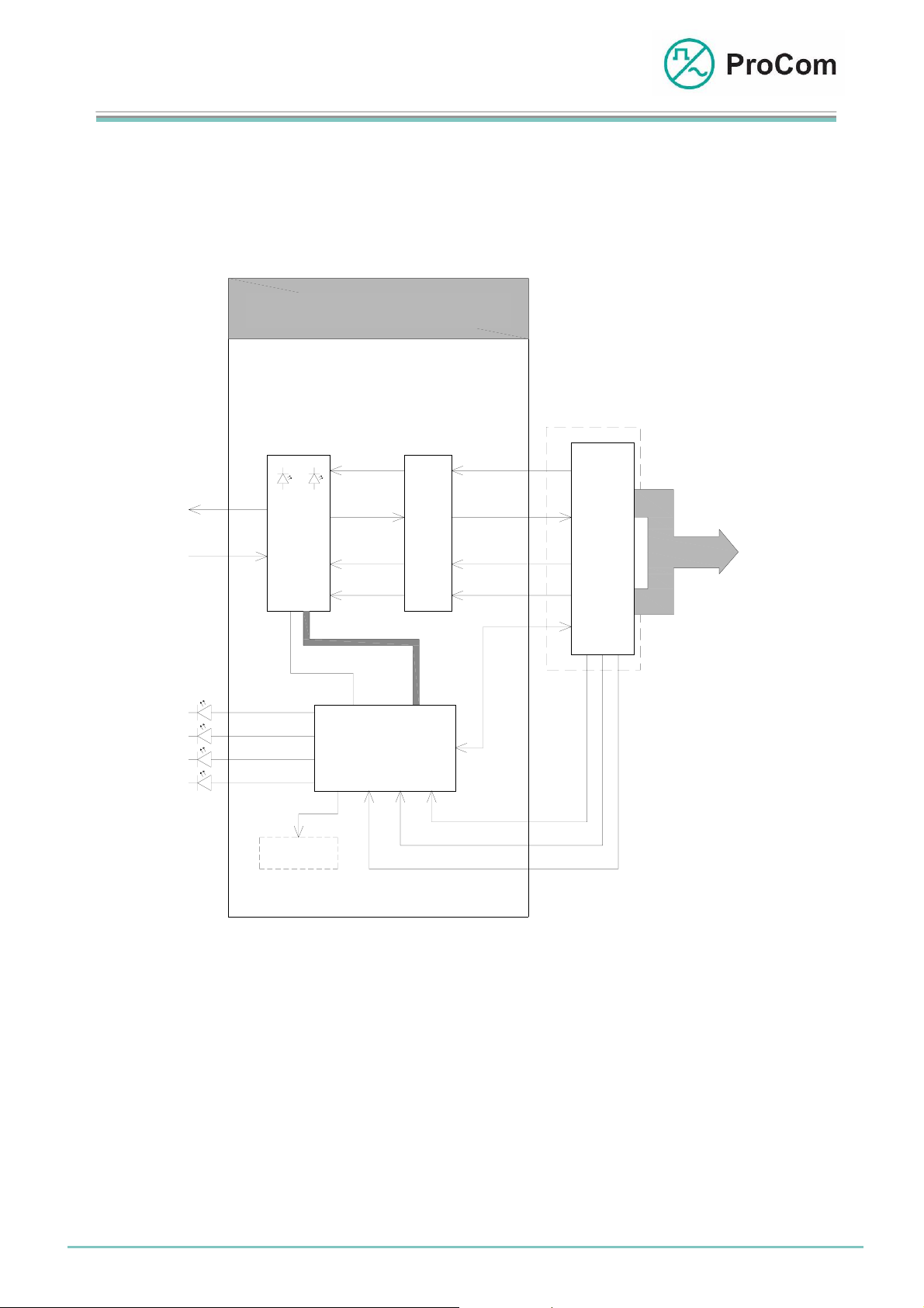
The following block diagram illustrates the way the S0 attachment for 4FTR or LCPU
functions.
S0- Aufsatz
S0-Attachment
LED1 LED2
Tx
S0
R
indication 4FTR
indication 4FTR
indication 4FTR
indication 4FTR
S0-
Modul
x
Display
Digital Upload
IOM2
Digital Download
UART
RST
µ- Prozessor
DU
DD
FRM
CLK
8k
Slip
Buffer
F
P
G
A
10MHz
Digital Input
PCM32
Digital Output
UART
RST
STI
STO
FRM
CLK
4FTR
B
u
s
C
P
U
P
C
M
BUS
lock diagram for S0 attachment
The FPGA regulates the S0 flow of data between the S0 attachment and the
BusCPU on the 4FTR or LCPU. Here the BusCPU is the interface to the DVS-21 and
the S0 attachment the interface to the outside world.
The microprocessor controls the other functions such as e.g. LEDs on the 4FTR.
The display is an aid to programme the telephone numbers for the person doing the
commissioning.
Date
20.08.2008
Page:
2/10
© 2008 ProCom, All rights and technical changes reserved
Author: HS Document-No.:
S0_DB_2870_01
Page 3
Data Sheet
S0 Attachment
S0 Attachment for 4FTR and LCPU
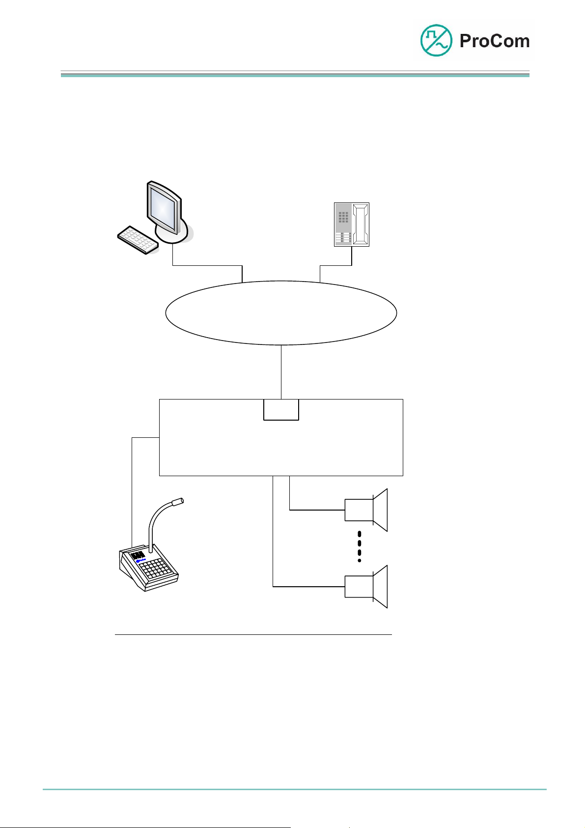
Public addressing can be carried out for remote locations with the digital switching
system DVS-21 over private and public communications networks.
Two typical application examples are shown as follows.
ISDN-capable
user work station with monitor
ISDN- telephone
Euro- ISDN
S0
DVS- 21
Loudspeaker circuit 1
Platform 1
Call station
(DTA-030)
Loudspeaker circuit n
Platform n
Example 1: Remote public address on train platforms
The S0 attachment in the DVS-21 is connected to a basis connection of the ISDN
network (Euro-ISDN: protocol E-DSS1). Public addressing can be carried out through
other devices connected to the ISDN network.
Date
20.08.2008
Page:
3/10
© 2008 ProCom, All rights and technical changes reserved
Author: HS Document-No.:
S0_DB_2870_01
Page 4

Data Sheet
S0 Attachment
S0 Attachment for 4FTR and LCPU
Work station with
monitor
Telephone
PABX
ISDN
BA
S0
DVS- 21
Loudspeaker circuit 1
Call staion
(DTA-030)
Loudspeaker circuit n
Example 2: Remote public over PABX systems
The second example is used typically in industrial applications. For this the telephone
system must have at least one ISDN basis connection as interface for the DVS-21
system. Public addressing for remote locations can be carried out here, too, through
various devices.
The basic function sequence is the same for both applications.
Date
20.08.2008
Page:
4/10
© 2008 ProCom, All rights and technical changes reserved
Author: HS Document-No.:
S0_DB_2870_01
Page 5

Data Sheet
S0 Attachment
S0 Attachment for 4FTR and LCPU
Function Description:
A call number with an appropriate priority is allocated to each loudspeaker
circuit. Up to 16 call numbers can be stored on the S0 attachment for
announcements.
An authentication is carried out by comparing the call number of the caller
with the stored call numbers.
The DVS-21 system permits allocation of 99 priorities for low frequency (LF)
connections. Public address through S0 can be given priority compared to
other connections in the system.
Up to 31 call numbers and a service number can be stored for outgoing calls.
A service number is called automatically in the case of disruptions and a
stored text message (up to 8 seconds) or a disruption audio signal is sent.
Acknowledge signals indicate whether the system is ready for an
announcement or if an announcement was successful.
Announcements are brought to a close either when the caller hangs up,
through a pause in speaking, a cancellation of priority or a timeout.
Date
20.08.2008
Page:
5/10
© 2008 ProCom, All rights and technical changes reserved
Author: HS Document-No.:
S0_DB_2870_01
Page 6

Data Sheet
p
y
V
p
r
K
y
V
V
y
V
V
S0 Attachment
S0 Attachment for 4FTR and LCPU
The following flow chart illustrates how an S0 public address system works:
Call S0
Pub. Addr.
Authority Check
Authorized?
yes
Check System
Status
Busy?
yes
Priority Check
Higher
Priority?
yes
Public Address with
Lower Priority is
Interru
Pos. ACK and
Public Add
Check End Criteria
Timeout?
no
oice Pause?
no
ReducePrio. ?
no
Hung Up?
LK Circuit Check
Loudspeaker
Circuit OK?
yes
Date
20.08.2008
Page:
no
ted
ess
yes
yes
yes
yes
no
6/10
© 2008 ProCom, All rights and technical changes reserved
Depending on
S
stem
Ignore Caller?
no
Depending on
S
stem
no
Neg. AC
no
Pos. ACK
Author: HS Document-No.:
oice Output
Configured?
yes
oice Output
Depending on
stem
S
oice Output
Configured?
yes
oice Output
System Hangs
u
S0_DB_2870_01
yes
Page 7

Data Sheet
g
V
A
p
V
p (
)
A
p
(
)
S0 Attachment
S0 Attachment for 4FTR and LCPU
In the second flow chart the process of calling a service number is illustrated:
DVS-21 Signal
Line 100
Service Number
is Called
Busy?
no
Call
Accepted?
yes
Depending on
uration
Confi
oice Output
Configured?
yes
oice Output
System Hangs
u
Return Call Expected
According to
Schedule
Return Call
Received?
yes
System Hangs
End
U
After Preset Time
yes
no
no
no
udio Signal
Configured?
yes
udio Signal
System Hangs
U
Date
20.08.2008
Page:
7/10
© 2008 ProCom, All rights and technical changes reserved
Author: HS Document-No.:
S0_DB_2870_01
Page 8

Data Sheet
S0 Attachment
S0 Attachment for 4FTR and LCPU
Arrangement of a DVS-21 for S0 public address:
The DVS-21 public address system has a modular structure.
A system can consist of one or multiple 19” attachment racks in which all
attachments for control and switching as well as the power supply
attachment (input 48/60 Volt) are placed.
A DVS-21 remote public address system includes the following attachments:
• DC/DC converter Type: SV01
• Processor Type: CPU1
• Digital speech memory Type: DSS1
• Four carriers Type: 4FTR with S0 attachment
• Universal interfaces Type: 4IOS
• Amplifier Type: V100
Error message input/output, LF monitoring of the loudspeaker circuits (LC)
and LC distribution are realized through 4IOS.
The use of multiple V100s and V100s with disaster function is possible.
Date
Minimal configuration of a DVS-21 for S0 public address:
For stepped offset public address for other locations, additional systems can
be networked through double copper wire (attachment 4NSA/4NPA) or 2
Mbit/s connection (attachment 4FTR with E1 attachment).
This kind of networking allows the announcement to be passed on in a
controlled way over S0.
20.08.2008
Page:
8/10
© 2008 ProCom, All rights and technical changes reserved
Author: HS Document-No.:
S0_DB_2870_01
Page 9

Data Sheet
S0 Attachment
S0 Attachment for 4FTR and LCPU
The Front Plate Symbols and their Meaning:
The System Blinker
Addressing from processor taking place
I/O Input/Output
BUS output works as push-push operation with the system blinker
BUS input works as push-pull operation with the system blinker
On Channel Active
Live public address (LF)
Al Error in Attachment
(Card related display)
Receiving: Control Data from External Interface
(Card related display)
Sending: Control Data to External Interface
(Card related display)
Technical Data:
Operating Voltage: +/-5 V (control)
Operational Current (+5V): xx mA
Operational Current (-5V): xx mA
Interface: Euro ISDN
Protocol: E-DSS1 (based on ITU-T I.411)
Date
20.08.2008
Page:
9/10
© 2008 ProCom, All rights and technical changes reserved
Author: HS Document-No.:
S0_DB_2870_01
Page 10

Data Sheet
S0 Attachment
S0 Attachment for 4FTR and LCPU
Temperature Range: 0 °C to 45 °C
Weight (4FTR): 155 g
Weight (S0 Attachment): xx g per attachment
Installation Height (4FTR): 3HE
Installation Width (4FTR): 6TE
Dimensions (S0 Attachment): 34 mm x 80 mm (height x width)
Number of Modules: 4FTR: Æ up to 4 attachments
LCPU: Æ 1 attachments
Date
20.08.2008
Page:
10/10
© 2008 ProCom, All rights and technical changes reserved
Author: HS Document-No.:
S0_DB_2870_01
 Loading...