

Page 1

rmv
electronics
RS232/RS485 Converter User’s Guide
DISCLAIMER: RMV ELECTRONICS INC. does not assume any liability arising from the application and/or use of
the product/s described herein, nor does it convey any license. RMV ELECTRONICS INC. products are not authorized
for use as components in medical, life support or military devices without written permission from RMV ELECTRONICS
INC.
The material enclosed in this package may not be copied, reproduced or imitated in any way, shape or form without the
written consent of RMV ELECTRONICS INC. This limitation also applies to the firmware that the Integrated Circuits in
this package might contain.
WARRANTY: RMV ELECTRONICS INC. will replace, free of charge, faulty components in this package with the
exception of the Integrated Circuits it might contain, for a period of 6 months after the date of purchase.
Chapter 1 INTRODUCTION
The RS232/RS485 converter allows the user to interface any device that uses an RS232 serial link to an
RS485 link. The RS485 link was conceived for long distance data acquisition and control applications.
The original specifications (which have been surpassed by the present hardware), supports a network of
up to 32 stations on the same lines, at speeds up to 115,200 baud to distances of 4,000 feet (1,200 meters).
The link is balanced so that any electrical noise getting into one of the lines also gets into the other line
thus allowing the receiver to cancel both noise signals.
RS485 links are much used in industrial process control where reliability is important. Also, the ability to
communicate over a long distance at a high speed is important for industrial plants where the stations
might be spread over a large area.
It is very common to have a PC in charge of controlling a given process. PC's in general have an RS232
serial port (COM port) and therefore there are two solutions to linking the computer to an RS485
network. One, is to install an RS485 interface in an expansion slot of the computer, and the other is to
convert the RS232 level signal coming out the computer serial port to an RS485 signal. This is what the
RS232/RS485 converter does. The converters are designed to work with the RMV Electronics RS485 line
of Data Acquisition and Control Boards. The RS485 Boards are specifically built for process control but
they can also be used back to back thus providing an RS232/RS485/RS232 link. This way, two computers
or devices using a standard RS232 serial port can communicate with each other at a maximum of 115,200
Bauds over a distance of up to 4000 feet, something impossible to achieve using an RS232 link. One
interesting application for using two RS232/RS485 converters back to back is when a computer needs to
be connected to an I/O-232 board at a distance longer than usual. This provides very good performance
while maintaining the simplicity of the RMV I/O-232 line of Data Acquisition and Control Boards.
1
Page 2
Chapter 2 GETTING STARTED
JUMPERS
POWER REQUIREMENTS:
The RS232/RS485 Converter can be powered using any voltage less than 32 volts. The converter
consumes 75 mA. From the converter, a 6 wire line carries the data to and from the remote stations. Two
wires send data, two wires receive data, one additional line is connected to the computer's ground and one
wire is connected to the power supply input (before the converter's voltage regulator). This way,
unregulated power can be carried to the remote stations.
The RS232/RS485 converter is NOT optoisolated. Optoisolation must be provided independently in each
station along the network as is the case with the RS485 Data Acquisition and Control line of boards.
LINE CONNECTIONS AND TERMINATION:
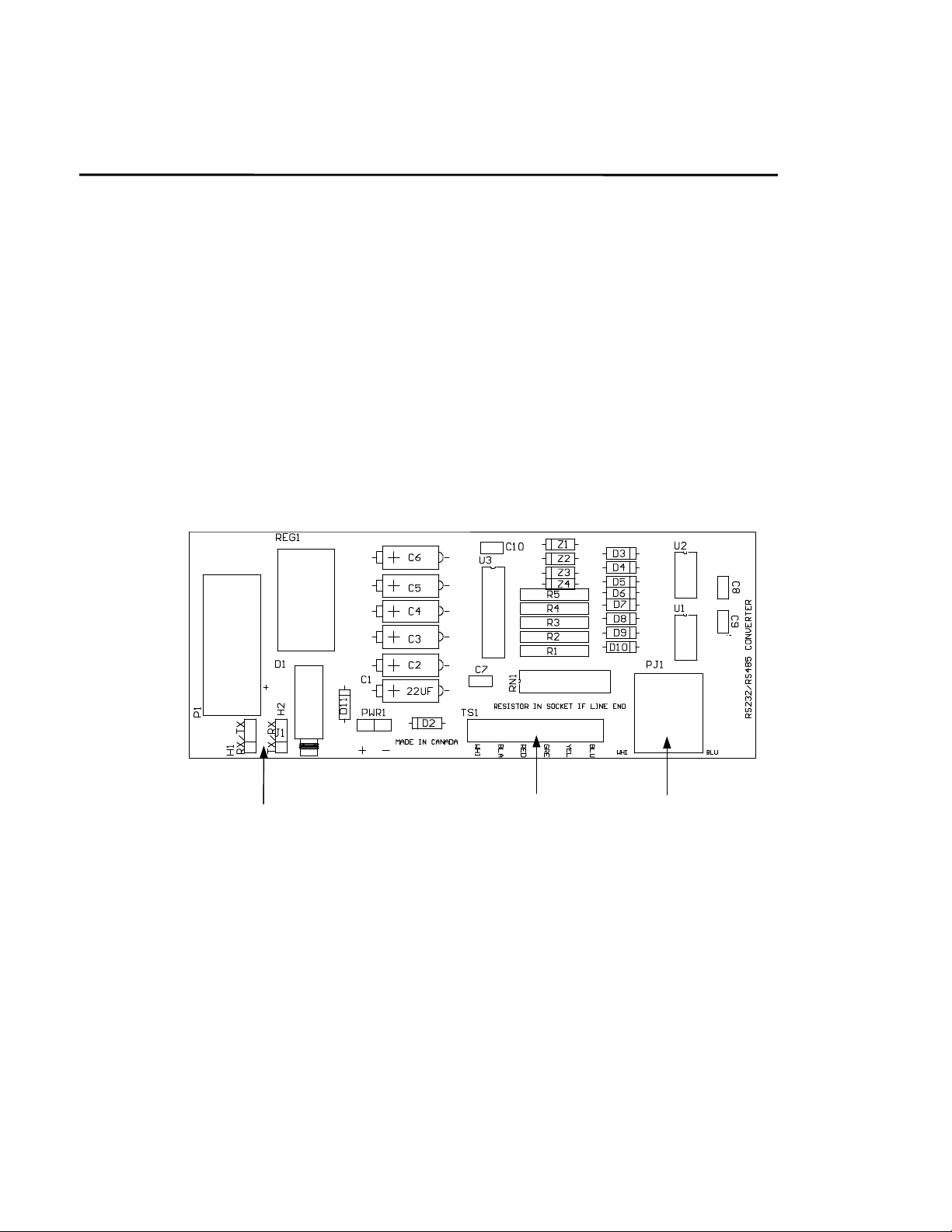
The 6 wire link can be brought to the on-board telephone jack (RJ11) or to the 6 position terminal strip
thus allowing the use of any type of wire for the link.
TERMINAL STRIP
RJ11
Figure 1.
When connecting to the terminal strip, data is transmitted via the terminal strip lines marked YELLOW
and BLUE in Figure 1, whereas data is received via the BLACK and WHITE lines. The line must be
terminated by a resistor network which is placed across the 2 pairs of data wires. For this, a non-bussed,
14 or 16 pin resistor network is required. (The pin-out is not important since the only 2 resistors used are
the ones at the centre of the network). Using a resistor network allows the placement of different
resistance values. 120 Ohms is recommended, but in fact, the resistance should match the impedance of
the data transmission line.
IMPORTANT: For optimal operation, a data network requires termination on both ends of the link. This
means that intermediate stations need NOT be terminated with resistors (if you are using the RMV RS485
2
Page 3

line of Data Acquisition and Control Boards, you should remove the resistor networks on all the RS485
stations but the last one).
The data lines are protected by 4 diodes and 2 Zeners each, which prevent voltages over 6 Volts from
reaching the drivers.
CONNECTION TO THE COMPUTER:
The RS232/RS485 Converter has a 9 pin DB9 connector of which only 3 lines are used: TX, RX and
Ground. The Converter is connected to the computer with a serial cable through the DB9 connector to the
target computer’s serial port. Commercial serial cables can have either ‘straight’ data lines or ‘crossed’
(null modern) data lines.
In order to accommodate both types of cables, jumpers H1 and H2 are provided to allow for either a
‘straight’ or a ‘crossed’ connection to the TX and RX lines. If a ‘straight’ cable is used, jumper H1 is set
on RX and H2 on TX. If a ‘crossed’ cable is used, jumper H1 must be set on TX and H2 is set on RX. No
RTS or other control lines are used since the link is fully duplex.
Figure 2.
3
Page 4

Chapter 3 TROUBLESHOOTING
A very easy way to troubleshoot these boards is to use a jumper wire to join together the BLUE and
WHITE lines and another jumper wire to connect the BLACK and YELLOW lines on the 6 position
terminal strip. (Make sure you have no other devices connected on the RS485 lines and disable the local
echo function on the terminal emulation program.) This results in a closed loop and therefore whatever
you type on a computer terminal emulation program (such as Procomm, Hyper Terminal or Windows
Terminal) should be echoed back to the screen if the board is working properly. If the echo-on feature in
the program is selected, then you would get each character twice.
The Baud rate as well as the number of bits or the stop bit are all irrelevant. Should it not work properly,
the first thing to check is that the board is powered properly, and secondly, to move the jumpers to the
appropriate positions on both H1 and H2. (Note: The jumpers should always be both on the same relative
positions. That is, closing either pins 1-2 with both H1 and H2 or 2-3 with both jumpers.)
4
 Loading...