

Page 1
IMPORTANT: Read and understand this manual before
assembling, starting or servicing heater. Improper use
of heater can cause serious injury. Keep this manual for
future reference.
Never use heater in living or sleeping areas.
Heater is suitable for outdoor use and for use on com-
bustible oors.
PORTABLE FORCED AIR HEATERS
KEROSENE/DIESEL HEATER WITH BUILT-IN THERMOSTAT
OWNER’S MANUAL
PCK110VT - ADJUSTABLE 80-110,000 BTU/HR
PCK160VT - ADJUSTABLE 110-160,000 BTU/HR
PCK175VT - ADJUSTABLE 125-175,000 BTU/HR
PCK220VT - ADJUSTABLE 160-220,000 BTU/HR
Questions, problems, missing parts? Before returning to your retailer, call
our customer service department at 1-866-573-0674, 7:30 am - 4:15 pm CST,
Monday through Friday or email customerservice@usaprocom.com
Page 2
www.usaprocom.com
160108-01B2
2. Fueling
a) Personnel involved with fueling shall be
qualied and thoroughly familiar with
the manufacturer's instructions and
applicable regulations regarding the
safe fueling of heating units.
b) Only the type of fuel specied on the
heater's data plate shall be used.
c) All ame shall be extinguished and the
heater allowed to cool, prior to fueling.
d) During fueling, all fuel lines and fuel-
line connections shall be inspected for
leaks. Any leaks shall be repaired prior
to returning the heater to service.
e) At no time shall more than one day's
supply of heater fuel be stored inside
a building in the vicinity of the heater.
Bulk fuel storage shall be outside the
structure.
f) All fuel storage shall be located a mini-
mum of 25 feet (762 cm) from heaters,
torches, welding equipment and similar
sources of ignition (exception: fuel reservoir integral with heater unit or any
authorized auxiliary tank connected to
heater unit).
g) Whenever possible, fuel storage shall
be conned to areas where oor penetrations do not permit fuel to drip onto
or be ignited by a re at lower elevation.
h) Fuel storage shall be in accordance
with the authority having jurisdiction.
3. Use only the electrical voltage and frequency specied on model plate.
4. Heater is suitable for outdoor use.
5. Heater must be grounded. Use only a
properly grounded three-wire extension
cord. Plug into grounded outlet only.
6. Use only in areas free of ammable vapors or high dust content.
WARNING: This product
contains and/or generates
chemicals known to the State
of California to cause cancer or
birth defects or other reproductive harm.
IMPORTANT: Read this owner’s
manual carefully and completely
before trying to assemble,
operate or service this heater.
Improper use of this heater can
cause serious injury or death
from burns, fire, explosion,
electrical shock and carbon
monoxide poisoning.
DANGER: Carbon monoxide
poisoning may lead to death!
Carbon Monoxide Poisoning: Early signs of
carbon monoxide poisoning resemble the u,
with headaches, dizziness and/or nausea. If
you have these signs, the heater may not be
working properly. Get fresh air at once! Have
heater serviced. Some people are more affected by carbon monoxide than others. These
include pregnant women, persons with heart
or lung disease or anemia, those under the
inuence of alcohol and those at high altitudes.
Make certain you read and understand all
warnings. Keep this manual for reference. It
is your guide to safe and proper operation of
this heater.
1. Use only kerosene, #1/#2 diesel/fuel oil,
JET A or JP-8 fuels to avoid risk of re or
explosion. Never use gasoline, oil from
crank cases, naphtha, paint thinners,
alcohol or other highly ammable fuels.
SAFETY
TABLE OF CONTENTS
Safety ........................................................ 2
Unpacking.................................................. 3
Assembly ................................................... 3
Product Identication and Label Locations 5
Specications ............................................ 6
Fuels .......................................................... 6
Ventilation .................................................. 6
Operation ................................................... 7
Operation with Portable Generator ............ 8
Storing, Transporting or Shipping .............. 8
Preventative Maintenance Schedule ......... 8
Troubleshooting ......................................... 9
Service Procedures ................................. 13
Wiring Diagram ........................................ 18
Technical Service..................................... 18
Accessories ............................................. 18
Parts ........................................................ 19
Replacement Parts .................................. 23
Warranty .................................................. 24
Page 3
www.usaprocom.com
3160108-01B
SAFETY
UNPACKING
7. Minimum clearance from any combustible
materials: 8 feet (244 cm) from hot air
outlet, 6 feet (183 cm) from top, and 4
feet (120 cm) from sides and inlet.
8. Locate heater on a stable and level surface while hot or operating or a re may
occur.
9. Heater is acceptable for use on ooring
such as wood (a combustible material).
10. Use only in well vented areas. Before
using heater, provide at least a 3 ft2
(2800 cm2) opening of fresh, outside air
for each 100,000 Btu/Hr (30 kw) of rating.
11. Keep children and animals away from
heater at all times.
12. Never start heater when combustion
chamber is hot or if fuel has accumulated
in combustion chamber.
13. This heater is equipped with a thermostat.
Heater may start at anytime.
14. Never leave a heater plugged in without
adult supervision if children or animals are
likely to be present.
15. Use caution when moving or storing
heater when fuel tank contains fuel. Fuel
spillage can occur.
16. Use heater only in accordance with local ordinances and codes. Canadian
residents should refer to CSA standard
B139, Installation Code for Oil Burning
Equipment for recommended installation
practice.
17. Never use gasoline, crankcase drainings,
naphtha, paint thinners, alcohol or other
highly ammable fuels.
18. Never use heater where gasoline, paint
thinner or other highly ammable vapors
are present.
19. Never use heater in living or sleeping
areas.
20. Never move, handle, refuel or service a
hot, operating or plugged-in heater.
21. Never attach duct work to front or rear of
heater.
22. Heaters used in the vicinity of tarpaulins,
canvas or similar enclosure materials shall
be located a safe distance from such materials. The recommended minimum safe
distance is 10 feet (304.8 cm). It is further
recommended that these enclosure materials be of a re retardant nature. These
enclosure materials shall be securely fastened to prevent them from igniting or from
upsetting the heater due to wind action.
23. Unplug heater when not in use.
24. Never block air inlet (rear) or air outlet
(front) of heater.
25. Warning to New York City Residents
For Use Only At Construction Sites in
accordance with applicable NYC codes.
26. Never use external fuel sources or tanks
that are not specically designed for use
with this heater.
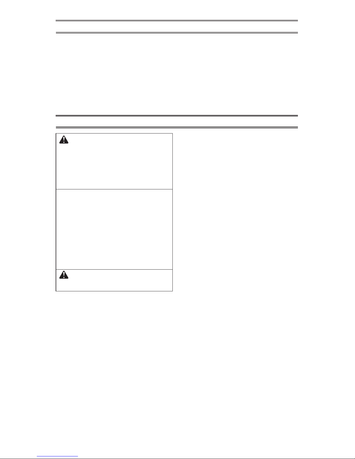
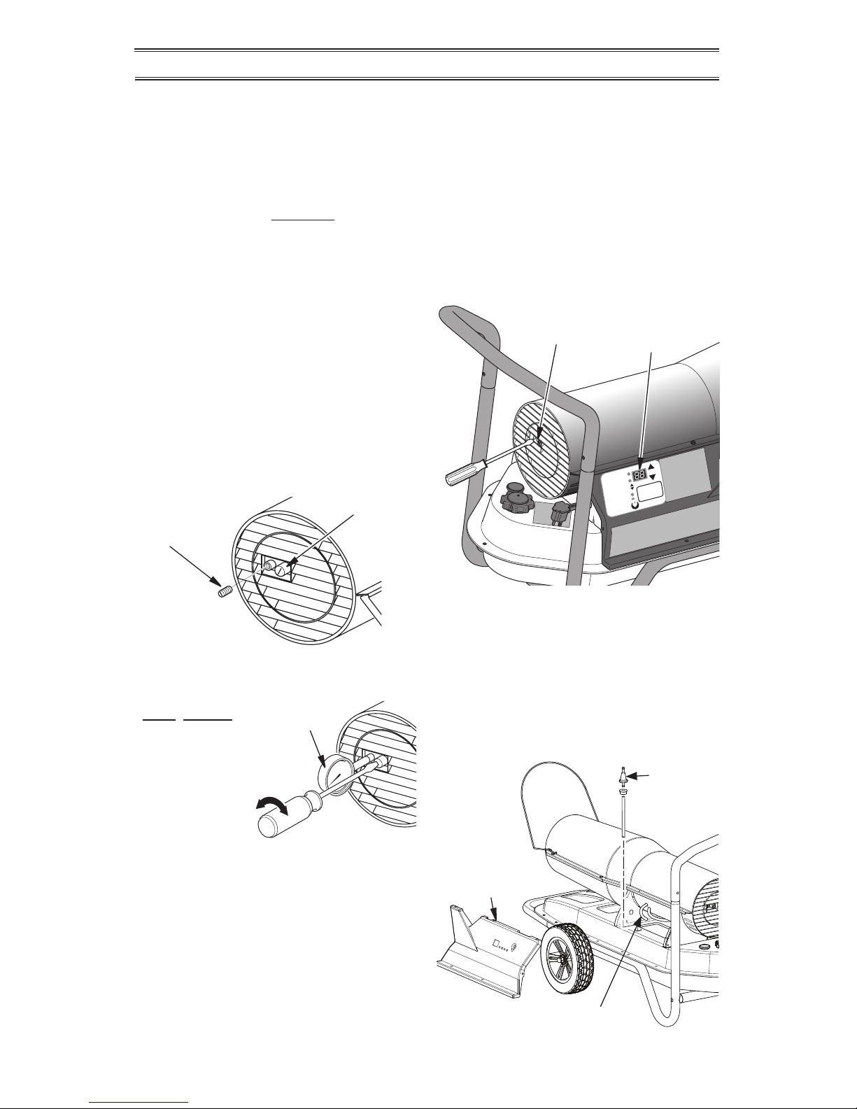
Figure 1 - Wire Guard Moved to Locked
Position
1. Remove all packing items applied to
heater for shipment.
2. Remove all items from carton.
3. Check items for any shipping damage. If
heater is damaged call ProCom Heating,
Inc. at 1-866-573-0674 for replacement
parts before returning to dealer.
ASSEMBLY
WIRE GUARD
All Models
Grasp wire guard from top of shell and pull
towards front of heater until it locks into place
in slots on both sides of upper shell.
Page 4
www.usaprocom.com
160108-01B4
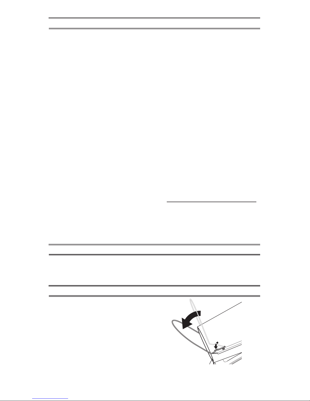
WHEEL ASSEMBLY
Models 160, 175 and 220
1. Slide Axle (A) through holes in wheel support frame.
2. Slide Wheel Spacer (B), then wheel (D) (concave side facing outward) onto axle.
3. Attach Acorn Nut (C) nger tight to end of axle.
4. Repeat steps 2 and 3 for opposite side, then tighten nuts with adjustable wrench.
Axle (A)
Acorn Nut (C)
Wheel (D)
Spacer (B)
Figure 2 - Wheel Assembly, 160, 175 and 220 Models
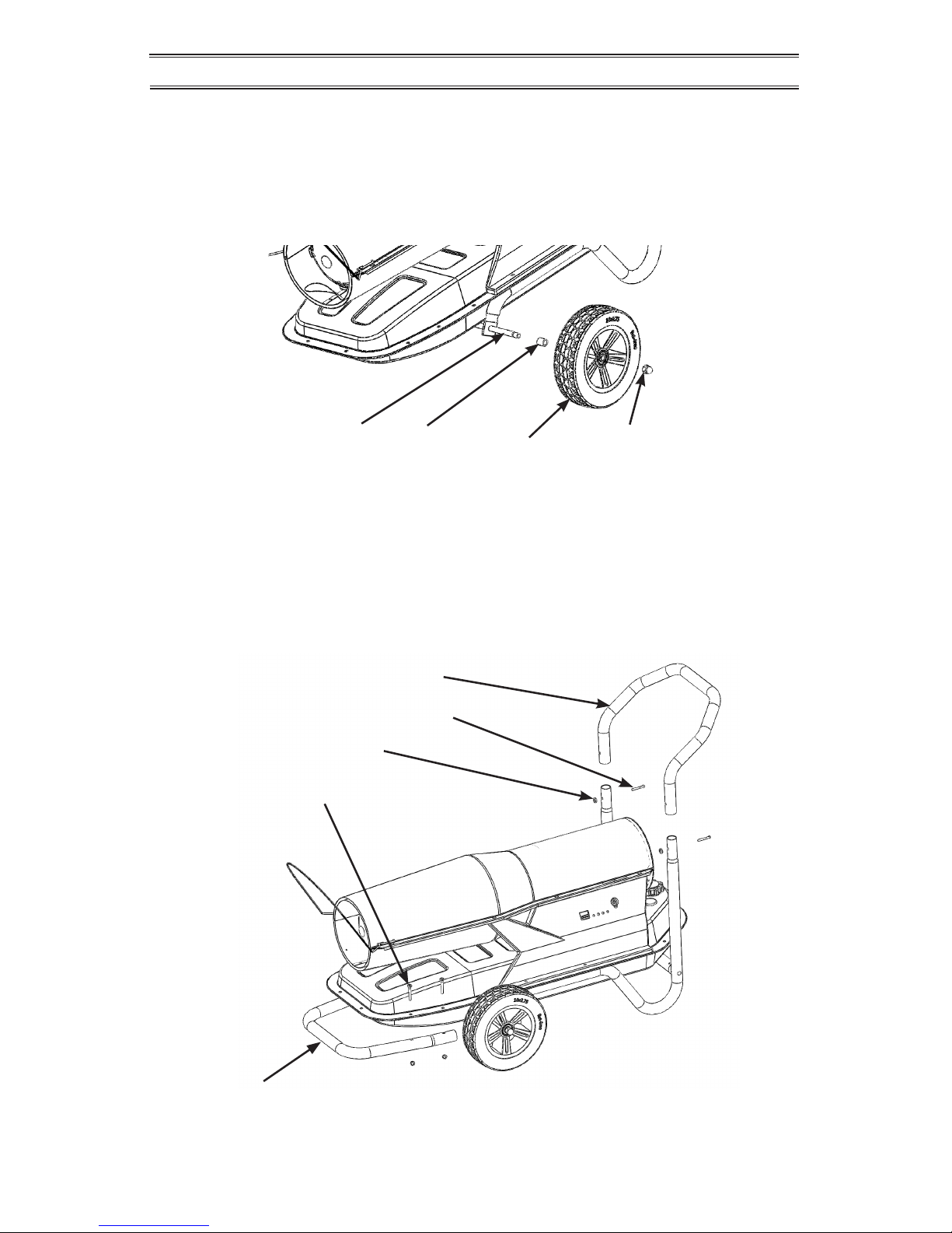
HANDLE ASSEMBLY
Models 160, 175 and 220
1. Slide rear handle (E) onto Wheel Support Frame. Insert Screws (G) from rear and attach
lock nuts (F).
2. Place Front Handle (I) under ange of fuel tank and insert 4 screws (J) from top of ange
through holes in ange into holes in handle. Attach Lock Nuts (H) and tighten.
Rear Handle (E)
Screw, 10-24 x 1.5 (G)
Lock Nut 10-24 (F)
Screw 1/4-20 x 1.75" (J)
Front Handle (I)
Figure 3 - Handle Assembly, 160, 175 and 220 Models
ASSEMBLY
Page 5
www.usaprocom.com
5160108-01B
PRODUCT IDENTIFICATION AND LABEL LOCATIONS
Fueling Label
Part No. 160168-01
Control Label
Part No. 160167-02
CSA Label (Rating Plate)
Part No. 160111-04, 110 model
Part No. 160112-02, 160 model
Part No. 160112-03, 175 model
Part No. 160112-05, 220 model
Operating Label
Part No. 160173-01
Operating Codes Label
Part No. 160174-01
Maintenance Label
Part No. 160175-01
Caution Label
Part No. 160172-01
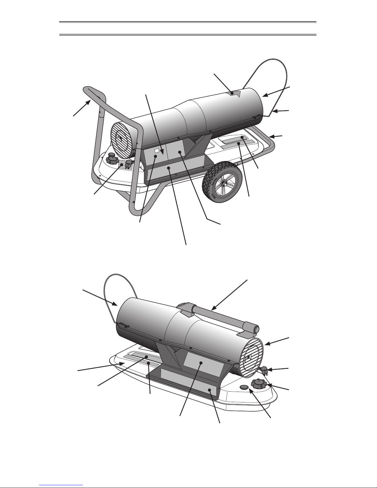
Figure 4 - Product Identication & Label Locations
English Warnings
Label 160110-01
French Warnings
Label 160110-02
Spanish Warnings
Label 160110-03
NY, MA and CA
Information Label
Part No. 160169-01
All Models
Right Side
(220 Model Shown)
All Models
Left Side
(110 Model Shown)
Front
Handle
(160, 175 &
220 models)
Hot Air
Outlet
Control
Panel
Rear Handle
(160, 175 &
220 models)
Wire
Guard
Top Handle
(110 model)
Fuel
Tank
Cold Air
Inlet
Power
Cord
Fuel Cap
Fuel
Gauge
Hot Air
Outlet
Page 6
www.usaprocom.com
160108-01B6
SPECIFICATIONS
VENTILATION
Example: A 220,000 Btu/Hr (64.5 kw) heater
requires one of the following:
• a two-car garage door [16 feet (4.88 meter)
opening] raised 5" (12.7 cm)
• a single-car garage door [9 feet (2.74 meter) opening] raised 9" (22.9 cm)
• two, 30" (76.2 cm) windows raised 16"
(40.6 cm)
FUELS
• noticeable odor
• additional fuel lter maintenance
* Use of #2 diesel/fuel oil in extreme cold
temperatures may require nontoxic anti-icer
additives.
Do not use fuels heavier than No. 2 grade
or heavy oils such as oil drained from crankcases. These heavy oils will not ignite properly
and will contaminate the heater.
IMPORTANT: Use a KEROSENE ONLY (blue)
or DIESEL ONLY (yellow) storage container.
Be sure storage container is clean. Foreign
matter such as rust, dirt or water will cause the
ignition control assembly to shut down heater.
Foreign matter may also require heater's fuel
system to be frequently cleaned.
PCK110VT PCK160VT PCK175VT PCK220VT
Output Rating 80K-110K 110K-160K 125K-175K 160K-220K
Fuel (all models) Use only kerosene, #1/#2 diesel*/fuel oil, JET A or JP-8 fuels
Fuel Tank Capacity 5.5 gal/20.8 L 10 gal/37.9 L 10 gal/37.9 L 14 gal/53 L
Fuel Consumption (per hr) 0.82 gal/3.1 L 1.19 gal/4.5 L 1.3 gal/4.9 L 1.64 gal/6.2 L
Pump Pressure 6.9 PSI (hot) 6.7 PSI (hot) 6.8 PSI (hot) 8.4 PSI (hot)
Electric Requirements 120 V/60 HZ 120 V/60 HZ 120 V/60 HZ 120 V/60 HZ
Amperage (Normal Run) 2.9 3.2 3.4 4.6
Typical Motor Speed 3400 RPM 3400 RPM 3400 RPM 3400 RPM
Motor 1/4 hp 1/4 hp 1/4 hp 1/4 hp
Shipping Weight 42 lbs/19 kg 71 lbs/32.2 kg 71 lbs/32.2 kg 77 lbs/35 kg
Heater Weight without
Fuel (approx)
36 lbs/16.3 kg
60.5 lbs/27.4 kg 60.5 lbs/27.4 kg 66 lbs/29.9 kg
WARNING: Use only kerosene, #1/#2 diesel/fuel oil, JET
A or JP-8 fuels to avoid risk
of re or explosion. Never use
gasoline, oil drained from crankcases, naphtha, paint thinners,
alcohol or other highly ammable fuels.
Use only kerosene, #1/#2 diesel*/fuel oil,
JET A, JP-8 fuels. Heavier fuels such as No.
2 fuel oil, No. 2 diesel fuel may also be used
but will result in:
WARNING: Provide a fresh air
opening of at least three square
feet (2,800 square cm) for each
100,000 BTU/HR rating. Provide
extra fresh air if more heaters
are being used. The minimum
ventilation requirements must
be followed to avoid risks associated with carbon monoxide
poisoning. Make certain these
requirements are met prior to
operating heater.
Page 7
www.usaprocom.com
7160108-01B
ASSEMBLED IN THE USA BY:
ASSEMBLE AUX ETATS-UNIS PAR:
ENSAMBLADA EN LOS EE.UU.POR:
PROCOM HEATING, INC.
2800 GRIFFIN DRIVE
BOWLING GREEN, KY 42101
`
THERMOSTAT MODE
MODE/RESET
PUMP PRESSURE
STAND BY
ON/STOP
TEMPERATURE
MANUAL MODE
MODE MANUEL/MODO MANUAL
MODE/REINITIALISATION
`
MARCHE/ARRET
^
MODE THERMOSTAT
THERMOSTATO MODO
MODO/RESTABLECER
ENCENDER/APAGAR
TEMPERATURA
160167-02
PRESSION DE LA POMPE
PRESION DE BOMBA
`
ADJUST
AJUSTE
IMPORTANT: Review and understand the warnings in the Safety
section, page 2. They are needed
to safely operate this heater.
Follow all local ordinances and
codes when using this heater.
TO START HEATER
1. Follow all ventilation and safety information.
2. Locate heater to provide maximum circulation of the heated air. Follow all location
requirements noted in Safety, pages
2 and 3.
3. Fill fuel tank with fuel and attach fuel cap.
Use only kerosene, #1/#2 diesel/fuel oil,
JET A or JP-8 fuels to avoid risk of re or
explosion. Never use gasoline, oil drained
from crankcases, naphtha, paint thinners,
alcohol or other ammable fuels.
4. Plug heater’s power cord into approved,
grounded, three-wire extension cord.
Extension cord must be at least 6 feet
(1.8 m) long.
Extension Cord Size Requirement
• 6 to 10 feet (1.8 to 3 m) long, use 18
AWG (0.75 mm2) rated cord
• 11 to 100 feet (3.3 to 30.5 m) long, use
16 AWG (1.0 mm2) rated cord
• 101 to 200 feet (30.8 to 61 m) long, use
14 AWG (1.5 mm2) rated cord
5. Plug extension cord into standard 120
volt/60 hertz, 3-prong grounded outlet.
6. Push ON/STOP button to ON. An alarm will
sound and the display will start countdown
to ignition. The heater will start and pump
pressure will be displayed for 6 seconds.
7. Push MODE/RESET button to select
desired operating mode.
Note: When operating in Thermostat
Mode, press the MODE/RESET button
once to change to Manual Mode. When
operating in Manual Mode, Press the
MODE/RESET button twice within 5 seconds to change to Thermostat Mode.
Manual Mode LED On: Adjust output to
desired setting. Press to raise the BTU
output. Press to lower the BTU output.
Note: After startup, heater BTU output can
be immediately adjusted, but adjustments
will not take effect for 2 minutes. This allows the heater to stabilize.
Thermostat Mode LED On: Adjust ther-
mostat by pressing to change set point
higher. Press to change set point lower.
If thermostat set temperature is higher
than the surrounding air temperature by
3° F, the heater will ignite. If the thermostat
set temperature is lower than surrounding
air temperature, the heater will not ignite.
Heater output will adjust automatically to
maintain set temperature.
WARNING: This heater is
equipped with a thermostat.
Heater may start at any time.
TO STOP HEATER
1. Push ON/STOP button to stop heater.
2. Unplug heater when not in use.
TO RESET HEATER
1. Wait two minutes before restarting.
2. Push MODE/RESET button to restart
heater.
OPERATION
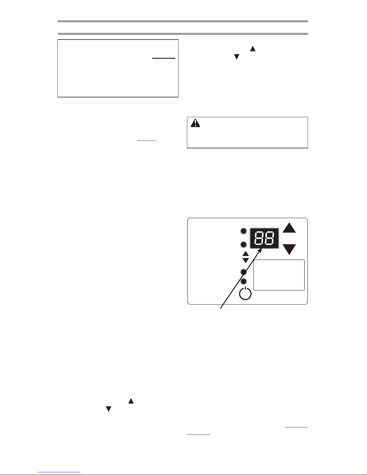
LED display will show surrounding temperature
unless up and down arrow keys are pressed.
After pressing these keys, display shows set
point temperature for ve seconds and then will
change back to display surrounding temperature.
Exposure to direct sunlight or extreme cold may
affect temperature reading and/or thermostat
operation.
This thermostat will store the last set point
even if power is removed. Unit will maintain
this set point until a new set point is entered.
Figure 5 - Controls Display
FAULT CODES
This heater will display fault codes whenever
there is a control shutdown. See Trouble-
shooting, pages 9 - 12, before attempting to
rectify any problems with your heater.
Page 8
www.usaprocom.com
160108-01B8
Ground Wire (#10 AWG Stranded-Copper)
Copper
or Brass
Grounding
Point
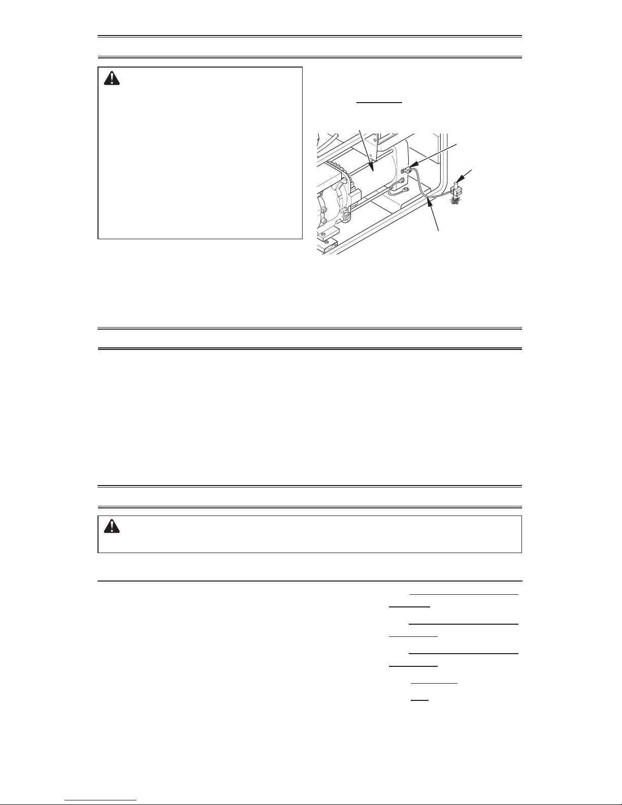
Figure 6 - Typical Generator Grounding
Method (Generator construction may
vary from that shown)
PREVENTATIVE MAINTENANCE SCHEDULE
WARNING: Never service heater while it is plugged in, operating
or hot. Severe burns and electrical shock can occur.
OPERATION WITH PORTABLE GENERATOR
Alternator
Ground Lug
WARNING: Before operating
heater or any appliance from a
portable generator, verify that
generator has been properly connected to earth ground. Improper
grounding or failure to ground
generator can result in electrocution if a ground fault occurs.
Refer to owner’s manual supplied
by generator manufacturer for
proper grounding procedures.
Operating voltage range of heater is 95 to 135
Volts. Prior to plugging heater into generator
output voltage should be veried (if generator
is equipped with automatic idle feature, output
voltage should be measured with generator
running at full speed). If voltage does not
STORING, TRANSPORTING OR SHIPPING
3. Properly dispose of old and dirty fuel.
Check with local automotive service stations that recycle oil.
4. If storing, store heater in dry place. Make
sure storage place is free of dust and
corrosive fumes.
IMPORTANT: Do not store kerosene over
summer months for use during next heating
season. Using old fuel could damage heater.
measure in this range heater should not be
plugged into generator.
Refer to Operation, page 7, for starting, stop-
ping and resetting heater procedures.
Note: If shipping, transport companies require
fuel tanks to be empty.
1. Remove excess fuel from tank using a siphon pump. Drain remaining fuel through
ller neck by tipping heater to the rear.
2. If any debris is noted in old fuel, add 1 or 2
quarts of clean kerosene to tank, stir and
drain again. This will prevent excess debris
from clogging lters during future use.
Item How Often How To
Fuel tank Clean every season or as needed. See Storing, Transporting, or
Shipping, above.
Air output and
lint lters
Replace every 500 hours of operation or
once a year.
See Air Output, Air Intake and
Lint Filters, page 13.
Air intake lter Wash and dry with soap and water every 500
hours of operation or as needed.
See Air Output, Air Intake and
Lint Filters, page 13.
Fuel lter Clean twice a heating season or as needed. See Fuel Filter, page 14.
Fan blades Clean every season or as needed. See Fan, page 13.
Motor Not required/permanently lubricated.
Page 9

www.usaprocom.com
9160108-01B
TROUBLESHOOTING
WARNING: Never service heater while it is plugged in, operating
or hot. Severe burns and electrical shock can occur.
WARNING: High voltage! Unplug heater before servicing.
DISPLAY POSSIBLE CAUSE REMEDY
Display shows
C1,C2,C3,C4,C5,C6,
C7,C8 or C9.
1. Control remembers codes
from prior operation.
1. Press MODE/RESET button
to clear Code and restart
heater.
Display is off. 1. No power to heater (All LED’s
are off).
2. Bad electrical connection
between control and power
cord.
1. Check power cord connec-
tions.
2. Unplug heater. Check all
electrical connections (see
Wiring Diagram, page 18).
Display shows room tem-
perature.
1. Thermostat setting is too low. 1. Adjust thermostat to a higher
setting by pressing button or change to MANUAL MODE by pressing the
MODE/RESET button.
Display shows C1 High
Voltage.
1. Supply voltage is above 135
volts. Generator out of regulation.
1. Confirm supply voltage is
below 135 volts.
Display shows C2 Low
Voltage.
1. Supply voltage is below 95
volts. Poor supply circuit or
extension cord too long or
inadequate gauge.
1. Confirm supply voltage is
above 95 volts. See extension cord requirements on
page 7.
Display shows C8 Te m perature over 100°F.
1. Room or ambient temperature exceeds 100°F.
1. Operate heater in a cooler
environment.
Display shows C9 Low
Pressure.
1. Bad electrical connection
between motor and power
cord.
2. Motor locked-fan obstructed.
3. Motor locked-pump obstructed.
4. Motor defective.
1. Unplug heater. Check all
electrical connections (see
Wiring Diagram, page 18).
2. Unplug heater. Clear fan
obstruction.
3. Service pump (see page 17).
4.
Unplug heater. Replace
motor.
FAULT CONDITION
Motor does not start after heater is plugged in and ON/STOP button is ON.
Page 10
www.usaprocom.com
160108-01B10
TROUBLESHOOTING
WARNING: High voltage! Unplug heater before servicing.
FAULT CONDITION
Motor starts and runs but heater does not ignite.
DISPLAY POSSIBLE CAUSE REMEDY
Display shows C9 Low
Pressure.
1. Air line or tting leaking.
2. Pump cover leaking.
Pump cover screws loose.
3. Pump cover gasket leaking.
Pump output lter clogged.
4. Pump pressure is low.
5. Pump pressure is low. Cannot adjust to specication.
1. Unplug heater. Check air
lines and ttings for leaks.
Correct all leaks.
2. Unplug heater. Check pump
cover for leaks. Tighten pump
cover screws to 10-20 in-lbs.
3. Unplug heater. Replace pump
output lter. See Pump Pres-
sure Adjustment page 14.
4. Adjust pump pressure to
specication. See Pump Pres-
sure Adjustment, page 14.
5. Service pump, see page 17.
Display shows C3 No
Ignition.
1. No fuel in fuel tank.
2. Water in fuel tank.
3. Pump pressure incorrect.
4. Dirty Fuel Filter.
5. Obstruction in Nozzle.
6. Bad electrical connection
between ignitor and control.
7. Blown control fuse.
8. Defective ignitor.
9. Defective ignition control assembly.
1. Fill Tank. See Fuels, page 6.
Restart heater.
2. Drain and flush fuel tank
with kerosene. See Storing,
Transporting or Shipping,
page 8.
3. See Pump Pressure Adjust-
ment, page 14.
4. See Fuel Filter, page 14.
5. See Nozzle Assembly, page
16.
6. Check electrical connections.
See Wiring Diagram, page 18.
7. Replace control fuse, see
page 17.
8. Replace ignitor and control
fuse, see pages 14 & 17.
9. Replace ignition control assembly.
Page 11
www.usaprocom.com
11160108-01B
TROUBLESHOOTING
WARNING: High voltage! Unplug heater before servicing.
FAULT CONDITION
Heater ignites but control assembly shuts heater off before running out
of fuel.
DISPLAY POSSIBLE CAUSE REMEDY
Display shows C4 Flame
Extinguished.
1. Not enough fuel in tank to
maintain combustion.
2. Water in fuel tank.
3. Pump pressure incorrect.
4. Dirty fuel lter.
5. Obstruction in nozzle.
6. Photocell assembly not properly installed.
7. Dirty photocell lens.
8. Defective photocell.
1. Fill tank. See Fuels, page 6.
Restart heater
2. Drain and flush fuel tank
with kerosene. See Storing,
Transporting or Shipping,
page 8.
3. See Pump Pressure Adjust-
ment, page 14.
4. See Fuel Filter, page 14.
5. See Nozzle Assembly, page
16.
6. Make sure photocell boot is
fully seated in bracket.
7. Clean photocell lens.
8. Replace photocell.
Display shows C5 Improper Flame.
1. Pump pressure too high.
2. Heater inlet or outlet is cov-
ered and unit is not getting
enough air for combustion.
3. Fan set screw is loose.
1. See Pump Pressure Adjust-
ment, page 14.
2. Unplug heater. Remove obstructions or loose material
from heater inlet or outlet.
3. Tighten fan set screw to
40-50 in-lbs. See service
procedures on page 13.
Display shows C6 Flame
Change.
1. Heater inlet suddenly blocked
by debris.
2. Water in fuel tank
3. Dirty fuel lter
4. Obstruction in nozzle
5. Fan set screw is loose
1. Unplug heater. Remove obstructions or loose material
from heater inlet.
2. Drain and flush fuel tank
with kerosene. See Storing,
Transporting or Shipping,
page 8.
3. See Fuel Filter, page 14.
4. See Nozzle Assembly, page
16.
5. Tighten fan set screw to
40-50 in-lbs. See Service
Procedures on page 13.
Page 12
www.usaprocom.com
160108-01B12
TROUBLESHOOTING
DISPLAY POSSIBLE CAUSE REMEDY
Display shows C7 Control
button stuck.
1. One or more of the control
buttons is depressed continuously (stuck).
2. Defective control assembly.
1. Unplug heater. Depress and
release each control button
several times to check operation. Every button should click
every time it is depressed.
2. Replace control assembly.
Display shows C8 Te m perature Over 100°F.
1. Room or ambient temperature exceeds 100°F.
1. Operate heater in a cooler
environment.
Display shows C9 Low
Pressure (Setting 5).
1. Air line or tting leaking.
2. Pump cover leaking. Pump
cover screws loose.
3. Pump cover gasket leaking.
Pump output lter clogged.
4. Pump pressure is low.
5. Pump pressure is low. Cannot adjust to specification.
Pump lters are dirty.
6. Pump pressure is low, pump
has excessive wear or improper adjustment.
1. Unplug heater. Check air
lines and fittings of leaks.
Correct all leaks.
2. Unplug heater. Check pump
cover for leaks. Tighten pump
cover screws to 10-20 in-lbs.
3. Unplug heater Replace pump
output lter. See Pump Rotor,
page 17.
4. Adjust pump pressure to
specication. See Pump Pres-
sure Adjustment, page 14.
5. Replace pump filters. See
page 13.
6. Adjust pump rotor gap or replace pump rotor and blades.
See page 17.
WARNING: High voltage! Unplug heater before servicing.
FAULT CONDITION
(Continued) Heater ignites but control assembly shuts heater off before
running out of fuel.
Page 13
www.usaprocom.com
13160108-01B
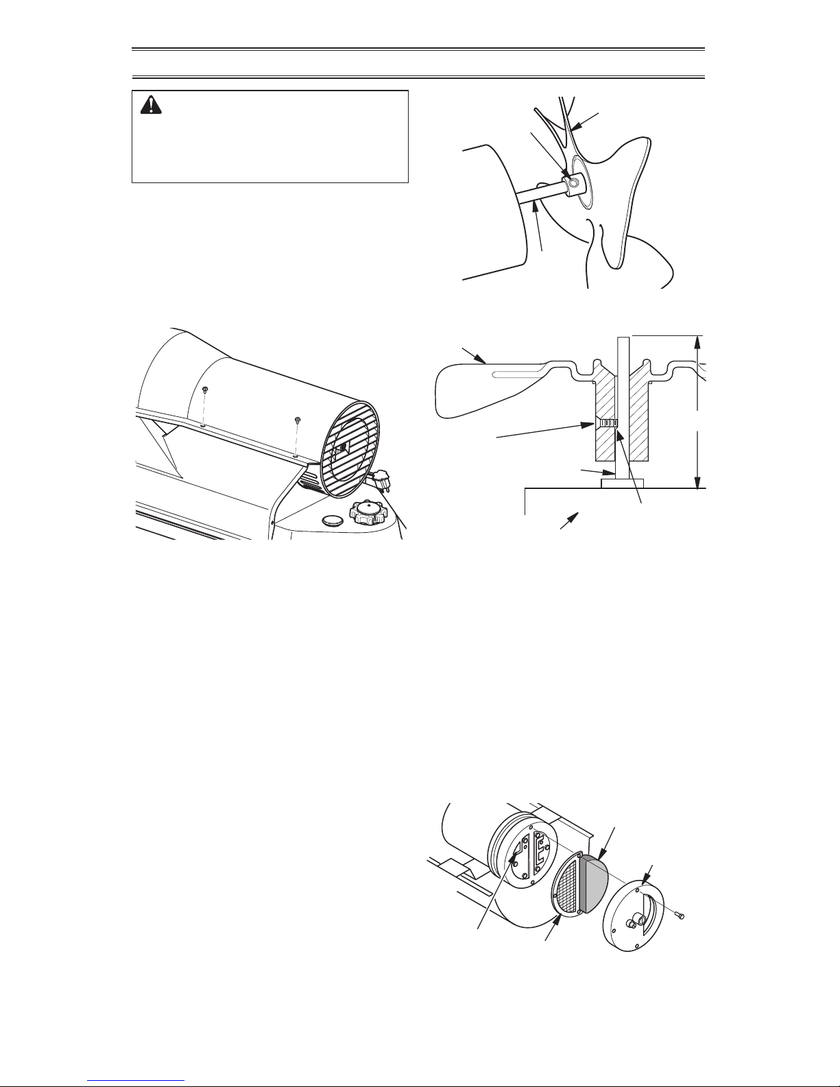
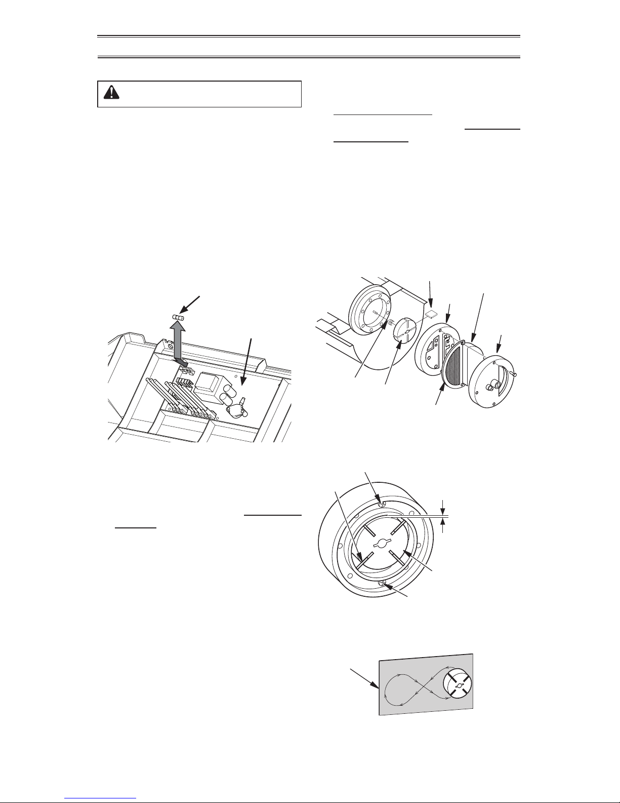
Figure 7 - Upper Shell Removal
Motor
Shaft
Setscrew
Figure 8 - Fan, Motor Shaft, and
Setscrew Location
Motor
Shaft
Back of Flat on
Motor Shaft
1.82"
Motor
Shaft
Length
Fan
Setscrew
Touching
Back of Flat
on Motor
Shaft
Figure 9 - Fan Cross Section
Fan
Motor
SERVICE PROCEDURES
WARNING: To avoid risk of
burn and electrical shock, never
attempt to service heater while it
is plugged in, operating, or hot.
UPPER SHELL REMOVAL
1. Remove screws along each side of heater
using 5/16" nut-driver. These screws attach upper and lower shells together. See
Figure 7.
2. Lift upper shell off.
3. Remove fan guard.
FAN
IMPORTANT: Remove fan from motor shaft
before removing motor from heater. The
weight of the motor resting on the fan could
damage the fan pitch (see Figure 8).
1. Remove upper shell (see Figure 7).
2. The fan is located with the set screw in
contact with the back of at on motor as
shown in Figure 9.
3. Use 1/8" Allen wrench to loosen setscrew
which holds fan to motor shaft (see Figure 8).
4. Slip fan off motor shaft.
5. Clean fan using a soft cloth moistened
with kerosene or solvent.
6. Dry fan thoroughly.
7. Place setscrew on flat of shaft.
Tighten setscrew firmly (40-50 inchpounds/4.5-5.6 n-m).
8. Replace fan guard and upper shell.
AIR OUTPUT, AIR INTAKE AND
LINT FILTERS
1.
Remove upper shell (see Figure 7).
2. Remove lter end cover screws using
5/16" nut-driver (see Figure 10).
3. Remove lter end cover.
4. Replace air output and lint lters.
5. Wash or replace air intake lter.
6. Replace lter end cover.
7. Replace fan guard and upper shell.
IMPORTANT: Do not oil lters.
Air Intake
Filter
Lint Filter
Filter
End
Cover
Air Output
Filter
Figure 10 - Air Output, Air Intake, and
Lint Filters
Page 14
www.usaprocom.com
160108-01B14
ASSEMBLED IN THE USA BY:
ASSEMBLE AUX ETATS-UNIS PAR:
ENSAMBLADA EN LOS EE.UU.POR:
PROCOM HEATING, INC.
2800 GRIFFIN DRIVE
BOWLING GREEN, KY 42101
`
THERMOSTAT MODE
MODE/RESET
PUMP PRESSURE
STAND BY
ON/STOP
TEMPERATURE
MANUAL MODE
MODE MANUEL/MODO MANUAL
MODE/REINITIALISATION
`
MARCHE/ARRET
^
MODE THERMOSTAT
THERMOSTATO MODO
MODO/RESTABLECER
ENCENDER/APAGAR
TEMPERATURA
160167-02
PRESSION DE LA POMPE
PRESION DE BOMBA
`
ADJUST
AJUSTE
SERVICE PROCEDURES
PUMP PRESSURE
ADJUSTMENT (USING
EXTERNAL GAUGE)
1. Remove pressure gauge plug from lter
end cover (see Figure 11).
2. Install 0-15 PSI pressure gauge.
3. Start heater (see Operation, page 7). Allow heater to reach operating temperature
(approx. 10 minutes).
4. Set heater to MANUAL MODE, SETTING
5. This is the only setting that will allow
pressure adjustment.
5. Adjust pressure. Turn relief valve to right
to increase pressure. Turn relief valve to
left to decrease pressure. See specications with Figure 12 for correct pressure
for each model. DO NOT OVERTIGHTEN
ADJUSTMENT SCREW. Service pump if
pressure can not be adjusted to proper
setting (see Figure 12).
6. Remove pressure gauge. Replace pressure gauge plug in lter end cover.
Figure 11 - Pressure Gauge Plug
Removal
Pressure
Gauge
Plug
Relief Valve
LED Display
Pressure
Gauge
Figure 12 - Adjusting Pump Pressure
Using External Gauge
Figure 13 - Adjusting Pump Pressure
Using Built-In Gauge
Relief
Valve
Pump
Model Pressure
110 6.9 PSI
160 6.7 PSI
175 6.8 PSI
220 8.4 PSI
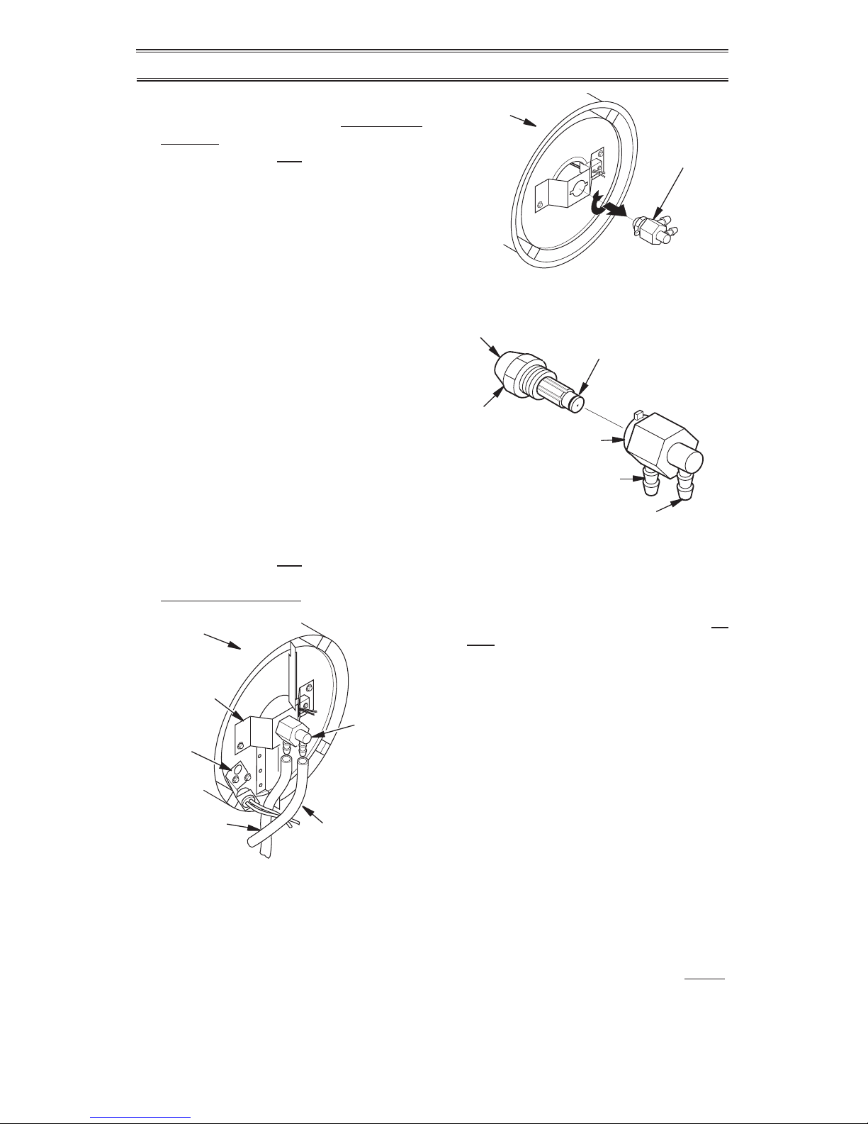
Fuel Filter,
Bushing,
and Lower
Fuel Line
Upper Fuel Line
Side
Cover
Figure 14 - Fuel Filter Removal
FUEL FILTER
1. Remove side cover screws using 5/16"
nut-driver.
2. Remove side cover with a 5/16" nut driver.
On 160, 175 and 220 models, remove two
wheel support bolts and nuts with a Phillips
screwdriver and an adjustable wrench.
the heater to MANUAL MODE, SETTING
5, then press the MODE/RESET button
once. Pump pressure will be displayed
(example: "6.9") for 5 seconds.
4. Adjust pressure. Turn relief valve to right
to increase pressure. Turn relief valve to
left to decrease pressure. See specications with Figure 12 for correct pressure
for each model. DO NOT OVERTIGHTEN
ADJUSTMENT SCREW. Service pump if
pressure can not be adjusted to proper
setting (see Figure 12).
PUMP PRESSURE ADJUSTMENT
(USING BUILT-IN GAUGE)
1. This heater continuously monitors pump
pressure with a built-in pressure sensor.
2. When the heater starts, pump pressure
will be displayed for 6 seconds.
3. To display the pump pressure while operating, operate the heater for 2 minutes, set
Page 15
www.usaprocom.com
15160108-01B
7. Remove ignitor screw with a 1/4" nut
driver. Carefully remove ignitor from
nozzle adapter bracket.
CAUTION: Do not bend or
strike ignitor element. Handle
with care.
8. Carefully remove replacement ignitor from
packing.
9. Carefully guide ignitor into opening in
nozzle adapter bracket. Do not strike
ignitor element. Attach ignitor to nozzle
adapter bracket with screw using a 1/4"
nut driver. Torque 0.90 to 1.69 N-m (8 to
15 in-lbs) Do not over torque.
10. Replace combustion chamber.
11. Route the ignitor wires back down through
the hole in the lower shell. Connect wires
to the ignition control assembly (see Figure 15).
12. Replace fuse on ignition control assembly
with the fuse provided with the SP002-01
Igniter Kit. See Ignition Control Assembly,
page 17.
13. Replace control side cover.
14. Connect and route fuel line hose and air
line hose to nozzle adapter assembly.
15. Replace photocell in photocell bracket.
16. Replace fan (see page 13).
17. Replace fan guard and upper shell (see
page 13).
SERVICE PROCEDURES
Photocell
Bracket
Ignitor
Ignitor Screw/
Washer Assembly
Nozzle
Adapter
Bracket
Ignitor
Element
Combustion
Chamber
Nozzle Adapter
Bracket Opening
Figure 16 - Ignitor SP002-01
Replacement
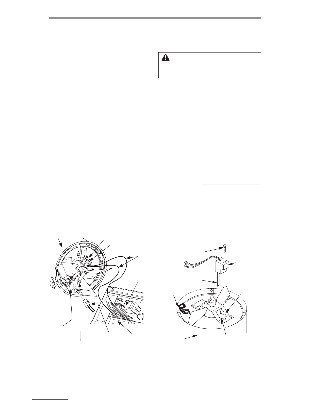
Figure 15 - Disconnecting Ignitor Wires
from Ignition Control Assembly
Photocell
Bracket
Air Line
Hose
Fuel Line
Hose
Combustion
Chamber
Photocell
Assembly
Ignitor
Nozzle Adapter
Bracket
Ignition
Control
Assembly
Side
Cover
Ignitor
Wire
3. Pull upper fuel line off fuel lter neck (see
Figure 14, page 14).
4. Carefully pry bushing, fuel lter, and lower
fuel line out of fuel tank (see Figure 14,
page 14).
5. Wash fuel lter with clean fuel and replace
in tank.
6. Attach upper fuel line to fuel lter neck.
7. Replace side cover.
IGNITOR
1. Remove upper shell and fan guard (See
Upper Shell Removal, page 13).
2. Remove fan (see page 13).
3. Remove the control side cover with a
5/16" nut driver. On 160, 175 and 220
models, remove two wheel support bolts
and nuts with a Phillips screwdriver and
an adjustable wrench. Remove side cover
(see Figure 14).
4. Disconnect ignitor wires from ignition
control assembly (see Figure 15). Pull
the ignitor wires up through the hole in
the lower shell.
5. Disconnect fuel line hose and air line
hose. Remove photocell from photocell
bracket (see Figure 15).
6. Remove combustion chamber. Stand
combustion chamber on end with nozzle
adapter bracket on top (see Figure 16).
Page 16
www.usaprocom.com
160108-01B16
Figure 17 - Removing Air and Fuel Line
Hoses
Fuel Line
Hose
Air Line
Hose
Nozzle/
Adapter
Assembly
Combustion
Chamber
Photocell
Bracket
Nozzle
Adapter
Bracket
NOZZLE ASSEMBLY
1. Remove upper shell (see Upper Shell
Removal, page 13).
2. Remove fan (see Fan, page 13).
3. Remove fuel and air line hoses from
nozzle assembly (see Figure 17).
4. Turn nozzle assembly 1/4 turn to left and
pull toward motor to remove (see Figure
18).
5. Place plastic hex-body into vise and
lightly tighten.
6. Carefully remove nozzle from the nozzle
adapter using 5/8" socket wrench (see
Figure 19).
7. Blow compressed air through face of
nozzle. This will free any dirt in nozzle
area.
8. Inspect nozzle sleeve for damage.
9. Replace nozzle into nozzle adapter until
nozz l e se ats. Tig h t e n 1/3 tur n mo re u s i n g
5/8" socket wrench 4.5 to 5.1 N-m (40 to
45 in-lbs). See Figure 18.
10. Attach nozzle assembly to burner strap
(see Figure 18).
11. Attach fuel and airline hoses to nozzle
assembly.
12. Replace fan (see Fan, page 13).
13. Replace fan guard and upper shell (see
Upper Shell Removal, page 13).
Figure 18 - Removing Nozzle/Adapter
Assembly
Nozzle/
Adapter
Assembly
Combustion
Chamber
Figure 19 - Nozzle and Nozzle Adapter
Nozzle Face
Nozzle
Nozzle Sleeve
Nozzle
Adapter
Air Line
Fitting
Fuel Line
Fitting
(For 220 Model Only)
1. Remove combustion chamber and ignitor
by following steps 1 through 7 under Ig-
nitor, page 15.
2. Carefully place ignitor in a safe location.
3. Remove two nozzle adapter bracket
screws.
4. Place hex-shaped aluminum nozzle
adapter into vise (do not overtighten).
5. Carefully remove nozzle from nozzle
adapter using 5/8" socket wrench (see
Figure 19).
6. Blow compressed air through face of
nozzle. This will remove any debris in
nozzle.
7. Inspect nozzle seal for damage.
8. Replace nozzle into nozzle adapter
until nozzle seats. Tighten 80-110 inch-
pounds.
9. Attach nozzle adapter bracket to combustion chamber with two screws removed in
step 3.
10. Repeat steps 9 through 16 under Ignitor,
page 15.
SERVICE PROCEDURES
Page 17
www.usaprocom.com
17160108-01B
IGNITION CONTROL ASSEMBLY
WARNING: High voltage!
1. Unplug heater.
2. To expose the ignition control assembly,
remove the control panel side cover
screws using 5/16" nut-driver. On 160,
175 and 220 models, remove two wheel
support bolts and nuts with a Phillips
screwdriver and an adjustable wrench.
3. Remove fuse from fuse clips (see Figure
20).
4. Replace fuse with fuse of the same type
and rating (7A, 125VP). Do not substitute
a fuse with a higher current rating.
5. Replace control panel side cover.
Figure 20 - Replacing Fuse
Ignition
Control
Assembly
Fuse
PUMP ROTOR
(Procedure if Rotor is Binding)
1. Remove upper shell (see Upper Shell
Removal, page 13).
2. Remove filter end cover screws using
5/16" nut driver (see Figure 21).
3. Remove filter end cover and air filters.
4. Remove pump plate screws using 5/16"
nut-driver.
5. Remove pump plate.
6. Remove rotor, insert, and blades (see
Figure 22).
7. Check for debris in pump. If debris is
found, blow out with compressed air.
8. Install insert and rotor.
9. Check gap on rotor. Adjust to
0.076/0.101 mm (0.003"/0.004") if needed
(see Figure 22).
Note: Rotate rotor one full turn to ensure
the gap is 0.076/0.101 mm (0.003"/0.004")
at tightest position. Adjust if needed.
Figure 21 - Rotor Location
Pump
Plate
Insert
Rotor
Blade
Filter
End
Cover
Air
Intake
Filter
Air Output Filter
Gap Adjusting
Screw
Rotor
Blade
0.003"/0.004"
(0.076-0.101 mm)
Gap Measured
With Feeler
Gauge
Gap Adjusting Screw
Figure 22 - Gap Adjusting Screw
Locations
Sandpaper
Figure 23 - Sanding Rotor
10. Install blades, pump plate, air filters, and
filter end cover.
11. Replace fan guard and upper shell (see
Upper Shell Removal, page 13).
12. Adjust pump pressure (see Pump Pres-
sure Adjustment, page 14).
Note: If rotor is still binding, proceed as
follows.
13. Perform steps 1 through 6.
14. Place fine grade sandpaper (600 grit) on
flat surface. Sand rotor lightly in “figure 8”
motion four times (see Figure 23).
15. Reinstall insert and rotor.
16. Perform steps 10 through 12.
SERVICE PROCEDURES
Page 18
www.usaprocom.com
160108-01B18
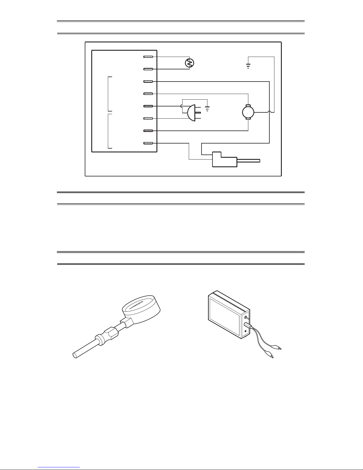
WIRING DIAGRAM
ST002-01
AIR GAUGE KIT
For all models. Special tool to check pump
pressure. 0-15 PSI gauge. 3/8" NPT pipe
thread.
ST001-01
IGNITION CONTROL ASSEMBLY/
PHOTOCELL TESTER
Special tool used to test the ignition control
assembly and photocell.
ACCESSORIES
Purchase these accessories from your local dealer. If they can not supply these accessories,
contact ProCom Heating, Inc. at 1-866-573-0674 for information. You can also write to the
address listed on the back page of this manual.
TECHNICAL SERVICE
You may have further questions about installation, operation, or troubleshooting. If so, contact
ProCom Heating, Inc. at 1-866-573-0674. When calling, please have your model and serial
numbers of your heater ready.
You can also visit ProCom Heating, Inc.’s web site at www.usaprocom.com.
Blue
Main Return
Heater Control Assmebly
Blue
White
White
Black
Ignitor
Red
Photocell
Photocell
Photocell
Ignitor IGN
Motor MTR
Neutral AC
Line (L1) AC
Motor MTR
Ignitor IGN
Ground
Ground
Green
Green
motor
Yellow or White
Yellow or
White
Power Plug
120V/60Hz
Page 19

www.usaprocom.com
19160108-01B
PARTS
WHEEL AND HANDLES
1
3
5
4
6
7
8
9
10
2
ITEM PART # DESCRIPTION 110 160 175 220
1 160074-01 Rear Handle 1 1 1
2 160073-01 Front Handle 1 1 1
3 160072-01 Wheel Support Frame 2 2 2
4 160158-01 Support Bushing 2 2 2
5 160072-12 Fuel Tank Support Assembly 1 1 1
6 160072-13 Screw, M10-1.5 x 60 2 2 2
7 160129-01 Acorn Nut 2 2 2
8 160080-01 Wheel 2 2 2
9 160130-01 Wheel Spacer 2 2 2
10 160079-01 Axle 1 1 1
11 160062-01 Handle 1
12 160064-01 Front Handle Bracket 1
13 160064-02 Rear Handle Bracket 1
14 160083-01 Shell Heat Shield 1
15 160100-01 Screw, 10-16 x 2.0 1
16 160078-01 Screw, 10-16 x 0.5 1
11
13
14
15
16
12
MODELS
PCK160VT
PCK175VT
PCK220VT
MODEL
PCK110VT
Page 20
www.usaprocom.com
160108-01B20
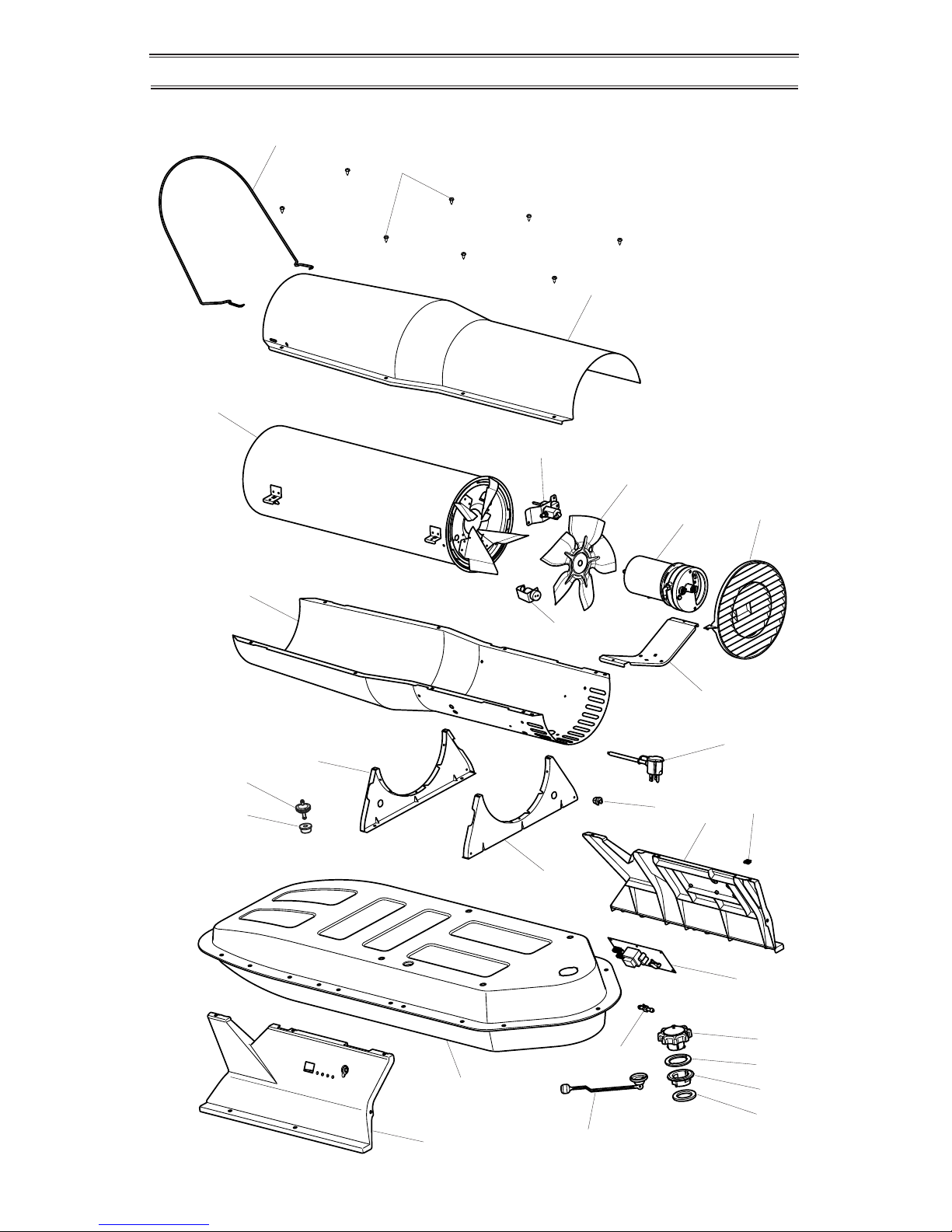
PARTS
MODELS PCK110VT, PCK160VT, PCK175VT AND PCK220VT
12
13
19
20
22
21
23
24
25
26
27
14
14
16
10
15
17
18
3
4
5
6
9
7
8
11
1
2
Page 21

www.usaprocom.com
21160108-01B
ITEM PART NO. DESCRIPTION 110 160 175 220
1 160075-01 Guard Wire 1
1 160075-02 Guard Wire 1 1
1 160075-03 Guard Wire 1
2 160101-01 Shell Screw 8 8 8 8
3 160050-01GY Upper Shell, Painted 1
3 160144-01GY Upper Shell, Painted 1 1
3 160147-01GY Upper Shell, Painted 1
4 160135-01 Combustion Chamber Assy. 1
4 160136-01 Combustion Chamber Assy. 1
4 160137-01 Combustion Chamber Assy. 1
4 160138-01 Combustion Chamber Assy. 1
5 160051-01GY Lower Shell, Painted 1
5 160145-01GY Lower Shell, Painted 1 1
5 160148-01GY Lower Shell, Painted 1
6 see detail, pg 23 Nozzle Bracket Assembly
7 160011-01 Fan 1
7 160058-01 Fan 1 1 1
8 see detail, pg 22 Motor/Pump Assembly
9 see detail, pg 22 Photocell/Bracket Assembly
10 160043-01 Motor Mounting Bracket 1
10 160043-02 Motor Mounting Bracket 1 1 1
11 160066-01 Fan Guard 1
11 160066-02 Fan Guard 1 1 1
12 160012-02 Fuel Filter 1
12 160012-01 Fuel Filter 1 1 1
13 160034-01 Fuel Tube Bushing 1 1 1 1
14 160060-01 Small Shell Bracket 2
14 160060-02 Large Shell Bracket 2 2 2
15 160020-03 Power Supply Cord 1 1 1 1
16 160013-01 Strain Relief Bushing 1 1 1 1
17 160056-01 Right Side Cover 1
17 160056-02 Right Side Cover 1 1 1
18 160087-01 Clip, Nut, #10, .08 Wall 6 6 6 6
19 160055-01 Left Side Cover 1
19 160055-02 Left Side Cover 1 1 1
20 160139-01GY Fuel Tank Assy., Small 1
20 160140-01GY Fuel Tank Assy., Medium 1 1
20 160141-01GY Fuel Tank Assy., Large 1
21 160005-01 Fuel Gauge 1
21 160005-02 Fuel Gauge 1 1 1
22 160037-04 Nylon Airline Tee 1 1 1 1
23 160171-01 Programmed Variable Control 1
23 160171-02 Programmed Variable Control 1 1
23 160171-03 Programmed Variable Control 1
24 160030-01 Vented Fuel Cap Assy. 1 1 1 1
25 160030-03 Vented Fuel Cap Gasket 1 1 1 1
26 160031-01 Plastic Filler Neck 1 1 1 1
27 160036-01 Filler Neck Gasket 1 1 1 1
PARTS AVAILABLE - NOT SHOWN
160037-02 Airline Tubing 2 2 2 2
160039-01 Upper Fuel Line 1 1 1 1
160038-01 Lower Fuel Line 1
160038-02 Lower Fuel Line 1 1 1
160037-03 Control Airline 1 1 1 1
PARTS
This list contains replaceable parts used in your heater. When ordering parts, be sure to provide correct model and serial numbers (from model plate), and part number and description
of desired part.
Page 22
www.usaprocom.com
160108-01B22
1
16
15
14
13
12
11
10
9
8
7
6
5
4
3
2
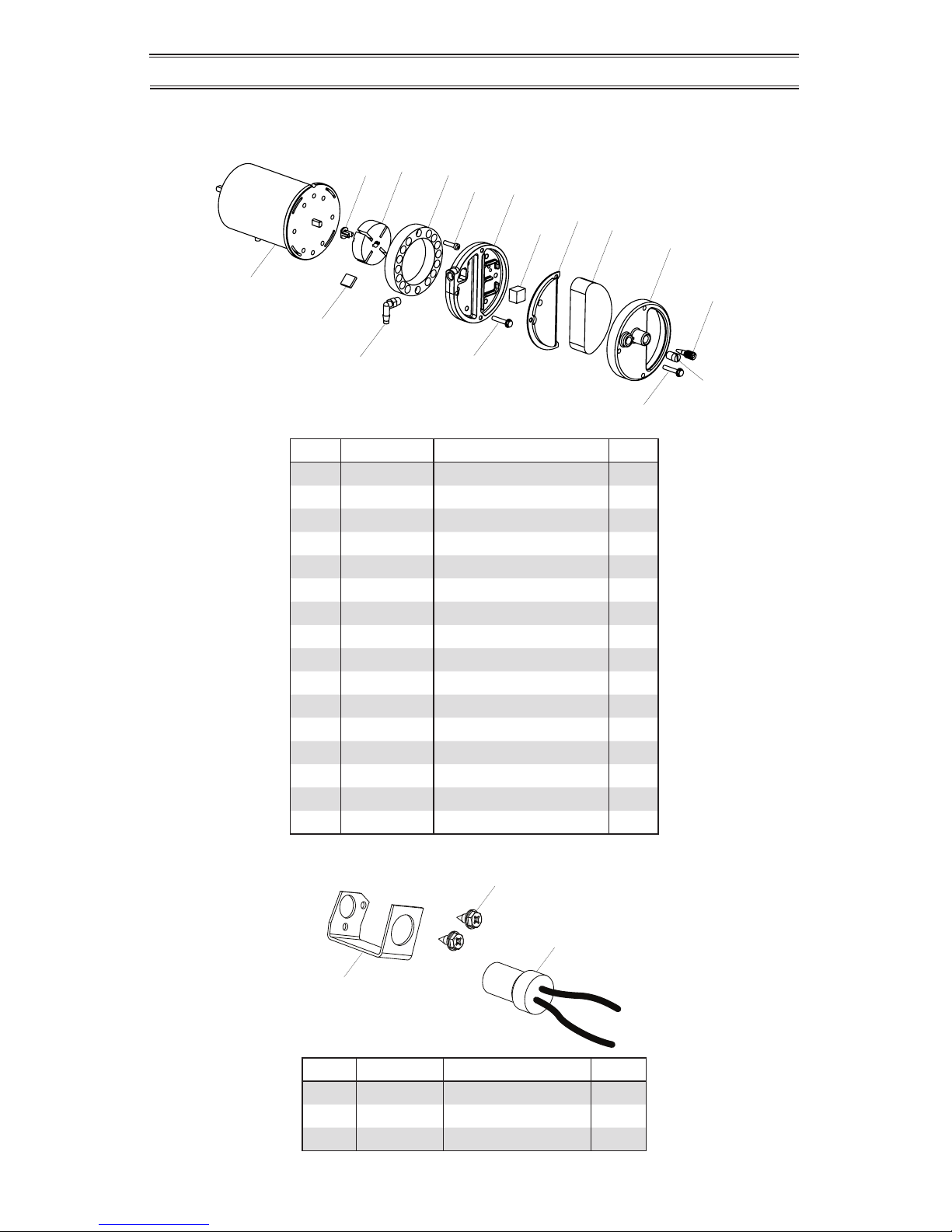
PHOTOCELL ASSEMBLY
1
2
3
ITEM PART # DESCRIPTION QTY
1 160041-03 Photocell Bracket 1
2 160092-02 Screw, 6-32 x .38 2
3 160016-01 Photocell Assembly 1
ITEM PART # DESCRIPTION QTY
1 160001-01 Motor 1
2 160023-01 Rotor Insert 1
3 160003-01 Pump Rotor 1
4 160006-01 Pump Body 1
5 160088-01 Screw, 10-32 x .62 2
6 160007-01 Pump Cover 1
7 160009-01 Lint Filter 1
8 160008-01 Output Filter Assembly 1
9 160010-01 Intake Filter 1
10 160057-01 Filter End Cover 1
11 160106-01 Adjusting Screw 1
12 160024-01 Pipe Plug 1
13 160090-01 Screw, 10-32 x 1.0 3
14 160089-01 Screw, 10-32 x 1.12 6
15 160029-01 90° Nylon Elbow 1
16 160004-01 Pump Blade 4
PARTS
MOTOR AND PUMP ASSEMBLY
MODELS PCK110VT, PCK160VT, PCK175VT AND PCK220VT
Page 23
www.usaprocom.com
23160108-01B
2
4
5
6
10
9
8
7
3
1
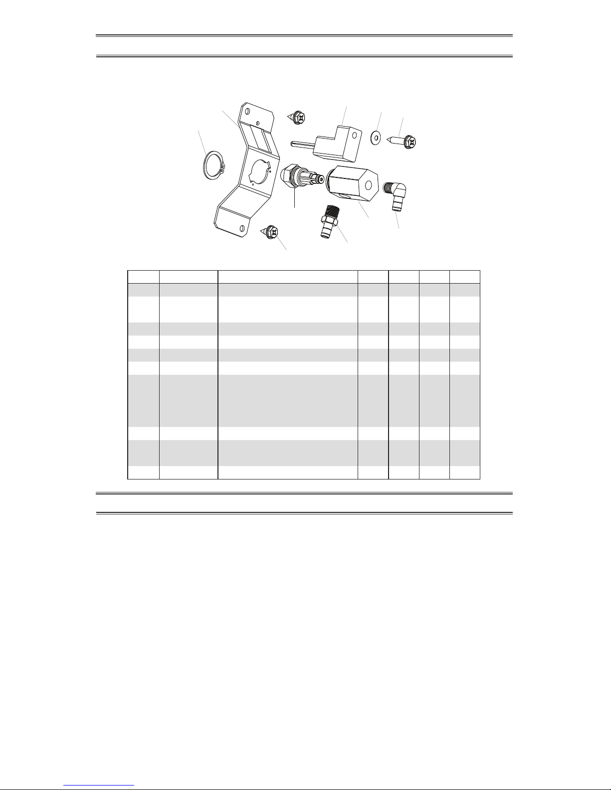
PARTS
NOZZLE ASSEMBLY
MODELS PCK110VT, PCK160VT, PCK175VT AND PCK220VT
ITEM PART # DESCRIPTION 110 160 175 220
1 160086-01 Stainless Steel Retaining Ring 1
2 160042-01 Nozzle Adapter Bracket 1 1 1
2 160042-02 Nozzle Adapter Bracket 1
3 160102-01 Screw, 10-16 x .38 2 2 2 2
4 160002-01 Ignitor 1 1 1 1
5 160093-01 Belleville Washer 1 1 1 1
6 160092-01 Screw, 6-32 x .88 1 1 1 1
7 160040-32 Nozzle Assembly 1
7 160040-20 Nozzle Assembly 1
7 160040-39 Nozzle Assembly 1
7 160040-41 Nozzle Assembly 1
8 160077-01 Brass Barb Fitting 1
9 160028-01 Nozzle Adapter 1 1 1
9 160028-02 Nozzle Adapter 1
10 160077-02 Barb Fitting, 90° 1
REPLACEMENT PARTS
Contact authorized dealers of this product.
If they can’t supply original replacement
parts, call ProCom Heating, Inc. toll free at
1-866-573-6074 for referral information.
When calling have ready:
• Your name
• Your address
• Model and serial number of your heater
• How heater was malfunctioning
• Type of gas used (Propane/LP or Natural
gas/NG) and Propane/LP tank size
• Purchase date
• Place of purchase
Usually, we will ask you to return the defective
part to the factory. You may be asked to supply
proof of purchase.
Note: Use only original replacement parts. This will protect your warranty coverage for parts
replaced under warranty.
PARTS UNDER WARRANTY
PARTS NOT UNDER WARRANTY
Contact authorized dealers of this product.
If they can’t supply original replacement
part(s) call ProCom Heating, Inc. toll free at
1-866-573-6074 for referral information.
When calling have ready:
• Model and serial number of your heater
• The replacement part number
Page 24

REGISTER YOUR PRODUCT AT WWW.USAPROCOM.COM
PROCOM HEATING, INC. LIMITED WARRANTIES
New Products – Outdoor Heating
Standard Warranty: ProCom Heating, Inc. warrants this new product and any parts thereof to be free from
defects in material and workmanship for a period of one (1) year from the date of rst purchase from an
authorized dealer provided the product has been installed, maintained and operated in accordance with
ProCom Heating, Inc.’s warnings and Instructions.
For products purchased for commercial, industrial or rental usage, this warranty is limited to 90 days from
the date of rst purchase.
Factory Reconditioned Products
Limited Warranty: ProCom Heating, Inc. warrants factory reconditioned products and any parts thereof to
be free from defects in material and workmanship for a period 30 days from the date of rst purchase from an
authorized dealer provided the product has been installed, maintained and operated in accordance with ProCom
Heating, Inc.’s warnings and Instructions. No return will be authorized. Parts will be provided to repair the product.
Terms Common to All Warranties
The following terms apply to all of the above warranties:
Always specify model number and serial number when contacting the manufacturer. To make a claim under
this warranty, the bill of sale or other proof of purchase must be presented.
This warranty is extended only to the original retail purchaser when purchased from an authorized dealer,
and only when installed by a qualied installer in accordance with all local codes and instructions furnished
with this product.
This warranty covers the cost of part(s) required to restore this product to proper operating condition and
an allowance for labor when provided by a ProCom Heating, Inc. Authorized Service Center or a provider
approved by ProCom Heating, Inc. Warranty parts must be obtained through authorized dealers of this
product and/or ProCom Heating, Inc. who will provide original factory replacement parts. Failure to use
original factory replacement parts will void this warranty.
Traveling, handling, transportation, diagnostic, material, labor and incidental costs associated with warranty
repairs, unless expressly covered by this warranty, are not reimbursable under this warranty and are the
responsibility of the owner.
Excluded from this warranty are products or parts that fail or become damaged due to misuse, accidents,
improper installation, lack of proper maintenance, tampering or alteration(s).
This is ProCom Heating, Inc.’s exclusive warranty, and to the full extent allowed by law; this express warranty excludes any and all other warranties, express or implied, written or verbal and limits the duration of
any and all implied warranties, including warranties of merchantability and tness for a particular purpose to
one (1) year on new products and 30 days on factory reconditioned products from the date of rst purchase.
ProCom Heating, Inc. makes no other warranties regarding this product.
ProCom Heating, Inc.’s liability is limited to the purchase price of the product and ProCom Heating, Inc.
shall not be liable for any other damages whatsoever under any circumstances including direct, indirect,
incidental, or consequential damages.
Some States do not allow limitations on how long an implied warranty lasts or the exclusion or limitation of
incidental or consequential damages, so the above limitation or exclusion may not apply to you.
This warranty gives you specic legal rights, and you may also have other rights which vary from state to state.
WARRANTY
KEEP THIS WARRANTY
Model (
located on product or identication tag
) _____________________________
Serial No. (
located on product or identication tag
) __________________________
Date Purchased ______________________________________
Keep receipt for warranty verication.
160108-01
Rev. B
08/13
ProCom Heating, Inc.
Bowling Green, KY 42101
www.usaprocom.com
1-866-573-0674
Page 25

IMPORTANTE: Lea y comprenda este manual antes de
ensamblar, encender o dar servicio al calentador. El
uso inadecuado del calentador puede causar lesiones
graves. Conserve este manual para referencias futuras.
Nunca utilice el calentador en dormitorios o salas de
estar y para el uso en combustible pisos.
Calentador apto para uso en exteriores.
CALENTADORES PORTÁTILES DE AIRE FORZADO
CALENTADOR DE KEROSENO/DIESEL CON TERMOSTATO
INCORPORADO
MANUAL DEL PROPIETARIO
PCK110VT - AJUSTABLE 80-110,000 BTU/H
PCK160VT - AJUSTABLE 110-160,000 BTU/H
PCK175VT - AJUSTABLE 125-175,000 BTU/H
PCK220VT - AJUSTABLE 160-220,000 BTU/H
¿Preguntas, problemas, piezas faltantes? Antes de volver a la tienda, llame a
nuestro Departamento de Servicio al Cliente al 1-866-573-0674, de lunes a viernes de
7:30 a.m. a 4:15 p.m., Hora del Centro, o envíe un correo electrónico a
customerservice@usaprocom.com.
Page 26

www.usaprocom.com
160108-01B26
referencia. Es su guía para la operación segura y correcta de este calentador.
1. Utilice sólo keroseno, diesel/aceite com-
bustible Nº 1 ó Nº 2, bien o combustible
de aviación JET A o JP-8 para evitar el
riesgo de incendio o explosión. Nunca
utilice gasolina, aceite usado de cárter,
nafta, disolventes de pintura, alcohol u
otros combustibles altamente inamables.
2. Carga de combustible
a) El personal que realice la carga de
combustible debe ser idóneo para
esta tarea y conocer a profundidad
las instrucciones del fabricante y las
normas vigentes acerca de la carga
de combustible de calentadores en
condiciones de seguridad.
b) Sólo debe utilizarse el tipo de combus-
tible indicado en la placa de datos del
calentador.
c) Antes de cargar combustible, es nece-
sario apagar cualquier llama y esperar
a que el calentador se enfríe.
d) Durante la carga de combustible, todos
los circuitos de combustible y sus conexiones deben inspeccionarse para
comprobar que no existan fugas. Toda
fuga deberá repararse antes de volver
a utilizar el calentador.
e) Bajo ninguna circunstancia se deberá
guardar el suministro diario de combustible del calentador en una construcción
cercana al equipo. Los grandes volúmenes de combustible deben guardarse en
el exterior de la estructura.
f) Todo lugar de almacenamiento de com-
bustible debe situarse a una distancia
de 7.62 m (25 pies) como mínimo de
calentadores, antorchas, equipos de
soldadura y otras fuentes de ignición
similares (excepción: el depósito de
ADVERTENCIA:Este producto contiene o genera químicos
reconocidos por el estado de California como causantes de cáncer o de defectos de nacimiento,
u otros daños reproductivos.
IMPORTANTE: Lea este manual
del propietario cuidadosa y
completamente antes de intentar
ensamblar, operar o dar servicio
a este calentador. El uso inadecuado de este calentador puede
causar lesiones graves o la muerte
por quemaduras, incendio, explosión, electrocución e intoxicación
con monóxido de carbono.
PELIGRO: ¡La intoxicación
con monóxido de carbono puede
resultar en la muerte!
Intoxicación por monóxido de carbono:
Los primeros síntomas de intoxicación por
monóxido de carbono son similares a los
de la gripe e incluyen jaqueca, mareos o
náuseas. Si usted presenta estos síntomas,
es posible que el calentador no esté funcionando correctamente. ¡Respire aire fresco
inmediatamente! Haga que se le dé servicio
al calentador. El monóxido de carbono afecta
más algunas personas que a otras. Las más
afectadas son mujeres embarazadas, personas con enfermedades del corazón o de los
pulmones o anemia, aquellas bajo la inuencia del alcohol y aquellas a grandes altitudes.
Asegúrese de leer y comprender todas las
advertencias. Conserve este manual como
SEGURIDAD
TABLA DE CONTENIDOS
Seguridad ................................................ 26
Desempaque ........................................... 28
Ensamble................................................. 28
Identicación del producto y
ubicación de la etiqueta ..................... 30
Especicaciones ..................................... 31
Combustibles ........................................... 31
Funcionamiento ....................................... 32
Ventilación ............................................... 32
Funcionamiento con generador portátil ... 34
Almacenamiento, transporte y envío ....... 34
Programa de mantenimiento preventivo .... 35
Solución de problemas ............................ 35
Procedimientos de servicio...................... 40
Diagrama de cableado ............................ 45
Servicio técnico ....................................... 46
Accesorios ............................................... 46
Piezas de repuesto .................................. 46
Piezas ...................................................... 47
Garantía................................................... 52
Page 27

www.usaprocom.com
27160108-01B
SEGURIDAD
combustible integrado al calentador
o todo tanque auxiliar autorizado que
esté conectado al equipo).
g) De ser posible, el combustible debe
almacenarse en áreas en las que la
penetración del suelo no permita que se
ltre o se encienda a causa de un fuego
proveniente de un lugar menos elevado.
h) El almacenamiento de combustible
debe cumplir con las disposiciones de
la autoridad competente.
3. Use solamente la tensión eléctrica y la
frecuencia que se especican en la placa
donde aparece al número de modelo.
4. El calentador es apto para su uso en
exteriores.
5. El calentador debe tener una conexión
a tierra. Utilice únicamente un cable de
extensión trilar correctamente conectado a tierra. Enchúfelo solomente en un
tomacorriente con conexión a tierra.
6. Utilice el equipo sólo en áreas sin vapores
inamables ni alta densidad de polvo.
7. Distancia mínima de materiales combustibles: 2.44 m (8 pies) desde la salida de
aire caliente, 1.83 m (6 pies) desde la
parte superior y 1.20 m (4 pies) desde
los laterales y la entrada de la unidad.
8. Sitúe el calentador sobre una supercie
estable y nivelada mientras está caliente
o en funcionamiento, pues de lo contrario
puede originarse un incendio.
9. El calentador puede utilizarse en pisos
tales como de madera (un material combustible).
10. Úsese solamente en áreas bien ventiladas.
Antes de usar el calentador, asegúrese
de disponer de una abertura de al menos
2800 cm2 (tres pies cuadrados) que permita la entrada de aire fresco por cada 30
kw (100,000 BTU/h) de clasicación.
11. Mantenga alejados a los niños y los animales en todo momento.
12. Nunca encienda el calentador cuando la
cámara de combustión esté caliente o
cuando se haya acumulado combustible
en ella.
13. Este calentador está equipado con termostato. El calentador puede empezar a
funcionar en cualquier momento.
14. Nunca deje el calentador conectado sin la
supervisión de un adulto si es probable la
presencia de niños o animales en el área.
15. Tenga precaución cuando mueva o almacene el calentador si el tanque aún
contienen combustible. Puede ocurrir un
derrame de combustible.
16. El calentador debe utilizarse sólo de acuerdo con las normas y códigos locales. Los
residentes de Canadá deben consultar la
norma CSA B139, Código de instalación
para equipo de combustión de petróleo
para obtener información sobre el procedimiento de instalación recomendado.
17. Nunco utilice gasolina, aceite usado
de cárter, nafta, disolventes de pintura,
alcohol u otros combustibles altamente
inamables.
18. Nunca utilice el calentador en áreas con
gasolina, disolvente de pintura u otros
vapores altamente inamables.
19. Nunca utilice el calentador en dormitorios
o salas de estar.
20. Nunca mueva, maneje, cargue combustible ni repare un calentador en funcionamiento, caliente o conectado.
21. Nunca conecte conductos a la parte anterior o posterior del calentador.
22. Los calentadores que se usen cerca de
lonas impermeables y toldos o materiales
protectores parecidos deben colocarse
a una distancia segura con respecto a
dichos materiales. La distancia mínima
recomendada es de 3.048 m (10 pies).
Se recomienda expresamente que tales
materiales protectores sean retardadores
del fuego. Estos materiales protectores
deben estar bien asegurados para evitar
que se enciendan o que bloqueen el calentador a causa de la acción del viento.
23. Desenchufe el calentador cuando no está
en uso.
24. Nunca bloquee la entrada de aire (parte
posterior) ni la salida de aire (parte anterior) del calentador.
25. Advertencia para los residentes de la
ciudad de Nueva York
El equipo sólo debe utilizarse en obras
de construcción de conformidad con
las disposiciones de los códigos de NYC
vigentes.
26. No use nunca fuentes de combustible
externas ni tanques que no hayan sido
diseñados especícamente para utilizarse
con este calentador.
Page 28

www.usaprocom.com
160108-01B28
RUEDA DE ENSAMBLADO
Los modelos 160, 175 y 220
1. Deslice el eje (A) a través de agujeros en el bastidor de soporte de la rueda.
2. Deslice el espaciador de la rueda (B) y la rueda (D) (lado cóncavo hacia afuera) sobre el eje.
3. Fijar la tuerca (C) al extremo del eje.
4. Repita los pasos 2 y 3 para el lado opuesto, a continuación, apretar las tuercas con una
llave ajustable.
DESEMPAQUE
Figura 1 - Guarda de alambre trasladó a
posición de bloqueo
1. Saque todos los materiales en los que se
empacó el calentador para el envío.
2. Saque todas las piezas de la caja.
3. Revise el calentador para ver si hay algún
daño debido al transporte. Si el calentador está dañado, llame a ProCom Heating, Inc. al 1-866-573-0674 para obtener
piezas de repuesto antes de devolverlo al
distribuidor.
ENSAMBLE
ALAMBRE GUARDIA
Todos los Modelos
Tire del protector hacia la parte delantera del
calentador hasta que encaje en su lugar en
las ranuras de ambos lados de la cubierta
superior.
Figura 2 - Montaje de la rueda, los modelos 160, 175 y 220
Del eje (A)
Acorn
tuerca (C)
Rueda (D)
Espaciador (B)
Page 29

www.usaprocom.com
29160108-01B
MANEJAR LA ASAMBLEA
Los modelos 160, 175 y 220
1. Deslice el mango trasero (E) en el marco de soporte. Inserte los tornillos (G) e instale las
tuercas (F).
2. Coloque la manija frontal (I) debajo de la brida del tanque de combustible y colocar 4
tornillos (J) de la parte superior de brida a través de agujeros en la brida en los agujeros
en la manija. Coloque las contratuercas (H) y apriete.
ENSAMBLE
Figura 3 - Manija, los modelos 160, 175 y 220
Mango trasero (E)
Tornillo, 10-24 x 1,5 (G)
Tuerca 10-24 (F)
Tornillo 1/4-20 x 1.75 “(J)
Mango delantero (I)
Page 30

www.usaprocom.com
160108-01B30
IDENTIFICACIÓN DEL PRODUCTO Y UBICACIÓN DE LA ETIQUETA
Etiqueta de
advertencia
Inglés
160110-01
Etiqueta de
advertencia francés
160110-02
Etiqueta de
advertencia
español
160110-03
Todos los Modelos
Lateral Derecho
(220 Modelo se
muestra)
Llenado de
combustible etiqueta
Parte N º 160168-01
Etiqueta para el control
Parte N º 160167-02
CSA etiqueta
Parte N º 160111-04, 110 modelo
Parte N º. 160112-02, 160 modelo
Parte N º 160112-03, 175 modelo
Parte N º 160112-05, 220 modelo
Etiqueta
funcionamiento
Parte N º 160173-01
Códigos funcionamiento
etiquetas
Parte N º 160174-01
Mantenimiento Etiqueta
Parte N º 160175-01
Atención Etiqueta
Parte N º 160172-01
Figura 4 - Identicación del producto y ubicación de las etiquetas
Nueva York, MA y
CA información de
la etiqueta
Parte N º 160169-01
Todos los modelos
lateral Izquierdo
(110 Modelo se
muestra)
Frente
Manejar
(160, 175 y
220 modelos)
Aire
caliente
salida
Controle
panel
Trasero
Manejar
(160, 175
y 220
modelos)
Alambre
guardia
Superior manejar
(Modelo 110)
Tanque del
combustible
Aire frío
entrada
Cable
eléctrico
Tapa del
combustible
Indicador de
combustible
Aire
caliente
salida
Page 31

www.usaprocom.com
31160108-01B
ESPECIFICACIONES
COMBUSTIBLES
* El uso de diesel o aceite combustible Nº 2 en
temperaturas extremadamente bajas puede
requerir aditivos anticongelantes no tóxicos.
No utilice combustibles con densidad mayor
a 2 ni aceites pesados como el aceite usado
procedente del cárter. Este tipo de aceites
pesados entra en combustión de forma inadecuada y contamina el calentador.
IMPORTANTE: Utilice un contenedor EXCLUSIVO PARA KEROSENO (azul) o
EXCLUSIVO PARA DIESEL (amarillo) para
almacenar estos combustibles. Asegúrese de
que el contenedor esté limpio. Los elementos
extraños como el óxido, la suciedad o el agua
pueden causar que el sistema de control de
encendido apague el calentador. Asimismo,
requerirá la limpieza frecuente del sistema de
combustible del calentador.
PCK110VT PCK160VT PCK175VT PCK220VT
Potencia de salida 80K-110K 110K-160K 125K-175K 160K-220K
Combustible (todos los
modelos)
Use solamente keroseno, diesel/aceite combustible #1 ó #2,
combustible de aviación JET A o JP-8*
Capacidad de combustible 5,5 gal/20,8 L 10 gal/37,9 L 10 gal/37,9 L 14 gal/53 L
Consumo de combustible
(por hora)
0,82 gal/3,1 L 1,19 gal/4,5 L 1,3 gal/4,9 L 1,64 gal/6,2 L
La bomba de presión 6,9 PSI
(caliente)
6,7 PSI
(caliente)
6,8 PSI
(caliente)
8,4 PSI
(caliente)
Requerimientos eléctricos 120 V/60 HZ 120 V/60 HZ 120 V/60 HZ 120 V/60 HZ
Amperaje (funcionamiento
normal)
2,9 3,2 3,4 4,6
Velocidad típica del motor 3400 RPM 3400 RPM 3400 RPM 3400 RPM
Motor 1/4 hp 1/4 hp 1/4 hp 1/4 hp
Peso de envío 42 lbs/19 kg 71 lbs/32,2 kg 71 lbs/32,2 kg 77 lbs/35 kg
Peso del calentador sin
combustible (aprox)
36 lbs/16,3 kg
60,5 lbs/27,4 kg 60,5 lbs/27,4 kg 66 lbs/29,9 kg
ADVERTENCIA: Utilice sólo
keroseno, diesel/aceite combustible Nº 1 ó Nº 2, o bien combustible de aviación JET A o JP-8
para evitar el riesgo de incendio
o explosión. Nunca utilice gasolina, aceite usado de cárter,
nafta, disolventes de pintura,
alcohol u otros combustibles
altamente inamables.
Utilice sólo keroseno, diesel*/aceite combustible Nº 1/Nº 2, o bien combustible de
aviación JET A o JP-8. También pueden
utilizarse combustibles más pesados como
aceite combustible Nº 2 o diesel Nº 2, aunque
el efecto será:
• olor penetrante
• mantenimiento adicional del ltro de com-
bustible
Page 32

www.usaprocom.com
160108-01B32
IMPORTANTE: Revise y asegúrese de comprender las advertencias indicadas en la sección
Seguridad de la página 26. Son
necesarias para hacer funcionar
este calentador de manera segura.
Al utilizar el calentador, siga todas
las ordenanzas y códigos locales.
PARA ENCENDER EL
CALENTADOR
1. Asegúrese de cumplir con todas las medidas de ventilación y seguridad.
2. Sitúe el calentador de forma tal que brinde
la máxima circulación de aire caliente.
Siga todos los requisitos de ubicación
indicados en la sección Seguridad de la
página 26.
3. Llene el tanque con combustible y adjunte
la tapa del combustible. Utilice sólo keroseno, diesel/aceite combustible Nº 1 o Nº
2, o bien combustible de aviación JET A
o JP-8 para evitar el riesgo de incendio o
explosión. Nunca utilice gasolina, aceite
usado de cárter, nafta, disolventes de
pintura, alcohol u otros combustibles
inamables.
4. Conecte el cable de alimentación del
calentador a un cable de extensión trilar
aprobado y con conexión a tierra. El cable
de extensión debe tener una longitud de
1,8 m (seis pies) como mínimo.
Requisitos de tamaño del cable de
extensión
• 1,8 a 3 m (6 a 10 pies) de longitud: utilice
un cable 18 AWG (0,75 mm2)
• 3,3 a 30.5 m (11 a 100 pies) de longitud:
utilice un cable 16 AWG (1 mm2)
• 30,8 a 61 m (101 a 200 pies) de longitud:
utilice un cable 14 AWG (1,5 mm2)
5. Conecte el cable de extensión un toma-
corriente estándar de tres oricios de 120
voltios/60 hertz con conexión a tierra.
6. Presione ON/STOP para ON. Una alarma
sonará y la pantalla comenzará cuenta
atrás para la ignición. El calentador se
iniciará y presión de la bomba se visualizará durante 6 segundos.
7. Presione MODE / RESET para seleccionar el modo de funcionamiento deseado.
Nota: Cuando se opera en el modo de
termostato, presione el botón MODE /
RESET una vez para cambiar al modo
manual. Cuando se opera en modo manual, pulse el botón MODE / RESET dos
veces antes de 5 segundos para cambiar
al modo de termostato.
FUNCIONAMIENTO
VENTILACIÓN
Ejemplo: Un calentador de 220 000 BTU/h
(64,5 kw) requiere una de las siguientes
opciones:
• una puerta de garaje para dos autos
[abertura de 4,88 metros (16 pies)] con
una elevación de 12,7 cm (5")
• una puerta de garaje para un auto [abertura
de 2,74 metros (9 pies)] con una elevación
de 22,9 cm (9")
• dos ventanas de 76,2 cm (30") con una
elevación de 40,6 cm (16")
ADVERTENCIA: Asegúrese
de que exista una abertura que
permita la entrada de aire fresco
de 2,800 cm2 (3 pies cuadrados) como mínimo por cada
100,000 BTU/h de clasicación.
Proporcione aire fresco adicional si se utilizan más calentadores. Es necesario cumplir con
los requisitos mínimos de ventilación para evitar los riesgos
vinculados con la intoxicación
por monóxido de carbono. Veri-
que el cumplimiento de estos
requisitos antes de utilizar el
calentador.
Page 33

www.usaprocom.com
33160108-01B
ASSEMBLED IN THE USA BY:
ASSEMBLE AUX ETATS-UNIS PAR:
ENSAMBLADA EN LOS EE.UU.POR:
PROCOM HEATING, INC.
2800 GRIFFIN DRIVE
BOWLING GREEN, KY 42101
`
THERMOSTAT MODE
MODE/RESET
PUMP PRESSURE
STAND BY
ON/STOP
TEMPERATURE
MANUAL MODE
MODE MANUEL/MODO MANUAL
MODE/REINITIALISATION
`
MARCHE/ARRET
^
MODE THERMOSTAT
THERMOSTATO MODO
MODO/RESTABLECER
ENCENDER/APAGAR
TEMPERATURA
160167-02
PRESSION DE LA POMPE
PRESION DE BOMBA
`
ADJUST
AJUSTE
Pantalla LED mostrará la temperatura del entorno, a menos arriba y hacia abajo las teclas
de echa se presionan. Después de pulsar
estas teclas, la pantalla muestra la temperatura
del punto de ajuste por cinco segundos y luego
volver a visualizar la temperatura del entorno.
La exposición a la luz directa del sol o el frío
extremo puede afectar a la lectura de temperatura y / o el funcionamiento del termostato.
Este termostato se almacenará el último
punto establecido, incluso si se desconecta
la alimentación. La unidad se mantenga este
punto de ajuste hasta que un nuevo punto de
ajuste se introduce.
CÓDIGOS DE ERROR
Este calentador se muestran códigos de error
cada vez que hay una parada de control. Consulte las páginas Solución de problemas, de
35 a 39, antes de tratar de recticar cualquier
roblema con el calentador.
En el modo manual LED: Ajuste de
salida a la conguración disired. Pulse
para aumentar la producción de BTU.
Pulse para reducir la salida de BTU.
Nota: Después del arranque, el calentador
de producción de BTU se puede ajustar
de inmediato, pero los ajustes no tendrán
efecto durante 2 minutos. Esto permite
que el calentador se estabilice.
Modo termostato LED encendido:
Ajuste el termostato presionando para
cambiar el punto de referencia superior. Pulse para cambiar el punto de
referencia inferior. Si la temperatura de
referencia del termostato es mayor que
la temperatura del aire circundante en
un 3° F, el calentador se enciende. Si la
temperatura de referencia del termostato
es inferior a la temperatura ambiente del
aire, el calentador no enciende. Potencia
del calentador se ajustará automáticamente para mantener la temperatura
programada.
ADVERTENCIA: El calentador
está equipado con termostato.
El calentador puede comenzar a
funcionar en cualquier momento.
PARA DETENER EL
CALENTADOR
1. Pulse el botón ON/STOP para detener la
calefacción.
2. Desconecte el calentador cuando no esté
en uso.
PARA REESTABLECER EL
CALENTADOR
1. Espere dos minutos antes de reiniciar.
2. Presione MODE/RESET para reiniciar el
calentador.
FUNCIONAMIENTO
Figura 5 - Controles de Pantalla
Page 34

www.usaprocom.com
160108-01B34
FUNCIONAMIENTO CON GENERADOR PORTÁTIL
ADVERTENCIA: Antes de
utilizar el calentador o cualquier
dispositivo de un generador por-
tátil, verique que el generador
se encuentre correctamente conectado a tierra. La falta de una
conexión a tierra o la existencia
de una conexión defectuosa pueden ocasionar una electrocución
ante una falla. Consulte el manual
del propietario suministrado por
el fabricante del generador para
obtener información sobre los
procedimientos de conexión a
tierra correctos.
La tensión de funcionamiento del calentador
puede variar de 108 a 132 voltios (120 voltios
+/- 10%). Antes de conectar el calentador al
generador es necesario vericar la tensión de
salida del generador (si el generador cuenta
con una función de suspensión automática,
ALMACENAMIENTO, TRANSPORTE Y ENVÍO
3. Deseche como corresponda el combustible usado. Consulte a las estaciones de
servicio locales que reciclan combustibles.
4. Si desea guardar el calentador, asegúrese
de que sea en un lugar seco. Verique
que en el lugar no haya polvo ni vapores
corrosivos.
IMPORTANTE: No almacene keroseno durante los meses de verano para usarlo en
la próxima estación de calor. El combustible
usado puede dañar el calentador.
la tensión de salida debe medirse mientras
éste funciona a máxima velocidad). Si la
tensión no se encuadra dentro de los valores
indicados, el calentador no debe conectarse
al generador.
Consulte la sección Funcionamiento en la página 32 para conocer los procedimientos para
encender, detener y reajustar el calentador.
Nota: En caso de envío, las empresas de
transporte requieren que el tanque de combustible esté vacío.
1. Extraiga el excedente de combustible por
medio de un sifón. Drene el combustible
restante a través de relleno cuello por el
calentador de inexión en la parte trasera.
2. Si nota que hay residuos en el combustible viejo, agregue 1 ó 2 cuartos de keroseno limpio al tanque, agítelo y vuelva
a vaciar. De esta forma evitará que el
exceso de residuos obstruya los ltros
en el futuro.
Cable a tierra (Nº 10 AWG Cobre trenzado)
Puesta a
tierra de
cobre o
bronce
Figura 6 - Método de conexión a tierra
habitual del generador (la estructura del
generador puede diferir de la imagen
que se muestra)
Alternador
Terminal de
conexión a
tierra
Page 35

www.usaprocom.com
35160108-01B
PROGRAMA DE MANTENIMIENTO PREVENTIVO
ADVERTENCIA: No repare el calentador mientras está enchufado,
en funcionamiento o caliente. Pueden ocurrir quemaduras graves
y electrocución.
Artículo Frecuencia Método
Tanque de combustible
Limpie en cada estación o según sea
necesario.
Consulte la sección Almace-
namiento, transporte y envío,
página 34.
Filtros de salida de
aire y partículas
Reemplace cada 500 horas de uso o una
vez al año.
Consulte Filtros de salida
de aire, entrada de aire y de
pelusa, página 40.
Filtro de entrada
de aire
Lave y seque con agua y jabón cada 500
horas de uso o según sea necesario.
Consulte Filtros de salida
de aire, entrada de aire y de
pelusa, página 40.
Filtro de combustible
Limpie dos veces en cada estación que requiera calefacción o según sea necesario.
Consulte Filtro de combusti-
ble, página 42.
Aspas del ventilador
Limpie en cada estación o según sea
necesario.
Consulte Ventilador, página 40.
Motor No requiere mantenimiento: lubricación
permanente.
SOLUCIÓN DE PROBLEMAS
ADVERTENCIA: No repare el calentador mientras está enchufado,
en funcionamiento o caliente. Pueden ocurrir quemaduras graves
y electrocución.
ADVERTENCIA: Alta tensión! Desenchufar calentador antes de
dar servicio.
DISPLAY POSIBLE CAUSA RECURSO
La pantalla muestra
C1,C2,C3,C4,C5,C6,
C7,C8 or C9.
1. Recuerda los códigos de control de la operación anterior.
1. Pulse el botón MODE/RESET Para borrar el código y
reinicie calentador.
La pantalla está apagada. 1. No hay energía en calefac-
ción (todas Los LED están
apagados).
2. Mala conexión eléctrica entre
el control y el poder cable.
1. Verique las conexiones del
cable de alimentación.
2. Desconecte el calentador.
Marque todas las conexiones
eléctricas. (ver Diagrama de
cableado, página 45).
CONDICIÓN DE FALLO
El motor no arranca después de calentador conectado y en ON / STOP
está activada.
Page 36

www.usaprocom.com
160108-01B36
SOLUCIÓN DE PROBLEMAS
La pantalla muestra el
ambiente temperatura.
1. Ajuste del termostato es muy
bajo.
1. Ajuste el termostato a una
posición más alta pulsando el
botón o cambiar al modo
manual pulsando el botón
MODE/RESET
La pantalla muestra C1.
La tensión es alta.
1. La tensión de alimentación
es superior a 135 voltios. El
generador no regula adecuadamente.
1. Compruebe la tensión de
alimentación es inferior a 135
voltios.
La pantalla muestra el C2.
de Baja Tensión.
1. La tensión de alimentación
es inferior a 95 voltios. Circuito de alimentación de baja
calidad o cable de extensión
demasiado largo o calibre
inadecuado.
1. Compruebe la tensión de
alimentación es más de 95
voltios. Vea los requisitos de
cable de extensión eléctrica
en la página 32.
La pantalla muestra el
C8. Temperatura superior
a 100 ° F.
1. La temperatura ambiente
supera los 100 ° F.
1. Funcionar el calefactor en un
ambiente más fresco.
La pantalla muestra C9.
Bomba de baja presión.
1. Mala conexión eléctrica entre
el motor y el cable de alimentación.
2. Motor bloqueado. El ventilador está obstruido.
3. La bomba no está libre para
girar.
4. El motor está defectuoso.
1. Desconecte el calentador.
Revise todas las conexiones
eléctricas. (Vea el Diagrama
de cableado, página 45).
2. Desconecte el calentador.
Retire la obstrucción del
ventilador.
3. Ajuste la distancia del rotor
de la bomba o reemplazar el
rotor de la bomba y las hojas.
Consulte la página 44.
4. Desconecte el calentador.
Reemplace el motor.
ADVERTENCIA: Alta tensión! Desenchufar calentador antes de
dar servicio.
CONDICIÓN DE FALLO
(Seguido) El motor no arranca después de calentador conectado y
en ON/STOP está activada.
Page 37

www.usaprocom.com
37160108-01B
SOLUCIÓN DE PROBLEMAS
DISPLAY POSIBLE CAUSA RECURSO
La pantalla muestra C9.
Bomba de baja presión.
1. La línea de aire una conexión
de fugas.
2. Tapa de la bomba tiene una
fuga de aire. Los tornillos de
la tapa están ojos.
3. La junta de la tapa de la
bomba tiene una fuga de aire
o el ltro de la bomba está
obstruida.
4. Presión de la bomba es baja.
5. Presión de la bomba es baja.
No se puede ajustar a las
especicaciones.
1. Desconecte el calentador.
Revise las líneas de aire y las
conexiones no tengan fugas.
Repare todas las fugas.
2. Desconecte el calentador.
Comprobar que no haya
fugas. Apriete los tornillos de
la cubierta de 10 a 20 in-lbs.
3. Desconecte el calentador.
Vuelva a colocar la junta de
la tapa de la bomba y el ltro.
Vea Ajuste de presión de la
bomba, página 41.
4. Ajustar la presión de la bomba con la especificación.
Vea Ajuste de presión de la
bomba, página 41.
5. Ajuste la distancia del rotor
de la bomba o reemplazar el
rotor de la bomba y las hojas.
Consulte la página 44.
La pantalla muestra el C3.
No encendido.
1. No hay combustible en el
tanque de combustible.
2. Agua en el tanque de combustible.
3. Presión de la bomba no es
correcta.
4. Filtro de combustible está
sucio.
5. Boquilla obstruida.
6. Mala conexión eléctrica entre
el encendedor y el control.
7. Controle fusible fallado.
8. Defectuoso encendedor.
9. Montaje defectuoso control
de encendido.
1. Llene el tanque. Ver Combus-
tibles, página 31. Reinicie el
calentador.
2. Drene y enjuague el tanque de
combustible con queroseno.
Consulte Almacenamiento,
transporte o envío, página 34.
3. Vea Ajuste de presión de la
bomba, página 41.
4. Vea Filtro de combustible
página 42.
5. Vea Ensamblaje de la boqui-
lla, página 43.
6. Verifique las conexiones
eléctricas. Vea Diagrama de
cableado, página 45.
7.
Reemplace el fusible de la
controle. Consulte la página 44.
8. Reemplace el fusible de la
controle y el encendedor.
Consulte las páginas 42 y 44.
9. Reemplace el conjunto de
control de encendido.
ADVERTENCIA: Alta tensión! Desenchufar calentador antes de
dar servicio.
CONDICIÓN DE FALLO
El motor arranca y funciona pero el calentador no se enciende.
Page 38

www.usaprocom.com
160108-01B38
DISPLAY POSIBLE CAUSA RECURSO
La pantalla muestra el C4.
Llama Extinguido.
1. No hay suciente combustible en el tanque para mantener la combustión.
2. Agua en el tanque de combustible.
3. Presión de la bomba no es
correcta.
4. Filtro de combustible está
sucio.
5. Boquilla obstruida.
6. Ensamblaje de la fotocélula
no se instala correctamente.
7. Fotocélula objetivo está sucio.
8. Defectuoso de la fotocélula.
1. Llene el tanque de combustible. Ver Combustibles, página 31. Reinicie el calentador.
2. Drene y enjuague el tanque de
combustible con queroseno.
Consulte Almacenamiento,
transporte o envío, página 34.
3. Vea Ajuste de presión de la
bomba, página 41.
4. Vea Filtro de combustible,
página 42.
5. Ver Ensamblaje de la boqui-
lla, página 43.
6. Asegúrese de arranque de la
fotocélula esté completamente asentado en el soporte.
7. Limpie la lente de la fotocélula.
8. Vuelva a colocar la fotocélula.
La pantalla muestra el C5.
Llama es incorrecto.
1. Presión de la bomba no es
correcta.
2. De entrada o salida del calentador está cubierta y la unidad
no está recibiendo suciente
aire para la combustión.
3. Tornillo del ventilador del
conjunto está suelto.
1. Vea Ajuste de presión de la
bomba, página 41.
2. Desconecte el calentador.
Elimine las obstrucciones o
material suelto de la entrada
del calentador o de salida.
3. Apriete el tornillo del ventilador a 40-50 in-lbs. Consulte
los procedimientos de servicio en la página 40.
La pantalla muestra el C6.
La Llama está cambiando.
1. La entrada del calentador
de repente bloqueado por
escombros.
2. Agua en el tanque de combustible.
3. Filtro de combustible está
sucio.
4. Boquilla obstruida
5. Tornillo del ventilador del
conjunto está suelto.
1. Desconecte el calentador.
Elimine las obstrucciones o
material suelto de la entrada
del calentador.
2. Drene y enjuague el tanque de
combustible con queroseno.
Consulte Almacenamiento,
transporte o envío, página 34.
3. Vea Filtro de combustible,
página 42.
4. Vea Ensamblaje de la boqui-
lla, página 43.
5. Apriete el tornillo del ventilador a 40-50 in-lbs. Consulte
los Procedimientos de servi-
cio en la página 40.
SOLUCIÓN DE PROBLEMAS
ADVERTENCIA: Alta tensión! Desenchufar calentador antes de
dar servicio.
CONDICIÓN DE FALLO
Calentador se enciende pero el conjunto del calentador de control se
apaga el calentador antes de quedarse sin combustible.
Page 39

www.usaprocom.com
39160108-01B
SOLUCIÓN DE PROBLEMAS
DISPLAY POSIBLE CAUSA RECURSO
La pantalla muestra C7.
Botón de control es vinculante.
1. Uno o más de los botones
de control está presionado
continuamente (pegado).
2. Montaje defectuoso control
de encendido.
1. Desconecte el calentador.
Pisar y soltar cada botón de
control varias veces para
comprobar el funcionamiento.
Cada botón debe hacer clic
cada vez que se presiona.
2. Reemplace el conjunto de
control de encendido.
La pantalla muestra el
C8. Temperatura superior
a 100 ° F.
1. La temperatura ambiente
supera los 100 ° F.
1. Funcionar el calefactor en un
ambiente más fresco.
La pantalla muestra C9.
Baja Presión (Marco 5)
1. La línea de aire una conexión
de fugas.
2. Tapa de la bomba tiene una
fuga de aire. Los tornillos de
la tapa están ojos.
3. La junta de la tapa de la
bomba tiene una fuga de aire
o el ltro de la bomba está
obstruida.
4. Presión de la bomba es baja.
5. Presión de la bomba es baja.
No se puede ajustar a las
especicaciones. Filtros de
la bomba están sucias.
6. Presión de la bomba es baja,
la bomba tiene un desgaste
excesivo o ajuste incorrecto.
1. Desconecte el calentador.
Revise las líneas de aire y las
conexiones no tengan fugas.
Repare todas las fugas.
2. Desconecte el calentador.
Check que no haya fugas.
Apriete los tornillos de la
cubierta de 10 a 20 in-lbs.
3. Desconecte el calentador.
Vuelva a colocar la junta
de la tapa de la bomba y el
ltro. Vea Rotor de la bomba,
página 44.
4. Ajustar la presión de la bomba con la especificación.
Vea Ajuste de presión de la
bomba, página 41.
5. Reemplace los ltros. Vea la
página 41.
6. Ajuste la distancia del rotor
de la bomba o reemplazar el
rotor de la bomba y las hojas.
Consulte la página 44.
ADVERTENCIA: Alta tensión! Desenchufar calentador antes de
dar servicio.
CONDICIÓN DE FALLO
(Seguido) Calentador se enciende pero el conjunto del calentador de
control se apaga el calentador antes de quedarse sin combustible.
Page 40

www.usaprocom.com
160108-01B40
Motor
PROCEDIMIENTOS DE SERVICIO
ADVERTENCIA: Para evitar
el riesgo de sufrir quemaduras
o electrocución, nunca intente
reparar el calentador mientras
está enchufado, en funcionamiento o caliente.
DESMONTAJE DE LA CUBIERTA
SUPERIOR
1. Retire los 8 tornillos ubicados a lo largo
del calentador con un destornillador para
tuercas de 5/16". Estos tornillos mantienen unidas la cubierta superior y la inferior
(consulte la gura 7).
2. Levante y retire la cubierta superior.
3. Retire el protector del ventilador.
6. Seque completamente el ventilador.
7. Coloque el tornillo de jación en la parte
plana del eje. Apriete rmemente el tornillo de jación (de 40 a 50 pulgadas-libra/
de 4.5 a 5.6 N-m).
8. Vuelva a colocar el resguardo del ventilador y la cubierta superior.
FILTROS DE SALIDA DE AIRE,
ENTRADA DE AIRE Y DE
PELUSA
1. Desmonte la cubierta superior (consulte
las gura 7).
2. Extraiga los tornillos de la cubierta del
extremo del ltro con un destornillador
para tuercas de 5/16” (consulte la gura
10, página 41).
3. Desmonte la cubierta del extremo del ltro.
4. Reemplace los ltros de salida de aire y
de pelusa.
5. Lave o reemplace el ltro de entrada de
aire.
6. Vuelva a colocar la cubierta del extremo
del ltro.
Figura 7 - Desmontaje de la cubierta
superior
VENTILADOR
IMPORTANTE: Extraiga el ventilador del eje
del motor antes de retirar el motor del calentador. El peso del motor colocado sobre el
ventilador puede dañar la inclinación correcta
del ventilador (consulte la gura 8).
1. Extraiga la cubierta superior (consulte la
gura 7).
2. El ventilador está ubicado con el tornillo
de jación tocando el extremo de la parte
plana del eje, como se muestra en la
gura 9.
3. Utilice una llave Allen de 1/8" para aojar
el tornillo de jación que une el ventilador
al eje del motor (consulte la gura 8).
4. Saque el ventilador del eje del motor.
5. Limpie el ventilador con un paño suave
mojado con keroseno o con un solvente.
Tornillo de
jación
Figura 8 - Ubicación del ventilador, del
eje del motor y del tornillo de jación
Ventilador
Eje del
motor
Eje del
motor
Extremo de la
parte plana del
eje del motor
4,6 cm
(1,82")
Ventilador
Figura 9 - Vista transversal del ventilador
Longitud
del eje
del
motor
Tornillo de
jación
tocando
el extremo
de la parte
plana del eje
del motor
Page 41

www.usaprocom.com
41160108-01B
ASSEMBLED IN THE USA BY:
ASSEMBLE AUX ETATS-UNIS PAR:
ENSAMBLADA EN LOS EE.UU.POR:
PROCOM HEATING, INC.
2800 GRIFFIN DRIVE
BOWLING GREEN, KY 42101
`
THERMOSTAT MODE
MODE/RESET
PUMP PRESSURE
STAND BY
ON/STOP
TEMPERATURE
MANUAL MODE
MODE MANUEL/MODO MANUAL
MODE/REINITIALISATION
`
MARCHE/ARRET
^
MODE THERMOSTAT
THERMOSTATO MODO
MODO/RESTABLECER
ENCENDER/APAGAR
TEMPERATURA
160167-02
PRESSION DE LA POMPE
PRESION DE BOMBA
`
ADJUST
AJUSTE
PROCEDIMIENTOS DE SERVICIO
AJUSTE DE LA PRESIÓN DE LA
BOMBA (USANDO MEDIDOR DE
PRESIÓN EXTERNOS)
1. Retire el tapón medidor de presión de la
cubierta del extremo del ltro (consulte la
gura 11).
2. Instale el medidor de presión 0-15 PSI.
3. Encienda el calentador (consulte Fun-
cionamiento, página 32). Permita que el
motor alcance la temperatura de functionemento (aproximadamente 10 minutos).
4. Fije el calentador al modo Manual, la
posición 5. Este es el único ajuste que
permitirá regular la presión.
5. Ajuste la presión. Gire la válvula de escape hacia la derecha para incrementar la
presión. Gire la válvula de escape hacia
la izquierda para disminuir la presión.
Consulte las especicaciones de presión
correcta para cada modelo (consulte la
gura 12). NO APRIETE TORNILLO DE
AJUSTE. Servicio bomba si la presión
no se puede ajustar a la conguración
adecuada (véase la gura 12).
7. Vuelva a colocar el resguardo del ventilador y la cubierta superior.
IMPORTANTE: No engrase los ltros.
Filtro de
entrada
de aire
Filtro de
pelusa
Cubierta
del
extremo
del ltro
Filtro de salida
de aire
Figura 10 - Filtros de salida de aire,
entrada de aire y de pelusa
Figura 11 - Retiro del tapón medidor de
presión
Tapón
medidor de
presión
Medidor de
presión
Válvula
de escape
Figura 12 - Ajuste de la presión de la
bomba (usando medidor de presión
externos)
Válvula de
escape
Presión de
Modelo bomba
110 6,9 PSI
160 6,7 PSI
175 6,8 PSI
220 8,4 PSI
AJUSTE DE LA PRESIÓN DE LA
BOMBA (USANDO UN SISTEMA
INCORPORADO EN MEDIDOR)
1. Este calentador de un seguimiento continuo de la presión de la bomba con un
sensor de presión incorporado.
2. Cuando se inicia el calentador, se mostrará la presión de la bomba durante 6
segundos.
3. Para mostrar la presión de la bomba en
funcionamiento, operar el calentador
durante 2 minutos, jar el calentador a
MODO MANUAL, el ajuste 5, a continuación, pulse la tecla MODE/RESET una
vez. Presión de la bomba se muestra (por
ejemplo: “6,9”) durante 5 segundos.
4. Ajuste la presión. Gire la válvula de escape hacia la derecha para incrementar la
presión. Gire la válvula de escape hacia la
izquierda para disminuir la presión. Consul-
LED mostrar
Figura 13 - Ajuste de la presión de la
bomba (Usando un sistema incorporado
en medidor)
6. Desmonte el medidor de presión. Vuelva
a colocar el tapón medidor de presión en
la cubierta del extremo del ltro.
Page 42

www.usaprocom.com
160108-01B42
ENCENDEDOR
1. Desmonte la cubierta superior y el resguardo del ventilador (consulte Desmon-
taje de la cubierta superior, página 40).
2. Desmonte el ventilador (consulte la página 40).
3. Extraiga la cubierta lateral de control
con un controlador de 5/16" tuerca. En
los modelos 160, 175 y 220, quite los
PROCEDIMIENTOS DE SERVICIO
Figura 15 - Desconexión de los cables
del encendedor del ensamblaje del
control de encendido
Soporte
de la
fotocélula
Manguera
de la línea
de aire
Manguera de la
línea de combustible
Cámara de
combustión
Ensamblaje
de la fotocélula
Encendedor
Soporte adaptador
de la boquilla
Cubierta
lateral
Cable del
encendedor
Ensamblaje
del control de
encendido
te las especicaciones de presión correcta
para cada modelo (consulte la gura 12,
página 41). NO APRIETE TORNILLO DE
AJUSTE. Servicio bomba si la presión no se
puede ajustar a la conguración adecuada
(véase la gura 12, página 41).
FILTRO DE COMBUSTIBLE
1. Quite los tornillos de la cubierta lateral
utilizando un destornillador para tuercas
de 5/16".
2. Quite la tapa lateral con una llave para
tuercas de 5/16". En los modelos 160, 175
y 220, quite los dos tornillos de soporte
de la rueda y las tuercas con un destornillador Phillips y una llave ajustable.
3. Quite la línea superior de combustible del
cuello del ltro de combustible (consulte
las gura 14).
4. Saque cuidadosamente el buje, el ltro de
combustible y la línea inferior de combustible del tanque de combustible (consulte
la gura 14).
5. Lave el ltro de combustible con combusti-
ble limpio y vuelva a colocarlo en el tanque.
6. Conecte la línea superior de combustible
al cuello del ltro de combustible.
7. Vuelva a colocar la cubierta lateral.
Filtro de
combustible
y buje
Línea superior de
combustible
Cubierta
lateral
Figura 14 - Desmontaje del ltro de
combustible
dos tornillos de soporte de la rueda y las
tuercas con un destornillador Phillips y
una llave ajustable. Quite la tapa lateral
(ver gura 14).
4. Desconecte los cables del encendedor
del ensamblaje del control de encendido
(consulte la gura 15). Pase los alambres
del encendedor a través del oricio en la
cubierta inferior.
5. Desconecte la manguera de la línea de
combustible y la manguera de la línea de
aire. Desmonte la fotocélula del soporte
correspondiente (consulte la gura 15).
6. Desmonte la cámara de combustión.
Coloque la cámara de combustión de
manera que el extremo del soporte adaptador de la boquilla quede hacia arriba
(consulte la gura 16, página 43).
7. Desmonte el tornillo del encendedor con
un destornillador para tuercas de 1/4".
Desmonte cuidadosamente el encendedor del soporte adaptador de la boquilla.
PRECAUCIÓN: No doble ni
golpee el elemento encendedor.
Manéjelo con cuidado.
8.
Saque cuidadosamente el encendedor de repuesto del empaque de espuma de estireno.
9. Guíe cuidadosamente el encendedor
hacia dentro de la abertura en el soporte
Page 43

www.usaprocom.com
43160108-01B
ENSAMBLAJE DE LA BOQUILLA
1. Desmonte la cubierta superior (consulte
Desmontaje de la cubierta superior, página 40).
2. Desmonte el ventilador (consulte Ventila-
dor, página 40).
3. Retire las mangueras de las líneas de
aire y combustible del ensamblaje de la
boquilla (consulte las gura 17).
PROCEDIMIENTOS DE SERVICIO
adaptador de la boquilla. No golpee el
elemento encendedor. Fije el encendedor
al soporte adaptador de la boquilla con
un tornillo usando un destornillador para
tuercas de 1/4". Apriete de 0.90 a 1.69
N-m (8" a 15"-lb). No apriete demasiado.
10. Vuelva a colocar la cámara de combustión.
11. Pase los cables del encendedor nueva-
mente hacia abajo a través del oricio en
la cubierta inferior. Conecte los cables
al ensamblaje del control de encendido
(consulte la gura 15, página 42).
12. Reemplace el fusible en el montaje del
control de encendido con el fusible proporciona con el Kit SP002-01 ignición. Ver
Ensamblaje del control de encendido, en la
página 44.
13. Vuelva a colocar la cubierta lateral.
14.
Conecte y dirija la manguera de la línea de
combustible y la manguera de la línea de aire
al ensamblaje del adaptador de la boquilla.
15. Vuelva a colocar la fotocélula en el soporte correspondiente.
16. Vuelva a colocar el ventilador (consulte
la página 40).
17.
Vuelva a colocar el resguardo del ventilador
y la cubierta superior (consulte la página 40).
Soporte de la
fotocélula
Soporte de
la fotocélula
Encendedor
Ensamblaje de
tornillo-arandela
del encendedor
Soporte
adaptador
de la
boquilla
Elemento
encendedor
Cámara de
combustión
Abertura del soporte
adaptador de la boquilla
Figura 16 - Reemplazo del encendedor
Figura 17 - Desmontaje de las
mangueras de las líneas de aire y
combustible
Manguera de
la línea de
combustible
Manguera
de la línea
de aire
Ensamblaje
de boquillaadaptador
Cámara de combustión
Soporte
adaptador de
la boquilla
Figura 18 - Desmontaje del ensamblaje
de la boquilla-adaptador
Ensamblaje
de boquillaadaptador
Cámara de
combustión
Figura 19 - Boquilla y adaptador de la
boquilla
Cara de la boquilla
Boquilla
Casquillo de
la boquilla
Adaptador de
la boquilla
Niple de la
línea de aire
Niple de la línea de combustible
4.
Gire el ensamblaje de la boquilla 1/4 de
vuelta a la izquierda y tire de él hacia el motor
para desmontarlo (consulte la gura 18).
5. Coloque la parte hexagonal de plástico en
el tornillo de banco y apriete ligeramente.
6. Desmonte cuidadosamente la boquilla del
adaptador de la boquilla utilizando una
llave tubular de 5/8" (consulte la gura 19).
7. Sople aire comprimido a través de la cara
de la boquilla. Esto eliminará suciedades
del área de la boquilla.
Page 44

www.usaprocom.com
160108-01B44
ENSAMBLAJE DEL CONTROL
DE ENCENDIDO
ADVERTENCIA: ¡Alta tensión!
1. Desenchufe el calentador.
2. Para exponer el conjunto de control de
encendido, quite los tornillos de la tapa del
panel de control laterales con 5/16" nuez
del conductor. En los modelos 160, 175
y 220, quite los dos tornillos de soporte
de la rueda y las tuercas con un destornillador Phillips y una llave ajustable.
3. Retire el fusible de los sujetadores (con-
sulte la gura 20).
4. Reemplace el fusible con otro del mismo
tipo y clasicación (7A, 125VP). No sustituya un fusible con uno de más alta gama
de corriente.
5. Vuelva a colocar la cubierta lateral.
ROTOR DE LA BOMBA
(Procedimiento en caso que el
rotor esté atascado)
1. Desmonte la cubierta superior (consulte
Desmontaje de la cubierta superior, página 40).
2. Quite los tornillos de la cubierta del extremo
del ltro utilizando un destornillador para
tuercas de 5/16" (consulte las gura 21,
página 45).
3. Desmonte la cubierta del extremo del ltro
y los ltros de aire.
4. Quite los tornillos de la placa de la bomba
utilizando un destornillador para tuercas
de 5/16".
5. Desmonte la placa de la bomba.
6.
Desmonte el rotor, la parte de inserción y las
láminas (consulte las gura 22, página 45).
7. Verifique que no haya residuos en la
bomba. Si encuentra residuos, sople con
aire comprimido.
PROCEDIMIENTOS DE SERVICIO
Figura 20 - Reemplazo del fusible
Ensamblaje
del control de
encendido
Fusible
8. Inspeccione el casquillo de la boquilla en
busca de daños.
9. Vuelva a colocar la boquilla en el adaptador hasta que la boquilla se asiente.
Apriete 1/3 de vuelta más usando una
llave tubular de 5/8" de 4.5 a 5.1 N-m (40"
a 45"-lb). Consulte la gura 19, página 43.
10. Fije el ensamblaje de la boquilla al soporte
del quemador (consulte la gura 18, página 43).
11. Conecte las mangueras de las líneas de
aire y combustible al ensamblaje de la
boquilla.
12. Vuelva a colocar el ventilador (consulte
Ventilador, página 40).
13. Vuelva a colocar el resguardo del ventilador
y la cubierta superior (consulte Desmontaje
de la cubierta superior, página 40).
(Sólo para el modelo 200)
1. Desmonte la cámara de combustión y el
encendedor siguiendo los pasos 1 al 7 en
la sección Encendedor, página 42.
2. Coloque cuidadosamente el encendedor
en un lugar seguro.
3. Quite los dos tornillos del soporte adaptador de la boquilla.
4. Coloque el adaptador de la boquilla hexagonal de aluminio en el tornillo de banco
(no lo apriete demasiado).
5. Desmonte cuidadosamente la boquilla del
adaptador de la boquilla utilizando una
llave tubular de 5/8" (consulte la gura 19,
página 43).
6. Sople aire comprimido a través de la cara
de la boquilla. Esto eliminará los residuos
en la boquilla.
7. Inspeccione el empaque de la boquilla en
busca de daños.
8. Vuelva a colocar la boquilla en el adaptador hasta que la boquilla se asiente.
Apriete de 80-110 pulgadas-libra.
9. Conecte el soporte adaptador de la boquilla a la cámara de combustión con los
dos tornillos que quitó en el paso 3.
10. Repita los pasos 9 a 16 de la sección
Encendedor, página 42.
Page 45

www.usaprocom.com
45160108-01B
Rotor
Rotor
PROCEDIMIENTOS DE SERVICIO
Figura 21 - Ubicación del rotor
Placa
de la
bomba
Parte de
inserción
Lámina
Cubierta
del
extremo
del ltro
Filtro de
entrada
de aire
Filtro de salida de aire
Tornillo de ajuste del espacio
Lámina
Espacio de
0.076-0.101 mm
(0.003"/0.004")
medido con
medidor de
calibre de
espesores
Tornillo de ajuste
del espacio
Figura 22 - Ubicaciones del tornillo de
ajuste del espacio
Lija
Figura 23 - Cómo lijar el rotor
8. Instale la parte de inserción y el rotor.
9. Revise el espacio libre del rotor. Ajústelo
a 0.076/0.101 mm (0.003"/0.004") si es
necesario (consulte la gura 22).
Nota: Gire el rotor una vuelta completa
para asegurarse de que el espacio sea de
0.076/0.101 mm (0.003"/0.004") mm en la
posición más cercana. Ajuste si es necesario.
10. Instale las láminas, la placa de la bomba,
los ltros de aire y la cubierta del extremo
del ltro.
11. Vuelva a colocar el resguardo del ventilador y la cubierta superior (consulte
Desmontaje de la cubierta superior,
página 40).
12. Ajuste la presión de la bomba (consulte
Ajuste de la presión de la bomba, página
DIAGRAMA DE CABLEADO
Azul
Montaje de control de calentador
Azul
Blanco
Blanco
Negro
Encendedor
Rojo
Fotocélula
Fotocélula
Fotocélula
Encendedor
Motor
CA Neutral (L2)
120V (L1)
Motor
Encendedor
Tierra
Tierra
Verde
Verde
Motor
Amarillo/Blanco
Amarillo/
Blanco
Enchufe eléctrico
de 120V/60Hz
RetornoPrincipal
41). Nota: Si el rotor aún está atascado,
proceda como se indica a continuación.
13. Realice los pasos 1 a 6.
14.
Coloque un pedazo de lija muy na (de grano
600) en una supercie plana. Lije el rotor
ligeramente haciendo movimientos en forma
de “8” cuatro veces (consulte la gura 23).
15. Vuelva a instalar la parte de inserción y
el rotor.
16. Realice los pasos 10 a 12.
Page 46

www.usaprocom.com
160108-01B46
ST002-01
PAQUETE DE MEDIDOR DE AIRE
Para todos los modelos. Herramienta es-
pecial para vericar la presión de la bomba.
0-15 PSIG. 3/8" rosca NPT.
ST001-01
ENSAMBLAJE DEL CONTROL
DE ENCENDIDO/PROBADOR DE
LA FOTOCÉLULA
Herramienta especial utilizada para probar
el ensamblaje del control de encendido y la
fotocélula.
ACCESORIOS
Adquiera estos accesorios con su distribuidor local. Si no pueden proporcionarle estos accesorios, llame a ProCom Heating, Inc. al 1-866-573-0674 para obtener información. También
puede escribir a la dirección que aparece en la última página de este manual.
Es posible que tenga preguntas adicionales sobre la instalación, el funcionamiento o la
solución de problemas. De ser así, póngase en contacto con ProCom Heating, Inc. a
1-866-573-0674.. Al llamar tenga a la mano los números de modelo y serie de su calentador.
También puede visitar el sitio web de ProCom Heating, Inc. en www.usaprocom.com.
SERVICIO TÉCNICO
PIEZAS DE REPUESTO
Comuníquese con los distribuidores autorizados de este producto. Si no pueden proporcionarle las piezas originales de repuesto, llame
gratis al Departamento de Servicio al Cliente
al 1-866-573-0674 para obtener información
de referencia.
Cuando llame a Servicio al Cliente, tenga
preparados:
• su nombre
• su dirección
• los números de modelo y de serie de su
calentador,
• la falla del calentador,
• El tipo de gas utilizado (propano/LP o gas
natural) y gas propano/LP tamaño del
tanque de gas
• Fecha de compra
• Lugar de compra
Por lo general, le pediremos que devuelva la
pieza a la fábrica.
Nota: Use sólo piezas de repuesto originales. Esto protegerá la cobertura de su garantía para
partes remplazadas bajo la garantía.
PIEZAS CON GARANTÍA
PIEZAS SIN GARANTÍA
Comuníquese con los distribuidores autorizados de este producto. Si no pueden suministrarle piezas de repuesto originales, llame
gratis al Departamento de Servicio al Cliente
al 1-866-573-0674 para obtener información
de referencia.
Cuando llame a Servicio al Cliente, tenga
preparados:
• los números de modelo y de serie de su
calentador,
• el número de la pieza de repuesto.
Page 47

www.usaprocom.com
47160108-01B
PIEZAS
RUEDAS Y MANIJA
1
3
5
4
6
7
8
9
10
2
Art. Pieza # Descripcíon 110 160 175 220
1 160074-01 Trasero Manejar 1 1 1
2 160073-01 Frente Manejar 1 1 1
3 160072-01 Rueda Marco 2 2 2
4 160158-01 Cojinete 2 2 2
5 160072-12 Tanque de apoyo 1 1 1
6 160072-13 Tornillo, M10-1.5 x 60 2 2 2
7 160129-01 Tuerca 2 2 2
8 160080-01 Rueda 2 2 2
9 160130-01 Espaciador 2 2 2
10 160079-01 Eje 1 1 1
11 160062-01 Manejar 1
12 160064-01 Soporte de mango delantero 1
13 160064-02 Soporte de mango trasero 1
14 160083-01 Cubierta escudo 1
15 160100-01 Tornillo, 10-16 x 2.0 1
16 160078-01 Tornillo, 10-16 x 0.5 1
11
13
14
15
16
12
MODEL0S
PCK160VT
PCK175VT
PCK220VT
MODELO
PCK110VT
Page 48

www.usaprocom.com
160108-01B48
PIEZAS
MODELOS PCK110VT, PCK160VT, PCK175VT Y PCK220VT
12
13
19
20
22
21
23
24
25
26
27
14
14
16
10
15
17
18
3
4
5
6
9
7
8
11
1
2
Page 49

www.usaprocom.com
49160108-01B
Art. Part # Descripción 110 160 175 220
1 160075-01 Guardia 1
1 160075-02 Guardia 1 1
1 160075-03 Guardia 1
2 160101-01 Cubierta superior de la tornillo 8 8 8 8
3 160050-01GY Cubierta superior, pintado 1
3 160144-01GY Cubierta superior, pintado 1 1
3 160147-01GY Cubierta superior, pintado 1
4 160135-01 Montaje de cámara de combustión 1
4 160136-01 Montaje de cámara de combustión 1
4 160137-01 Montaje de cámara de combustión 1
4 160138-01 Montaje de cámara de combustión 1
5 160051-01GY Cubierta baje, pintado 1
5 160145-01GY Cubierta baje, pintado 1 1
5 160148-01GY Cubierta baje, pintado 1
6 ver detalle, pg 51 Montaje de boquilla de soporte
7 160011-01 Ventilador 1
7 160058-01 Ventilador 1 1 1
8 ver detalle, pg 50 Montaje de motor/bomba
9 ver detalle, pg 50 Montaje de fotocélula/soporte
10 160043-01 Soporte del motor 1
10 160043-02 Soporte del motor 1 1 1
11 160066-01 Protector del ventilador 1
11 160066-02 Protector del ventilador 1 1 1
12 160012-02 Filtro de combustible 1
12 160012-01 Filtro de combustible 1 1 1
13 160034-01 Tubo buje fuel 1 1 1 1
14 160060-01 Pequeño Tanque Soporte 2
14 160060-02 Grande Tanque Soporte 2 2 2
15 160020-03 Cable Eléctrico 1 1 1 1
16 160013-01 Buje, atenuación de deformaciones 1 1 1 1
17 160056-01 Cubierta Derecha 1
17 160056-02 Cubierta Derecha 1 1 1
18 160087-01 J Tuerca, #10, .08 Wall 6 6 6 6
19 160055-01 Cubierta Izquierda 1
19 160055-02 Cubierta Izquierda 1 1 1
20 160139-01GY Tanque de combustible, Pequeño 1
20 160140-01GY Tanque de combustible, Medio 1 1
20 160141-01GY Tanque de combustible, Grande 1
21 160005-01 Indicatorde combustible 1
21 160005-02 Indicatorde combustible 1 1 1
22 160037-04 Aerolinea T 1 1 1 1
23 160171-01 Variable de control programada 1
23 160171-02 Variable de control programada 1 1
23 160171-03 Variable de control programada 1
24 160030-01 Tapa de combustible 1 1 1 1
25 160030-03 Junta de Tapa de combustible 1 1 1 1
26 160031-01 Plástico relleno neck 1 1 1 1
27 160036-01 Relleno Neck Junta 1 1 1 1
Piezas Disponibles - No Se Muestran
160037-02 Tubo línea de aire 2 2 2 2
160039-01 Linea de combustible superior 1 1 1 1
160038-01 Linea de combustible inferior 1
160038-02 Linea de combustible inferior 1 1 1
160037-03 Controle línea de aire 1 1 1 1
PIEZAS
Esta lista contiene las partes reemplazables utilizadas en el calentador. Al ordenar las partes,
asegúrese de proporcionar el número de modelo y número de serie correctos (de la placa del
modelo), después el número de parte y descripción de la parte deseada.
Page 50

www.usaprocom.com
160108-01B50
1
16
15
14
13
12
11
10
9
8
7
6
5
4
3
2
ENSAMBLAJE DE LA FOTOCÉLULA
1
2
3
Art. Pieza # Descripción Cant.
1 160041-03 Soporte de la Fotocélula 1
2 160092-02 Tornillo, 6-32 x .38 2
3 160016-01 Montaje de Fotocélula 1
Art. Pieza # Descripción Cant.
1 160001-01 Motor 1
2 160023-01 Insertar Rotor 1
3 160003-01 Bomba de Rotor 1
4 160006-01 Bomba de Anillo 1
5 160088-01 Tornillo, 10-32 x .62 2
6 160007-01 Tapa de bomba 1
7 160009-01 Filtro de Pelusas 1
8 160008-01 Montaje de Filtro de Salida 1
9 160010-01 Filtro de Entrada 1
10 160057-01 Cubierta del Filtro 1
11 160106-01 Tornillo de Adjuste 1
12 160024-01 Tapón 1
13 160090-01 Tornillo, 10-32 x 1.0 3
14 160089-01 Tornillo, 10-32 x 1.12 6
15 160029-01 90° Codo de Nylon 1
16 160004-01 Bomba de Hoja 4
PIEZAS
ENSAMBLAJE DEMOTOR Y BOMBA
MODELOS PCK110VT, PCK160VT, PCK175VT Y PCK220VT
Page 51

www.usaprocom.com
51160108-01B
2
4
5
6
10
9
8
7
3
1
PIEZAS
BOQUILLA ASAMBLEA
MODELOS PCK110VT, PCK160VT, PCK175VT Y PCK220VT
Art. Pieza # Descripción
110 160 175 220
1 160086-01 Acero Inoxidable Anillo de Retención 1
2 160042-01 Soporte adaptador de la boquilla 1 1 1
2 160042-02 Soporte adaptador de la boquilla 1
3 160102-01 Tornillo, 10-16 x .38 2 2 2 2
4 160002-01 Encendedor 1 1 1 1
5 160093-01 Belleville Arandela 1 1 1 1
6 160092-01 Tornillo, 6-32 x .88 1 1 1 1
7 160040-32 Ensamblaje de la boquilla 1
7 160040-20 Ensamblaje de la boquilla 1
7 160040-39 Ensamblaje de la boquilla 1
7 160040-41 Ensamblaje de la boquilla 1
8 160077-01 Latón Conector 1
9 160028-01 Adaptador de la Boquilla 1 1 1
9 160028-02 Adaptador de la Boquilla 1
10 160077-02 Conector, 90° 1
Page 52

160108-01
Rev. B
08/13
ProCom Heating, Inc.
Bowling Green, KY 42101
www.usaprocom.com
1-866-573-0674
REGISTRE SU PRODUCTO EN WWW.USAPROCOM.COM
PROCOM HEATING, INC. GARANTÍAS LIMITADAS
NUEVOS PRODUCTOS - CALEFACCIÓN EXTERIOR
Garantía Estándar: ProCom Heating, Inc. garantiza que este nuevo producto y las piezas del mismo está
libre de defectos en materiales y mano de obra durante un período de un (1) año a partir de la fecha de
la primera compra de un distribuidor autorizado siempre que el producto se ha instalado , mantenidos y
operados de acuerdo con las advertencias ProCom Heating, Inc. ‘s e instrucciones.
Para los productos comprados para uso comercial, industrial o para renta, esta garantía está limitada a
90 días a partir de la fecha de la primera compra.
REACONDICIONADOS EN LA FÁBRICA PRODUCTOS
Garantía Limitada: ProCom Heating, Inc. garantiza que los productos de la fábrica reacondicionados y
sus fragmentos están libres de defectos en materiales y mano de obra durante un período de 30 días a
partir de la fecha de la primera compra en un concesionario autorizado, siempre que el producto haya sido
instalado, mantenido y operado de conformidad con las advertencias ProCom Heating, Inc.’s e instrucciones.
No hay retorno será autorizado. Las piezas se proporcionan para reparar el producto.
CONDICIONES COMUNES A TODAS LAS GARANTÍAS
Los siguientes términos se aplican a todas las garantías anteriormente mencionadas:
Siempre especique el número de modelo y número de serie al ponerse en contacto con el fabricante. Para
realizar una reclamación bajo esta garantía, la factura de venta u otra prueba de compra debe ser presentada.
Esta garantía se extiende solamente al comprador original al por menor a la compra de un distribuidor autorizado,
y sólo cuando es instalado por un instalador calicado de acuerdo con todos los códigos y las instrucciones
suministradas con este producto.
Esta garantía cubre el costo de la parte (s) necesario para restaurar el producto a su condición apropiada
de operación y un subsidio de mano de obra cuando lo realiza un ProCom Heating, Inc. Centro de Servicio
Autorizado o un proveedor aprobado por ProCom Heating, Inc. Partes de la garantía debe ser obtenida a
través de distribuidores autorizados de este producto y / o ProCom Heating, Inc., que proporcionará piezas de
repuesto originales de fábrica. Si no se utiliza piezas de repuesto originales de fábrica anulará esta garantía.
Viajar, manipulación, transporte, diagnóstico, material, mano de obra y los costos incidentales asociados con
reparaciones en garantía, salvo que expresamente cubiertos por esta garantía, no son reembolsables bajo
esta garantía y son responsabilidad del propietario.
Quedan excluidos de esta garantía los productos o piezas que fallan o se dañan debido al mal uso, accidentes,
instalación incorrecta, falta de mantenimiento adecuado, modicación o alteración (s).
Esta es la garantía ProCom Heating, Inc. ‘s exclusiva, y en la medida permitida por la ley, esta garantía expresa
excluye cualquier garantía, expresa o implícita, escrita o verbal y limita la duración de cualquiera y todas las garantías
implícitas, incluyendo las garantías de comerciabilidad y adecuación para un propósito en particular a uno (1) año
en nuevos productos y 30 días en productos reacondicionados de fábrica a partir de la fecha de la primera compra.
ProCom Heating, Inc. no ofrece ninguna garantía con respecto a este producto.
Responsabilidad ProCom Heating, Inc.'s se limita al precio de compra del producto y ProCom Heating, Inc.
no será responsable por ningún otro daño, bajo ninguna circunstancia, incluyendo daños directos, indirectos,
incidentales o consecuentes.
Algunos Estados no permiten limitaciones en la duración de una garantía implícita o la exclusión o limitación
de daños incidentales o consecuentes, por lo que la limitación o exclusión anterior puede no aplicarse a usted.
Esta garantía le otorga derechos legales especícos, y usted también puede tener otros derechos que varían
de estado a estado.
GARANTÍA
MANTENGA ESTA GARANTÍA
Modelo (ubicado en la etiqueta del producto o de identicación) _____________________
N º de serie (situado en la etiqueta del producto o de identicación) __________________
Fecha de compra _________________________________________________________
Conserve el recibo como comprobante de garantía.
Page 53

IMPORTANT : Lisez et comprenez ce manuel avant d’assembler, d’allumer ou de réparer l’appareil de chauffage.
Une mauvaise utilisation de l’appareil de chauffage peut
causer des blessures graves. Conservez ce manuel
pour consultation future.
N’utilisez jamais cet appareil de chauffage dans une
zone d’habitation ou dans une chambre à coucher.
Cet appareil de chauffage peut être utilisé à l’extérieur
et pour une utilization sur combustible étages.
PCK110VT - RÉGLABLE 80-110,000 BTU/HR
PCK160VT - RÉGLABLE 110-160 000 BTU/H
PCK175VT - RÉGLABLE 125-175 000 BTU/H
PCK220VT - RÉGLABLE 160-220 000 BTU/H
APPAREIL DE CHAUFFAGE PORTATIF À AIR FORCÉ
APPAREIL DE CHAUFFAGE AU KÉROSÈNE ET AU GAZOLE
AVEC THERMOSTAT INTÉGRÉ
MANUEL D'UTILISATION
Questions, problèmes, les pièces manquantes? Avant de retourner à votre
détaillant, appelez notre service à la clientèle au 1-866-573-0674, 07.30-16.15 HNC,
du lundi au vendredi, ou par courriel customerservice@usaprocom.com
Page 54

www.usaprocom.com
160108-01B54
pulmonaires ou d’anémie, celles qui sont en
état d’ébriété et celles qui vivent à haute altitude.
Lisez et comprenez tous les avertissements.
Conservez ce manuel pour consultation
future. Il vous permettra de faire fonctionner
cet appareil de chauffage correctement et en
toute sécurité.
1. N’utilisez que du kérosène, du diesel et
mazout n° 1 et n° 2, du carburant JET A ou
JP-8 pour éviter les risques d’incendie ou
d’explosion. N’utilisez jamais d’essence,
d’huile de vidange de carter, de naphte,
de solvant à peinture, d’alcool ou d’autres
produits hautement inammables.
2. Approvisionnement en carburant
a) Le personnel responsable de l’ap-
provisionnement en carburant doit
être qualié et complètement familier
avec les instructions du fabricant et la
réglementation en vigueur concernant
l’approvisionnement en carburant des
appareils de chauffage.
b) Utilisez uniquement le type de carbu-
rant indiqué sur la plaque d’identication de l’appareil de chauffage.
c) Les ammes doivent être complète-
ment éteintes et l’appareil de chauffage
doit avoir refroidi avant le remplissage.
d) Pendant l’approvisionnement, inspec-
tez toutes les conduites de carburant
et leurs connexions pour vérier s’il y a
des fuites. Toute fuite doit être réparée
avant de remettre en marche l’appareil
de chauffage.
e) N’entreposez jamais une quantité de
carburant supérieure à celle nécessaire
pour une journée à l’intérieur d’un bâtiment ou près de l’appareil de chauffage. Les réserves de carburant doivent
demeurer à l’extérieur du bâtiment.
f)
Toute réserve de carburant doit être située
à au moins 762 cm (25 pi) de tout appareil
AVERTISSEMENT : Cet appareil
contient ou produit des produits
chimiques déterminés par l’État
de Californie comme cancérigènes
et pouvant causer des malformations congénitales et d’autres
troubles liés à la reproduction.
IMPORTANT : Lisez attentivement et entièrement ce manuel
d’utilisation avant de tenter
d’assembler, de faire fonctionner ou de réparer cet appareil
de chauffage. Une mauvaise
utilisation de cet appareil de
chauffage peut causer de graves
blessures, voire la mort, suite à
des brûlures, un incendie, une
explosion, des décharges électriques ou un empoisonnement
au monoxyde de carbone.
DANGER : L’empoisonnement au monoxyde de carbone
peut être mortel !
Empoisonnement au monoxyde de carbone :
Les premiers symptômes d’un empoisonnement
au monoxyde de carbone ressemblent à la
grippe avec des maux de tête, des vertiges ou
de la nausée. Si vous avez ces symptômes,
il se pourrait que l’appareil de chauffage ne
fonctionne pas bien. Respirez tout de suite de
l’air frais! Faites réparer l’appareil de chauffage.
Certaines personnes sont plus affectées par le
monoxyde de carbone que d’autres. Celles-ci
comprennent les femmes enceintes, les personnes souffrant de maladies cardiaques ou
SÉCURITÉ
TABLE DES MATIÈRES
Sécurité ................................................... 54
Déballage ................................................ 56
Assemblage ............................................. 56
Identication du produit et
emplacements des étiquettes ............ 58
Caractéristiques....................................... 59
Carburants ............................................... 59
Fonctionnement ....................................... 60
Ventilation ................................................ 60
Fonctionnement avec générateur portable
.. 62
Entreposage, transport ou expédition...... 62
Calendrier d’entretien préventif ............... 63
Dépannage .............................................. 63
Procédures d'entretien ............................ 68
Schéma de câblage ................................. 73
Pièces ...................................................... 74
Remplacement De Pièces ....................... 79
Service Technique ................................... 79
Accessoires ............................................. 79
Garantie ................................................... 80
Page 55

www.usaprocom.com
55160108-01B
SÉCURITÉ
de chauffage, chalumeau, appareil de
soudure ou source similaire d’allumage
(à l’exception du réservoir de carburant
faisant partie de l’appareil de chauffage
ou d’une bouteille externe approuvée
raccordée à l’appareil de chauffage).
g) Dans la mesure du possible, l’entrepo-
sage du carburant doit se limiter aux
endroits où le plancher ne permettra
pas au carburant de se répandre ou
d’être allumé par une flamme à un
niveau inférieur.
h) La réserve de carburant doit être en
conformité avec la réglementation en
vigueur dans le territoire.
3. N’utilisez que la tension et la fréquence
électrique indiquées sur la plaque signalétique.
4. Cet appareil de chauffage peut être utilisé
à l’extérieur.
5. L’appareil de chauffage doit être mis à la
terre. Utilisez uniquement une rallonge
électrique trilaire mise à la terre et branchez-le dans une prise mise à la terre.
6. Utilisez-le uniquement dans des endroits
dépourvus de vapeurs inammables et de
poussière.
7. Dégagement minimum vis-à-vis de tout
matériau combustible : 2,44 m (8 pi)
devant la sortie d’air chaud, 1,83 m (6 pi)
au dessus et 120 cm (4 pi) sur les côtés
et devant la prise d’air.
8. Placez l’appareil de chauffage sur une
surface stable et de niveau lorsqu’il est
brûlant ou en marche, pour éviter tout
risque d’incendie.
9. Cet appareil de chauffage peut être utilisé
sur un plancher de bois par exemple (un
matériau combustible).
10. Utilisez l’appareil de chauffage uniquement
dans des endroits bien aérés. Pour utiliser
l’appareil de chauffage, il doit y avoir une
ouverture sur l’extérieur d’au moins 2
800 cm2 (3 pi2) pour chaque 105 500 kJ
(100 000 BTU/h) de puissance.
11. Assurez-vous toujours que les enfants
et les animaux ne s’approchent pas de
l’appareil de chauffage.
12. Ne mettez jamais en marche l’appareil de
chauffage lorsque la chambre de combustion est brûlante ou si du carburant s’y est
accumulé.
13. Cet appareil de chauffage est doté d’un
thermostat. Il peut s’allumer à tout moment.
14. Ne laissez jamais un appareil de chauffage branché sans supervision lorsque
des enfants ou des animaux pourraient
être présents.
15. Faites bien attention quand vous déplacez
ou entreposez l’appareil de chauffage si
le réservoir de carburant n’est pas vide.
Le carburant pourrait se déverser.
16. N’utilisez cet appareil de chauffage qu’en
conformité avec les codes et les lois en
vigueur. Les Canadiens doivent suivre la
norme CSA B139, Code D’installation des
Appareils de Combustion au Mazout pour
les directives d’installation.
17. N’utilisez jamais d’essence, d’huile de
vidange de carter, de naphte, de solvant
à peinture, d’alcool ou d’autres produits
hautement inammables.
18. N’utilisez jamais l’appareil de chauffage
dans des endroits où de l’essence, du
solvant à peinture ou d’autres vapeurs
hautement inammables sont présents.
19. N’utilisez jamais cet appareil de chauffage
dans une zone d’habitation ou dans une
chambre à coucher.
20. Ne déplacez, ne manipulez, ne ravitaillez et ne réparez jamais un appareil de
chauffage brûlant, en fonctionnement ou
branché.
21. N’installez jamais de tuyauterie de ventilation à l’avant ou à l’arrière de l’appareil
de chauffage.
22. Les appareils de chauffage utilisés près
de bâches de protection en plastique, en
tissu ou en matériaux similaires doivent
être placés à une distance adéquate de
ces matériaux. La distance minimale recommandée est de 304,8 cm (10 pi). De
plus, il est conseillé d’utiliser des bâches de
protection ignifuges. Ces matériaux doivent
être solidement attachés pour les empêcher
de s’enammer ou de nuire à l’appareil de
chauffage sous l’action du vent.
23. Débranchez l’appareil lorsqu’il n’est pas
utilisé.
24. Ne bloquez jamais l’entrée d’air (à
l’arrière) ou la sortie d’air (à l’avant) de
l’appareil de chauffage.
25. Avertissement pour les résidents de
New York Uniquement pour une utilisation sur les chantiers de construction en conformité avec les codes en
vigueur de la ville de New York.
26. N’utilisez jamais de sources de carburant
externes ou de réservoirs qui ne sont pas
conçus particulièrement pour cet appareil
de chauffage.
Page 56

www.usaprocom.com
160108-01B56
DÉBALLAGE
1. Enlevez tout matériau d’emballage appliqué sur l’appareil de chauffage pour son
expédition.
2. Retirez toutes les pièces de l’emballage.
3. Inspectez l’appareil de chauffage pour vé-
rier que rien n’a été endommagé pendant
l’expédition. Si l’appareil de chauffage est
endommagé, appelez ProCom Heating,
Inc. au 1-866-573-0674 pour obtenir des
pièces de rechange avant de le ramener
chez le marchand.
ASSEMBLAGE
GARDE FIL
Tous Modèles
Tirez sur le garde vers l’avant de l’appareil
jusqu’à ce qu’il s’enclenche dans les fentes
des deux côtés du capot supérieur.
Figure 1 - Garde l déplacé en position
verrouillée
ROUE
Modèles 160, 175 et 220
1. Essieu coulissant (A) à travers des trous dans le châssis de support de roue.
2. Entretoise glissez la roue (B), puis la roue (D) (côté concave vers l’extérieur) sur l’essieu.
3. Fixer l’écrou (C) à l’extrémité de l’essieu.
4. Répétez les étapes 2 et 3 pour le côté opposé, puis serrer les écrous avec une clé à
molette.
Essieu (A)
Écrou borgne (C)
Roue (D)
Entretoise (B)
Figure 2 - Roue, les modèles 160, 175 et 220
Page 57

www.usaprocom.com
57160108-01B
POIGNÉE ASSEMBLÉE
Modèles 160, 175 et 220
1. Faites glisser la poignée arrière (E) sur le cadre support de roue. Insérer les vis (G) à
partir de l’arrière et xez les écrous (F).
2. Poignée avant Lieu (I) sous la bride du réservoir de carburant et insérez 4 vis (J) du haut de
bride à travers les trous dans la bride dans les trous de poignée. Fixez écrous (H) et serrer.
ASSEMBLAGE
Poignée arrière (E)
Vis, 10-24 x 1,5 (G)
Écrou 10-24 (F)
Vis 1/4-20 x 1,75" (J)
Poignée avant (I)
Figure 3 - Assemblée poignée, les modèles 160, 175 et 220
Page 58

www.usaprocom.com
160108-01B58
IDENTIFICATION DU PRODUIT ET EMPLACEMENTS DES ÉTIQUETTES
Anglais
avertissements
étiquette
160110-01
Français
avertissements
étiquette 160110-02
Espagnol
avertissements
étiquette
160110-03
Étiquette Carburant
Partie n ° 160168-01
Étiquette Contrôle
Partie n ° 160167-02
Étiquette de la CSA (plaque
signalétique)
Partie n ° 160111-04, modèle 110
Partie n ° 160112-02, modèle 160
Partie n ° 160112-03, modèle 175
Partie n ° 160112-05, modèle 220
Étiquette fonctionnement
Partie n ° 160173-01
Étiquette d’entretien
Partie n ° 160175-01
Étiquette d’avertissement
Partie n ° 160172-01
Figure 4 - Identication du produit et Emplacement des étiquettes
NY, MA et CA
Étiquette d
‘Informations
Partie n ° 160169-01
Tous Modèles
côté droit
(220 Modèle illustré)
Tous Modèles
côté gauche
(110 Modèle
illustré)
Poignée
avant (160,
175 & 220
modèles)
Air
chaud
sortie
Panneau de
contrôle
Poignée
arrière
(160, 175
& 220
modèles)
Garde l
Poignée supérieure
(110 modèles)
Réservoir à
carburant
Air froid
entrée
Cordon
d’alimentation
Électrique
Bouchon du
carburant
Jauge de
carburant
Air chaud
sortie
Étiquette d’exploitation
Codes Partie n ° 160174-01
Page 59

www.usaprocom.com
59160108-01B
CARACTÉRISTIQUES
CARBURANTS
* L'utilisation de diesel n° 2 et de mazout n° 2
par température très froide pourrait exiger un
additif antigivrage non toxique.
N'utilisez pas de carburant plus lourd que
le grade 2 ou d'huile lourde comme l'huile
de vidange de carter. Ces huiles lourdes
ne s'allument pas de manière appropriée et
contamineront l'appareil de chauffage.
IMPORTANT : N'utilisez qu'un réservoir
d'entreposage pour KÉROSÈNE (bleu) ou
pour DIESEL (jaune). Assurez-vous que le
réservoir est propre. La présence de matières
étrangères telles que la rouille, les saletés ou
l'eau entraînera l'arrêt de l'appareil de chauffage par le régulateur de température. La
présence de matières étrangères peut aussi
exiger le nettoyage fréquent du système de
carburant de l'appareil de chauffage.
PCK110VT PCK160VT PCK175VT PCK220VT
Puissance de sortie 80K-110K 110K-160K 125K-175K 160K-220K
Carburant (tous les
modèles)
Utilisez seulement du kérosène, du diesel et mazout n° 1 et n°
2 ou des combustibles JET A ou JP-8
Capacité du réservoir de
carburant
5,5 gal/20,8 L 10 gal/37,9 L 10 gal/37,9 L 14 gal/53 L
Consommation de carbu-
rant (par heure)
0,82 gal/3,1 L 1,19 gal/4,5 L 1,3 gal/4,9 L 1,64 gal/6,2 L
Pression de la pompe 6,9 PSI
(à chaud)
6,7 PSI
(à chaud)
6,8 PSI
(à chaud)
8,4 PSI
(à chaud)
Exigences électriques 120 V/60 HZ 120 V/60 HZ 120 V/60 HZ 120 V/60 HZ
Ampérage (fonctionne-
ment normal)
2,9 3,2 3,4 4,6
La vitesse du moteur
typique
3400 RPM 3400 RPM 3400 RPM 3400 RPM
Moteur 1/4 hp 1/4 hp 1/4 hp 1/4 hp
Poids à l'expédition 42 livres/19 kg
71 livres/32,2 kg
71 livres/32,2 kg
77 livres/35 kg
Poids de l'appareil de
chauffage sans carburant
(approximatif)
36 livres/
16,3 kg
60,5 livres/
27,4 kg
60,5 livres/
27,4 kg
66 livres/
29,9 kg
AVERTISSEMENT : N'utilisez
que du kérosène, du diesel et mazout no 1 et 2, du carburant JET
A ou JP-8 pour éviter les risques
d'incendie ou d'explosion. N'utilisez jamais d'essence, d'huile
de vidange de carter, de naphte,
de solvant à peinture, d'alcool
ou d'autres produits hautement
inammables.
N'utilisez que du kérosène, du diesel et du
mazout n° 1 et 2, du carburant JET A ou JP-8.
Les carburants plus lourds comme le diesel
n° 2 et le mazout n° 2 peuvent aussi être
utilisés, mais ils :
• produiront une odeur caractéristique
• exigeront un entretien accru du ltre à
carburant
Page 60

www.usaprocom.com
160108-01B60
IMPORTANT : Lisez et comprenez les avertissements de la
section Sécurité, page 54. Ils
sont requis pour faire fonctionner cet appareil de chauffage
sans danger. Respectez tous
les règlements et codes locaux
lors de l’utilisation de l’appareil
de chauffage.
POUR ALLUMER L'APPAREIL
DE CHAUFFAGE
1. Suivez toutes les consignes relatives à la
ventilation et la sécurité.
2. Placez l'appareil de chauffage de façon
à fournir une circulation maximale d'air
chaud. Suivez toutes les exigences d'emplacement précisées à la section Sécurité,
page 54.
3. Remplissez le réservoir de carburant
avecdu carburant et xer le bouchon du
reservoir. N'utilisez que du kérosène, du
diesel et mazout no 1 et 2, du carburant
JET A ou JP-8 pour éviter les risques
d'incendie ou d'explosion. N'utilisez
jamais d'essence, d'huile de vidange de
carter, de naphte, de solvant à peinture,
d'alcool ou d'autres produits hautement
inammables.
4. Branchez le cordon d'alimentation de
l'appareil de chauffage dans une rallonge
homologuée trilaire mise à la terre. La
rallonge doit être d'au moins 1,8 m (6 pi)
de long.
Exigences en matière de dimensions
de la rallonge électrique
• Entre 1,8 et 3 m (6 et 10 pi), utilisez une
rallonge de calibre 18 (0,75 mm2) AWG
• Entre 3,3 et 30,5 m (11 et 100 pi), utilisez
une rallonge de calibre 16 (1,0 mm2) AWG
• Entre 30,8 et 61 m (101 et 200 pi), utilisez
une rallonge de calibre 14 (1,5 mm2) AWG
5. Branchez la rallonge électrique dans une
prise trilaire standard mise à la terre de
120 volts et 60 hertz.
6. Appuyez sur le bouton ON/STOP sur
ON. Une alarme retentit et l'afchage va
commencer le compte à rebours à l'allumage. L'appareil de chauffage démarre,
et la pression de la pompe sera afchée
pendant 6 secondes.
7. Poussez MODE / RESET pour sélectionner le mode de fonctionnement souhaité.
Remarque: Lors de l’utilisation en mode
thermostat, appuyez sur la touche MODE
/ RESET une fois pour passer en mode
Manuel. Lors du fonctionnement en mode
manuel, appuyez sur le bouton MODE /
RESET deux fois dans les 5 secondes
pour passer en mode thermostat.
FONCTIONNEMENT
VENTILATION
AVERTISSEMENT : Il doit
y avoir une ouverture sur
l'extérieur d'au moins 0,28 m²
(3 pi²) pour chaque 2 800 kJ/h
(100 000 BTU/h) de puissance.
Fournissez davantage d'air frais
si plus d'un appareil de chauffage est utilisé. Les exigences
minimums de ventilation doivent
être satisfaites pour éviter les
risques d'empoisonnement au
monoxyde de carbone. Assurez-vous que ces exigences
sont satisfaites avant d'utiliser
l'appareil de chauffage.
Par exemple : Un appareil de chauffage de
220 000 BTU/h (64,5 kW) exige une des
solutions suivantes :
• une porte de garage double ayant une
ouverture de 4,88 m (16 pi) soulevée de
12,7 cm (5 po)
• une porte de garage simple ayant une
ouverture de 2,74 m (9 pi) soulevée de
22,9 cm (9 po)
• deux fenêtres de 76,2 cm (30 po) soulevées
de 40,6 cm (16 po).
Page 61

www.usaprocom.com
61160108-01B
ASSEMBLED IN THE USA BY:
ASSEMBLE AUX ETATS-UNIS PAR:
ENSAMBLADA EN LOS EE.UU.POR:
PROCOM HEATING, INC.
2800 GRIFFIN DRIVE
BOWLING GREEN, KY 42101
`
THERMOSTAT MODE
MODE/RESET
PUMP PRESSURE
STAND BY
ON/STOP
TEMPERATURE
MANUAL MODE
MODE MANUEL/MODO MANUAL
MODE/REINITIALISATION
`
MARCHE/ARRET
^
MODE THERMOSTAT
THERMOSTATO MODO
MODO/RESTABLECER
ENCENDER/APAGAR
TEMPERATURA
160167-02
PRESSION DE LA POMPE
PRESION DE BOMBA
`
ADJUST
AJUSTE
CODES D’ERREUR
Cet appareil de chauffage sera d’afcher les
codes d’erreur chaque fois qu’il ya un arrêt
de contrôle. Voir Dépannage, pages 63 à 67,
avant de tenter de remédier à tout problème
avec votre appareil.
FONCTIONNEMENT
Le mode manuel: Ajuster la sortie de
réglage disired. Appuyez sur pour augmenter la production de BTU. Appuyez
sur pour réduire la sortie BTU.
Remarque: Après le démarrage, chauffe-
BTU de sortie peut être ajustée immédiatement, mais des ajustements seront
pas en vigueur pendant 2 minutes. Cela
permet à l’appareil de chauffage à se
stabiliser.
Sur le mode thermostat: Régler le
thermostat en appuyant sur pour
changer le point de consigne plus élevée.
Appuyez sur pour changer le point de
consigne vers le bas. Si la température de
consigne du thermostat est supérieure à
la température de l'air environnant de 3° F,
l'élément chauffant s'enammer. Si la température de consigne du thermostat est
inférieure à une température ambiante,
le chauffage ne s'allume pas. Sortie de
chauffage se règle automatiquement pour
maintenir la température de consigne.
AVERTISSEMENT : Cet appareil de chauffage est doté d’un
thermostat. Il peut démarrer à
tout moment.
POUR ARRETER CHAUFFAGE
1. Poussez ON / STOP pour arrêter de
chauffage.
2. Débranchez chauffe lorsqu’il n’est pas
utilisé.
POUR REINITIALISER
CHAUFFAGE
1.
Attendez deux minutes avant de redémarrer.
2. Poussez MODE / RESET pour redémarrer
chauffe.
Afchage LED indique la température environnante, sauf les touches échées haut et
bas sont pressées. Après avoir appuyé sur
ces touches, l’écran afche la température de
consigne pour les cinq secondes, puis revien-
dra à afcher la température environnante.
L’exposition à la lumière du soleil directe ou de
froid extrême peut affecter la lecture de température et / ou le fonctionnement du thermostat.
Ce thermostat va stocker le point de consigne
dernière, même si l’alimentation est coupée.
Unité maintiendra ce point de consigne jusqu’à
ce qu’un nouveau point de consigne est entré.
Figure 5 - Contrôles d’afchage
Page 62

www.usaprocom.com
160108-01B62
FONCTIONNEMENT AVEC GÉNÉRATEUR PORTABLE
AVERTISSEMENT : Avant
de faire fonctionner l’appareil
de chauffage ou n’importe quel
appareil à l’aide d’un généra-
teur portable, vériez que ce
dernier a été mis à la terre correctement. Un générateur dont
la mise à la terre est incorrecte
ou inexistante pourrait entraîner
une électrocution. Consultez le
manuel d’utilisation fourni par le
fabricant du générateur pour les
procédures de mise à la terre.
La plage de tension de fonctionnement de
l’appareil de chauffage est comprise entre
108 et 132 volts (120 volts +/- 10 %). Avant
de brancher l’appareil de chauffage à un
générateur, vériez la tension de sortie (si le
générateur est doté de la fonction de ralenti
automatique, la tension de sortie doit être
mesurée pendant que le générateur tourne
ENTREPOSAGE, TRANSPORT OU EXPÉDITION
3. Débarrassez-vous adéquatement du
vieux carburant souillé. Renseignez-vous
auprès des postes d'essence des environs qui recyclent de l'huile.
4. Si vous l'entreposez, laissez l'appareil
de chauffage dans un endroit sec. Assurez-vous que l'endroit où vous l'entreposez est libre de poussières et de vapeurs
corrosives.
IMPORTANT : N'entreposez pas le kérosène
pendant l'été pour l'utiliser pendant la saison
froide suivante. L'utilisation de vieux carburant
pourrait endommager l'appareil de chauffage.
à pleine vitesse). Si la tension mesurée se
trouve en dehors de cette plage, ne branchez
pas l’appareil au générateur.
Consultez la section Fonctionnement, page
60, à propos des procédures de démarrage,
d’arrêt et de remise en circuit de l’appareil
de chauffage.
Remarque : Si l'appareil doit être expédié,
les compagnies de transport exigent que les
réservoirs de carburant soient vides.
1. Retirez le plus gros du carburant du
réservoir à l'aide d'une pompe à siphon.
Videz le carburant qui reste par le goulot
de remplissage en inclinant l'appareil de
chauffage vers l’arriére.
2. Si vous voyez des débris dans le vieux
carburant, ajoutez un ou deux litres de kérosène propre dans le réservoir, remuez et
videz à nouveau. Ceci empêchera l'excès
de débris de bloquer les ltres à l'avenir.
Cosse de
câble de
mise à la
terre
Fil de terre (calibre AWG
nº 10 - cuivre torsadé)
Point de
mise à la
terre en
cuivre ou
en laiton
Alternateur
Figure 6 - Méthode typique de mise à la
terre du générateur (la construction du
générateur pourrait être différente de
l'illustration)
Page 63

www.usaprocom.com
63160108-01B
CALENDRIER D’ENTRETIEN PRÉVENTIF
AVERTISSEMENT : Ne faites jamais l'entretien de l'appareil de
chauffage pendant qu'il est branché, en marche ou brûlant. De graves
brûlures et des décharges électriques pourraient se produire.
Article Fréquence Procédure
Réservoir de carburant
Nettoyez chaque saison ou selon les
besoins.
Voir Entreposage, transport ou
expédition, page 62.
Filtres de sortie
d'air et à peluches
Remplacez tous les 500 heures de fonctionnement ou annuellement.
Voir Filtres d'entrée d'air, de
sortie d'air ou de peluche,
page 68.
Filtre de prise d'air Lavez à l'eau savonneuse et séchez
toutes les 500 heures de fonctionnement
ou au besoin.
Voir Filtres d'entrée d'air, de
sortie d'air ou de peluche,
page 68.
Filtre à carburant Nettoyez deux fois par saison de chauf-
fage ou au besoin.
Voir Filtre à carburant, page 70.
Pales du ventilateur
Nettoyez chaque saison ou selon les
besoins.
Voir Ventilateur, page 68.
Moteur Non requis, lubrié en permanence.
DÉPANNAGE
AVERTISSEMENT : Ne faites jamais l'entretien de l'appareil de
chauffage pendant qu'il est branché, en marche ou brûlant. De graves
brûlures et des décharges électriques pourraient se produire.
AVERTISSEMENT: Haute tension! Débrancher chauffe avant l’entretien.
AFFICHAGE CAUSE POSSIBLE RECOURS
L’affichage indique
C1,C2,C3,C4,C5,C6,
C7,C8 or C9.
1. Contrôle souvient Codes
de l’opération avant.
1. Appuyez sur le bouton MODE
/ RESET pour effacer le code
et redémarrer chauffe.
Afchage est éteint. 1. Pas de pouvoir de chauffe
(tous LED sont éteintes).
2. Mauvaise connexion électrique entre le contrôle et le
pouvoir corde.
1. Vérifiez les connexions du
cordon d’alimentation.
2. Débranchez chauffe. Cochez toutes les connexions
électriques. (voir Schéma de
câblage, page 73).
L’écran afche chambre
température.
1. Le réglage du thermostat
est trop faible.
1. Réglez le thermostat à un réglage plus élevé en appuyant
sur le bouton ou le changement en mode manuel en
appuyant sur le bouton MODE
/ RESET.
CONDITION DE PREMIER DEFAUT
Le moteur ne démarre pas après chauffage est branché et sur le bouton
ON / STOP est activée.
Page 64

www.usaprocom.com
160108-01B64
DÉPANNAGE
AFFICHAGE CAUSE POSSIBLE RECOURS
L’écran affiche C1. La
tension est élevée.
1. Tension d’alimentation est
supérieure à 135 volts. Générateur de ne pas contrôlée correctement.
1. Conrmer la tension d’alimentation est inférieure à 135 volts.
L’écran afche C2. Basse
Tension.
1. Tension d’alimentation est
inférieure à 95 volts. Circuit
d’alimentation pauvre ou
une rallonge trop longue
ou de calibre insufsant.
1. Tension d’alimentation Conr-
mez est supérieur à 95 volts.
Voir les exigences rallonge à
la page 60.
L’écran afche C8. Tem-
pérature supérieure à
100 ° F
1. La température ambiante
est supérieure à 100 ° F.
1. Faire fonctionner le chauffage
dans un environnement plus
frais.
L’écran afche C9. Pres-
sion de la pompe basse.
1. Mauvaise connexion électrique entre le moteur et le
cordon d’alimentation.
2. Moteur verrouillé. Le ventilateur est obstruée.
3. Moteur verrouillé. Pompe
obstruée.
4. Le moteur est défectueux.
1. Débranchez chauffe. Vérifiez toutes les connexions
électriques. (Voir Schéma de
câblage, page 73).
2. Débranchez chauffe. Retirer
l’obstruction du ventilateur.
3. Entretien de la pompe (voir
page 72).
4. Débranchez chauffe. Remplacer le moteur.
AVERTISSEMENT: Haute tension! Débrancher chauffe avant
l’entretien.
CONDITION DE PREMIER DEFAUT
(Suite) Le moteur ne démarre pas après chauffage est branché et sur le
bouton ON / STOP est activée.
Page 65

www.usaprocom.com
65160108-01B
DÉPANNAGE
AFFICHAGE CAUSE POSSIBLE RECOURS
L’écran afche C9. Pres-
sion de la pompe basse.
1. Ligne aérienne ou d’une
connexion qui fuit.
2. Couvercle de la pompe
n’est pas étanche à l’air.
Pompe vis du couvercle
lâche.
3. Joint couvercle de la
pompe n’est pas étanche.
Filtre de sortie de pompe
est bouché.
4. Pression de la pompe est
faible.
5. Pression de la pompe est
faible. Impossible de régler
à la spécication.
1. Débranchez l’appareil de chauf-
fage. Vériez les conduites d’air
et des connexions pour les
fuites. Corrigez toutes les fuites.
2. Débranchez l’appareil de
chauffage. Vériez que le capot de la pompe pour les fuites
d’air. Serrer la vis du couvercle
de 10 à 20 lb-po.
3. Débranchez l’appareil de
chauffage. Remplacez le ltre
de sortie de la pompe. Voir
Ajustement de la pression à la
pompe, page 69.
4. Régler la pression de la pompe
à la spécication. Voir Ajustement de la pression à la pompe,
page 69.
5. Régler l’écartement de la
pompe rotor ou remplacer le
rotor de la pompe et les lames.
Voir page 72.
L’écran afche C3. Pas
d’allumage.
1. Pas de carburant dans le
réservoir.
2. Eau dans le réservoir de
carburant.
3. Pression de la pompe est
incorrecte.
4. Filtre à carburant est sale.
5. Buse obstruée.
6. Mauvaise connexion électrique entre allumeur et de
contrôle.
7. Contrôle fusible a échoué.
8. Allumeur défectueux.
9. Défectueux ensemble de
commande d’allumage.
1. Remplir le réservoir. Voir les
Carburants, page 59. Redémarrez chauffe.
2. Égoutter et rincer le réservoir
de carburant avec du kérosène.
Voir Entreposage, Transport ou
Expédition, page 62.
3. Voir Ajustement de la pression
à la pompe, page 69.
4. Nettoyer le ltre à carburant. Voir
Filtre de carburant à la page 69.
5. Nettoyez la buse. Voir Assem-
blage de la buse, page 71.
6. Débranchez l’appareil de chauf-
fage. Vérier les branchements
électriques. Voir Schéma de
câblage, page 73.
7. Remplacer le fusible de
contrôle. Voir page 70.
8. Remplacer l’allumeur et le
fusible de commande d’allumage. Voir pages 70 et 72.
9. Remplacer l’ensemble de commande d’allumage.
AVERTISSEMENT: Haute tension! Débrancher chauffe avant
l’entretien.
CONDITION DE PREMIER DEFAUT
Le moteur démarre et tourne mais chauffe ne s’enamme pas.
Page 66

www.usaprocom.com
160108-01B66
AFFICHAGE CAUSE POSSIBLE RECOURS
L’écran affiche C4.
Flamme éteinte.
1. Pas assez de carburant
dans le réservoir pour
maintenir la combustion.
2. Eau dans le réservoir de
carburant.
3. Pression de la pompe est
incorrecte.
4. Filtre à carburant est sale.
5. Buse obstruée.
6. Cellule photoélectrique de
montage n’est pas installé
correctement.
7. Cellule photoélectrique
objectif est sale.
8. Défectueux cellule photoélectrique.
1. Remplir le réservoir de carburant. Voir les Carburants, page
59. Redémarrez chauffe.
2.
Égoutter et rincer le réservoir
de carburant avec du kérosène.
Voir Entreposage, Transport ou
Expédition, page 62.
3. Voir Ajustement de la pression
à la pompe, page 69.
4. Nettoyer le ltre à carburant.
Voir Filtre de carburant à la
page 70.
5. Nettoyez la buse. Voir Assem-
blage de la buse, page 71.
6. Assurez-vous d’amorçage cellule photoélectrique est bien en
place dans le support.
7. Nettoyez la lentille cellule photoélectrique.
8. Remplacez la cellule photoélectrique.
L’écran affiche C5.
Flamme incorrecte.
1. Pompe pression n’est pas
correcte.
2. Chauffe-entrée ou de sortie
est couvert et l’unité ne
reçoit pas assez d’air pour
la combustion.
3. Vis de réglage du ventilateur est lâche.
1. Voir Ajustement de la pression
à la pompe, page 69.
2. Débranchez l’appareil de
chauffage. Retirer les obstacles de l’entrée ou la sortie
de chauffe.
3.
Serrer la vis ensemble ventilateur
à 40-50 lb-po. Voir les procédures de service à la page 68.
L’écran afche C6. Chan-
gement de la amme.
1. Entrée Heater soudain
bloquée par des débris.
2. Eau dans le réservoir de
carburant.
3. Filtre à carburant est sale.
4. Buse obstruée.
5. Vis de réglage du ventilateur est lâche.
1. Débranchez l’appareil de
chauffage. Retirer les obstacles
ou en vrac de l’entrée chauffe.
2. Égoutter et rincer le réservoir
de carburant avec du kérosène.
Voir Entreposage, Transport ou
Expédition, page 62.
3. Filtre à carburant propre. Voir
Filtre de carburant, à la page 70.
4. Nettoyez la buse. Voir Assem-
blage de la buse, page 71.
5. Serrer la vis ensemble ventilateur à 40-50 in-lbs. Voir les
procédures de service à la
page 68.
DÉPANNAGE
AVERTISSEMENT: Haute tension! Débrancher chauffe avant
l’entretien.
CONDITION DE PREMIER DEFAUT
Le chauffe-eau s’enamme. Le contrôle arrête le chauffe-eau avant de
manquer de carburant.
Page 67

www.usaprocom.com
67160108-01B
DÉPANNAGE
AFFICHAGE CAUSE POSSIBLE RECOURS
L’écran afche C7. Bouton
de commande coincé.
1. Un ou plusieurs des boutons de commande est
enfoncé en permanence
(coincé).
2. Défectueux ensemble de
commande d’allumage.
1. Débranchez l’appareil de
chauffage. Appuyez et relâchez
le bouton de contrôle à chaque
fois plusieurs pour vérier le
fonctionnement. Chaque bouton doit cliquer à chaque fois
qu’il est déprimé.
2. Remplacer l’ensemble de commande d’allumage.
L’écran afche C8. Tem-
pérature supérieure à
100 ° F.
1. La température ambiante
est supérieure à 100 ° F.
1. Faire fonctionner le chauffage
dans un environnement plus
frais.
L’écran afche C9. Basse
pression (réglage 5).
1. Ligne aérienne ou d’une
connexion qui fuit.
2. Couvercle de la pompe
n’est pas étanche à l’air.
Pompe vis du couvercle
lâche.
3. Joint couvercle de la
pompe n’est pas étanche.
Filtre de sortie de pompe
est bouché.
4. Pression de la pompe est
faible.
5. Pression de la pompe est
faible. Impossible de régler
à la spécication. Filtres de
la pompe sont sales.
6. Pression de la pompe est
faible, la pompe a une
usure excessive ou réglage
incorrect.
1. Débranchez l’appareil de chauffage. Vérifiez les conduites
d’air et des connexions pour
les fuites.
2. Débranchez l’appareil de
chauffage. Vériez que le capot de la pompe pour les fuites
d’air. Serrer la vis du couvercle
de 10 à 20 lb-po.
3. Débranchez l’appareil de
chauffage. Remplacez le ltre
de sortie de pompe. Voir la
Rotor de pompe, page 72.
4. Régler la pression de la pompe
à la spécication. Voir Ajustement de la pression à la pompe,
page 69.
5. Remplacez les filtres de la
pompe. Voir page 68.
6. Régler l’écartement de la
pompe rotor ou remplacer le
rotor de la pompe et les lames.
Voir page 72.
AVERTISSEMENT: Haute tension! Débrancher chauffe avant
l’entretien.
CONDITION DE PREMIER DEFAUT
(Suite) Le chauffe-eau s’enamme. Le contrôle arrête le chauffe-eau
avant de manquer de carburant.
Page 68

www.usaprocom.com
160108-01B68
Figure 7 - Enlèvement coquille supérieure
Vis
d'arrêt
Figure 8 - Emplacement du ventilateur,
de l'arbre moteur et des vis d'arrêt
Retour de plat de
l'arbre moteur
1,82"
Motor
PROCÉDURES D'ENTRETIEN
AVERTISSEMENT: Pour éviter
tout risque de choc électrique et
de brûlure, ne jamais tenter de
chauffe de service alors qu’il est
branché, l’exploitation, ou à chaud.
ENLÈVEMENT COQUILLE
SUPÉRIEUR
1. Retirez les vis de chaque côté du radiateur
à l’aide 5/16" écrou-pilote. Ces vis joindre
supérieure et inférieure coquilles. Voir
Figure 7.
2. Soulevez coque supérieure.
3. Retirez le capot de ventilateur.
VENTILATEUR
IMPORTANT : Retirez le ventilateur de l’arbre
moteur du moteur avant de retirer l’appareil
de chauffage. Le poids du moteur repose sur
le ventilateur pourrait endommager le terrain
du ventilateur (voir gure 8).
1. Retirer coque supérieure (voir gure 7).
2. Le ventilateur est situé avec la vis d'arrêt
en contact avec le dos de plate sur le
moteur comme le montre la Figure 9.
3. Utilisez 1/8" clé Allen pour desserrer vis de
xation qui retient le ventilateur à l’arbre
du moteur (voir gure 8).
4. Glissez l’arbre du moteur du ventilateur.
5. Nettoyer le ventilateur à l’aide d’un chiffon
doux imbibé de kérosène ou de solvant.
6. Ventilateur à fond sec.
7. Vis de réglage Lieu à plat de l’arbre.
Serrer la vis fermement (40-50 pouceslivres/04.05 à 05.06 n-m).
8. Remplacer le capot de ventilateur et la
coque supérieure.
FILTRES D'ENTRÉE D'AIR, DE
SORTIE D'AIR OU DE PELUCHE
1. Retirer coque supérieure (voir gure 7).
2. Enlever le ltre vis du couvercle d’extrémité
utilisant 5/16" écrou-pilote (voir gure 10).
3. Retirez le couvercle du ltre n.
4. Remplacer la sortie de l’air et ltre à charpie.
5.
Laver ou remplacer le ltre d’admission d’air.
6. Replacez le couvercle du ltre n.
7. Remplacer le capot de ventilateur et la
coque supérieure.
IMPORTANT: Ne pas les ltres à huile.
Arbre
Moteur
Arbre
Moteur
Ventilateur
Vis touchant
le fond de plat
sur l’arbre
moteur
Figure 9 - Section du ventilateur
Ventilateur
Longueur
de l’arbre
moteur
Filtre à air
Filtre à
peluches
Couvercle
de ltre
Filtre de
sortie d’air
Figure 10 - Filtres de sortie d’air,
d’admission d’air, et les peluches
Page 69

www.usaprocom.com
69160108-01B
PROCÉDURES D'ENTRETIEN
Pression de
Modéle la pompe
110 6,9 PSI
160 6,7 PSI
175 6,8 PSI
220 8,4 PSI
AJUSTEMENT DE LA PRESSION
À LA POMPE (UTILISER D'UNE
JAUGE DE PRESSION EXTERNE)
1. Retirer le bouchon de jauge de pression
de la couverture extrémité du ltre (voir
gure 11).
2. Installer de jauge de pression 0-15 PSI.
3. Début de chauffage (voir Opération, page
60). Permettez-chauffe pour atteindre la
température de fonctionnement (environ
10 minutes).
4. Régler l ‘appareil en MODE MANUEL,
MISE EN 5. C’est le seul paramètre qui
permettra l’ajustement de pression.
5. Régler la pression. Tournez la vanne de
secours vers la droite pour augmenter la
pression. Tournez la vanne de secours
vers la gauche pour diminuer la pression.
Voir les spécications à la gure 12 pour
la pression correcte pour chaque modèle.
NE PAS TROP VIS DE RÉGLAGE. Pompe
de service si la pression ne peut pas être
réglé à bon réglage (voir gure 12).
6. Retirer la jauge de pression. Remettre le
bouchon de jauge de pression couvercle
des ltres.
Figure 12 - Réglage de la pression de la
pompe (aide d'une jauge de pression externe)
Soupape
de sûreté
Jauge de
pression
Bouchon
de jauge de
pression
Figure 11 - Retrait du bouchon de la
jauge de pression
AJUSTEMENT DE LA PRESSION
À LA POMPE (UTILISER A
CONSTRUIT DANS D'UNE
JAUGE DE PRESSION)
1. Cet appareil de chauffage surveille en
permanence la pression de la pompe avec
un capteur de pression intégré.
2. Lorsque le chauffage est activé, la pres-
sion de la pompe sera afché pendant 6
secondes.
3. Pour afcher la pression de la pompe
pendant le fonctionnement, fonctionner
le chauffe pendant 2 minutes, régler le
chauffage en MODE MANUEL, le réglage
5, puis appuyez sur la touche MODE/
RESET une fois. Pression de la pompe
sera afché (par exemple: “6,9”) pendant
5 secondes.
4. Régler la pression. Tournez la vanne de
secours vers la droite pour augmenter la
pression. Tournez la vanne de secours
vers la gauche pour diminuer la pression.
Voir les spécications à la gure 12 pour
la pression correcte pour chaque modèle.
NE PAS TROP VIS DE RÉGLAGE. Pompe
de service si la pression ne peut pas être
réglé à bon réglage (voir gure 12).
ASSEMBLED IN THE USA BY:
ASSEMBLE AUX ETATS-UNIS PAR:
ENSAMBLADA EN LOS EE.UU.POR:
PROCOM HEATING, INC.
2800 GRIFFIN DRIVE
BOWLING GREEN, KY 42101
`
THERMOSTAT MODE
MODE/RESET
PUMP PRESSURE
STAND BY
ON/STOP
TEMPERATURE
MANUAL MODE
MODE MANUEL/MODO MANUAL
MODE/REINITIALISATION
`
MARCHE/ARRET
^
MODE THERMOSTAT
THERMOSTATO MODO
MODO/RESTABLECER
ENCENDER/APAGAR
TEMPERATURA
160167-02
PRESSION DE LA POMPE
PRESION DE BOMBA
`
ADJUST
AJUSTE
LED visualiser
Figure 13 - Ajustement de la pression à
la pompe (utiliser a construit dans d'une
jauge de pression)
Vanne de
secours
Page 70

www.usaprocom.com
160108-01B70
PROCÉDURES D'ENTRETIEN
4. Débrancher les ls de l’allumeur de commande d’allumage de montage (voir gure
15). Tirer les ls allumeur à travers le trou
dans la coque inférieure.
5. Débrancher le tuyau de carburant et le
tuyau en ligne en ligne de l’air. Retirer
cellule photoélectrique de cellule photoé-
lectrique support (voir gure 15).
6. Retirer la chambre de combustion. Tenez
chambre de combustion sur la n avec
support de l’adaptateur buse au-dessus
(voir gure 16, page 71).
7. Retirer la vis allumeur avec un pilote 1/4"
écrou. Retirez délicatement allumeur de
support de l’adaptateur buse.
ATTENTION: Ne pas plier ou
frapper élément allumeur. Manipuler avec précaution.
8. Retirez délicatement allumeur de remplacement de l’emballage.
9. Guidez soigneusement allumeur dans
l’ouverture de support de l’adaptateur
buse. Ne frappez pas l’élément allumeur.
Fixez l’allumeur à support de l’adaptateur
de buse avec vis en utilisant un pilote 1/4"
écrou. Couple 0,90 à 1,69 Nm (8 à 15
pouces-livres) Ne pas trop serrer.
10. Remplacer la chambre de combustion.
Figure 15 - Débrancher les ls de
l’allumeur assemblée de contrôle
d’allumage
Support de
la photopile
Chambre de
combustion
Cellule
photopile
assemblée
Allumeur
Support adaptateur
de buse
Allumage
de contrôle
assemblée
Couvercle
latéra
Fil de
l’allumeur
Tuyau de
conduite
d'air
Figure 14 - Retrait du ltre de carburant
Filtre de carburant, bague et
conduite de carburant inférieure
Ligne supérieure
de carburant
Couvercle
latéral
FILTRE A CARBURANT
1. Retirez les vis du couvercle à l’aide secondaires 5/16" écrou-pilote.
2. Retirez le panneau latéral avec un chauffeur de 5/16" écrou. Sur les modèles
160, 175 et 220, retirez les deux boulons
et écrous de roues de soutien avec un
tournevis cruciforme et une clé à molette.
3. Tirez la conduite de carburant supérieure
hors du ltre à carburant du cou (voir
gure 14).
4. Sortir avec précaution douille, ltre à carbu-
rant, et la ligne inférieure de carburant sur
le réservoir de carburant (voir gure 14).
5. Lavez le ltre à carburant avec du carbu-
rant propre et remplacer dans le réservoir.
6. Fixer la conduite de carburant supérieure
à alimenter un ltre.
7. Remettez le panneau latéral.
ALLUMEUR
1. Retirer coque supérieure et le capot de
ventilateur (voir Enlèvement coquille
supérieur, page 68).
2. Retirez le ventilateur (voir page 68).
3. Retirez le couvercle du côté de la commande avec un pilote 5/16" écrou. Sur les
modèles 160, 175 et 220, retirez les deux
boulons et écrous de roues de soutien
avec un tournevis cruciforme et une clé
à molette. Retirez le panneau latéral (voir
gure 14).
Tuyau de conduite
de carburant
Page 71

www.usaprocom.com
71160108-01B
PROCÉDURES D'ENTRETIEN
11. Acheminer les ls allumeur vers le bas à
travers le trou dans la coque inférieure.
Connecter les ls à l’ensemble de commande d’allumage (voir gure 15, page 70).
12.
Remplacer le fusible sur l’assemblage de
commande d’allumage avec le fusible fourni
avec le kit SP002-01 allumeur. Voir Ensemble
de commande d’allumage, page 72.
13. Replacez le couvercle du côté de la commande.
14 Connectez-vous et le tuyau de carburant
ligne de l’itinéraire et le tuyau d’air à la
ligne de montage adaptateur de buse.
15. Remplacer cellule photoélectrique dans
le support de la photocellule.
16. Remplacer le ventilateur (voir page 68).
17. Remplacer le capot de ventilateur et la
coque supérieure (voir page 68).
Allumeur
Vis amorceur
et la rondelle
Support
adaptateur
de buse
Élément
allumeur
Chambre de
combustion
Chambre de combustion
Ouverture du support
buse d’adaptation
Figure 16 - Amorceur SP002-01
Remplacement
Support de
la photopile
Support de
la photopile
7. Soufer de l’air comprimé à travers le visage de la buse. Cela permettra de libérer
toute la saleté dans la région de buse.
8. Inspecter la chemise buse pour les dommages.
9. Remplacer la buse dans l’adaptateur de
buse jusqu’à ce que les sièges de buses.
Serrer tiers à son tour plus de 5/8" clé à
douille de 4,5 à 5,1 Nm (40 à 45 pouces-
livres). Voir gure 19.
Figure 17 - Retrait de l’air et les tuyaux
souples de carburant
Assemblée
adaptateur
de buse
Support
adaptateur
de buse
Tuyau de
conduite
d'air
Tuyau de
conduite de
carburant
Figure 18 - Retrait de assemblée
adaptateur de buse
Assemblée
adaptateur
de buse
Chambre de
combustion
Face de la buse
Buse
Figure 19 - Buse d'aération et son
adaptateur
Gaine de la
buse d'aération
Adaptateur de la
buse d'aération
Raccord de
conduite d'air
Raccord de conduite
de carburant
ASSEMBLAGE DE LA BUSE
1. Retirer coque supérieure (voir Enlèvement coquille supérieur, page 68).
2. Retirez le ventilateur (voir Ventilateur,
page 68).
3. Retirez les tuyaux de carburant et la
conduite d’air de gicleur (voir gure 17).
4. Tourner ensemble de buse 1/4 tour à
gauche et tirez-la vers moteur pour retirer
(voir gure 18).
5. Placez en plastique hexagonale du corps
dans l ‘étau et serrez légèrement.
6. Soigneusement enlever la buse de l’adaptateur de tuyère en utilisant 5/8" clé à
douille (voir gure 19).
Page 72

www.usaprocom.com
160108-01B72
ENSEMBLE DE COMMANDE
D’ALLUMAGE
AVERTISSEMENT: Haute
tension!
1. Débranchez chauffe.
2. Pour exposer l’ensemble de commande
d’allumage, enlever les vis de contrôle de
couverture de panneaux latéraux en utilisant 5/16" écrou-pilote. Sur les modèles
160, 175 et 220, retirez les deux boulons
et écrous de roues de soutien avec un
tournevis cruciforme et une clé à molette.
3. Retirer le fusible de douilles de fusible
(voir gure 20).
4. Remplacer le fusible par un fusible de
même type et calibre (7A, 125VP). Ne
pas remplacer un fusible avec une cote
plus élevée de courant.
5. Remettez le panneau latéral du panneau
de commande.
PROCÉDURES D'ENTRETIEN
Figure 20 - Remplacement du fusible
Allumage
de contrôle
assemblée
Fusible
ROTOR DE POMPE
(Procédure en cas de rotor est
obligatoire)
1. Retirer coque supérieure (voir Enlèvement coquille supérieur, page 68).
2. Enlever le ltre vis du couvercle d’extrémité utilisant 5/16" tourne-écrou (voir la
gure 21, page 73).
3. Retirez le couvercle du ltre à la n et les
ltres à air.
4. Retirez les vis de la plaque de la pompe
en utilisant 5/16" écrou-pilote.
5. Retirer la plaque de la pompe.
6. Déposer le rotor, d’insertion et lames (voir
gure 22, page 73).
10. Fixez ensemble de buse à la sangle du
brûleur (voir gure 18, page 71).
11. Fixez les tuyaux de carburant et du transport aérien à l’assemblage buse.
12. Remplacer le ventilateur (voir Ventilateur,
page 68).
13. Remplacer le capot de ventilateur et la
coque supérieure (voir Enlèvement co-
quille supérieur, page 68).
(Pour 220 Modèle seulement)
1. Retirer la chambre de combustion et allumeur en suivant les étapes 1 à 7 sous
Allumeur, page 70.
2. Placez délicatement allumeur dans un
endroit sûr.
3. Retirez les deux vis buse d’adaptation du
support.
4. Lieu de forme hexagonale adaptateur de
buse en aluminium dans l ‘étau (ne pas
trop serrer).
5. Soigneusement enlever la buse de l’adaptateur buse à l’aide 5/8" clé à douille (voir
gure 19, page 71).
6. Soufer de l’air comprimé à travers le vi-
sage de la buse. Cela permettra d’éliminer
tous les débris dans la buse.
7. Inspectez le joint de buse pour les dommages.
8. Remplacer la buse dans l’adaptateur de
buse jusqu’à ce que les sièges de buses.
Serrer 80-110 pouces-livres.
9. Fixez le support adaptateur de buse à la
chambre de combustion avec deux vis
retirées à l’étape 3.
10. Répétez les étapes 9 à 16 sous Allumeur,
page 70.
Page 73

www.usaprocom.com
73160108-01B
PROCÉDURES D'ENTRETIEN
Figure 21 - Localisation du rotor
Plaque
de
pompe
Insérer
Rotor
Lame
Couvercle
de ltre
Filtre
à air
Filtre de sortie d’air
Vis de réglage gap
Rotor
Lame
0.003"/0.004"
(0.076-0.101 mm)
Gap mesuré
avec jauge
d‘épaisseur
Vis de réglage gap
Figure 22 - Emplacements gap vis de
réglage
Papier de
verre
Figure 23 - Ponçage du rotor
Bleu
Principal Retour
Assemblée de commande du chauffage
Bleu
Blanc
Blanc
Noir
Allumeur
Rouge
Photocellule
Photocellule
Photocellule
Allumeur IGN
Moteur MTR
Neutre AC
Ligne (L1) AC
Moteur MTR
Allumeur IGN
La terre
La terre
Vert
Vert
Moteur
Jaune ou Blanc
Jaune ou
Blanc
Cordon d'alimentation
120V/60Hz
SCHÉMA DE CÂBLAGE
Remarque: Si le rotor est toujours en
vigueur, procéder comme suit.
13. Effectuez les étapes 1 à 6.
14. Papier de verre Lieu ne (grain 600) sur
une surface plane. Poncer légèrement le
rotor en “gure 8” mouvement quatre fois
(voir gure 23).
15. Réinstaller insert et le rotor.
16. Effectuez les étapes 10 à 12.
7. Vérier les débris dans la pompe. Si des
débris se trouve, soufer à l’air comprimé.
8. Installer insert et le rotor.
9. Vérier l’écartement sur le rotor. Ajuster
à 0.076/0.101 mm (0,003"/0,004") si né-
cessaire (voir gure 22).
Note: Faire tourner le rotor d’un tour complet
pour assurer l’écart est 0.076/0.101 mm
(0,003"/0,004") au plus serré position.
Régler si nécessaire.
10. Installez les lames, plaque de pompe,
ltres à air, et la couverture extrémité du
ltre.
11. Remplacer le capot de ventilateur et la
coque supérieure (voir Enlèvement co-
quille supérieur, page 68).
12. Régler la pression de la pompe (voir
Ajustement de la pression à la pompe,
page 69).
Page 74

www.usaprocom.com
160108-01B74
PIÈCES
MODÈLES PCK110VT, PCK160VT, PCK175VT ET PCK220VT
12
13
19
20
22
21
23
24
25
26
27
14
14
16
10
15
17
18
3
4
5
6
9
7
8
11
1
2
Page 75

www.usaprocom.com
75160108-01B
N° N° de pièce Description 110 160 175 220
1 160075-01 Fil de garde 1
1 160075-02 Fil de garde 1 1
1 160075-03 Fil de garde 1
2 160101-01 Coquille vis 8 8 8 8
3 160050-01GY Coquille supérieur, Peint 1
3 160144-01GY Coquille supérieur, Peint 1 1
3 160147-01GY Coquille supérieur, Peint 1
4 160135-01 Chambre de combustion 1
4 160136-01 Chambre de combustion 1
4 160137-01 Chambre de combustion 1
4 160138-01 Chambre de combustion 1
5 160051-01GY Coquille inférieure, Peint 1
5 160145-01GY Coquille inférieure, Peint 1 1
5 160148-01GY Coquille inférieure, Peint 1
6 voir le détail, pg 78 Ensemble support de buse
7 160011-01 Ventilateur 1
7 160058-01 Ventilateur 1 1 1
8 voir le détail, pg 77 Ensemble moteur/pompe
9 voir le détail, pg 77 Ensemble photopile support
10 160043-01 Support de montage du moteur 1
10 160043-02 Motor Mounting Bracket 1 1 1
11 160066-01 Garde ventilateur 1
11 160066-02 Garde ventilateur 1 1 1
12 160012-02 Filtre à carburant 1
12 160012-01 Filtre à carburant 1 1 1
13 160034-01 Bague du tube de carburant 1 1 1 1
14 160060-01 Petit support de la coquille 2
14 160060-02 Grand support de la coquille 2 2 2
15 160020-03 Cordon d’alimentation 1 1 1 1
16 160013-01 Bague 1 1 1 1
17 160056-01 Capot latéral droit 1
17 160056-02 Capot latéral droit 1 1 1
18 160087-01 Collier, l’écrou, #10, .08 Wall 6 6 6 6
19 160055-01 Capot latéral gauche 1
19 160055-02 Capot latéral gauche 1 1 1
20 160139-01GY Ensemble réservoir de carburant, petit 1
20 160140-01GY Ensemble réservoir de carburant, moyenne 1 1
20 160141-01GY Ensemble réservoir de carburant, grand 1
21 160005-01 Jauge de carburant 1
21 160005-02 Jauge de carburant 1 1 1
22 160037-04 Tee aérienne 1 1 1 1
23 160171-01 Variable de contrôle programmée 1
23 160171-02 Variable de contrôle programmée 1 1
23 160171-03 Variable de contrôle programmée 1
24 160030-01 Bouchon de carburant ventilé 1 1 1 1
25 160030-03 Joint bouchon de carburant 1 1 1 1
26 160031-01 Goulot de remplissage 1 1 1 1
27 160036-01 Joint goulot de remplissage 1 1 1 1
Pièces Disponibles - Pas Illustrées
160037-02 Tube aérienne 2 2 2 2
160039-01 Ligne supérieure de carburant 1 1 1 1
160038-01 Ligne inférieure de carburant 1
160038-02 Ligne inférieure de carburant 1 1 1
160037-03 Contrôle des compagnies aériennes 1 1 1 1
PIÈCES
Cette liste contient les pièces de rechange utilisées dans votre appareil. Pour commander des pièces,
assurez-vous de fournir un modèle correct et numéros de série de la plaque (modèle), et le nombre et la
description de la pièce désirée.
Page 76

www.usaprocom.com
160108-01B76
PIÈCES
ROUE ET POIGNEES
1
3
5
4
6
7
8
9
10
2
N° N° de pièce Description 110 160 175 220
1 160074-01 Poignée arrière 1 1 1
2 160073-01 Poignée avant 1 1 1
3 160072-01 Cadre support de la roue 2 2 2
4 160158-01 Douille de support 2 2 2
5 160072-12 Soutien du réservoir de carburant 1 1 1
6 160072-13 Visser, M10-1.5 x 60 2 2 2
7 160129-01 Écrou borgne 2 2 2
8 160080-01 Roue 2 2 2
9 160130-01 Espacement de roue 2 2 2
10 160079-01 Essieu 1 1 1
11 160062-01 Manipuler 1
12 160064-01 Support poignée avant 1
13 160064-02 Support poignée arrière 1
14 160083-01 Coquille du bouclier thermique 1
15 160100-01 Visser, 10-16 x 2.0 1
16 160078-01 Visser, 10-16 x 0.5 1
11
13
14
15
16
12
MODÈLES
PCK160VT
PCK175VT
PCK220VT
MODÈLE
PCK110VT
Page 77

www.usaprocom.com
77160108-01B
1
16
15
14
13
12
11
10
9
8
7
6
5
4
3
2
CELLULE PHOTOÉLECTRIQUE ASSEMBLÉE
1
2
3
N° N° de pièce Description Qté
1 160041-03 Cellule photoélectrique support 1
2 160092-02 Visser, 6-32 x .38 2
3 160016-01 Cellule photoélectrique assemblée 1
N° N° de pièce Description Qté
1 160001-01 Moteur 1
2 160023-01 Insérer le rotor 1
3 160003-01 Pompe à rotor 1
4 160006-01 Pompe anneau 1
5 160088-01 Visser, 10-32 x .62 2
6 160007-01 Couvercle de pompe 1
7 160009-01 Filtre à peluches 1
8 160008-01 Filtre de sortie 1
9 160010-01 Filtre d’admission 1
10 160057-01 Couvercle de ltre 1
11 160106-01 Visser de réglage 1
12 160024-01 Bouchon de tuyau 1
13 160090-01 Visser, 10-32 x 1.0 3
14 160089-01 Visser, 10-32 x 1.12 6
15 160029-01 Coude Nylon 90° 1
16 160004-01 Pompe lame 4
PIÈCES
MOTEUR ET LA POMPE DE L’ASSEMBLÉE
MODÈLES PCK110VT, PCK160VT, PCK175VT ET PCK220VT
Page 78

www.usaprocom.com
160108-01B78
2
4
5
6
10
9
8
7
3
1
PIÈCES
ENSEMBLE DE BUSES
MODÈLES PCK110VT, PCK160VT, PCK175VT ET PCK220VT
N° N° de pièce Description
110 160 175 220
1 160086-01 Acier inoxydable bague de retenue 1
2 160042-01 Support adaptateur de buse 1 1 1
2 160042-02 Support adaptateur de buse 1
3 160102-01 Visser, 10-16 x .38 2 2 2 2
4 160002-01 Allumeur 1 1 1 1
5 160093-01 Belleville rondelle 1 1 1 1
6 160092-01 Visser, 6-32 x .88 1 1 1 1
7 160040-32 Assemblage de la buse d'aération 1
7 160040-20 Assemblage de la buse d'aération 1
7 160040-39 Assemblage de la buse d'aération 1
7 160040-41 Assemblage de la buse d'aération 1
8 160077-01 Raccord cannelé en laiton 1
9 160028-01 Adaptateur buse 1 1 1
9 160028-02 Adaptateur buse 1
10 160077-02 Raccord cannelé, 90° 1
Page 79

www.usaprocom.com
79160108-01B
Remarque: Utilisez uniquement des pièces de rechange originales. Cette garantie permettra
de protéger votre Remplacé sous garantie pour les pièces.
PIÈCES NE RELEVANT PAS DE
LA GARANTIE
Contactez concessionnaires autorisés de ce
produit. S'ils ne peuvent pas fournir la pièce
de rechange d'origine (s) appel ProCom
chauffage, Inc. au numéro sans frais 1-866573-6074 pour obtenir des informations de
référence.
Lors de l'appel ayez sous la main:
• le numéro de modèle et de série(s) de votre
appareil de chauffage(s)
• le numéro de pièce de remplacement
REMPLACEMENT DE PIÈCES
PIÈCES SOUS GARANTIE
Contacter un concessionnaire autorisé de ce
produit. S’ils ne peuvent pas fournir la pièces
de rechange d’origine, appelez ProCom
Heating, Inc 1-866-573-0674 pour obtenir des
informations de référence.
Lors de l'appel ayez sous la main:
• votre nom
• votre adresse
• le modèle et le numéro de série de votre
appareil de chauffage
• comment chauffe dysfonctionnement était
• type de gaz utilisé (gaz propane/GPL ou
au gaz naturel/NG) et propane/LP taille du
réservoir
• date d’achat
• lieu d’achat
Habituellement, nous vous demanderons de
retourner la pièce à l’usine. Vous pouvez être
invité à fournir une preuve d’achat.
ST002-01
TROUSSE DE JAUGE D'AIR
Pour tous les modèles. Outil spécial pour
vérier la pression de la pompe. 0-15 jauge
PSI. 3/8" letage NPT.
ST001-01
ASSEMBLAGE DE LA
COMMANDE D'ALLUMAGE/
TESTEUR DE PHOTOPILE
Outil spécial utilisé pour tester l’ensemble
de commande d’allumage et cellule photo-électrique.
ACCESSOIRES
Acheter ces accessoires auprès de votre revendeur local. Si elles ne peuvent pas fournir ces
accessoires, contactez ProCom Heating, Inc 1-866-573-0674 pour obtenir des informations
au. Vous pouvez également écrire à l’adresse indiquée sur la page arrière de ce manuel.
SERVICE TECHNIQUE
Vous pouvez avoir d’autres questions concernant l’installation, l’exploitation ou de dépannage.
Si oui, contactez ProCom Heating, Inc 1-866-573-0674. Lorsque vous appelez s’il vous plaît
avoir votre modèle et le numéro de série de votre chauffe-prêts.
Vous pouvez également visiter le site Web ProCom Heating, Inc au www.usaprocom.com.
Page 80

ENREGISTREZ VOTRE PRODUIT À WWW.USAPROCOM.COM
PROCOM HEATING, INC. GARANTIES LIMITÉES
Nouveaux Produits - Chauffage Extérieur
Garantie Standard: ProCom Heating, Inc. garantit que ce nouveau produit et de ses parties d’être exempt
de vices de matériaux et de fabrication pour une période de un (1) an à compter de la date du premier achat
chez un revendeur agréé à condition que le produit a été installé, entretenu et exploité conformément avec
des avertissements de la Société et les instructions.
Pour les produits achetés pour un usage commercial, industriel ou de la location, cette garantie est limitée
à 90 jours à compter de la date du premier achat.
Produits Reconditionnés en Usine
Garantie Limitée: ProCom Heating, Inc. garantit que les produits reconditionnés en usine et toutes les
parties de celui-ci est exempt de vices de matériaux et de fabrication pour une période de 30 jours à compter
de la date du premier achat chez un revendeur agréé à condition que le produit a été installé, entretenu
et exploité conformément aux avertissements ProCom Heating, Inc. et instructions. Aucun retour ne sera
autorisée. Les pièces seront fournies à la réparation du produit.
Conditions Communes à Tous les Garanties
Les conditions suivantes s’appliquent à l’ensemble des garanties ci-dessus:
Toujours spécier le numéro de modèle et le numéro de série lorsque vous contactez le fabricant. Pour
faire une réclamation sous cette garantie, la facture de vente ou autre preuve d’achat doit être présentée.
Cette garantie est accordée uniquement à l’acheteur original au détail lors de l’achat chez un revendeur
agréé, et seulement lorsqu’il est installé par un installateur qualié en conformité avec tous les codes locaux
et instructions fournies avec ce produit.
Cette garantie couvre le coût de la partie(s) nécessaire pour restaurer ce produit à l’état de fonctionnement
correct et une allocation de main-d’œuvre lorsqu’ils sont fournis par un ProCom Heating, Inc. centre de
service autorisé ou un fournisseur approuvé par ProCom Heating, Inc. Garantie pièces Inc doit être obtenu
par des courtiers autorisés de ce produit et / ou ProCom Heating, Inc, qui fournira des pièces de rechange
d’usine. Si vous n’utilisez pas des pièces de rechange d’usine annulera cette garantie.
Voyager, la manutention, le transport, de diagnostic, matériel, main-d’œuvre et les frais accessoires liés à
des réparations sous garantie, sauf si expressément couverts par cette garantie, ne sont pas remboursables
en vertu de cette garantie et sont la responsabilité du propriétaire.
Sont exclus de cette garantie sont des produits ou des pièces qui tombent en panne ou sont endommagés
en raison d’une mauvaise utilisation, d’accidents, mauvaise installation, manque d’entretien approprié, la
falsication ou altération (s).
C’est la garantie ProCom Heating, Inc. exclusif de l ‘, et dans toute la mesure permise par la loi; cette
garantie expresse exclut toute autre garantie, expresse ou implicite, écrite ou verbale, et limite la durée
de toutes les garanties implicites, y compris garanties de qualité marchande et d’adéquation à un usage
particulier à un (1) an sur les nouveaux produits et 30 jours sur les produits reconditionnés en usine à
partir de la date du premier achat.
ProCom Heating, Inc. n’offre aucune garantie concernant ce produit.
La responsabilité ProCom Heating, Inc. est limitée au prix d’achat du produit et ProCom Heating, Inc.
n’est pas responsable de tout dommage que ce soit d’autres en toutes circonstances, y compris directs,
indirects, accidentels ou indirects.
Certains États n’autorisent pas les limitations sur la durée d’une garantie implicite ou l’exclusion ou la
limitation des dommages fortuits ou consécutifs, de sorte que la limitation ou l’exclusion peut ne pas
s’appliquer à vous.
Cette garantie vous donne des droits légaux spéciques, et vous pouvez également avoir d’autres droits
qui varient d’État à État.
GARANTIE
GARDEZ CETTE GARANTIE
160108-01
Rev. B
08/13
ProCom Heating, Inc.
Bowling Green, KY 42101
www.usaprocom.com
1-866-573-0674
Modèle (situé sur l’étiquette du produit ou de l’identication) ________________________
N ° de série (situé sur l’étiquette du produit ou de l’identication) _____________________
Date d’achat ______________________________
Conserver la facture pour vérication de la garantie.
 Loading...