

Procom PCK110VT Owner's Manual
IMPORTANT: Read and understand this manual before
assembling, starting or servicing heater. Improper use
of heater can cause serious injury. Keep this manual for
future reference.
HEATER SIZES:
110,000, 160,000, 175,000 AND 220,000 BTU/HR
KEROSENE/DIESEL HEATER WITH BUILT-IN THERMOSTAT
PORTABLE FORCED AIR HEATERS
OWNER’S MANUAL
Never use heater
in living or
sleeping areas.
Heater is suitable
for outdoor use
and for use on
combustible
oors.
TABLE OF CONTENTS
Safety .................................................................. 2
Unpacking............................................................ 3
Assembly ............................................................. 3
Product Identication & Label Locations ............. 5
Specications ...................................................... 6
Fuels .................................................................... 6
Ventilation ............................................................ 6
Operation ............................................................. 7
Operation with Portable Generator ...................... 8
Storing, Transporting or Shipping ........................ 8
Preventative Maintenance Schedule ................... 8
Troubleshooting ................................................. 12
Service Procedures ........................................... 13
Wiring Diagram .................................................. 18
Technical Service............................................... 18
Accessories ....................................................... 18
Illustrated Parts Lists ......................................... 19
Replacement Parts ............................................ 23
Warranty ............................................................ 24
Save this manual for future reference.
For more information, visit www.usaprocom.com
www.usaprocom.com
160108-012
d) During fueling, all fuel lines and fuel-
line connections shall be inspected for
leaks. Any leaks shall be repaired prior
to returning the heater to service.
e) At no time shall more than one day's
supply of heater fuel be stored inside
a building in the vicinity of the heater.
Bulk fuel storage shall be outside the
structure.
f) All fuel storage shall be located a
minimum of 762 cm (25 feet) from
heaters, torches, welding equipment
and similar sources of ignition (exception: fuel reservoir integral with heater
unit or any authorized auxiliary tank
connected to heater unit).
g) Whenever possible, fuel storage
shall be conned to areas where oor
penetrations do not permit fuel to drip
onto or be ignited by a re at lower
elevation.
h) Fuel storage shall be in accordance
with the authority having jurisdiction.
3. Use only the electrical voltage and fre-
quency specied on model plate.
4. Heater is suitable for outdoor use.
5. Heater must be grounded. Use only a
properly grounded three-wire extension
cord. Plug into grounded outlet only.
6. Use only in areas free of ammable vapors or high dust content.
7. Minimum clearance from any combustible
materials: 8 feet (244 cm) from hot air
outlet, 6 feet (183 cm) from top, and 4 feet
(120 cm) from sides and inlet.
8. Locate heater on a stable and level surface while hot or operating or a re may
occur.
9. Heater is acceptable for use on ooring
such as wood (a combustible material).
10. Use only in well vented areas. Before using heater, provide at least a 2800 square
cm (three-square-foot) opening of fresh,
outside air for each 30 kw (100,000 Btu/
Hr) of rating.
11. Keep children and animals away from
heater at all times.
12. Never start heater when combustion
chamber is hot or if fuel has accumulated
in combustion chamber.
13. This heater is equipped with a thermostat.
Heater may start at anytime.
WARNING: This product
contains and/or generates
chemicals known to the State
of California to cause cancer or
birth defects or other reproductive harm.
IMPORTANT: Read this owner’s
manual carefully and completely
before trying to assemble,
operate or service this heater.
Improper use of this heater can
cause serious injury or death
from burns, fire, explosion,
electrical shock and carbon
monoxide poisoning.
DANGER: Carbon monoxide
poisoning may lead to death!
Carbon Monoxide Poisoning: Early signs
of carbon monoxide poisoning resemble the
u, with headaches, dizziness and/or nausea.
If you have these signs, the heater may not
be working properly. Get fresh air at once!
Have heater serviced. Some people are more
affected by carbon monoxide than others.
These include pregnant women, persons
with heart or lung disease or anemia, those
under the inuence of alcohol and those at
high altitudes.
Make certain you read and understand all
warnings. Keep this manual for reference. It
is your guide to safe and proper operation of
this heater.
1. Use only kerosene, #1/#2 diesel/fuel oil,
JET A or JP-8 fuels to avoid risk of re or
explosion. Never use gasoline, oil from
crank cases, naphtha, paint thinners,
alcohol or other highly ammable fuels.
2. Fueling
a) Personnel involved with fueling shall
be qualied and thoroughly familiar
with the manufacturer's instructions
and applicable regulations regarding
the safe fueling of heating units.
b) Only the type of fuel specied on the
heater's data plate shall be used.
c) All ame shall be extinguished and the
heater allowed to cool, prior to fueling.
SAFETY
www.usaprocom.com
160108-01 3
SAFETY
Continued
1. Remove all packing items applied to
heater for shipment.
2. Remove all items from carton.
3. Check items for any shipping damage. If
heater is damaged call ProCom Heating,
Inc. at 1-877-886-5989 for replacement
parts before returning to dealer.
UNPACKING
14. Never leave a heater plugged in without
adult supervision if children or animals are
likely to be present.
15. Use caution when moving or storing
heater when fuel tank contains fuel. Fuel
spillage can occur.
16. Use heater only in accordance with local ordinances and codes. Canadian
residents should refer to CSA standard
B139, Installation Code for Oil Burning
Equipment for recommended installation
practice.
17. Never use gasoline, crankcase drainings,
naphtha, paint thinners, alcohol or other
highly ammable fuels.
18. Never use heater where gasoline, paint
thinner or other highly ammable vapors
are present.
19. Never use heater in living or sleeping
areas.
20. Never move, handle, refuel or service a
hot, operating or plugged-in heater.
21. Never attach duct work to front or rear of
heater.
22. Heaters used in the vicinity of tarpaulins,
canvas or similar enclosure materials shall
be located a safe distance from such materials. The recommended minimum safe
distance is 304.8 cm (10 feet). It is further
recommended that these enclosure ma-
terials be of a re retardant nature. These
enclosure materials shall be securely fastened to prevent them from igniting or from
upsetting the heater due to wind action.
23. Unplug heater when not in use.
24. Never block air inlet (rear) or air outlet
(front) of heater.
25. Warning to New York City Residents
For Use Only At Construction Sites in
accordance with applicable NYC codes.
26. Never use external fuel sources or tanks
that are not specically designed for use
with this heater.
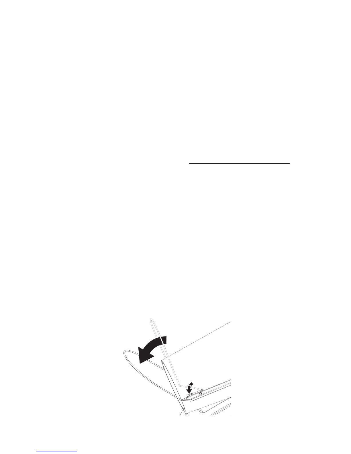
Figure 1 - Wire Guard moved to locked position
ASSEMBLY
WIRE GUARD
All Models
1. Grasp Wire Guard from top of shell and pull towards front of heater until it locks into
place in slots on both sides of upper shell.
www.usaprocom.com
160108-014
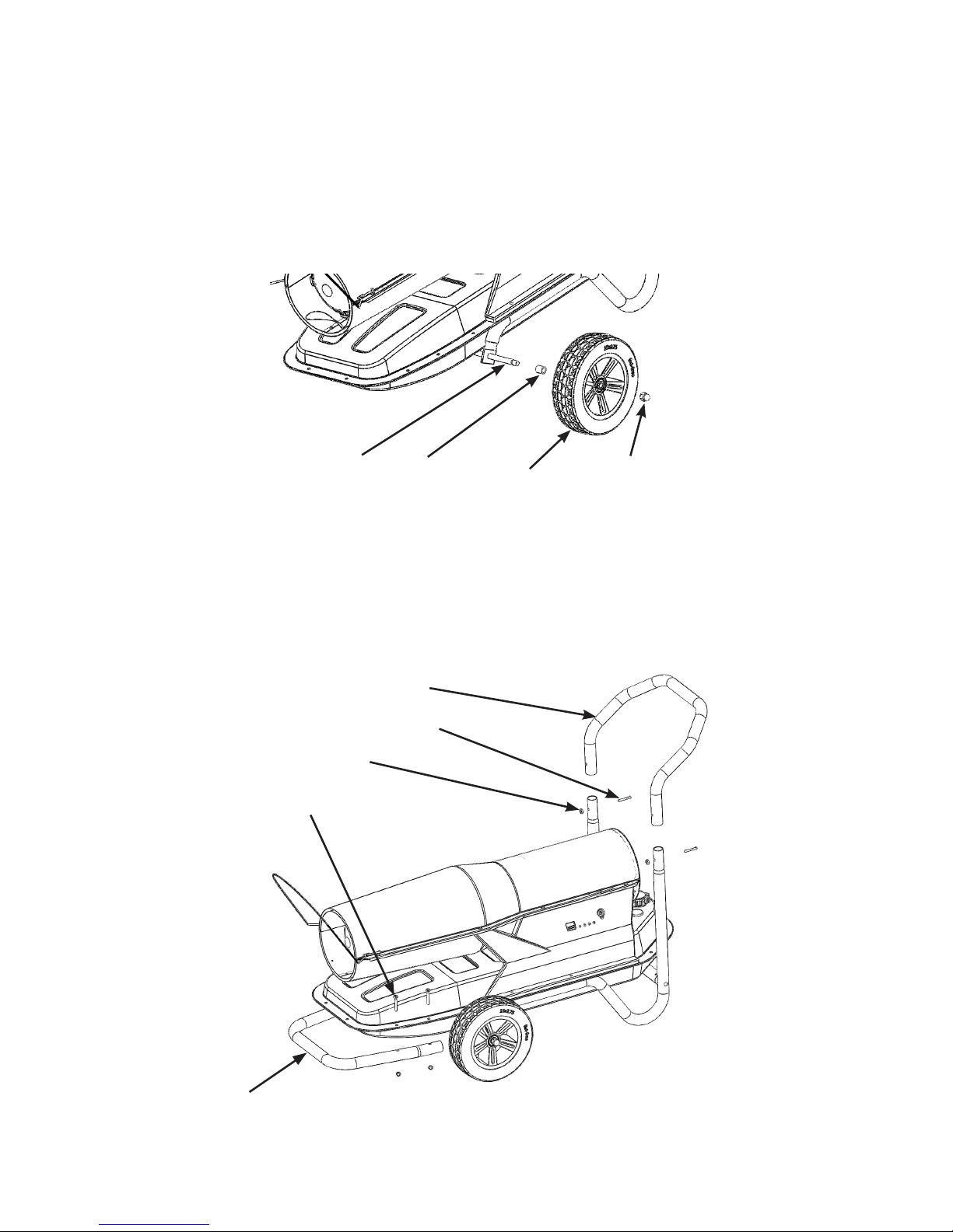
WHEEL ASSEMBLY
Models 160, 175 and 220
1. Slide Axle (A) through holes in wheel support frame.
2. Slide Wheel Spacer (B), then wheel (D) (concave side facing outward) onto axle.
3. Attach Acorn Nut (C) nger tight to end of axle.
4. Repeat steps 2 and 3 for opposite side, then tighten nuts with adjustable wrench.
Axle (A)
Acorn Nut (C)
Wheel (D)
Spacer (B)
Figure 2 - Wheel Assembly, 160, 175 and 220 models
HANDLE ASSEMBLY
Models 160, 175 and 220
1. Slide rear handle (E) onto Wheel Support Frame. Insert Screws (G) from rear and
attach lock nuts (F).
2. Place Front Handle (I) under ange of fuel tank and insert 4 screws (J)from top of
ange through holes in ange into holes in handle. Attach Lock Nuts (H) and tighten.
Rear Handle (E)
Screw, 10-24 x1.5 (G)
Lock Nut 10-24 (F)
Screw 1/4-20 x 1.75" (J)
Front Handle (I)
Figure 3 - Handle Assembly, 160, 175 and 220 models
ASSEMBLY
Continued
www.usaprocom.com
160108-01 5
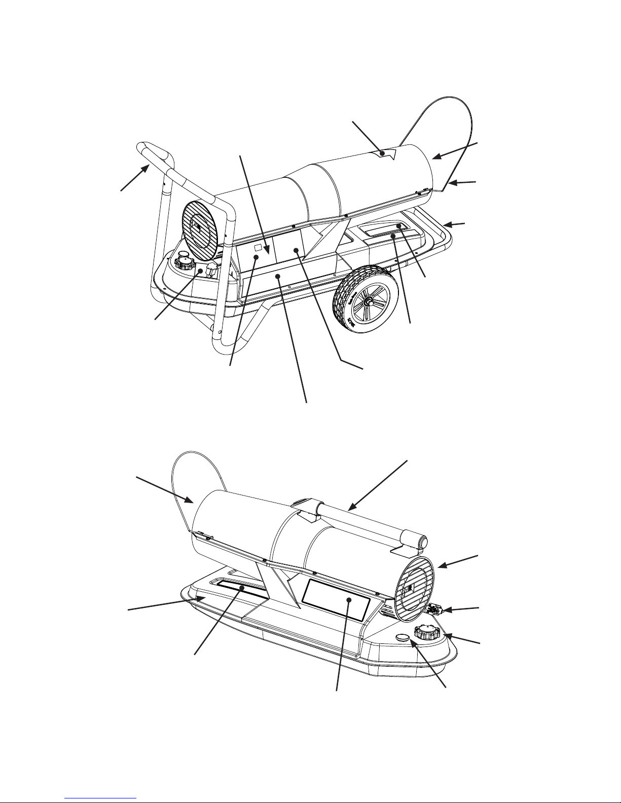
PRODUCT IDENTIFICATION & LABEL LOCATIONS
Fueling Label
Part No. 160168-01
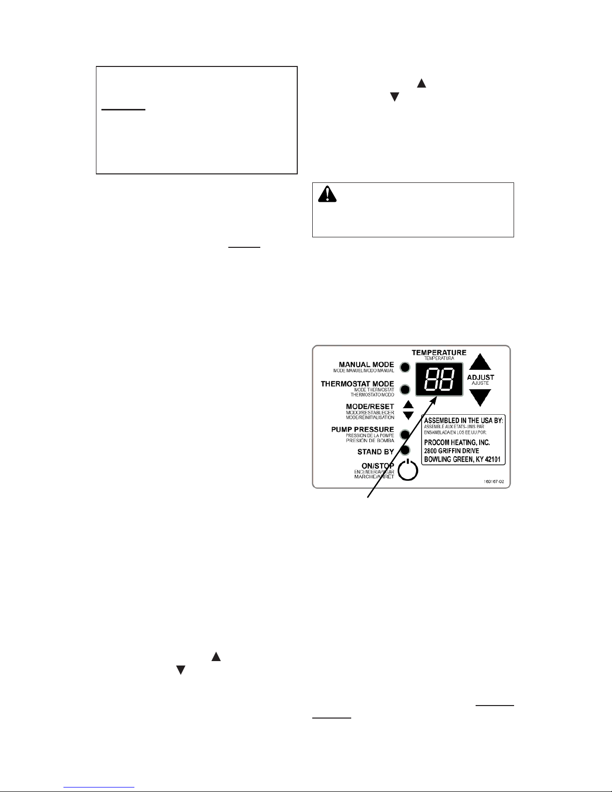
Control Label
Part No. 160167-02
CSA Label (Rating Plate)
Part No. 160111-04, 110 model
Part No. 160112-02, 160 model
Part No. 160112-03, 175 model
Part No. 160112-05, 220 model
Operating Label
Part No. 160173-01
Operating Codes Label
Part No. 160174-01
Maintenance Label
Part No. 160175-01
Caution Label
Part No. 160172-01
Figure 4 - Product Identication & Label Locations
Warnings Label
Part No. 160110-01
NY, MA and CA
Information Label
Part No. 160169-01
All Models
Right Side
(220 Model Shown)
All Models
Left Side
(110 Model Shown)
Front
Handle
(160, 175 &
220 models)
Hot Air
Outlet
Control
Panel
Rear
Handle
(160, 175 &
220 models)
Wire
Guard
Top Handle
(110 model)
Fuel
Tank
Cold Air
Inlet
Power
Cord
Fuel
Cap
Fuel
Gauge
Hot Air
Outlet
www.usaprocom.com
160108-016
SPECIFICATIONS
WARNING: Provide a fresh air
opening of at least three square
feet (2,800 square cm) for each
100,000 BTU/HR rating. Provide
extra fresh air if more heaters
are being used. The minimum
ventilation requirements must
be followed to avoid risks associated with carbon monoxide
poisoning. Make certain these
requirements are met prior to
operating heater.
Example: A 220,000 Btu/Hr (64.5 kw) heater
requires one of the following:
• a two-car garage door [16 feet (4.88 meter)
opening] raised 5" (12.7 cm)
• a single-car garage door [9 feet (2.74 meter) opening] raised 9" (22.9 cm)
• two, 30" (76.2 cm) windows raised 16"
(40.6 cm)
WARNING: Use only kerosene, #1/#2 diesel/fuel oil, JET
A or JP-8 fuels to avoid risk
of fire or explosion. Never
use gasoline, oil drained from
crankcases, naphtha, paint
thinners, alcohol or other highly
ammable fuels.
Use only kerosene, #1/#2 diesel*/fuel oil,
JET A, JP-8 fuels. Heavier fuels such as No.
2 fuel oil, No. 2 diesel fuel may also be used
but will result in:
• noticeable odor
• additional fuel lter maintenance
* Use of #2 diesel/fuel oil in extreme cold
temperatures may require nontoxic anti-icer
additives.
Do not use fuels heavier than No. 2 grade
or heavy oils such as oil drained from crankcases. These heavy oils will not ignite properly
and will contaminate the heater.
IMPORTANT: Use a KEROSENE ONLY (blue)
or DIESEL ONLY (yellow) storage container.
Be sure storage container is clean. Foreign
matter such as rust, dirt or water will cause the
ignition control assembly to shut down heater.
Foreign matter may also require heater's fuel
system to be frequently cleaned.
FUELS
VENTILATION
110 Model 160 Model 175 Model 220 Model
Output Rating
80K-110K 110K-160K 125K-175K 160K-220K
Fuel (all models)
Use only kerosene, #1/#2 diesel*/fuel oil, JET A or JP-8 fuels
Fuel Tank Capacity (gal/liter)
5.5 / 20.8 10 / 37.9 10 / 37.9 14 / 53
Fuel Consumption 0.82 / 3.1 1.19 / 4.5 1.3 / 4.9 1.64 / 6.2
(gal/liter per hr.)
Pump Pressure (PSI) 6.9 (hot) 6.7 (hot) 6.8 (hot) 8.4 (hot)
Electric Requirements
120 V/60 HZ 120 V/60 HZ 120 V/60 HZ 120 V/60 HZ
Amperage (Normal Run) 2.9 3.2 3.4 4.6
Typical Motor Speed (RPM)
3400 3400 3400 3400
Motor Horsepower 1/4 1/4 1/4 1/4
Shipping Weight (lbs / kg) 42 /19 71 /32.2 71 / 32.2 77 / 35
Heater Weight without 36 / 16.3 60.5 / 27.4 60.5 / 27.4 66 / 29.9
Fuel (approx) (lbs / kg)
www.usaprocom.com
160108-01 7
IMPORTANT: Review and understand the warnings in the
Safety section, pages 2 and 3.
They are needed to safely operate this heater. Follow all local
ordinances and codes when
using this heater.
TO START HEATER
1. Follow all ventilation and safety information.
2. Locate heater to provide maximum circulation of the heated air. Follow all location
requirements noted in Safety, pages
2 and 3.
3. Fill fuel tank with fuel and attach fuel cap.
Use only kerosene, #1/#2 diesel/fuel oil,
JET A or JP-8 fuels to avoid risk of re or
explosion. Never use gasoline, oil drained
from crank cases, naphtha, paint thinners,
alcohol or other ammable fuels.
4.
Plug heater’s power cord into approved,
grounded, three-wire extension cord. Extension cord must be at least six feet (1.8 m) long.
Extension Cord Size Requirement
• 6 to 10 feet (1.8 to 3 m) long, use 18
AWG (0.75 mm2) rated cord
• 11 to 100 feet (3.3 to 30.5 m) long, use
16 AWG (1.0 mm2) rated cord
• 101 to 200 feet (30.8 to 61 m) long, use
14 AWG (1.5 mm2) rated cord
5. Plug extension cord into standard 120
volt/60 hertz, 3-prong grounded outlet.
6.
Push ON/STOP button to ON. Alarm will sound
and display will start countdown to ignition. 6
seconds after motor startup, LED will display.
7. Push MODE/RESET button to select
desired operating mode.
Please Note: When operating in Ther-
mostat Mode, press the MODE/RESET
button once to change to Manual Mode.
When operating in Manual Mode, Press
the MODE/RESET button twice within 5
seconds to change to Thermostat Mode.
Manual Mode LED On: Adjust output to
disired setting. Press to raise the BTU
output. Press to lower the BTU output.
Please Note: After startup, heater BTU
output can be immediately adjusted, but
adjustments will not take effect for 2 minutes. This allows the heater to stabilize.
Thermostat Mode LED On: Adjust ther-
mostat by pressing to change set point
higher. Press to change set point lower.
If thermostat set temperature is higher
than the surrounding air temperature,
heater should ignite immediately. If heater
thermostat set temperature is lower than
surrounding air temperature, heater will
not ignite.
OPERATION
WARNING: This heater is
equipped with a thermostat.
Heater may start at any time.
TO STOP HEATER
1. Push ON/STOP button to stop heater.
2. Unplug heater when not in use.
TO RESET HEATER
1. Wait two minutes before restarting.
2.
Push MODE/RESET button to restart heater.
Fault Codes
This heater will display fault codes whenever
there is a control shutdown. See Trouble-
shooting, pages 9 - 12, before attempting to
rectify any problems with your heater.
LED display will show surrounding temperature
unless up and down arrow keys are pressed.
After pressing these keys, display shows set
point temperature for ve seconds and then will
change back to display surrounding temperature.
Exposure to direct sunlight or extreme cold may
affect temperature reading and/or thermostat
operation.
This thermostat will store the last set point
even if power is removed. Unit will maintain
this set point until a new set point is entered.
Figure 5 - Controls Display
www.usaprocom.com
160108-018
FUEL
F
Ground Wire (#10 AWG Stranded-Copper)
Copper
or Brass
Grounding
Point
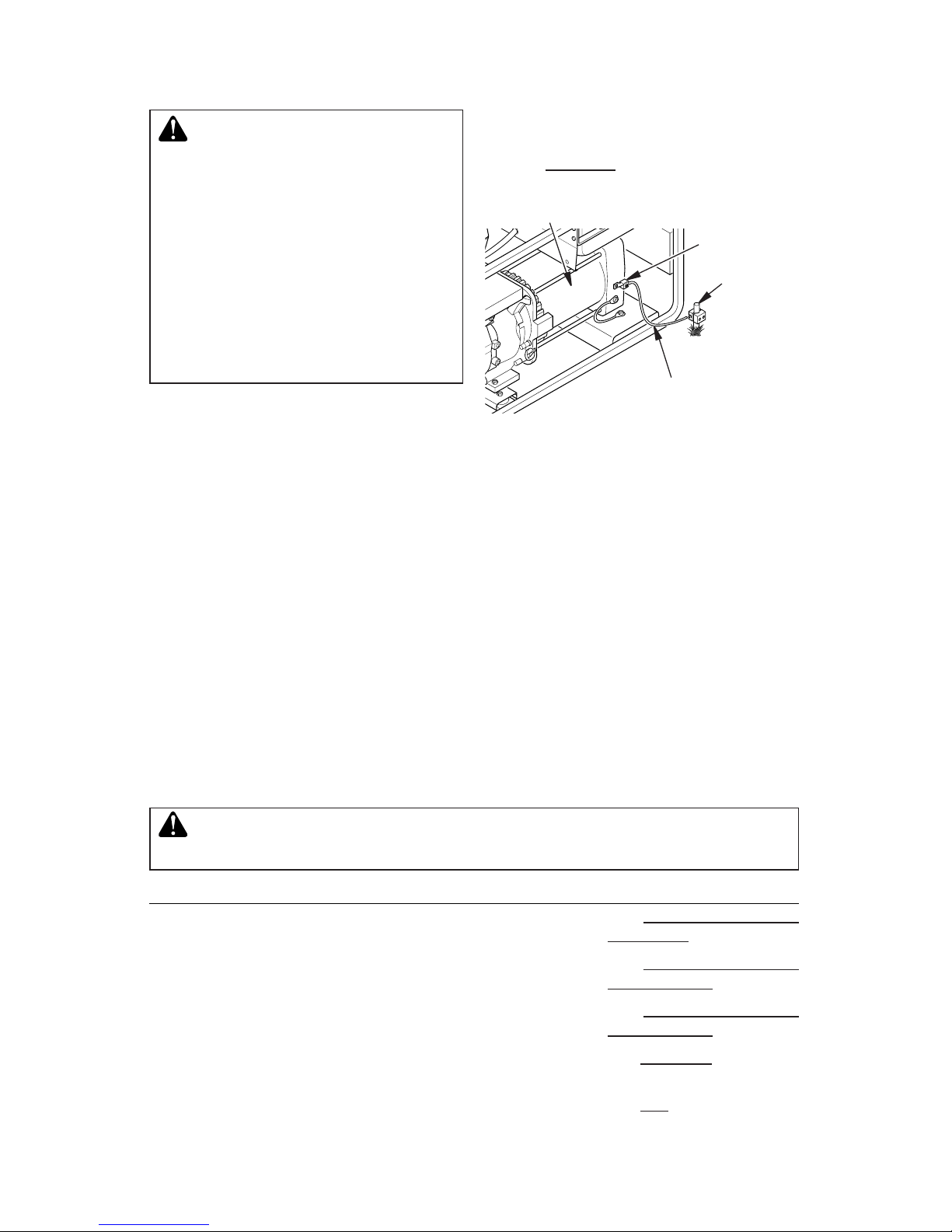
Figure 6 - Typical Generator Grounding
Method (Generator construction may
vary from that shown)
STORING, TRANSPORTING OR SHIPPING
WARNING: Never service heater while it is plugged in, operating
or hot. Severe burns and electrical shock can occur.
How To
See Storing, Transporting,
or Shipping, above
See Air Output, Air Intake
and Lint Filters, page 13
See Air Output, Air Intake
and Lint Filters, page 13
See Fuel Filter, page 14
See Fan, page 13
Item
Fuel tank
Air output and lint filters
Air intake filter
Fuel filter
Fan blades
Motor
How Often
Clean every season or as needed
Replace every 500 hours of operation
or once a year
Wash and dry with soap and water every
500 hours of operation or as needed
Clean twice a heating season or as
needed
Clean every season or as needed
Not required/permanently lubricated
OPERATION WITH PORTABLE GENERATOR
Alternator
Ground Lug
WARNING: Before operating
heater or any appliance from a
portable generator, verify that
generator has been properly connected to earth ground. Improper
grounding or failure to ground
generator can result in electrocution if a ground fault occurs.
Refer to owner’s manual supplied
by generator manufacturer for
proper grounding procedures.
Operating voltage range of heater is 95 to 135
Volts. Prior to plugging heater into generator
output voltage should be veried (if generator
is equipped with automatic idle feature, output
voltage should be measured with generator
running at full speed). If voltage does not
measure in this range heater should not be
plugged into generator.
Refer to Operation, page 7, for starting, stopping and resetting heater procedures.
Note: If shipping, transport companies require
fuel tanks to be empty.
1. Remove excess fuel from tank using a siphon pump. Drain remaining fuel through
ller neck by tipping heater to the rear.
2. If any debris is noted in old fuel, add 1 or 2
quarts of clean kerosene to tank, stir and
drain again. This will prevent excess debris
from clogging lters during future use.
3. Properly dispose of old and dirty fuel.
Check with local automotive service stations that recycle oil.
4. If storing, store heater in dry place. Make
sure storage place is free of dust and
corrosive fumes.
IMPORTANT: Do not store kerosene over
summer months for use during next heating
season. Using old fuel could damage heater.
PREVENTATIVE MAINTENANCE SCHEDULE
www.usaprocom.com
160108-01 9
TROUBLESHOOTING
WARNING: Never service heater while it is plugged in, operating
or hot. Severe burns and electrical shock can occur.
POSSIBLE CAUSE
1. Control remembers Codes
from prior operation
1. No power to heater (All
LED's are off)
2. Bad electrical connection
between control and power
cord
1. Thermostat setting is too
low.
1. Supply voltage is above
135 volts
Generator out of regulation
1. Supply voltage is below 95
volts. Poor supply circuit or
extension cord too long or
inadequate gauge.
1. Room or ambient temperature exceeds 100°F
1. Bad electrical connection
between motor and power
cord.
2. Motor locked-fan obstructed
3.
Motor locked-pump obstructed
4. Motor defective
REMEDY
1. Press MODE/RESET button
to clear Code and restart
heater.
1. Check power cord connections.
2. Unplug heater. Check all
electrical connections. (see
wiring diagram, page 18)
1. Adjust thermostat to a higher setting by pressing
button or change to MAN-
UAL MODE by pressing the
MODE/RESET button
1. Conrm supply voltage is
below 135 volts.
1. Conrm supply voltage is
above 95 volts. See extension cord requirements on
page 7.
1. Operate heater in a cooler
environment.
1. Unplug heater. Check all
electrical connections. (See
wiring diagram, page 18)
2. Unplug heater. Clear fan
obstruction.
3. Service pump (See page
17)
4. Unplug heater. Replace
motor.
DISPLAY
Display shows
C1,C2,C3,C4,C5,C6,
C7,C8 or C9
Display is Off
Display shows room
temperature
Display shows C1 High
Voltage
Display shows C2 Low
Voltage
Display shows C8 Temperature over 100°F
Display shows C9 Low
Pressure
WARNING: High voltage!
Unplug heater before servicing.
FAULT CONDITION
Motor does not start after heater is
plugged in and ON/STOP button is ON.
www.usaprocom.com
160108-0110
POSSIBLE CAUSE
1. Air line or tting leaking.
2. Pump cover leaking
Pump cover screws loose
3. Pump cover gasket leaking
Pump output lter clogged
4. Pump pressure is low
5. Pump pressure is low. Can-
not adjust to specication
1. No fuel in fuel tank
2. Water in fuel tank
3. Pump pressure incorrect
4. Dirty Fuel Filter
5. Obstruction in Nozzle
6. Bad electrical connection
between ignitor and control
7. Blown control fuse
8. Defective ignitor
9. Defective ignition control
assembly
REMEDY
1. Unplug heater. Check air
lines and ttings for leaks.
Correct all leaks.
2. Unplug heater.Check pump
cover for leaks. Tighten
pump cover screws to 1020 in-lbs.
3.
Unplug heater. Replace pump
output lter. See Pump Pressure Adjustment page 14.
4.
Adjust pump pressure to
specication. See Pump Pressure Adjustment, page 14.
5. Service pump, see page 17.
1. Fill Tank. See Fuels, page
6. Restart heater.
2. Drain and ush fuel tank
with kerosene. See Storing,
Transporting or Shipping,
page 8.
3. See Pump Pressure Adjust-
ment, page 14.
4. See Fuel Filter, page 14.
5. See Nozzle Assembly,
page 16.
6.
Check electrical connections.
See Wiring Diagram, page 18.
7. Replace control fuse, see
page 17.
8. Replace ignitor and control
fuse, see pages 14 & 17.
9. Replace ignition control
assembly
DISPLAY
Display shows C9 Low
Pressure
Display shows C3 No
Ignition
TROUBLESHOOTING
Continued
FAULT CONDITION
Motor starts and runs but heater does
not ignite.
WARNING: High voltage!
Unplug heater before servicing.

www.usaprocom.com
160108-01 11
POSSIBLE CAUSE
1. Not enough fuel in tank to
maintain combustion
2. Water in fuel tank
3. Pump pressure incorrect
4. Dirty fuel lter
5. Obstruction in nozzle
6. Photocell assembly not
properly installed
7. Dirty photocell lens
8. Defective photocell
1. Pump pressure too high
2. Heater inlet or outlet is covered and unit is not getting
enough air for combustion
3. Fan set screw is loose
1. Heater inlet suddenly
blocked by debris.
2. Water in fuel tank
3. Dirty fuel lter
4. Obstruction in nozzle
5. Fan set screw is loose
REMEDY
1. Fill tank. See Fuels, page 6.
Restart heater.
2. Drain and ush fuel tank
with kerosene. See Storing,
Transporting or Shipping,
page 8.
3. See Pump Pressure Adjustment, page 14.
4. See Fuel Filter, page 14.
5. See Nozzle Assembly,
page 16.
6. Make sure photocell boot is
fully seated in bracket.
7. Clean photocell lens.
8. Replace photocell.
1. See Pump Pressure Adjustment, page 14.
2. Unplug heater. Remove obstructions or loose material
from heater inlet or outlet.
3. Tighten fan set screw to
40-50 in-lbs. See service
procedures on page 13.
1. Unplug heater. Remove obstructions or loose material
from heater inlet.
2. Drain and ush fuel tank
with kerosene. See Storing,
Transporting or Shipping,
page 8.
3. See Fuel Filter, page 14.
4. See Nozzle Assembly,
page 16.
5. Tighten fan set screw to
40-50 in-lbs. See service
procedures on page 13.
DISPLAY
Display shows C4 Flame
Extinguished
Display shows C5 Improper
Flame
Display shows C6 Flame
Change
TROUBLESHOOTING
Continued
FAULT CONDITION
Heater ignites but control assembly shuts
heater off before running out of fuel.
WARNING: High voltage!
Unplug heater before servicing.

www.usaprocom.com
160108-0112
REMEDY
1. Unplug heater. Depress
and release each control
button several times to
check operation. Every button should click every time
it is depressed.
2. Replace control assembly.
1. Operate heater in a cooler
environment.
1. Unplug heater. Check air
lines and ttings of leaks.
Correct all leaks.
2. Unplug heater. Check pump
cover for leaks. Tighten
pump cover screws to 1020 in-lbs.
3. Unplug heater Replace
pump output filter. See
Pump Maintenance, page
17.
4. Adjust pump pressure to
specification. See Pump
Pressure Adjustment, page
14.
5. Replace pump lters. See
page 13.
6. Adjust pump rotor gap or
replace pump rotor and
blades. See page 17.
POSSIBLE CAUSE
1. One or more of the control
buttons is depressed continuously (stuck).
2. Defective control assembly
1. Room or ambient temperature exceeds 100°F
1. Air line or tting leaking
2. Pump cover leaking. Pump
cover screws loose
3. Pump cover gasket leaking.
Pump output lter clogged
4. Pump pressure is low
5. Pump pressure is low. Can-
not adjust to specication.
Pump lters are dirty.
6. Pump pressure is low, pump
has excessive wear or improper adjustment
DISPLAY
Display shows C7 Control
Button Stuck
Display shows C8 Temperature Over 100°F
Display shows C9 Low Pres-
sure (Setting 5)
TROUBLESHOOTING
Continued
FAULT CONDITION
(Continued) Heater ignites but control
assembly shuts heater off before running out of fuel.
WARNING: High voltage!
Unplug heater before servicing.

www.usaprocom.com
160108-01 13
Figure 7 - Upper Shell Removal,
Motor
Shaft
Setscrew
Figure 8 - Fan, Motor Shaft, and
Setscrew Location
Motor
Shaft
Back of Flat on
Motor Shaft
1.82"
Motor
Shaft
Length
Fan
Setscrew
Touching
Back of
Flat on
Motor
Shaft
Figure 9 - Fan Cross Section
Fan
Motor
SERVICE PROCEDURES
WARNING: To avoid risk of
burn and electrical shock, never
attempt to service heater while it
is plugged in, operating, or hot.
UPPER SHELL REMOVAL
1. Remove screws along each side of heater
using 5/16" nut-driver. These screws attach upper and lower shells together. See
Figure 7.
2. Lift upper shell off.
3. Remove fan guard.
FAN
IMPORTANT: Remove fan from motor shaft
before removing motor from heater. The
weight of the motor resting on the fan could
damage the fan pitch (see Figure 8).
1.
Remove upper shell (see Figure 7).
2. The fan is located with the set screw in
contact with the back of at on motor as
shown in Figure 9.
3. Use 1/8" allen wrench to loosen setscrew
which holds fan to motor shaft (see Figure
8).
4. Slip fan off motor shaft.
5. Clean fan using a soft cloth moistened
with kerosene or solvent.
6. Dry fan thoroughly.
7. Place setscrew on flat of shaft.
Tighten setscrew firmly (40-50 inchpounds/4.5-5.6 n-m).
8. Replace fan guard and upper shell.
AIR OUTPUT, AIR INTAKE
AND LINT FILTERS
1.
Remove upper shell (see Figure 7).
2. Remove lter end cover screws using
5/16" nut-driver (see Figure 10).
3. Remove lter end cover.
4. Replace air output and lint lters.
5. Wash or replace air intake lter.
6. Replace lter end cover.
7. Replace fan guard and upper shell.
IMPORTANT: Do not oil lters.
Air Intake
Filter
Lint Filter
Filter
End
Cover
Air Output
Filter
Figure 10 - Air Output, Air Intake, and
Lint Filters

www.usaprocom.com
160108-0114
SERVICE PROCEDURES
Continued
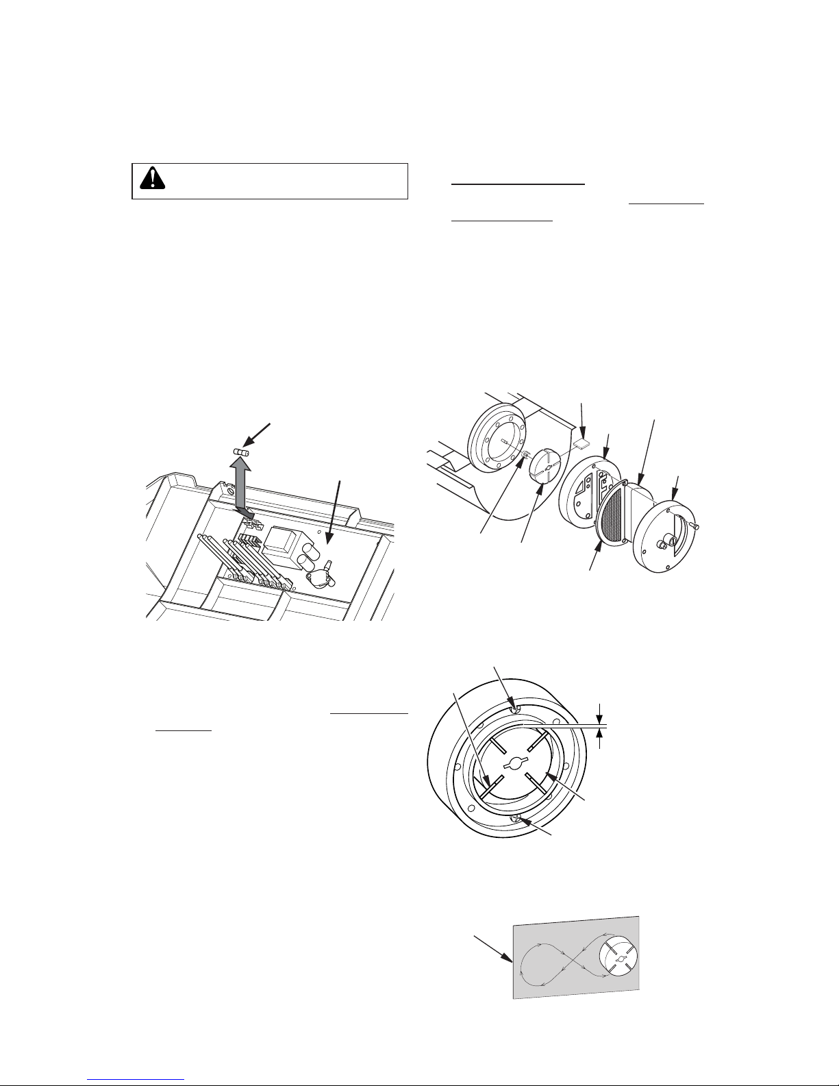
PUMP PRESSURE
ADJUSTMENT
1. Remove pressure gauge plug from lter
end cover (see Figure 11).
2. Install 0-15 PSI pressure gauge.
3. Start heater (see Operation, page 7). Allow heater to reach operating temperature
(approx. 10 minutes).
4. Set heater to MANUAL MODE, SETTING
5. This is the only setting that will allow
pressure adjustment.
5. Adjust pressure. Turn relief valve to right
to increase pressure. Turn relief valve to
left to decrease pressure. See specications with Figure 12 for correct pressure
for each model.
6. Remove pressure gauge. Replace pres-
sure gauge plug in lter end cover.
7. This heater continuously monitors pump
pressure with a built-in pressure sensor.
To display the pump pressure while oper-
ating, set the heater to MANUAL MODE,
SETTING 5, then press the MODE/RESET button once. Pump pressure will be
displayed (example: "6.9") for 5 seconds.
Figure 11 - Pressure Gauge Plug
Removal
Pressure
Gauge
Plug
Pressure
Gauge
Figure 12 - Adjusting Pump Pressure
Relief
Valve
Pump
Model Pressure
110 6.9 PSI
160 6.7 PSI
175 6.8 PSI
220 8.4 PSI
Fuel Filter,
Bushing, and
Lower Fuel Line
Upper Fuel
Line
Side
Cover
Figure 13 - Fuel Filter Removal
IGNITOR
1. Remove upper shell and fan guard (See
Upper Shell Removal, page 13).
2. Remove fan (see page 13).
3. Remove the control side cover with a
5/16" nut driver. On 160, 175 and 220
models, remove two wheel support bolts
and nuts with a Phillips screwdriver and
an adjustable wrench. Remove side cover
(see Figures 13).
FUEL FILTER
1. Remove side cover screws using 5/16"
nut-driver.
2. Remove side cover with a 5/16" nut driver.
On 160, 175 and 220 models, remove
two wheel support bolts and nuts with
a Phillips screwdriver and an adjustable
wrench..
3. Pull upper fuel line off fuel lter neck (see
Figure 13).
4. Carefully pry bushing, fuel filter, and
lower fuel line out of fuel tank (see Figure
13).
5. Wash fuel lter with clean fuel and replace
in tank.
6. Attach upper fuel line to fuel lter neck.
7. Replace side cover.
www.usaprocom.com
160108-01 15
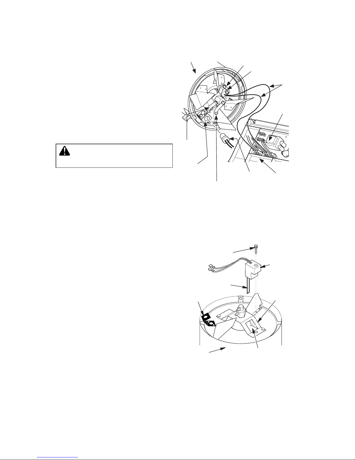
4. Disconnect ignitor wires from ignition
control assembly (see Figure 14). Pull
the ignitor wires up through the hole in
the lower shell.
5. Disconnect fuel line hose and air line
hose. Remove photocell from photocell
bracket (see Figure 14).
6. Remove combustion chamber. Stand combustion chamber on end with nozzle adapter
bracket on top (see Figure 15).
7. Remove ignitor screw with a 1/4" nut
driver. Carefully remove ignitor from
nozzle adapter bracket.
CAUTION: Do not bend or strike
ignitor element. Handle with care.
8. Carefully remove replacement ignitor from
packing.
9. Carefully guide ignitor into opening in
nozzle adapter bracket. Do not strike
ignitor element. Attach ignitor to nozzle
adapter bracket with screw using a 1/4"
nut driver. Torque 0.90 to 1.69 N-m (8 to
15 in-lbs) Do not over torque.
10. Replace combustion chamber.
11. Route the ignitor wires back down through
the hole in the lower shell. Connect wires
to the ignition control assembly (see Figure 14).
12. Replace fuse on ignition control assembly
with the fuse provided with the SP002-01
Igniter Kit. See Ignition Control Assembly,
page 17.
13. Replace control side cover.
14. Connect and route fuel line hose and air
line hose to nozzle adapter assembly.
15. Replace photocell in photocell bracket.
16. Replace fan (see page 13).
17. Replace fan guard and upper shell (see
page 13).
SERVICE PROCEDURES
Continued
Photocell
Bracket
Ignitor
Ignitor Screw/
Washer Assembly
Nozzle
Adapter
Bracket
Ignitor
Element
Combustion
Chamber
Nozzle Adapter
Bracket Opening
Figure 15 - Ignitor SP002-01
Replacement
Figure 14 - Disconnecting Ignitor Wires
from Ignition Control Assembly
Photocell
Bracket
Air Line
Hose
Fuel Line
Hose
Combustion
Chamber
Photocell
Assembly
Ignitor
Nozzle Adapter
Bracket
Ignition
Control
Assembly
Side
Cover
Ignitor
Wire
www.usaprocom.com
160108-0116
SERVICE PROCEDURES
Continued
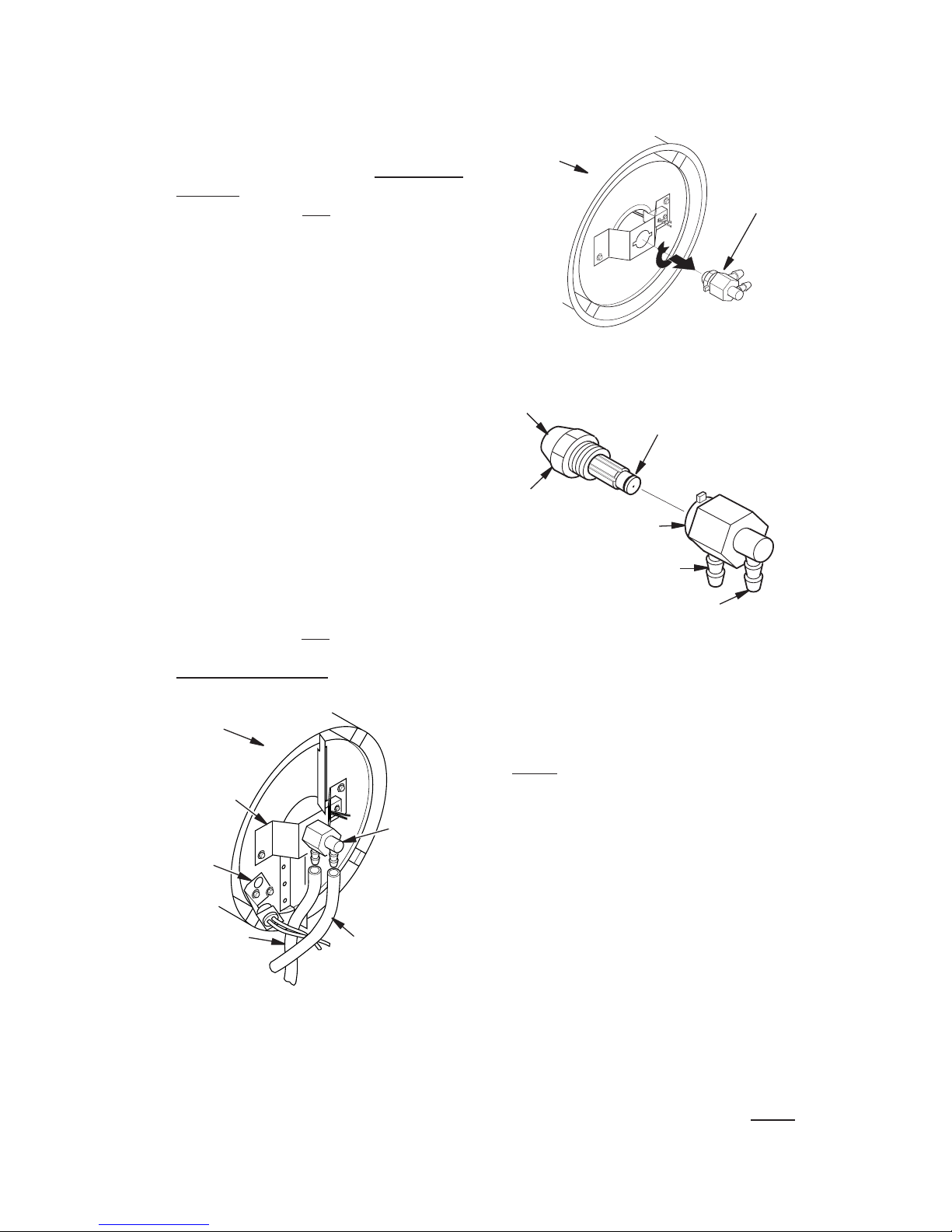
Figure 16 - Removing Air and Fuel Line
Hoses
Fuel Line
Hose
Air Line
Hose
Nozzle/
Adapter
Assembly
Combustion
Chamber
Photocell
Bracket
Nozzle
Adapter
Bracket
NOZZLE ASSEMBLY
1. Remove upper shell (see Upper Shell
Removal, page 13).
2. Remove fan (see Fan, page 13).
3. Remove fuel and air line hoses from
nozzle assembly (see Figure 16).
4. Turn nozzle assembly 1/4 turn to left
and pull toward motor to remove (see
Figure 17).
5. Place plastic hex-body into vise and lightly
tighten.
6. Carefully remove nozzle from the nozzle
adapter using 5/8" socket wrench (see
Figure 18).
7. Blow compressed air through face of nozzle.
This will free any dirt in nozzle area.
8. Inspect nozzle sleeve for damage.
9. Replace nozzle into nozzle adapter until
nozzle seats. Tighten 1/3 turn more using
5/8" socket wrench 4.5 to 5.1 N-m (40 to
45 in-lbs). See Figure 18.
10. Attach nozzle assembly to burner strap
(see Figure 17).
11. Attach fuel and airline hoses to nozzle
assembly.
12. Replace fan (see Fan, page 13).
13. Replace fan guard and upper shell (see
Upper Shell Removal, page 13).
Figure 17 - Removing Nozzle/Adapter
Assembly
Nozzle/
Adapter
Assembly
Combustion
Chamber
Figure 18 - Nozzle and Nozzle Adapter
Nozzle Face
Nozzle
Nozzle Sleeve
Nozzle
Adapter
Air Line
Fitting
Fuel Line
Fitting
(For 220 Model Only)
1. Remove combustion chamber and ignitor
by following steps 1 through 7 under
Ignitor, page 14.
2. Carefully place ignitor in a safe location.
3. Remove two nozzle adapter bracket
screws.
4. Place hex-shaped aluminum nozzle
adapter into vise (do not overtighten).
5. Carefully remove nozzle from nozzle
adapter using 5/8" socket wrench (see
Figure 18).
6. Blow compressed air through face of
nozzle. This will remove any debris in
nozzle.
7. Inspect nozzle seal for damage.
8. Replace nozzle into nozzle adapter until
nozzle seats. Tighten 80-110 inch-pounds.
9. Attach nozzle adapter bracket to combustion chamber with two screws removed in
step 3.
10. Repeat steps 9 through 16 under Ignitor,
page 14.
www.usaprocom.com
160108-01 17
SERVICE PROCEDURES
Continued
IGNITION CONTROL
ASSEMBLY
WARNING: High voltage!
1. Unplug heater.
2. To expose the ignition control assembly,
remove the control panel side cover
screws using 5/16" nut-driver. On 160,
175 and 220 models, remove two wheel
support bolts and nuts with a Phillips
screwdriver and an adjustable wrench.
3.
Remove fuse from fuse clips (see Figure 19).
4. Replace fuse with fuse of the same type
and rating (7A, 125VP). Do not substitute
a fuse with a higher current rating.
5. Replace control panel side cover.
Figure 19 - Replacing Fuse
Ignition
Control
Assembly
Fuse
PUMP ROTOR
(Procedure if Rotor is Binding)
1. Remove upper shell (see Upper Shell
Removal, page 13).
2. Remove filter end cover screws using
5/16" nut driver (see Figure 20).
3. Remove filter end cover and air filters.
4. Remove pump plate screws using 5/16"
nut-driver.
5. Remove pump plate.
6. Remove rotor, insert, and blades (see
Figure 21).
7. Check for debris in pump. If debris is
found, blow out with compressed air.
8. Install insert and rotor.
9.
Check gap on rotor. Adjust to 0.076/0.101 mm
(0.003"/0.004") if needed (see Figure 21).
Note: Rotate rotor one full turn to ensure
the gap is 0.076/0.101 mm (0.003"/0.004")
at tightest position. Adjust if needed.
Figure 20 - Rotor Location
Pump
Plate
Insert
Rotor
Blade
Filter
End
Cover
Air
Intake
Filter
Air Output Filter
Gap Adjusting
Screw
Rotor
Blade
0.003"/0.004"
(0.076-0.101
mm) Gap
Measured With
Feeler Gauge
Gap Adjusting Screw
Figure 21 - Gap Adjusting Screw
Locations
Sandpaper
Figure 22 - Sanding Rotor
10. Install blades, pump plate, air filters, and
filter end cover.
11. Replace fan guard and upper shell (see
Upper Shell Removal, page 13).
12. Adjust pump pressure (see Pump Pres-
sure Adjustment, page 14).
Note: If rotor is still binding, proceed as
follows.
13. Perform steps 1 through 6.
14. Place fine grade sandpaper (600 grit) on
flat surface. Sand rotor lightly in “figure 8”
motion four times (see Figure 22).
15. Reinstall insert and rotor.
16. Perform steps 10 through 12.
www.usaprocom.com
160108-0118
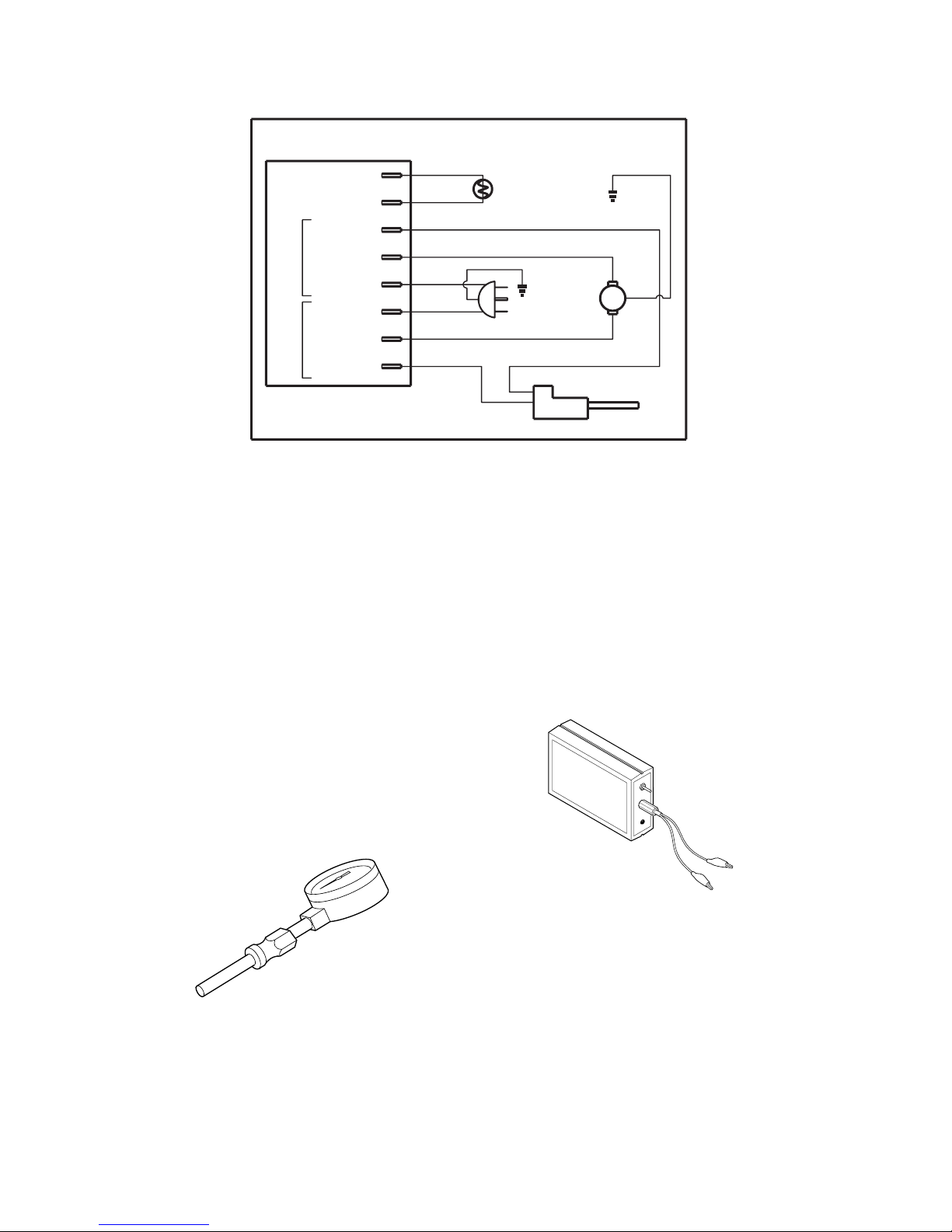
WIRING DIAGRAM
AIR GAUGE KIT
For all models. Special tool to check pump
pressure. 0-15 PSI gauge. 3/8" NPT pipe
thread.
IGNITION CONTROL
ASSEMBLY/PHOTOCELL
TESTER
Special tool used to test the ignition control
assembly and photocell.
Purchase these accessories from your
local dealer. If they can not supply these
accessories, contact ProCom Heating, Inc.
at 1-877-886-5989 for information. You can
also write to the address listed on the back
page of this manual.
ACCESSORIES
You may have further questions about installation, operation, or troubleshooting. If so,
contact ProCom Heating, Inc. at 1-877-886-
5989. When calling please have your model
and serial numbers of your heater ready.
TECHNICAL SERVICE
You can also visit ProCom Heating, Inc.’s web
site at www.usaprocom.com.
Blue
main return
Heater Control Assmebly
Blue
White
White
Black
Ignitor
Red
Photocell
Photocell
Photocell
Ignitor IGN
Motor MTR
Neutral AC
Line (L1) AC
Motor MTR
Ignitor IGN
Ground
Ground
Green
Green
motor
Yellow or White
Yellow or
White
Power Plug
120V/60Hz
www.usaprocom.com
160108-01 19
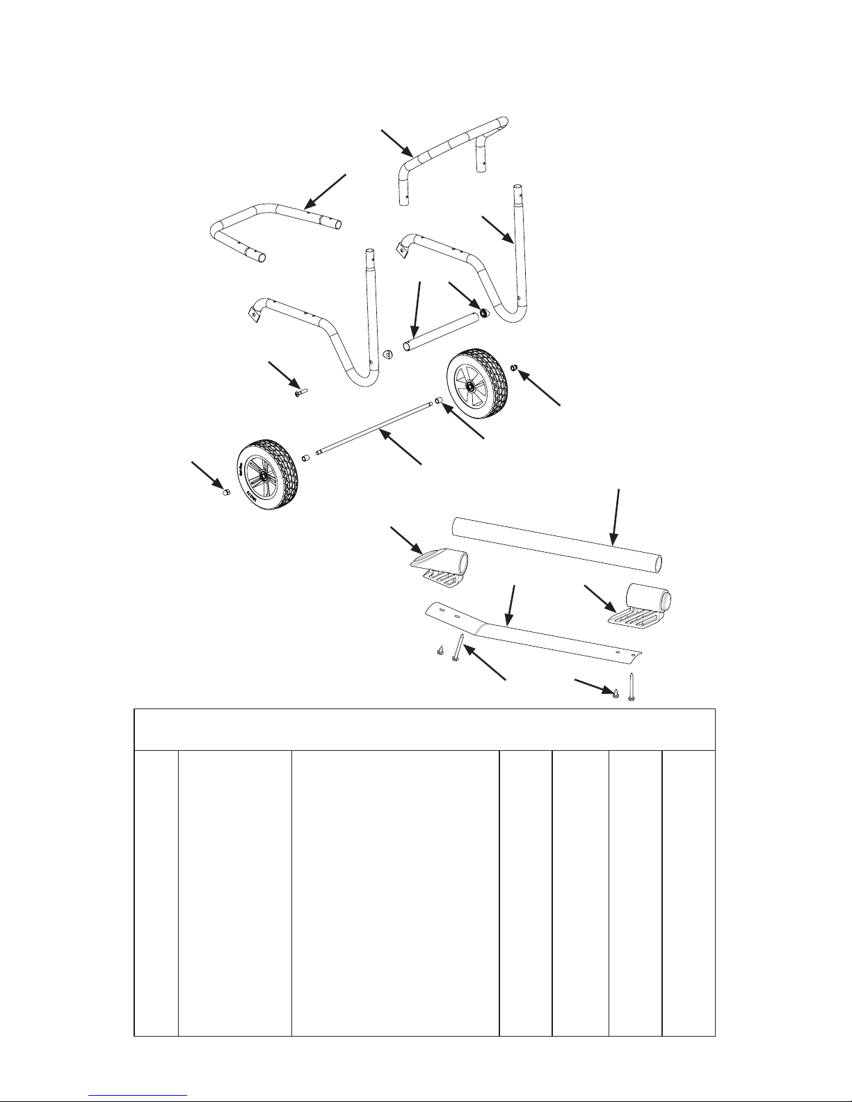
PARTS
WHEEL AND HANDLES
2
1
4
11
14
6
16
7
12
13
10
9
8
15
3
5
KEY QTY QTY QTY QTY
NO. PART NO. DESCRIPTION 110 160 175 220
1 160074-01 Rear Handle 1 1 1
2 160073-01 Front Handle 1 1 1
3 160072-01 Wheel Support Frame 2 2 2
4 160158-01 Support Bushing 2 2 2
5 160072-12 Fuel Tank Support Assembly 1 1 1
6 160072-13 Screw, M10-1.5 x 60 2 2 2
7 160129-01 Acorn Nut 2 2 2
8 160080-01 Wheel 2 2 2
9 160130-01 Wheel Spacer 2 2 2
10 160079-01 Axle 1 1 1
11 160062-01 Handle 1
12 160064-01 Front Handle Bracket 1
13 160064-02 Rear Handle Bracket 1
14 160083-01 Shell Heat Shield 1
15 160100-01 Screw, 10-16 x 2.0 1
16 160078-01 Screw, 10-16 x .5 1
160, 175, and
220 Models
110 Model
www.usaprocom.com
160108-0120
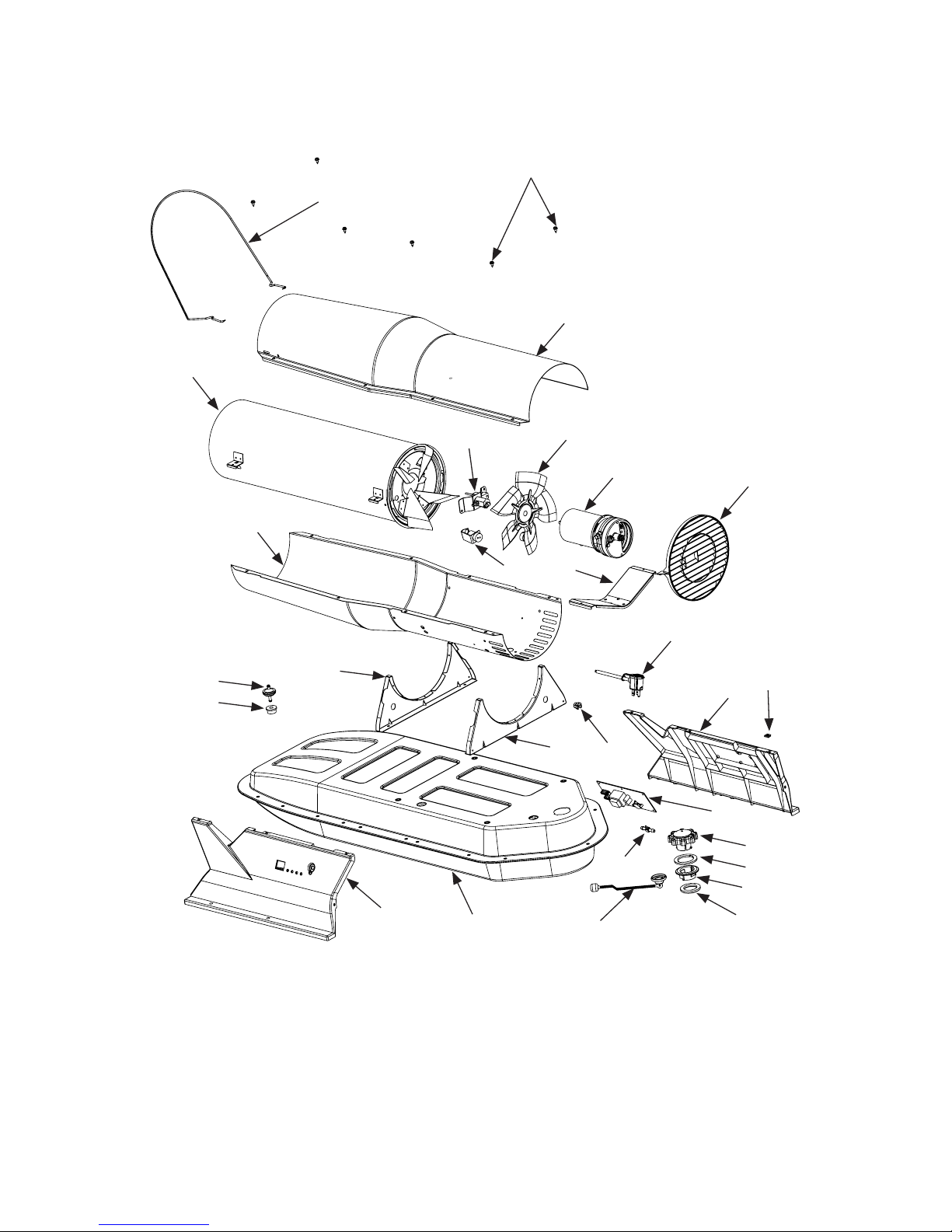
PARTS
1
2
3
4
6
7
8
10
11
5
9
15
17
18
16
14
14
12
13
19
20
21
22
23
24
25
26
27

www.usaprocom.com
160108-01 21
KEY QTY QTY QTY QTY
NO. PART NO. DESCRIPTION 110 160 175 220
1 160075-01 Guard Wire 1
1 160075-02 Guard Wire 1 1
1 160075-03 Guard Wire 1
2 160101-01 Shell Screw 8 8 8 8
3 160050-01GY Upper Shell, Painted 1
3 160144-01GY Upper Shell, Painted 1 1
3 160147-01GY Upper Shell, Painted 1
4 160135-01 Combustion Chamber Assy. 1
4 160136-01 Combustion Chamber Assy. 1
4 160137-01 Combustion Chamber Assy. 1
4 160138-01 Combustion Chamber Assy. 1
5 160051-01GY Lower Shell, Painted 1
5 160145-01GY Lower Shell, Painted 1 1
5 160148-01GY Lower Shell, Painted 1
6
see detail, pg 23
Nozzle Bracket Assembly
7 160011-01 Fan 1
7 160058-01 Fan 1 1 1
8
see detail, pg 22
Motor/Pump Assembly
9
see detail, pg 22
Photocell/Bracket Assembly
10 160043-01 Motor Mounting Bracket 1
10 160043-02 Motor Mounting Bracket 1 1 1
11 160066-01 Fan Guard 1
11 160066-02 Fan Guard 1 1 1
12 160012-02 Fuel Filter 1
12 160012-01 Fuel Filter 1 1 1
13 160034-01 Fuel Tube Bushing 1 1 1 1
14 160060-01 Small Shell Bracket 2
14 160060-02 Large Shell Bracket 2 2 2
15 160020-03 Power Supply Cord 1 1 1 1
16 160013-01 Strain Relief Bushing 1 1 1 1
17 160056-01 Right Side Cover 1
17 160056-02 Right Side Cover 1 1 1
18 160087-01 Clip, Nut, #10, .08 Wall 6 6 6 6
19 160055-01 Left Side Cover 1
19 160055-02 Left Side Cover 1 1 1
20 160139-01GY Fuel Tank Assy., Small 1
20 160140-01GY Fuel Tank Assy., Medium 1 1
20 160141-01GY Fuel Tank Assy., Large 1
21 160005-01 Fuel Gauge 1
21 160005-02 Fuel Gauge 1 1 1
22 160037-04 Nylon Airline Tee 1 1 1 1
23 160171-01 Programmed Variable Control 1
23 160171-02 Programmed Variable Control 1 1
23 160171-03 Programmed Variable Control 1
24 160030-01 Vented Fuel Cap Assy. 1 1 1 1
25 160030-03 Vented Fuel Cap Gasket 1 1 1 1
26 160031-01 Plastic Filler Neck 1 1 1 1
27 160036-01 Filler Neck Gasket 1 1 1 1
Parts Available - Not Shown
160037-02 Airline Tubing 2 2 2 2
160039-01 Upper Fuel Line 1 1 1 1
160038-01 Lower Fuel Line 1
160038-02 Lower Fuel Line 1 1 1
160037-03 Control Airline 1 1 1 1
PARTS
This list contains replaceable parts used in your heater. When ordering parts, be sure to provide correct model and serial numbers (from model plate), and part number and description of desired part.
www.usaprocom.com
160108-0122
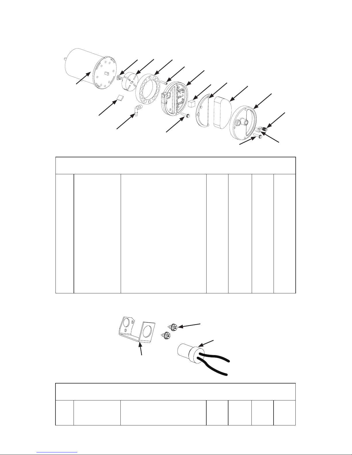
PHOTOCELL ASSEMBLY
1
2
3
KEY QTY QTY QTY QTY
NO. PART NO. DESCRIPTION 110 160 175 220
1 160041-03 Photocell Bracket 1 1 1 1
2 160092-02 Screw, 6-32 x .38 2 2 2 2
3 160016-01 Photocell Assembly 1 1 1 1
KEY QTY QTY QTY QTY
NO. PART NO. DESCRIPTION 110 160 175 220
1 160001-01 Motor 1 1 1 1
2 160023-01 Rotor Insert 1 1 1 1
3 160003-01 Pump Rotor 1 1 1 1
4 160006-01 Pump Body 1 1 1 1
5 160088-01 Screw, 10-32 x .62 2 2 2 2
6 160007-01 Pump Cover 1 1 1 1
7 160009-01 Lint Filter 1 1 1 1
8 160008-01 Output Filter Assembly 1 1 1 1
9 160010-01 Intake Filter 1 1 1 1
10 160057-01 Filter End Cover 1 1 1 1
11 160106-01 Adjusting Screw 1 1 1 1
12 160024-01 Pipe Plug 1 1 1 1
13 160090-01 Screw, 10-32 x 1.0 3 3 3 3
14 160089-01 Screw, 10-32 x 1.12 6 6 6 6
15 160029-01 90° Nylon Elbow 1 1 1 1
16 160004-01 Pump Blade 4 4 4 4
PARTS
MOTOR AND PUMP ASSEMBLY
1
2
3
4
5
6
7
8
9
10
11
12
13
15
14
16
www.usaprocom.com
160108-01 23
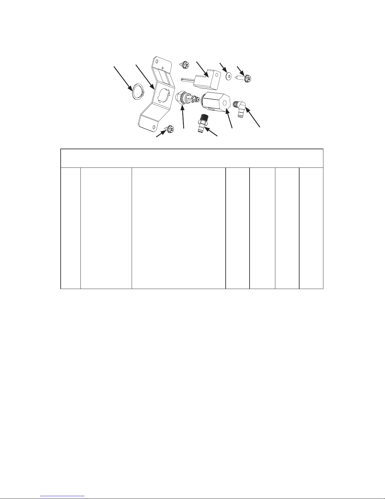
PARTS
NOZZLE ASSEMBLY
1
2
3
4 5
6
7
8
9
10
KEY QTY QTY QTY QTY
NO. PART NO. DESCRIPTION 110 160 175 220
1 160086-01 Stainless Steel Retaining Ring 1
2 160042-01 Nozzle Adapter Bracket 1 1 1
2 160042-02 Nozzle Adapter Bracket 1
3 160102-01 Screw, 10-16 x .38 2 2 2 2
4 160002-01 Ignitor 1 1 1 1
5 160093-01 Belleville Washer 1 1 1 1
6 160092-01 Screw, 6-32 x .88 1 1 1 1
7 160040-32 Orice Assembly 1
7 160040-20 Orice Assembly 1
7 160040-39 Orice Assembly 1
7 160040-41 Orice Assembly 1
8 160077-01 Brass Barb Fitting 1
9 160028-01 Nozzle Adapter 1 1 1
9 160028-02 Nozzle Adapter 1
10 160077-02 Barb Fitting, 90° 1
Note: Use only original replacement parts.
This will protect your warranty coverage for
parts replaced under warranty.
PARTS UNDER WARRANTY
Contact authorized dealers of this product. If
they can’t supply original replacement part(s),
call ProCom Heating, Inc. at 1-877-886-5989.
When calling ProCom Heating, Inc., have
ready:
• your name
• your address
• model and serial numbers of your heater
• how heater was malfunctioning
• purchase date
• place of purchase
Usually, we will ask you to return the part to
the factory. You may be asked to supply proof
of purchase.
PARTS NOT UNDER
WARRANTY
Contact authorized dealers of this product. If
they can’t supply original replacement part(s),
contact ProCom Heating, Inc. at 1-877-886-
5989.
When calling ProCom Heating, Inc., have
ready:
• model and serial number(s) of your
heater(s)
• the replacement part number
REPLACEMENT PARTS

PROCOM HEATING, INC. LIMITED WARRANTIES
New Products – Outdoor Heating
Standard Warranty: ProCom Heating, Inc. warrants this new product and any parts thereof to be free from
defects in material and workmanship for a period of one (1) year from the date of rst purchase from an
authorized dealer provided the product has been installed, maintained and operated in accordance with
ProCom Heating, Inc.’s warnings and Instructions.
For products purchased for commercial, industrial or rental usage, this warranty is limited to 90 days from
the date of rst purchase.
Factory Reconditioned Products
Limited Warranty: ProCom Heating, Inc. warrants factory reconditioned products and any parts thereof
to be free from defects in material and workmanship for a period 30 days from the date of rst purchase
from an authorized dealer provided the product has been installed, maintained and operated in accordance
with ProCom Heating, Inc.’s warnings and Instructions. No return will be authorized. Parts will be provided
to repair the product.
Terms Common to All Warranties
The following terms apply to all of the above warranties:
Always specify model number and serial number when contacting the manufacturer. To make a claim under
this warranty, the bill of sale or other proof of purchase must be presented.
This warranty is extended only to the original retail purchaser when purchased from an authorized dealer,
and only when installed by a qualied installer in accordance with all local codes and instructions furnished
with this product.
This warranty covers the cost of part(s) required to restore this product to proper operating condition and
an allowance for labor when provided by a ProCom Heating, Inc. Authorized Service Center or a provider
approved by ProCom Heating, Inc. Warranty parts must be obtained through authorized dealers of this
product and/or ProCom Heating, Inc. who will provide original factory replacement parts. Failure to use
original factory replacement parts will void this warranty.
Traveling, handling, transportation, diagnostic, material, labor and incidental costs associated with warranty
repairs, unless expressly covered by this warranty, are not reimbursable under this warranty and are the
responsibility of the owner.
Excluded from this warranty are products or parts that fail or become damaged due to misuse, accidents,
improper installation, lack of proper maintenance, tampering or alteration(s).
This is ProCom Heating, Inc.’s exclusive warranty, and to the full extent allowed by law; this express warranty
excludes any and all other warranties, express or implied, written or verbal and limits the duration of any
and all implied warranties, including warranties of merchantability and tness for a particular purpose to one
(1) year on new products and 30 days on factory reconditioned products from the date of rst purchase.
ProCom Heating, Inc. makes no other warranties regarding this product.
ProCom Heating, Inc.’s liability is limited to the purchase price of the product and ProCom Heating, Inc.
shall not be liable for any other damages whatsoever under any circumstances including direct, indirect,
incidental, or consequential damages.
Some States do not allow limitations on how long an implied warranty lasts or the exclusion or limitation of
incidental or consequential damages, so the above limitation or exclusion may not apply to you.
This warranty gives you specic legal rights, and you may also have other rights which vary from state to state.
160108-01
Rev A
08/12
WARRANTY
KEEP THIS WARRANTY
Model (
located on product or identication tag
) _____________________________
Serial No. (
located on product or identication tag
) __________________________
Date Purchased __________________________
Keep receipt for warranty verication.
ProCom Heating, Inc.
2800 Grifn Drive
Bowling Green, KY 42101
 Loading...