

Page 1
PROPANE CONSTRUCTION FORCED AIR HEATER
OWNER’S MANUAL
PCFA125V - 125,000 BTU/HR HEATER
PCFA175V - 175,000 BTU/HR HEATER
IMPORTANT: Read and understand this manual before
assembling, starting or servicing heater. Improper use
of heater can cause serious injury. Keep this manual for
future reference.
GENERAL HAZARD WARNING:
Failure to comply with the precautions and instructions
provided with this heater, can result in death, serious
bodily injury and property loss or damage from hazards
of re, explosion, burn, asphyxiation, carbon monoxide
poisoning and/or electrical shock.
Only persons who can understand and follow the in-
structions should use or service this heater.
If you need assistance or heater information such as an
instructions manual, labels, etc. contact the manufacturer.
Questions, problems, missing parts? Before returning to your retailer, call
our customer service department at 1-866-573-0674, 7:30 am - 4:15 pm CST,
Monday through Friday or email customerservice@usaprocom.com
Page 2
www.usaprocom.com
160495-01A2
TABLE OF CONTENTS
Specications ............................................ 2
Safety ........................................................ 3
Product Identication ................................. 4
Unpacking.................................................. 5
Assembly ................................................... 5
Theory of Operation................................... 5
Propane Supply ......................................... 6
Ventilation .................................................. 6
Installation ................................................. 6
Operation ................................................... 7
Storage ...................................................... 8
Maintenance .............................................. 8
Service Procedures ................................... 8
Troubleshooting ....................................... 12
Wiring Diagram ........................................ 13
Replacement Parts .................................. 13
Accessories ............................................. 13
Technical Services ................................... 13
Parts ........................................................ 14
Warranty .................................................. 16
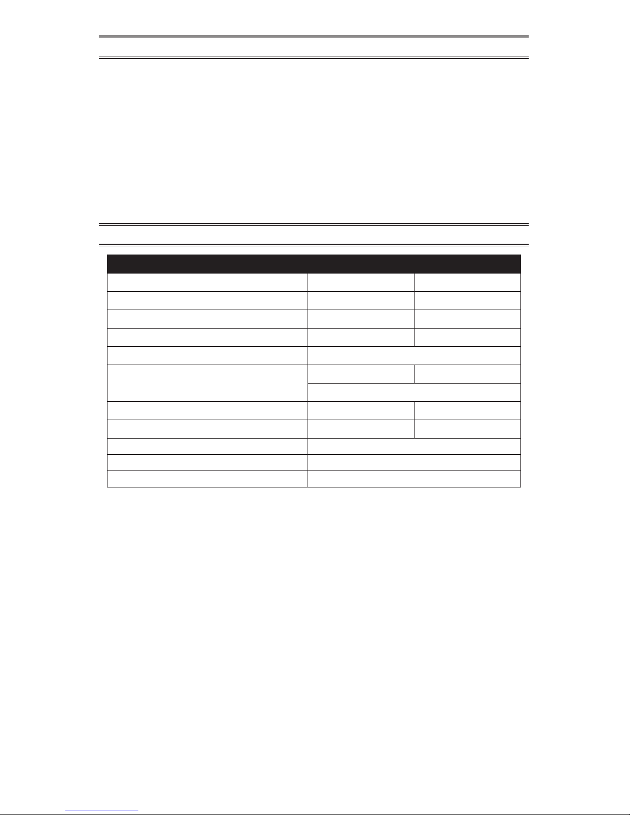
SPECIFICATIONS
Model PCFA125V PCFA175V
Output Rating 55-125,000 BTU/Hr 100-175,000 BTU/Hr
Fuel Consumption/Hour 5.8 lb (2.63 kg) 8.1 lb (3.7 kg)
Manifold Pressure 19.8 PSI 19.7 PSI
Ignition Electric Piezo Electric Spark
Fuel Propane Vapor
Supply Pressure To Regulator Minimum* 25 psi Minimum* 25 psi
Maximum Tank Pressure or 200 psi
Regulator Outlet Pressure 20 PSI 20 PSI
Motor 3000 RPM 3200 RPM
Electric Input 120 Volt/60 Hertz/1 Phase/3 Amp
Amperage 0.6
Temperature Range for Heater Operation 0° F to 85° F** (-17° C to 29.4° C**)
* For purposes of input adjustment
** When running heater in temperatures above 85° F (29.44° C), high internal temperatures may cause
thermal limit device to shut down heater.
Page 3
www.usaprocom.com
3160495-01A
SAFETY
Carbon Monoxide Poisoning: Some people
are more affected by carbon monoxide than
others. Early signs of carbon monoxide poisoning resemble the flu, with headaches, dizziness and/or nausea. If you have these signs,
the heater may not be working properly. Get
fresh air at once! Check for proper ventilation
and have heater serviced.
Propane Gas: Propane gas is odorless. An
odor-making agent is added to propane gas.
The odor helps you detect a propane gas
leak. However, the odor added to propane
gas can fade. Propane gas may be present
even though no odor exists.
Make certain you read and understand all
warnings. Keep this manual for reference. It
is your guide to safe and proper operation of
this heater.
1. Install and use heater with care. Follow
all local ordinances and codes. In the absence of local ordinances and codes, refer
to the Standard for Storage and Handling
of Liqueed Petroleum Gas, ANSI/NFPA
58 and the Natural and Propane Gas
Installation Code, CAN/CGA B149.1. This
instructs on the safe storage and handling
of propane gases.
2. Use only the electrical voltage and frequency specied on model plate. The
electrical connections and grounding of
the heater shall follow the National Electric
Code, ANSI/NFPA 70 or the Canadian
Electrical Code, Part 1.
3. Electrical grounding instructions - This
appliance is equipped with a three-prong
(grounding) plug for your protection against
shock hazard and should be plugged directly into a properly grounded three-prong
receptacle or extension cord.
4. This product has been approved for use
in the Commonwealth of Massachusetts.
5. Use only a three-prong, grounded extension cord.
6. Use only the hose and factory preset
regulator provided with the heater.
7. Use only propane gas set up for vapor
withdrawal.
8. Provide adequate ventilation. Before
using heater, provide at least a 1.5 ft2
(1400 cm2) opening of fresh, outside air.
9. When used indoors, adequate ventilation
must be provided.
WARNING: This product
contains and/or generates
chemicals known to the State
of California to cause cancer or
birth defects or other reproductive harm.
WARNING: Fire, burn, in-
halation and explosion hazard.
Keep solid combustibles, such
as building materials, paper or
cardboard, a safe distance away
from the heater as recommended
by the instructions. Never use
the heater in spaces which do or
may contain volatile or airborne
combustibles or products such
as gasoline, solvents, paint thinner, dust particles or unknown
chemicals.
WARNING: Not for home or
recreational vehicle use.
For use with Propane/LP gas only.
The heater is designed for use as a construction heater in accordance with ANSI
Z83.7•CGA2.14. Other standards govern
the use of fuel gases and heating products
for specic uses. Your local authority can
advise you about these. The primary purpose
of construction heaters is to provide temporary heating of buildings under construction,
alteration or repair. Properly used, the heater
provides safe economical heating. Products
of combustion are vented into the area being
heated.
We cannot foresee every use which may be
made of our heaters. Check with your local
re safety authority if you have questions
about heater use.
Other standards govern the use of fuel gases
and heat producing products for specific
uses. Your local authorities can advise you
about these.
DANGER: Carbon monoxide
poisoning may lead to death!
Page 4
www.usaprocom.com
160495-01A4
SAFETY
10. Do not use heater in occupied dwellings
or in living or sleeping quarters.
11. Do not use heater in basement or below
ground level. Propane gas is heavier than
air. If a leak occurs, propane gas will sink
to the lowest possible level.
12. Keep appliance area clear and free from
combustible materials, gasoline, paint
thinner and other flammable vapors and
liquids.
13. Do not use heater in areas with high dust
content. Dust is combustible.
14. Minimum heater clearances from combustibles:
Outlet: 8 Ft. (2.4 m)
Sides: 2 Ft. (0.61 m), Top: 6 Ft. (1.83 m)
Rear: 2 Ft. (0.61 m)
Locate 10 ft. (3 m) from canvas or plastic
tarpaulins or similar coverings and secure
them to prevent flapping or movement due
to wind action.
15. Keep heater at least 6 feet (1.83 m) from
propane tank(s) in USA or 10 feet (3 m)
from propane tank(s) in Canada. Do not
point heater at a propane/LP tank within
20 feet (6.1 m).
16. Keep propane tank(s) below 100° F
(37.8° C).
17. Check heater for damage before each
use. Do not use a damaged heater.
18. Check hose before each use of heater.
If highly worn or cut, replace with hose
specied by manufacturer before using
heater.
19. Locate heater on a stable and level surface.
Do not move while heater is hot or running.
Position heater properly before use.
20. Not intended for use on nished floors.
21. Never block air inlet (rear) or air outlet
(front) of heater.
22. Keep heater away from strong drafts,
water spray, rain or dripping water.
23. Do not leave heater unattended.
24. Keep children and animals away from
heater.
25. Never move, handle or service a hot, operating or plugged-in heater. Severe burns
may result. You must wait 15 minutes after
turning heater off.
26. To prevent injury, wear gloves when handling heater.
27. Never attach duct work to front or rear of
heater.
28. Do not alter heater. Keep heater in its
original state.
29. Do not use heater if altered.
30. Turn off propane supply and unplug heater
when not in use.
31. Use only original replacement parts. This
heater must use design-specic parts.
Do not substitute or use generic parts.
Improper replacement parts could cause
serious or fatal injuries.
32. Do not use this product without leg and
feet assembly.
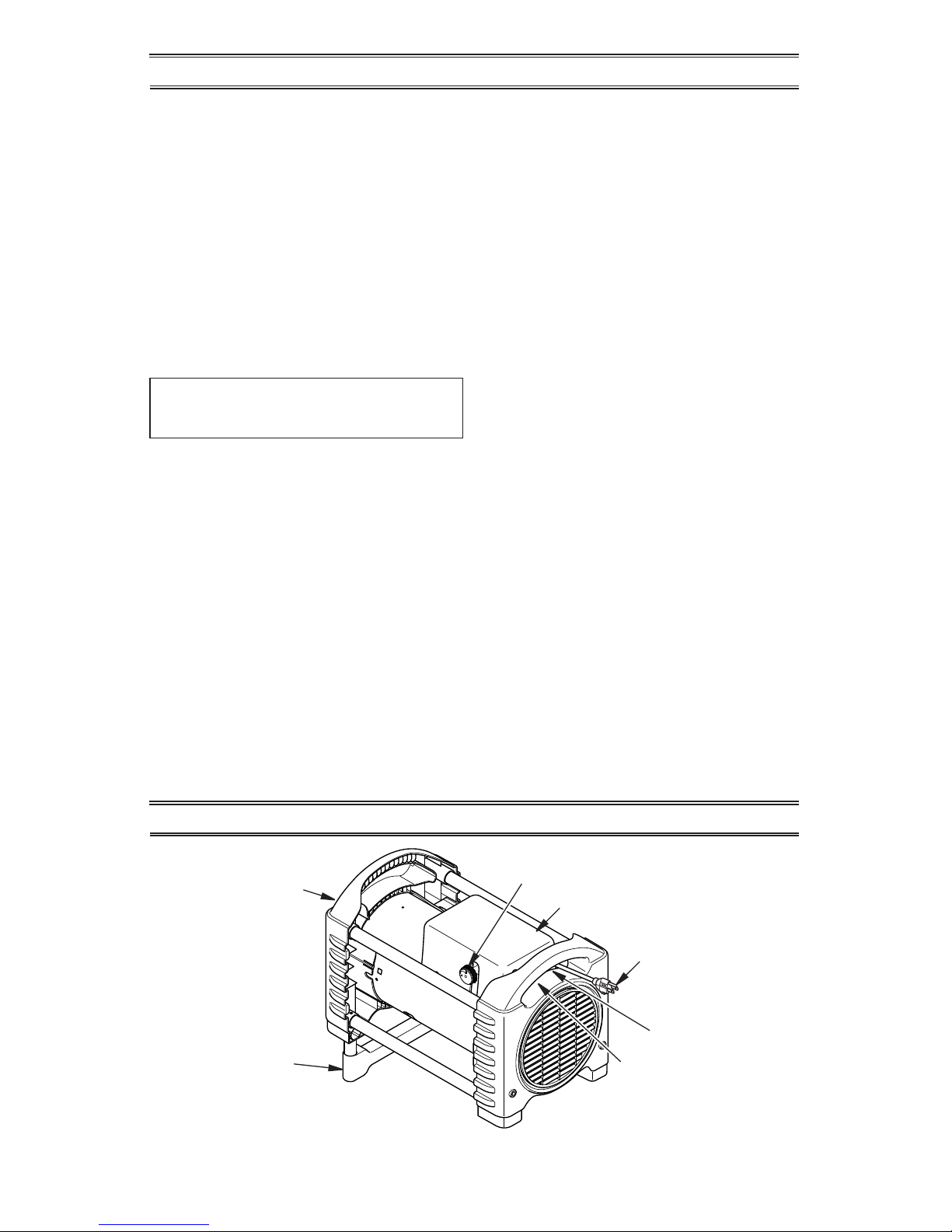
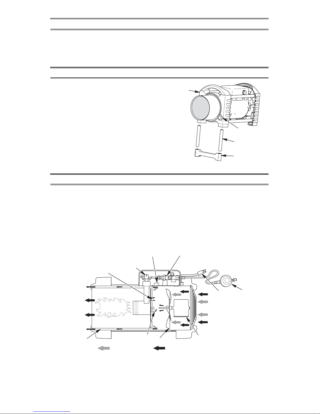
Hot Air Outlet
(Front)
Power Cord
Burn Rate
Adjustment Knob
Burner Assembly Cover
Control Valve Button
Valve Inlet
Adjustable
Foot
Figure 1 - 125,000 & 175,000 Btu/Hr Heater
PRODUCT IDENTIFICATION
Page 5
www.usaprocom.com
5160495-01A
UNPACKING
1. Remove all packing items applied to
heater for shipment. Keep plastic cover
caps (attached to inlet connector and
hose/regulator assembly) for storage.
2. Remove all items from carton.
3. Check all items for shipping damage. If
heater is damaged, call our customer
service department at 1-866-573-0674.
End Cap
Leg Extension
Base Foot
Fastener
Screw
Figure 2 - Foot Assembly
THEORY OF OPERATION
The Fuel System: The hose/regulator assembly attaches to the propane gas supply. The
propane gas moves through the automatic
control valve, burn rate adjustment valve and
out the injector.
The Air System: The motor turns the fan. The
fan pushes air into and around the combustion
chamber. This air is heated and provides a
stream of clean, hot air.
The Ignition System: The high voltage ignitor
sends voltage to the spark ignitor. The spark
ignitor ignites the fuel and air mixture.
The Safety Control System: This system
causes the heater to shut down if the flame
goes out. The motor will continue to run, but
no heat is produced.
Air For
Combustion
Air For
Heating
Cool
Air In
(Back)
Motor
Hose/
Regulator
Assembly
Spark Ignitor
Combustion
Chamber
Figure 3 - Cross Section Operational View
Fan
Clean
Heated
Air Out
(Front)
Power
Cord
Injector
Thermal
Limit Switch
High Voltage Ignitor
Automatic Control Valve
ASSEMBLY
IMPORTANT: Do not use this product without
leg and foot assembly.
Plastic Foot and Leg Extensions
1. Insert leg extensions into outlet end cap
until small hole lines up with larger hole,
visible from inside of outlet end cap (see
Figure 2). Fasten leg extensions with
provided Fastener screws.
2. Insert plastic base foot into each leg extension and set heater to desired angle.
Small post screws on plastic foot will snap
into holes in leg extensions.
Page 6
www.usaprocom.com
160495-01A6
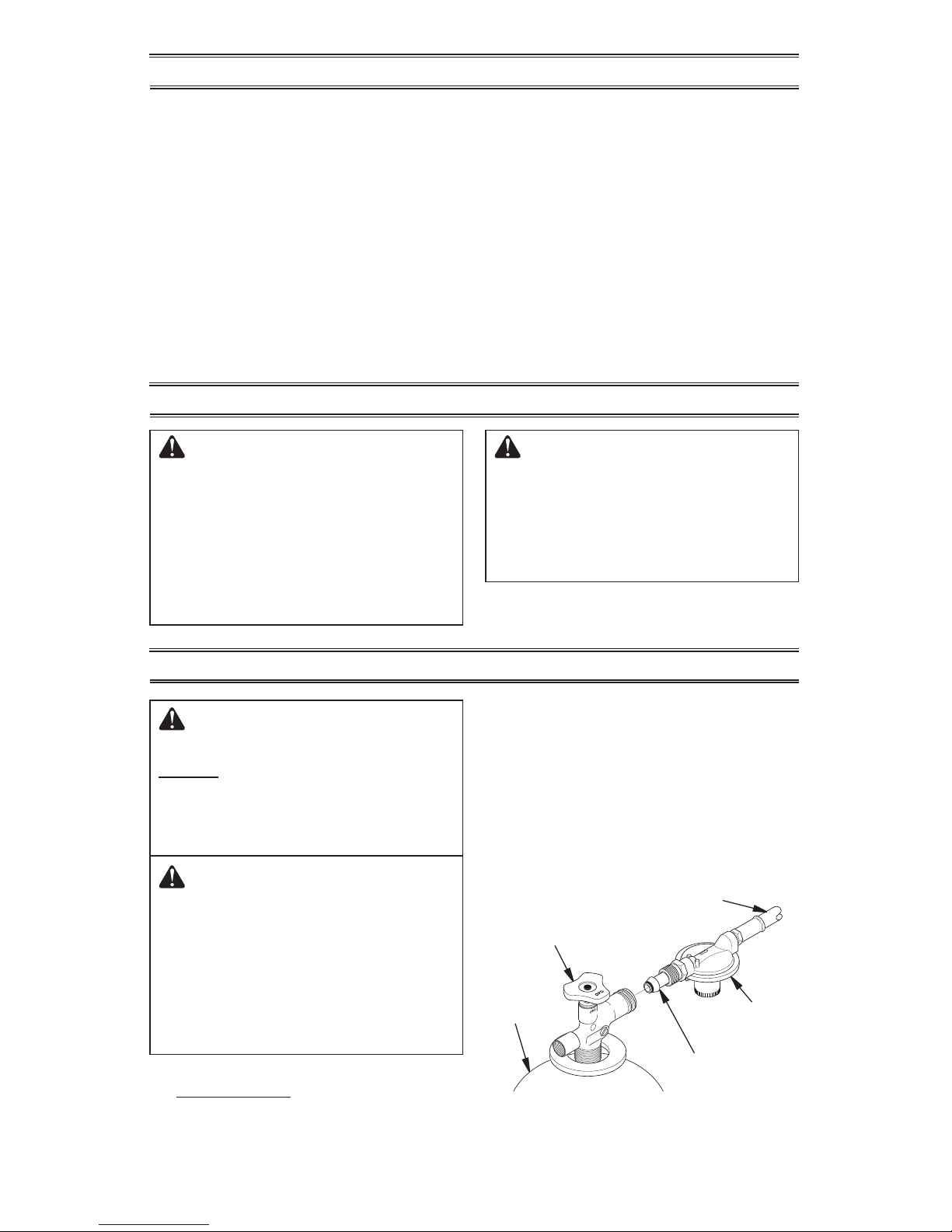
Figure 4 - Regulator Position
Propane
Tank
Propane Supply
Valve
Regulator
Hose
POL
Fitting
VENTILATION
WARNING: Review and understand the warnings in the
Safety, page 3. They are needed
to safely operate this heater. Follow all local codes when using
this heater.
WARNING: Test all gas piping
and connections for leaks after
installation or servicing. Never
use an open ame to check for
a leak. Apply a noncorrosive
leak detection uid to all joints.
Bubbles forming show a leak.
Correct all leaks at once.
1. Provide propane supply system (see
Propane Supply).
2. Connect POL tting on hose/regulator
assembly to propane tank(s). Turn POL
tting counterclockwise into threads on
tank. Tighten rmly using wrench.
IMPORTANT: Position regulator so that
hose leaving the regulator is in a horizontal position (see Figure 4). This places
the regulator vent in the proper position to
protect it from the weather.
WARNING: Follow the mini-
mum fresh, outside air ventila-
tion requirements. If proper
fresh, outside air ventilation is
not provided, carbon monoxide
poisoning can occur. Provide
proper fresh, outside air ventilation before running heater.
WARNING: Provide a fresh
air opening of at least a 3 ft2
(0.91 m2) for each 100,000 Btu/
Hr (105,500 k/j) rating. Provide
extra fresh air if more heaters
are being used.
INSTALLATION
PROPANE SUPPLY
Propane gas and propane tank(s) are to be
furnished by the user.
Use this heater only with a propane vapor
withdrawal supply system. See Chapter 5
of the Standard for Storage and Handling of
Liqueed Petroleum Gas, ANSI/NFPA 58 and/
or CAN/CGA B149.2. Your local library or re
department will have this booklet.
The amount of propane gas ready for use
from propane tanks varies. Two factors decide
this amount:
1. The amount of propane gas in tank(s)
2. The temperature of tank(s)
The chart below shows the number of 100 lb
(45 kg) tanks needed to run this heater.
Average Temp No. Of Tanks
At Tank Location 100 lb (45 kg)
Above 20° F (-7° C) 2
20° F (-7° C) to -0° F (-18° C) 3
Less gas is vaporized at lower temperatures.
You may need a larger tank in colder weather.
Your local propane gas dealer will help you
select the proper supply system.
Page 7
www.usaprocom.com
7160495-01A
OPERATION
Figure 5 - Hose and Inlet Connector
Hose
Inlet Connector
Gas Valve Button
WARNING: Review and understand the warnings in the
Safety, page 3. They are needed
to safely operate this heater. Follow all local codes when using
this heater.
TO START HEATER
1. Follow all installation, ventilation and
safety information.
2. Locate heater on stable and level surface.
Make sure strong drafts do not blow into
front or rear of heater.
3. Plug power cord of heater into a threeprong, grounded extension cord. Extension cord must be at least 6 feet long.
Extension cord must be UL listed.
Extension Cord Wire Size Requirements
Up to 50 ft (15.24 m) long, use 18 AWG
rated cord.
51 to 100 ft (15.54 to 30.48 m) long, use
16 AWG rated cord.
101 to 200 ft (30.78 to 60.96 m) long, use
14 AWG rated cord.
4. Plug extension cord into a 120 volt/60
hertz, 3-hole, grounded outlet.
5. Open propane supply valve on propane
tank(s) slowly. Note: If not opened slowly,
excess-flow check valve on propane
tank will signicantly reduce gas ow. If
this happens, you may hear a click inside
the regulator assembly and/or notice the
heater burning at a very low heat output.
You will not be able to increase heat output
when you adjust heat setting knob. Do not
run heater in this condition. To reset the
excess ow check valve, close propane/LP
supply valve and open again slowly.
6. Press and hold in gas valve button. Heater
should ignite within a few seconds. Note:
If heater fails to ignite, hose may have air
in it. If so, keep gas valve button pressed
and wait 20 seconds. Release gas valve
button and wait 20 seconds for unburned
fuel to exit heater. Repeat step 6.
7. After heater ignites, wait 30 seconds. This
activates the automatic control system.
Release the gas control valve button.
8. Adjust burn rate with knob.
TO STOP HEATER
1. Tightly close propane supply valve on
propane tank(s).
2. Wait a few seconds. Heater will burn gas
left in supply hose.
3. Unplug heater.
TO RESTART HEATER
1. Wait ve minutes after stopping heater.
2. Repeat steps under To Start Heater.
INSTALLATION
3. Connect hose to valve inlet (see Figure 4,
page 6). Tighten rmly using a wrench.
IMPORTANT: Use extra hose or piping
if needed. Install extra hose or piping
between hose/regulator assembly and
propane tank. You must use the regulator
supplied with heater.
4. Open propane supply valve on propane
tank(s) slowly. Note: If not opened slowly,
excess-ow check valve on propane tank
will signicantly reduce gas ow. If this
happens, you may hear a click inside
the regulator assembly and/or notice the
heater burning at a very low heat output.
You will not be able to increase heat output
when you adjust heat setting knob. Do not
run heater in this condition. To reset the
excess ow check valve, close propane/LP
supply valve and open again slowly.
5. Check all connections for leaks. Apply a
noncorrosive leak detection fluid to gas
joints. Bubbles forming show a leak that
must be corrected.
6. Close propane supply valve.
Page 8
www.usaprocom.com
160495-01A8
MAINTENANCE
WARNINGS
• Never service heater while it
is plugged in, connected to
propane supply, operating or
hot. Severe burns and electrical shock can occur.
• Keep heater clear and free
from combustible materials,
gasoline and other ammable
vapors and liquids.
• Do not block the ow of com-
bustion or ventilation air.
1. Keep heater clean. Clean heater annually
or as needed to remove dust and debris. If
heater is dirty or dusty, clean heater with
a damp cloth. Use household cleaners on
difcult spots.
2. Inspect heater before each use. Check
connections for leaks. Apply noncorrosive leak detection fluid to connections.
Bubbles forming show a leak. Correct all
leaks at once.
3.
Inspect hose/regulator assembly before
each use. If hose is highly worn or cut, replace with hose specied by manufacturer.
4. Have heater inspected yearly by a qualied service agency.
5. Keep inside of heater free from combustible
and foreign objects.
6. Clean fan blades each season or as
needed.
SERVICE PROCEDURES
WARNING: Never service
heater while it is plugged in,
connected to propane supply,
operating or hot. Severe burns
and electrical shock can occur.
ELECTRICAL SYSTEM
The entire electrical system for this heater is
contained within the top cover. If any part of
the electrical system is damaged, you must
replace with OEM parts (see page 13).
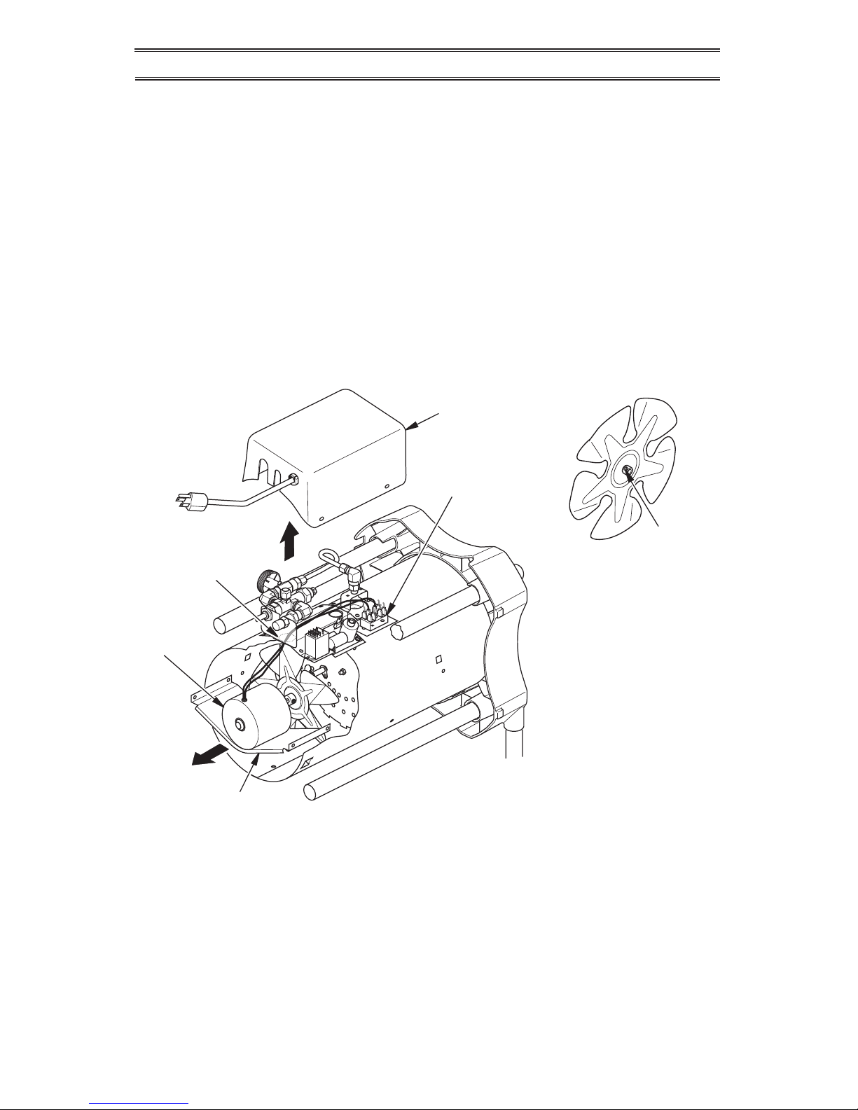
MOTOR
1. Remove screws on top cover using a
Phillips head screw driver.
2. Remove top cover.
3. Detach the motor and fan wires from terminal block under top cover (see Figure
6, page 9).
4. Remove fan guard from rear of heater.
Fan guard will snap out of shell.
5. Reach into rear of heater shell. Carefully
pull wires through hole in the bracket.
Note: Pull wires through hole one at a time.
6. Remove screws holding motor mount to
shell. Use 5/16" nut driver or Phillips head
screw driver.
7. Carefully pull motor and fan out of shell.
IMPORTANT: Be careful not to damage
fan. Do not set motor and fan down with
the weight resting on fan. This could damage fan pitch.
STORAGE
CAUTION: Disconnect heater
from propane supply tank(s).
1. Store propane tank(s) in safe manner. See
Chapter 5 of Standard for Storage and
Handling of Liqueed Petroleum Gases,
ANSI/NFPA 58. Follow all local codes.
Always store propane tanks outdoors.
2. Place plastic cover caps over brass ttings
on inlet connector and hose/regulator assembly.
3. Store in dry, clean and safe place. Do
not store hose/regulator assembly inside
heater combustion chamber.
4. When taking heater out of storage, always
check inside of heater. Insects and small
animals may place foreign objects in
heater. Keep inside of heater free from
combustible and foreign objects.
Page 9
www.usaprocom.com
9160495-01A
8. Use hex wrench to loosen set screw which
holds fan to motor shaft (see Figure 7).
Remove fan. Be careful not to damage
the fan blade pitch.
9. Use a nut driver to remove two nuts that
attach motor to motor mounting bracket.
10. Disconnect the green power cord wire
from motor and remove black and white
wire terminals.
11. Discard old motor.
12. Attach green power cord wire to new motor.
13. Replace black and white terminals.
14. Attach new motor to motor mounting
bracket with 2 nuts. Tighten nuts rmly.
15. Place fan onto motor shaft of new motor. Make sure set screw contacts flat
Terminal
Block
Figure 6 - Removing Fan and Motor
Top
Cover
Motor
Motor Mounting Bracket
Hole in Bracket
SERVICE PROCEDURES
surface on motor shaft. Tighten set screw
rmly (40-50 inch-pounds [46.08-57.60
kilogram-centimeters]).
16. Place motor and fan guard into rear of
heater shell. Make sure power cord is
properly located.
17. Line up mounting holes in shell with
holes on motor mount. Replace 4 screws
through shell and motor mount.
18. Route motor wires through hole in top of
shell (see Figure 6).
19. Reconnect motor and fan wires to the
same posts on terminal block as removed
in step 3, page 8 (see Figure 6).
20. Replace top cover.
21. Replace fan guard.
Figure 7 - Setscrew
Location
Setscrew
FAN
Clean fan every 500 hours of operation or
as needed.
1. Remove screws on top cover using a
Phillips head screw driver.
2. Remove top cover.
3. Detach the 2 black motor wires from terminal block under top cover. Be sure to
detach only wires coming from motor.
4. Remove fan guard from rear of heater.
Fan guard will snap out of shell.
5. Reach into rear of heater shell. Carefully
pull motor wires through hole in bracket.
Note: Pull wires through hole one at a time.
6. Remove screws holding motor mount to
shell. Use 5/16" nut driver or Phillips head
screw driver.
Page 10
www.usaprocom.com
160495-01A10
SERVICE PROCEDURES
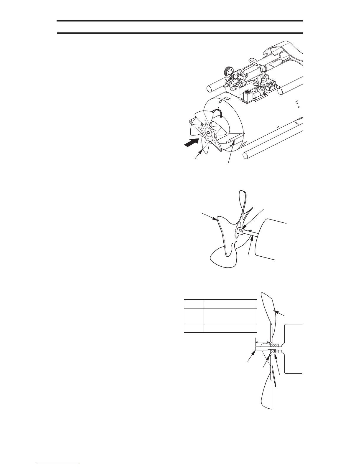
A
Fan
Hub
Setscrew
Motor
Figure 10 - Fan Cross Section
Model Distance A
125 0.5" (12.7 mm)* or
0.9" (22.9 mm)*
175 0.25" (6.4 mm)
Motor
Shaft
* Depending
on Motor Shaft
Figure 9 - Fan, Motor Shaft and Setscrew
Identication
Motor
Shaft
Fan
Setscrew
7. Carefully pull motor and fan out of shell.
IMPORTANT: Be careful not to damage
fan. Do not set motor and fan down with
the weight resting on fan. This could damage fan pitch.
8. Turn motor and fan around. Place motor
and fan into shell backwards. Note: Motor
will go into shell rst (see Figure 8).
9. Line up rear mounting holes in shell with
rst hole on each side of motor mount (see
Figure 8). Note: When holes are lined up,
fan should be outside of shell.
10. Holding mounting screws, carefully reach
through fan blades into rear of heater. Be
careful not to damage fan pitch. Insert
screw through motor mount and shell.
With free hand, attach screw nger tight.
Repeat process for other mounting hole.
11. Use 1/8" hex wrench to loosen setscrew
which holds fan to motor shaft (see Figure 9).
12. Slip fan off motor shaft.
13. Clean fan using soft cloth moistened with
a cleaning solvent.
14. Dry fan thoroughly.
15. Replace fan on motor shaft. Place setscrew on flat of shaft. See chart in Figure
10 for distance of fan hub from end of
motor shaft. Tighten setscrew rmly (4050 inch-pounds).
16. Remove screws securing motor mount to
shell.
17. Pull motor and fan from shell. Turn motor
and fan around. Carefully place back in
shell. Note: Fan will go into shell rst.
18. Line up mounting holes in shell with
holes on motor mount. Replace 4 screws
through shell and motor mount.
19. Route motor wires through hole in top of
shell (see Figure 6, page 9).
20. Reconnect motor wires to the same posts
on terminal block as removed in step 3,
page 8 (see Figure 6, page 9).
21. Replace top cover.
22. Replace fan guard.
Figure 8 - Fan and Motor Reversed for
Cleaning
Fan
Motor Mounting Bracket
Page 11
www.usaprocom.com
11160495-01A
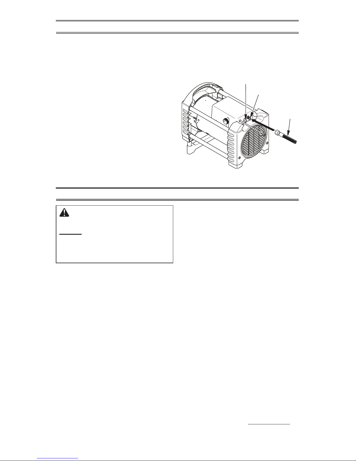
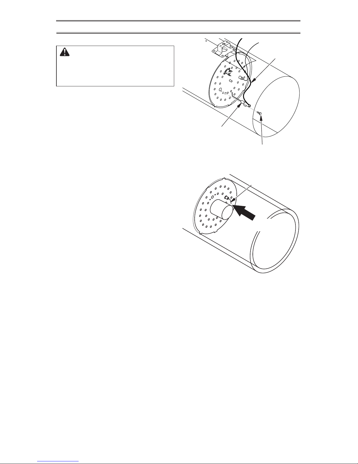
Figure 11 - Removing Ignitor Mounting
Screw and Ignitor
Ignitor
Ignitor
Wire
Mounting Screw
Figure 12 - Clearance Between Ignitor
Electrode and Burner
Ignitor Electrode
Gap
Area
SERVICE PROCEDURES
IGNITOR
WARNING: Make sure heater
is disconnected from propane
supply. Heater could ignite causing severe burns.
1. Remove motor and fan guard from heater
(see page 8, steps 1 through 7).
2. Remove orange ignitor wire from ignitor
electrode.
3. Remove ignitor mounting screw from
rear head using nut-driver or standard
screwdriver (see Figure 11).
4. Remove ignitor from rear head.
5. Install new ignitor. Attach ignitor to rear
head with ignitor mounting screw.
6. Install orange ignitor wire onto quick connect terminal on ignitor electrode.
7. Set gap between ignitor electrode and
burner to 0.17" (43.18 cm) (see Figure 12).
8. Place motor and fan guard into rear
of heater shell (see page 9, steps 16
through 21).
Page 12
www.usaprocom.com
160495-01A12
TROUBLESHOOTING
WARNING: Never service heater while it is plugged in, connected
to propane supply, operating or hot. Severe burns and electrical
shock can occur.
WARNING: Use only in areas free of high dust content.
Problem Possible Cause Corrective Action
Fan does not turn when
heater is plugged in.
1. No electrical power to heater.
2. Fan hitting inside of heater
shell.
3. Fan blades bent.
4. Defective motor.
1. Check voltage to electrical
outlet. If voltage is good,
check heater power cord for
breaks.
2. Adjust motor/fan guard to
keep fan from hitting inside
of heater shell. Bend fan
guard if necessary.
3.
Replace fan. See Fan, page 8.
4. Replace motor. See Service
Procedures, page 8.
Heater will not ignite. 1. User did not follow installa-
tion or operation instructions
properly.
2. No spark at ignitor. To test
for spark, follow step 8 under
Ignitor, page 11. If you see
spark at ignitor, have heater
serviced by qualied service
person. If no spark seen:
A) Loose or disconnected
ignitor wire
B) Wrong spark gap
C) Piezo ignitor loose
D) Bad ignitor electrode
1. Repeat installation and operation instructions. See
Installation, page 6 and
Operation, page 7.
2. A) Check ignitor wire. Tighten or reattach loose ignitor
wire. See Figure 10, page
11 for ignitor wire location
B) Set gap between ignitor
electrode and target plate to
0.17" (0.43 cm)
C) Replace ignitor electrode.
See Ignitor, page 11.
Heater shuts down while
running.
1. High surrounding air temperature causing thermal
limit device to shut down
heater.
2. Restricted air flow.
3. Damaged fan.
4. Excessive dust or debris in
surrounding area.
1. This can happen when running heater in temperatures
above 85° F (29.44° C). Run
heater in cooler temperatures.
2 Check heater inlet and out-
let. Remove any obstructions.
3. Replace fan. See Fan, page 8.
4. Clean heater. See Mainte-
nance, page 8.
Page 13
www.usaprocom.com
13160495-01A
ACCESSORIES
Purchase these accessories from your local dealer. If they can not supply these accessories,
call ProCom Heating, Inc. at 1-866-573-0674 for information.
TECHNICAL SERVICES
You may have further questions about installation, operation, or troubleshooting. If so, contact
ProCom Heating, Inc. at 1-866-573-0674. When calling please have your model and serial
numbers of your heater ready.
You can also visit ProCom Heating, Inc.’s web site at www.usaprocom.com.
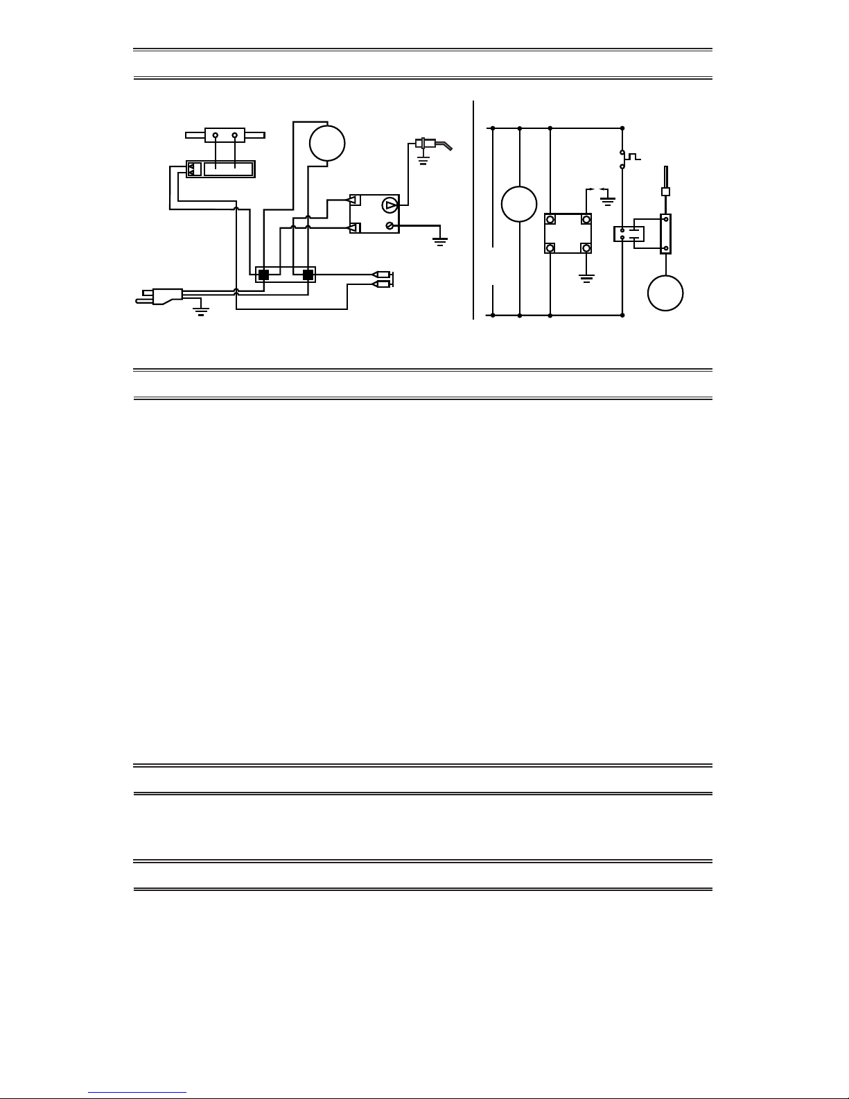
WIRING DIAGRAM
Black** or Orange**/
Negro** o Naranja**/
Noir** ou orange**
L1
L2
White/Blanco/
Blanc
Blue*/Azul*/Bleu*
Blue*/Azul*/Bleu*
Blue/Azul/Bleu
White/Blanco/
Blanc
White/Blanco/Blanc
Black/
Negro/Noir
Black/Negro/Noir
Black/Negro/Noir
Black/Negro/Noir
Green/
Verde/
Vert
Orange/
Naranja
Orange/
Naranja
Orange/
Naranja
Orange/
Naranja
Thermocouple/Termopar
CONNECTION DIAGRAM/DIAGRAMA DE CONEXIONES/
DIAGRAMME DE CONNEXION
SCHEMATIC DIAGRAM/DIAGRAMA ESQUEMÁTICO/
DIAGRAMME DE CIRCUIT
60,000/125,000/175,000 Models/Modelos
Relay/Relé/Relais
Motor/
Moteur
Ignitor/
Encendedor/
Allumeur
High-Limit Switch/
Interruptor de
límite alto/
Commutateur de
limite supérieure
• If any original wiring as supplied with the heater must be replaced, it must be replaced with type AWG 105° C
wire or its equivalent except as indicated (*Type SF2-200. **UL Style 3257 250° C)
Line Cord/
Cable de línea/
Cordon électrique
Motor/
Moteur
High Limit Switch/
Interruptor de límite alto/
Interrupteur de
limite supérieure
White/Blanco/Blanc
Black/Negro/Noir
115V
60HZ
Gas
Valve
Relay/
Relé/
Relais
Thermocouple/
Termopar
Green/Verde/Vert
L1
L2
Ignitor/
Encendedor/
Allumeur
Válvula de gas/
Robinet de gaz
Electrode/Electrodo/
Électrode
Electrode/Electrodo/
Électrode
• Label all wires prior to disconnecting.
REPLACEMENT PARTS
Note: Use only original replacement parts. This will protect your warranty coverage for parts
replaced under warranty.
PARTS NOT UNDER WARRANTY
Contact authorized dealers of this product.
If they can’t supply original replacement
part(s) call Customer Service toll free at
1-866-573-0674 for referral information.
When calling Customer Service have ready:
• Model number of your heater
• The replacement part number
PARTS UNDER WARRANTY
Contact authorized dealers of this product.
If they can’t supply original replacement
parts, call Customer Service toll free at
1-866-573-0674 for referral information.
When calling Customer Service or your
dealer, have ready:
• Your name
• Your address
• Model and serial number of your heater
• How heater was malfunctioning
• Type of gas supply and Propane/LP tank
size
• Purchase date
Usually, we will ask you to return the defective
part to the factory
Page 14

www.usaprocom.com
160495-01A14
PARTS
MODELS PCFA125V AND PCFA175V
8
18
17
16
10
9
15
12
11
14
13
7
5
4
4
2
27
26
1
6
3
9
20
19
21
23
22
24
25
29
30
31
32
28
Page 15
www.usaprocom.com
15160495-01A
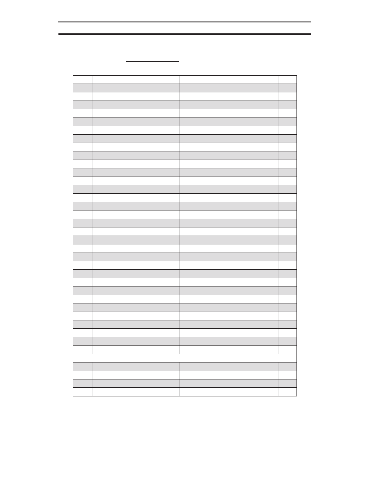
PARTS
MODELS PCFA125V AND PCFA175V
This list contains replaceable parts used in your heater. When ordering parts, follow the
instructions listed under Replacement Parts on page 13 of this manual.
Item PCFA125V PCFA175V Description Qty
1 ** ** Shell 1
2 ** ** Combustion Chamber 1
3 160504-01 160504-01 Cage Tube 4
4 ** ** End Cap 2
5 160238-01 160238-01 Fastener Screw 2
6 160497-01 160497-01 Fan Guard 1
7 160503-01 160503-01 Foot Tube 2
8 160502-01 160502-01 Base Foot 1
9 160482-02 160482-02 Burner Assembly 1
10 160510-01 160523-01 Rear Plate 1
11 160481-02 160481-02 Ignitor Electrode 1
12 160102-03 160102-03 Screw, HWH AB 8-32 x 0.38 1
13 160440-03 160440-04 Thermostat Switch 1
14 160441-02 160441-02 Screw, Thermal Hex 4-40 x 1/4 1
15 160449-02 160449-02 Thermocouple 1
16 160505-01 160524-01 Fan 1
17 160499-01 160525-01 Motor 1
18 160500-01 160500-01 Motor Bracket 1
19 160318-01 160318-01 Power Cord 1
20 PF06-1201-D PF06-1201-D Strain Relief Bushing 1
21 160477-01 160477-01 Brass Adaptor 1
22 160476-01 160476-01 Control Valve 1
23 160509-01 160509-01 Brass Elbow 1/4 NPT Female/Male 2
24 160294-03 160294-04 Ball Valve Assembly 1
25 160478-01 160478-01 Brass Fitting, 1/4 NPT 1
26 160304-01 160304-01 Control Knob 1
27 160480-05 160480-05 Tube 1
28 160474-02 160474-03 Injector 1
29 160508-01 160508-01 Female Elbow 1
30 160483-01 160483-01 Terminal Block 1
31 160485-01 160485-01 Ignitor Assembly 1
32 160479-01 160479-01 Relay Assembly 1
PARTS AVAILABLE - NOT SHOWN
160519-01 160519-01 Operation Decal 1
160493-01 160493-02 Model Data Decal 1
160518-01 160518-01 Wiring Diagram Decal 1
160468-01 160468-01 Hose/Regulator Assembly 1
** Not a eld replaceable part.
Page 16

160495-01
Rev. A
07/13
REGISTER YOUR PRODUCT AT WWW.USAPROCOM.COM
IMPORTANT: We urge you to register your product within 10 days of date of installation, complete
with entire serial number which can be found on the rating plate. Please ll out the warranty information above for your personal records. Retain this manual for future reference.
Always specify model and serial numbers when communicating with customer service.
We reserve the right to amend these specications at any time without notice. The only warranty applicable
is our standard written warranty. We make no other warranty, expressed or implied.
LIMITED WARRANTY
ProCom Heating, Inc. warrants this product to be free from defects in materials and components for ONE
(1) year from the date of rst purchase, provided that the product has been properly installed by a qualied
installer in accordance with all local codes and instructions furnished with the unit, operated and maintained in accordance with all applicable instructions. To make a claim under this warranty, the Bill of Sale
or cancelled check must be presented.
RESPONSIBILITY OF OWNER
This warranty is extended only to the original retail purchaser. This warranty covers the cost of part(s)
required to restore this heater to proper operating condition. Warranty part(s) MUST be obtained through
ProCom Heating, Inc. who will provide original factory replacement parts. Failure to use original factory
replacement parts voids this warranty. The heater MUST be installed by a qualied installer in accordance
with all local codes and instructions furnished with the unit.
WHAT IS NOT COVERED
This warranty does not apply to parts that are not in original condition because of normal wear and tear or
parts that fail or become damaged as a result of misuse, accidents, lack of proper maintenance or defects
caused by improper installation. Travel, diagnostic cost, labor, transportation and any and all such other
costs related to repairing a defective heater will be the responsibility of the owner.
TO THE FULL EXTENT ALLOWED BY THE LAW OF THE JURISDICTION THAT GOVERNS THE SALE
OF THE PRODUCT, THIS EXPRESS WARRANTY EXCLUDES ANY AND ALL OTHER EXPRESSED
WARRANTIES AND LIMITS THE DURATION OF ANY AND ALL IMPLIED WARRANTIES. INCLUDING
WARRANTIES OF MERCHANTABILITY AND FITNESS FOR A PARTICULAR PURPOSE TO TWO (2)
YEARS ON ALL COMPONENTS FROM THE DATE OF FIRST PURCHASE. PROCOM HEATING, INC.'S
LIABILITY IS HEREBY LIMITED TO THE PURCHASE PRICE OF THE PRODUCT AND PROCOM HEATING, INC. SHALL NOT BE LIABLE FOR ANY OTHER DAMAGES WHATSOEVER INCLUDING INDIRECT.
INCIDENTAL OR CONSEQUENTIAL DAMAGES.
Some states do not allow a limitation on how long an implied warranty lasts or an exclusion or limitation of
accidental or consequential damages, the above limitation on implied warranties, or exclusion or limitation
on damages may not apply to you.
This warranty gives you specic legal right, and you may also have other rights that vary from state to state.
WARRANTY
KEEP THIS WARRANTY
Model _______________________________
Serial No. ____________________________
Date Purchased _______________________
Keep receipt for warranty verication.
ProCom Heating, Inc.
Bowling Green, KY 42101
www.usaprocom.com
1-866-573-0674
Page 17

¿Preguntas, problemas, piezas faltantes? Antes de volver a la tienda, llame a
nuestro Departamento de Servicio al Cliente al 1-866-573-0674, de lunes a viernes de
7:30 a.m. a 4:15 p.m., Hora del Centro, o envíe un correo electrónico a
customerservice@usaprocom.com.
CALENTADOR DE AIRE FORZADO DE PROPANO
PARA CONSTRUCCIÓN
MANUAL DEL PROPIETARIO
IMPORTANTE: Lea y comprenda este manual antes de
ensamblar, encender o dar servicio al calentador. El
uso inadecuado del calentador puede causar lesiones
graves. Conserve este manual para referencias futuras.
ADVERTENCIA GENERAL DE PELIGRO:
No cumplir con las precauciones e instrucciones proporcionadas con este calentador puede causar la muerte,
lesiones físicas graves y pérdidas o daños a la propiedad
debido al peligro de incendio, explosión, quemaduras,
asxia, intoxicación con monóxido de carbono y/o choques eléctricos.
Únicamente las personas que puedan entender y seguir las
instrucciones deberán usar o dar servicio a este calentador.
Si necesita ayuda o información sobre el calentador,
como manuales de instrucciones, etiquetas, etc., comuníquese con el fabricante.
PCFA125V
125,000 BTU/HR HEATER
PCFA175V
175,000 BTU/HR HEATER
Page 18

www.usaprocom.com
160495-01A18
TABLA DE CONTENIDOS
Especicaciones ...................................... 18
Seguridad ................................................ 19
Identicación del producto ....................... 21
Desempaque ........................................... 21
Ensamble................................................. 21
Teoría del funcionamiento ....................... 22
Suministro de propano ............................ 22
Ventilación .............................................. 23
Instalación ............................................... 23
Funcionamiento ....................................... 24
Almacenamiento ...................................... 25
Mantenimiento ......................................... 25
Procedimientos de servicio...................... 26
Diagrama de cableado ............................ 29
Solución de problemas ............................ 30
Piezas de repuesto .................................. 31
Servicio técnico ....................................... 31
Accesorios ............................................... 31
Piezas ...................................................... 32
Garantía................................................... 34
ESPECIFICACIONES
Modelo PCFA125V PCFA175V
Potencia nominal de salida 55-125,000 BTU/H 100-175,000 BTU/H
Consumo de combustible/Hora 5.8 lb (2.63 kg) 8.1 lb (3.7 kg)
Presión en el tubo múltiple 19.8 PSI 19.7 PSI
Encendido Piezoeléctrico Chispa eléctrico
Combustible Vapor de propano
Presión del suministro al regulador Min.* 25 psi Min.* 25 psi
Máx - presión del tanque o 200 psi
Presión de salida del regulador 20 PSI 20 PSI
Motor 3000 RPM 3200 RPM
Entrada eléctrica 120 Voltios/60 Hercios/1 Fase/3 Amp
Amperaje 0.6
Rango de temperatura para operación del
calentador
0° F a 85° F** (-17° C a 29.4° C**)
* Para nes de ajuste de entrada
** Cuando se hace funcionar el calentador a temperaturas por encima de los 29.44° C (85° F), las altas
temperaturas internas pueden ocasionar que el dispositivo de limitación térmica apague el calentador.
Page 19

www.usaprocom.com
19160495-01A
No podemos prever todos los usos que se
les pueden dar a nuestros calentadores.
CONSULTE A LA AUTORIDAD LOCAL
DE SEGURIDAD CONTRA INCENDIOS SI
TIENE PREGUNTAS ACERCA DEL USO DE
CALENTADORES.
Otras normas rigen el uso de gases combustibles y productos que producen calor para
usos especícos. Las autoridades locales
pueden informarle acerca de éstas.
PELIGRO: ¡La intoxicación
con monóxido de carbono puede
resultar en la muerte!
Intoxicación con monóxido de carbono:
algunas personas sufren mayores efectos del
monóxido de carbono que otras. Los primeros signos de intoxicación con monóxido de
carbono se asemejan a los de la gripe, con
dolor de cabeza, mareo y/o náusea. Si usted
presenta estos síntomas, es posible que el
calentador no esté funcionando correctamente. ¡Respire aire fresco inmediatamente!
Compruebe que haya ventilación adecuada
y haga que reparen el calentador.
Gas propano: el gas propano es inodoro. Al
gas propano se le agrega un agente oloroso.
El olor le ayuda a detectar las fugas de gas
propano. Sin embargo, el olor que se añade al
gas propano puede desvanecerse. Es posible
que haya gas propano presente aunque no
haya ningún olor.
Asegúrese de leer y comprender todas las
advertencias. Conserve este manual para referencia. Es su guía para la operación segura
y correcta de este calentador.
1. Instale y use el calentador cuidadosamente. Siga las ordenanzas y los
códigos locales. A falta de ordenanzas
y códigos locales, consulte la Norma de
almacenamiento y manejo de gas licuado
de petróleo, ANSI/NFPA 58 y el Código
de instalación de gas natural y propano,
CAN/CGA B149.1. Ésta proporciona ins-
trucciones acerca del almacenamiento y
manejo seguro del propano.
2. Use solamente la tensión eléctrica y la
frecuencia especicados en la placa del
modelo. Las conexiones eléctricas y de
tierra del calentador deberán estar de
acuerdo al Código eléctrico nacional,
ANSI/NFPA 70 o al Código eléctrico canadiense, parte 1.
SEGURIDAD
ADVERTENCIA: Este produc-
to contiene y/o genera químicos
que el Estado de California
reconoce que causan cáncer,
defectos de nacimiento u otros
daños relacionados con la reproducción.
ADVERTENCIA: Peligro de
incendio, quemaduras, inhalación y explosión. Mantenga los
combustibles sólidos, como
materiales de construcción,
papel o cartón a una distancia
segura del calentador según se
recomienda en las instrucciones. Nunca use el calentador
en espacios que contengan o
podrían contener combustibles
volátiles o transportados por
aire o productos como gasolina,
solventes, diluyente de pintura,
partículas de polvo o químicos
desconocidos.
ADVERTENCIA: No usar
en residencias ni en vehículos
recreativos.
Para uso con gas propano solamente
El calentador está diseñado para utilizarse
como calentador para construcción de acuerdo con el estándar ANSI Z83.7•CGA2.2.14.
Otras normas rigen el uso de gases combustibles y productos de calefacción para usos
especícos. La autoridad local puede informarle acerca de éstas. El propósito principal
de los calentadores para construcción es
proporcionar calefacción temporal a edicios
en construcción, modicación o reparación.
Cuando se usa correctamente, el calentador
proporciona calefacción económica y segura.
Los productos de combustión se ventilan al
área que se está calentando.
Page 20

www.usaprocom.com
160495-01A20
SEGURIDAD
3. Instrucciones para la conexión eléctrica
a tierra: este aparato está equipado con
un enchufe de tres clavijas (con conexión
a tierra) para protegerlo contra el riesgo
de descargas eléctricas y se tiene que
conectar directamente a un enchufe de
pared o un cable de extensión de tres
ranuras conectado a tierra correctamente.
4. Este producto ha sido aprobado para su
uso en el Estado de Massachusetts.
5. Use solamente un cable de extensión con
conexión a tierra de tres clavijas.
6. Use sólo la manguera y el regulador
preinstalado en la fábrica que se incluyen
con el calentador.
7. Use solamente el montaje de gas propano
para la extracción de vapores.
8. Proporcione una ventilación adecuada.
Antes de usar el calentador, deje una
abertura mínima de 1,5 pies2 (0,14 metros2) para permitir la entrada de aire
fresco del exterior.
9. Para uso en interiores solamente. Se
debe proporcionar la ventilación adecuada. No use el calentador en exteriores.
10. No use el calentador en viviendas ocupadas ni en dormitorios o alojamientos.
11. No use el calentador en un sótano ni
debajo del nivel del suelo. El gas propano
es más pesado que el aire. Si se produce
una fuga, el gas propano se puede asentar en el nivel más bajo posible.
12. Mantenga el área cerca del aparato despejada y libre de materiales combustibles,
gasolina, diluyentes para pintura y otros
vapores y líquidos inamables.
13. No use el calentador en áreas con un
contenido alto de polvo. El polvo es combustible.
14. Distancias mínimas de los combustibles:
Enchufe: 2.44 m (8 pies)
Laterales: 0.61 m (2 pies)
Parte superior: 1.83 m (6 pies)
Parte posterior: 0.61 m (2 pies)
Sitúe el aparato a 3 m (10 pies) de lonas,
toldos o cubiertas similares y asegure
éstas para evitar que se sacudan o se
muevan con la acción del viento.
15. Mantenga el calentador por lo menos
1,8 m (6 pies) del tanque de propano(s)
en EE.UU. o 3 m (10 pies) del tanque de
propano(s) en Canadá. No apunte el calen-
tador hacia el (los) tanque(s) de propano
dentro de un área de 6 m (20 pies).
16. Mantenga los tanques de propano por
debajo de los 37,8º C (100° F).
17. Antes de cada uso, verique si el calentador ha sufrido algún daño. No use un
calentador dañado.
18. Revise la manguera antes de cada uso
del calentador. Si la manguera está muy
desgastada o con roturas, remplácela
con una manguera especicada por el
fabricante antes de usar el calentador.
19. Sitúe el calentador sobre una supercie
estable y nivelada. No mover mientras el
calentador está caliente o en funcionamiento. Posición el calentador correctamente antes de usar.
20. No está diseñado para su uso en pisos
terminados.
21. Nunca bloquee la entrada de aire (parte
posterior) ni la salida de aire (parte anterior) del calentador.
22. Mantenga el calentador alejado de corrientes fuertes de aire, viento, rocío, lluvia
o goteos de agua.
23. No deje el calentador desatendido.
24. Evite que los niños y los animales se
acerquen al calentador.
25. Nunca mueva, maneje o dé servicio a un
calentador caliente o en funcionamiento.
Pueden producirse quemaduras graves.
Debe esperar 15 minutos después de
apagar el calentador.
26. Para evitar lesiones, use guantes cuando
manipule el calentador.
27. Nunca conecte conductos a la parte anterior o posterior del calentador.
28. No altere el calentador. Mantenga el
calentador en su estado original.
29. No use el calentador si éste ha sido alterado.
30. Cierre el suministro de gas propano al
calentador cuando no se esté usando.
31. Use sólo piezas de repuesto originales.
Este calentador debe usar piezas diseñadas especícamente. No las sustituya ni
use piezas genéricas. El uso de piezas de
repuesto inadecuadas puede ocasionar
lesiones graves o fatales.
32. No utilice este producto sin el conjunto
del soporte y los laterales.
Page 21

www.usaprocom.com
21160495-01A
IDENTIFICACIÓN DEL PRODUCTO
1. Retire todos los elementos de empaque
aplicados al calentador para su envío.
Mantenga los tapones de plástico (jados
al ensamblaje de manguera-regulador y
al conector de entrada) puestos cuando
se guarde.
2. Saque todos los elementos de la caja.
3. Revise todos los elementos para ver si
hay daños debidos al transporte. Si el
calentador está dañado, llame a nuestro
departamento de servicio al cliente al
1-866-573-0674.
Salida de aire caliente
(parte anterior)
Cable de
alimentación
Botón de la
válvula de control
Perilla de ajuste del
factor de consumo
Cubierta de unidad
del quemador
Válvula de admisión
Soporte
ajustable
Figura 1 - 125,000 y 175,000 Btu/H Calentador
ENSAMBLE
IMPORTANTE: No utilice este producto sin el
conjunto del soporte y los laterales.
Soporte de plástico y extensiones
laterales
1. Inserte el pie de base de plástico en la
tapa del extremo de salida hasta que el
oricio pequeño se alinee con el oricio
más grande, visible desde dentro de la
tapa del extremo de salida (consulte la
gura 2). Sujete las extensiones laterales
con el tornillo de sujetadores.
2. Inserte los extremos del soporte de plástico dentro de cada extensión lateral y
ajuste el calentador al ángulo deseado.
Los tornillos de los postes pequeños en
el soporte de plástico entrarán a presión
dentro de los oricios en las extensiones
laterales.
Tornillo de
sujetadores
Tapa del
extremo
Soporte
de base
Extensión
lateral
Figura 2 - Conjunto del soporte
DESEMPAQUE
Page 22

www.usaprocom.com
160495-01A22
SUMINISTRO DE PROPANO
El propano o gas LP y el o los tanques de
propano o gas LP los debe proveer el usuario.
Use el calentador solamente con un sistema
de suministro con extracción de vapores de
propano o gas LP. Consulte el capítulo 5 de
la Norma para almacenamiento y manejo de
gas licuado de petróleo, ANSI/NFPA 58 y el
Código para instalación de gas natural y de
propano CSA B149.1. La biblioteca local o
el departamento de bomberos deben tener
estos folletos.
La cantidad de propano o gas LP lista para
usarse de los tanques de propano o gas LP
varía. Dos factores determinan esta cantidad:
1. El volumen de gas propano en el o los
tanques
2. La temperatura del o los tanques
La siguiente tabla muestra el número de tanques de 45 kg (100 libras) que se necesitan
para hacer funcionar este calentador.
Temperatura promedio en No. de tanques
la ubicación del tanque 45 kg (100 lb)
superior a -7 °C (20 °F) 2
-7 °C (20 °F) a -18C (-0 °F) 3
A temperaturas más bajas se vaporiza menos
gas. Es posible que necesite un tanque más
grande cuando el tiempo esté más frío. El
surtidor de propano o gas LP de su localidad
le ayudará a seleccionar el sistema de suministro apropiado.
Air For
Combustion
Air For
Heating
TEORÍA DEL FUNCIONAMIENTO
El sistema de combustible: El conjunto de
manguera y regulador se ja al suministro del
gas propano. El gas propano uye a través la
válvula de control automático, la válvula de
ajuste de factor de consumo y fuera del inyector.
El sistema de aire: El motor hace girar el
ventilador. El ventilador empuja aire al interior
y alrededor de la cámara de combustión. Este
aire se calienta y proporciona una corriente
de aire limpio y caliente.
El sistema de encendido: El encendedor de
alto voltaje envía tensión al encendedor de
chispa. El encendedor de chispa hace que
arda la mezcla de combustible y aire.
El sistema de control de seguridad: Este
sistema hace que el calentador se apague si
la llama se apaga. El motor continuará funcionando pero no se producirá calor.
Salida de aire
caliente y
limpio (parte
anterior)
Ventilador
Motor
Entrada
de aire
frío (parte
posterior)
Cámara de
combustión
Ensamblaje
de mangueraregulador
Aire para calefacción
Aire para la
combustión
Figura 3 - Vista transversal de funcionamiento
Encendedor
de chispa
Cable de
alimentación
Inyector
Interruptor de
límite térmico
Encendedor de alto voltaje
Válvula de control automático
Page 23

www.usaprocom.com
23160495-01A
INSTALACIÓN
ADVERTENCIA: Revise y
comprenda las advertencias en
la sección Seguridad, página
19. Son necesarias para hacer
funcionar este calentador de
manera segura. Siga todas los
códigos locales al utilizar este
calentador.
ADVERTENCIA: Pruebe todas las tuberías de gas y sus
conexiones para saber si hay
fugas después de instalar o dar
servicio. Nunca use una llama
al descubierto para vericar
una fuga. Aplique un líquido de
detección de fugas no corrosivo
en todas las uniones. La formación de burbujas indicará una
fuga. Repare todas las fugas
inmediatamente.
1. Proporcione un sistema de alimentación
de propano (vea Suministro de propano,
página 22).
2. Conecte el niple de rosca invertida del
ensamblaje de manguera-regulador a
los tanques de propano. Gire el niple de
rosca invertida en sentido contrario al de
las manecillas del reloj en la rosca del
tanque. Apriete rmemente usando una
llave. IMPORTANTE: Coloque el regula-
dor de manera que la manguera que sale
del regulador esté en posición horizontal
(consulte la gura 4). Esto coloca la ven-
Figura 4 - Posición del regulador
Tanque de
propano
Válvula del
suministro de
propano
Regulador
Manguera
Niple de rosca
invertida
tila del regulador en la posición correcta
para protegerla de la intemperie.
3. Conecte la manguera a la entrada de
la válvula (consulte la gura 4). Apriete
rmemente usando una llave.
IMPORTANTE: Use una manguera o
tubería adicional si es necesario. Instale
la manguera o tubería adicional entre el
ensamblaje de manguera-regulador y el
tanque de propano. Debe usar el regulador que se incluye con el calentador.
4. Abra lentamente la válvula del suministro
de propano en el(los) tanque(s) de propano. Nota: si no se abre lentamente, la
válvula de exceso de ujo del tanque de
propano o gas LP se activará y reducirá
signicativamente el ujo de gas. Si esto
ocurre, es posible que se escuche un
chasquido en el interior del conjunto del
regulador y/o que note que el calentador
funciona a un nivel muy bajo de calor de
salida. No podrá incrementar el calor de
salida cuando ajuste la perilla de control
de temperatura. No haga funcionar
el calentador en estas condiciones.
VENTILACIÓN
ADVERTENCIA: Siga los requisitos mínimos de ventilación con
aire fresco del exterior. Si no proporciona ventilación de aire fresco
del exterior podría haber intoxicación con monóxido de carbono.
Proporcione una ventilación adecuada de aire fresco del exterior
antes de encender el calentador.
ADVERTENCIA: Asegúrese de que exista una abertura de aire fres-
co del exterior de por lo menos 0.28 m2 (3 pies2) por cada 105,500 k/j
(100,000 BTU/h) de clasicación. Proporcione aire fresco adicional
si se utilizan más calentadores.
Page 24

www.usaprocom.com
160495-01A24
FUNCIONAMIENTO
ADVERTENCIA: Revise y
comprenda las advertencias en
la sección Seguridad, página
19. Son necesarias para hacer
funcionar este calentador de
manera segura. Siga todas los
códigos locales al utilizar este
calentador.
PARA ENCENDER EL
CALENTADOR
1. Siga toda la información de instalación,
ventilación y seguridad.
2. Sitúe el calentador sobre una supercie
estable y nivelada. Asegúrese de que no
haya corrientes fuertes de aire entrando en
la parte anterior o posterior del calentador.
3. Conecte el cable de alimentación del
calentador a un cable de extensión con
conexión a tierra de tres clavijas. El cable
de extensión debe tener al menos 1.8 m
(6 pies) de longitud. El cable de extensión
debe estar aprobado en la lista de UL.
Requisitos de medida del cable de
extensión
Hasta 15.24 m (50 pies) de largo, use
cable de calibre 18 AWG.
De 15.54 a 30.48 m (de 51 a 100 pies) de
largo, use cable de calibre 16 AWG.
De 30.78 a 60.96 m (de 101 a 200 pies)
de largo, use cable de calibre 14 AWG.
4. Conecte el cable de extensión a un enchu-
fe con conexión a tierra de tres oricios
de 120 voltios/60 hercios.
5. Abra lentamente la válvula del suministro de los tanques de propano o gas
LP. Nota: Si no se abre lentamente, la
válvula de exceso de ujo del tanque de
propano o gas LP se activará y reducirá
signicativamente el ujo de gas. Si esto
ocurre, es posible que se escuche un
chasquido en el interior del conjunto del
regulador y/o que note que el calentador
funciona a un nivel muy bajo de calor de
salida. No podrá incrementar el calor de
salida cuando ajuste la perilla de control
de temperatura. No haga funcionar el
calentador en estas condiciones. Para
restablecer la válvula de exceso de ujo,
cierre la válvula del suministro de propano
o gas LP y ábrala de nuevo lentamente.
6. Presione y mantenga presionado el botón
de la válvula de gas. El calentador se
debe encender en unos cuantos segundos. Nota: Si el calentador no se encien-
de, es posible que la manguera tenga
aire en el interior. Si es así, mantenga
presionado el botón de la válvula de gas
y espere 20 segundos. Suelte el botón de
la válvula de gas y espere 20 segundos
para que el combustible que no se quemó
salga del calentador. Repita el paso 6.
7. Una vez que el calentador se encienda,
espere 30 segundos. Esto activará el
sistema de control automático. Suelte el
botón de la válvula de control de gas.
8. Ajuste la velocidad de combustión con la
perilla.
Para restablecer la válvula de exceso
de ujo, cierre la válvula del suministro
de propano o gas LP y ábrala de nuevo
lentamente.
5. Revise todas las conexiones en busca de
fugas. Aplique un líquido de detección de
fugas no corrosivo en todas las uniones.
La formación de burbujas indica una fuga
que se debe corregir.
6. Cierre la válvula del suministro de propano.
Manguera
Conector
de entrada
INSTALACIÓN
Figura 5 - Manguera y conector de entrada
Botón de la
válvula de gas
Page 25

www.usaprocom.com
25160495-01A
PARA APAGAR EL
CALENTADOR
1. Cierre rmemente la válvula del suministro de propano en el(los) tanque(s) de
propano.
2. Espere unos cuantos segundos. El calentador quemará el gas restante en la
manguera de suministro.
3. Desenchufe el calentador.
FUNCIONAMIENTO
PARA VOLVER A ENCENDER EL
CALENTADOR
1. Espere cinco minutos después de detener
el calentador.
2. Repita los pasos que se describen en
Para encender el calentador, página 24.
ALMACENAMIENTO
PRECAUCIÓN: Desconecte el
calentador del(de los) tanque(s)
de suministro de propano.
1. Guarde los tanques de propano o gas LP
de forma segura. Consulte el capítulo 5 de
la Norma para almacenamiento y manejo
de gas licuado de petróleo, ANSI/NFPA 58
y el Código para instalación de gas natural
y de propano CSA B149.1. Siga todos los
códigos locales.
2. Coloque tapones de plástico sobre las
conexiones de latón en el conector de
entrada del calentador y en el conjunto
de manguera y regulador.
3. Guárdelo en un lugar seco, limpio y seguro. No guarde el conjunto de manguera y
regulador en el interior de la cámara de
combustión del calentador.
4. Siempre revise el interior del calentador
cuando lo saque del lugar de almacenamiento. Los insectos y animales pequeños pueden haber introducido cuerpos
extraños en el calentador. Mantenga el
interior del calentador libre de objetos
combustibles y ajenos.
MANTENIMIENTO
ADVERTENCIAS
• Nunca intente reparar un
calentador mientras esté
enchufado, conectado al
suministro de propano, funcionando o caliente. Pueden
ocurrir quemaduras graves y
electrocución.
• Mantenga el calentador limpio
y libre de materiales combustibles, gasolina, otros vapores
y líquidos inamables.
• No bloquee el ujo de la com-
bustión o de la ventilación.
1. Mantenga limpio el calentador. Limpie el
calentador anualmente o según sea necesario para retirar el polvo y los residuos.
Si el calentador está sucio o con polvo,
límpielo con un paño húmedo. Utilice
limpiadores domésticos en las manchas
difíciles.
2. Inspeccione al calentador antes de cada
uso. Revise las conexiones en busca
de fugas. Aplique una mezcla de jabón
líquido y agua en todas las conexiones. La
formación de burbujas indicará una fuga.
Repare todas las fugas inmediatamente.
3. Inspeccione el ensamblaje de mangueraregulador antes de cada uso. Si la
manguera está muy desgastada o con
roturas, reemplácela con una manguera
especicada por el fabricante.
4. Haga que una agencia de servicio calicada inspeccione el calentador anualmente.
5. Mantenga el interior del calentador libre
de combustible y de cuerpos extraños.
6. Limpie las aspas del ventilador cada
temporada o según sea necesario.
Page 26

www.usaprocom.com
160495-01A26
PROCEDIMIENTOS DE SERVICIO
ADVERTENCIA: Nunca inten-
te reparar un calentador mien-
tras esté enchufado, conectado
al suministro de propano, esté
funcionando o esté caliente.
Pueden ocurrir quemaduras
graves y electrocución.
SISTEMA ELÉCTRICO
Todo el sistema eléctrico de este calentador
está contenido dentro de la cubierta superior.
Si alguna parte del sistema eléctrico está
dañado, se debe reemplazar con piezas
originales (consulte la página 31).
MOTOR
1. Retire los tornillos de la cubierta superior
utilizando un destornillador Phillips (punta
de cruz).
2. Retire la cubierta superior.
3. Desconecte los cables de motor y ventilador de bloque de terminales bajo la
cubierta superior (consulte la gura 6).
4. Retire el resguardo del ventilador de la
parte posterior del calentador. El resguardo del ventilador sale a presión de
la cubierta.
Figura 6 - Desmontaje del ventilador y motor
5. Acceda al interior de la parte posterior de la
cubierta del calentador. Cuidadosamente,
tire de los cables a través del oricio en el
soporte. Nota: Tire de los cables a través
del oricio, uno a la vez.
6. Quite los tornillos que sujetan el montaje
del motor a la cubierta. Use un destornillador Phillips (punta de cruz) o llave para
tuercas de 5/16".
7. Cuidadosamente, jale el motor y el
ventilador hacia afuera de la cubierta.
IMPORTANTE: Tenga cuidado para no
dañar el ventilador. No coloque el motor
y el ventilador en el suelo con el peso
descansando en el ventilador. Esto podría
dañar la inclinación del ventilador.
8. Use una llave hexagonal para aojar el
tornillo de jación que sostiene el eje
del motor (consulte la gura 7). Retire el
ventilador. Tenga cuidado de no dañar la
inclinación de las aspas del ventilador.
9. Use una llave de tuercas para quitar
las dos tuercas que sujetan el motor al
soporte de montaje del motor.
10. Desconecte el cable verde de alimentación del motor y retire las terminales de
los cables negro y blanco.
11. Deseche el motor usado.
Bloque de
terminales
Cubierta
superior
Motor
Soporte de
montaje del motor
Oricio en
el soporte
Figura 7 - Ubicación del
tornillo de jación
Tornillo de
jación
12. Fije el cable verde de alimentación al nuevo motor.
13. Vuelva a colocar las terminales negra y blanca.
14. Adjuntar nuevo motor en
el soporte de montaje
del motor con 2 tuercas.
Apriete firmemente las
tuercas.
Page 27

www.usaprocom.com
27160495-01A
Figure 8 - Ventilador y motor al revés
para limpieza
PROCEDIMIENTOS DE SERVICIO
Ventilador
Soporte de
montaje
del motor
15. Coloque el ventilador en el eje del motor
nuevo. Asegúrese de que el tornillo de
jación haga contacto con la supercie
plana del eje del motor. Apriete el tornillo
de jación rmemente (46.08-57.60 kg-cm)
(40-50 pulgadas-libra).
16. Coloque el motor y el resguardo del ventilador en la parte posterior de la cubierta
del calentador. Asegúrese que el cable de
alimentación esté situado correctamente.
17. Alinear los oricios con cáscara de montaje con oricios de montaje del motor.
4 Reemplace los tornillos a través de
depósito y montaje del motor.
18. Cables del motor Ruta a través del agujero
en la parte superior de la carcasa (consulte la Figura 6, página 26).
19. Vuelva a conectar los cables del motor y
del ventilador a los mismos puestos en el
bloque de terminales como retirados en
el paso 3, página 26 (consulte la Figura
6, página 26).
20. Reemplace la cubierta superior.
21. Reemplace el protector del ventilador.
VENTILADOR
Limpie el ventilador cada 500 horas de funcionamiento o según sea necesario.
1. Retire los tornillos de la cubierta superior
utilizando un destornillador Phillips (punta
de cruz).
2. Retire la cubierta superior.
3. Desconecte los 2 cables negros del motor
del bloque de terminales debajo de la
cubierta superior. Asegúrese de desconectar sólo los cables que provienen del
motor.
4. Retire el resguardo del ventilador de la
parte posterior del calentador. El resguardo del ventilador sale a presión de
la cubierta.
5. Acceda al interior de la parte posterior de la
cubierta del calentador. Cuidadosamente,
tire de los cables del motor a través del
oricio en el soporte. Nota: Tire de los
cables a través del oricio, uno a la vez.
6. Quite los tornillos que sujetan el montaje
del motor a la cubierta. Use un destornillador Phillips (punta de cruz) o llave para
tuercas de 5/16".
7. Cuidadosamente, jale el motor y el
ventilador hacia afuera de la cubierta.
IMPORTANTE: Tenga cuidado para no
dañar el ventilador. No coloque el motor
y el ventilador en el suelo con el peso
descansando en el ventilador. Esto podría
dañar la inclinación del ventilador.
8. Gire el motor y el ventilador. Coloque el
motor y ventilador dentro de la cubierta al
revés. Nota: El motor debe entrar primero
a la cubierta (consulte la gura 8).
9. Alinee los oricios de montaje de la parte
posterior de la cubierta con los primeros
oricios de cada lado del montaje del
motor (consulte la gura 8). Nota: Cuando
los oricios estén alineados, el ventilador
deberá estar fuera de la cubierta.
10. Mientras sujeta los tornillos de montaje,
acceda cuidadosamente a la parte posterior del calentador a través de las aspas
del ventilador. Tenga cuidado de no dañar
la inclinación del ventilador. Inserte el
tornillo través del montaje del motor y la
cubierta. Con la otra mano, je el tornillo
apretándolo con los dedos. Repita el
proceso para el otro oricio de montaje.
Page 28

www.usaprocom.com
160495-01A28
11. Use una llave hexagonal de 1/8" para
aojar el tornillo de jación que sujeta el
ventilador al eje del motor (consulte la
gura 9).
12. Saque el ventilador del eje del motor.
13. Limpie el ventilador utilizando un trapo suave humedecido con solvente para limpieza.
14. Seque completamente el ventilador.
15.
Vuelva colocar el ventilador en el eje del motor. Coloque el tornillo de jación en la parte
plana del eje. Consulte la tabla en la gura
10, para obtener la distancia al centro del
ventilador desde el extremo del eje del motor.
Apriete el tornillo de jación rmemente de
0.46 a 0.58 kgf·m (40 a 50 pulgadas-libra).
16. Quite los tornillos que sujetan el montaje
del motor a la cubierta.
17. Tire del motor y ventilador para quitarlos
de la cubierta. Gire el motor y el ventilador. Vuelva colocarlos cuidadosamente
en la cubierta. Nota: El ventilador debe
entrar primero a la cubierta.
PROCEDIMIENTOS DE SERVICIO
Figura 11 - Extracción del tornillo de
montaje del encendido y el encendido
Encendido
Tornillo de montaje
Cable del
encendido
A
Motor
Figure 10 - Sección transversal del
ventilador
Modelo Distancia A
125 0.5" (12.7 mm)* o
0.9" (22.9 mm)*
175 6.4 mm (0.25")
* Depender de
eje del motor
Figure 9 - Identicación del ventilador,
eje del motor y tornillo de jación
Ventilador
Núcleo
Tornillo de
jación
Eje del
motor
Ventilador
Tornillo de
jación
Eje del
motor
18. Alinee los orificios de montaje de la
cubierta con los oricios de montaje del
motor. Vuelva a colocar 4 tornillos a través
de la cubierta y montaje del motor.
19. Pase los cables del motor a través del
oricio en la parte inferior de la cubierta
(consulte la gura 6, en la página 26).
20.
Vuelva a conectar los cables a los mismos postes en el bloque de terminales
como fueron desconectados en el paso
3, en la página 26 (consulte la gura 6,
en la página 26).
21. Vuelva a colocar la cubierta superior.
22. Vuelva colocar el resguardo del ventilador.
ENCENDIDO
ADVERTENCIA: Asegúrese
que el calentador esté desconectado del suministro de propano.
El calentador se podría encender
y ocasionar quemaduras graves.
1. Extraiga del calentador el motor y el resguardo del ventilador (consulte página 26,
pasos 1-7).
2. Retire el cable del encendedor naranja
del electrodo del encendedor.
3. Quite de la cabeza posterior el tornillo de
montaje del encendido utilizando un destornillador para tuercas o un destornillador
convencional (consulte la gura 11).
4. Saque el encendido de la cabeza posterior.
Page 29

www.usaprocom.com
29160495-01A
PROCEDIMIENTOS DE SERVICIO
Figura 12 - Distancia mínima entre el
electrodo del encendido y del quemador
Electrodo del
encendido
Área de la
separación
DIAGRAMA DE CABLEADO
Black** or Orange**/
Negro** o Naranja**/
Noir** ou orange**
L1
L2
White/Blanco/
Blanc
Blue*/Azul*/Bleu*
Blue*/Azul*/Bleu*
Blue/Azul/Bleu
White/Blanco/
Blanc
White/Blanco/Blanc
Black/
Negro/Noir
Black/Negro/Noir
Black/Negro/Noir
Black/Negro/Noir
Green/
Verde/
Vert
Orange/
Naranja
Orange/
Naranja
Orange/
Naranja
Orange/
Naranja
Thermocouple/Termopar
CONNECTION DIAGRAM/DIAGRAMA DE CONEXIONES/
DIAGRAMME DE CONNEXION
SCHEMATIC DIAGRAM/DIAGRAMA ESQUEMÁTICO/
DIAGRAMME DE CIRCUIT
60,000/125,000/175,000 Models/Modelos
Relay/Relé/Relais
Motor/
Moteur
Ignitor/
Encendedor/
Allumeur
High-Limit Switch/
Interruptor de
límite alto/
Commutateur de
limite supérieure
• If any original wiring as supplied with the heater must be replaced, it must be replaced with type AWG 105° C
wire or its equivalent except as indicated (*Type SF2-200. **UL Style 3257 250° C)
• Si es necesario reemplazar algún cable suministrado originalmente con el calentador, éste se debe reemplazar con
cable tipo AWG 105° C o su equivalente, excepto cuando se indica lo contrario (*Tipo SF2-200. **UL Style 3257 250° C)
* Si le câblage fourni avec l'appareil de chauffage doit être remplacé, faites-le avec du câble de type AWG 105° C
ou son équivalent, sauf indication contraire (*Type SF2-200. **UL Style 3257 250° C)
Line Cord/
Cable de línea/
Cordon électrique
Motor/
Moteur
High Limit Switch/
Interruptor de límite alto/
Interrupteur de
limite supérieure
White/Blanco/Blanc
Black/Negro/Noir
115V
60HZ
Gas
Valve
Relay/
Relé/
Relais
Thermocouple/
Termopar
Green/Verde/Vert
L1
L2
Ignitor/
Encendedor/
Allumeur
Válvula de gas/
Robinet de gaz
Electrode/Electrodo/
Électrode
Electrode/Electrodo/
Électrode
5. Instale el encendido nuevo. Fije el encendido a la cabeza posterior con el tornillo
de montaje del encendido.
6. Instale el cable del encendedor de color
naranja en el terminal de conexión rápida
en el electrodo de encendido.
7. Ajuste la distancia entre el electrodo del
encendido y del quemador a 4.3 mm
(0.17") (consulte la gura 12).
8. Coloque el motor y el resguardo del ventilador en la parte posterior de la cubierta
del calentador (consulte página 27, pasos
16-21).
Page 30

www.usaprocom.com
160495-01A30
SOLUCIÓN DE PROBLEMAS
ADVERTENCIA: Nunca intente reparar un calentador mientras
esté enchufado, conectado al suministro de propano, funcionando
o caliente. Pueden ocurrir quemaduras graves y choques eléctricos.
ADVERTENCIA: Use sólo en áreas libres de alto contenido de polvo.
Problema Posible Causa Acción Correctiva
El ventilador no enciende cuando el calentador se enchufa.
1. No llega energía eléctrica al
calentador.
2. El ventilador golpea la parte
interior de la cubierta del calentador.
3. Las aspas del ventilador están
dobladas.
4. El motor está defectuoso.
1. Revise la tensión del enchufe
eléctrico. Si la tensión es la
correcta, revise que no haya roturas en cable de alimentación
del calentador.
2. Ajuste el motor o resguardo del
ventilador de manera que el
ventilador no golpee el interior
de la cubierta del calentador. Si
es necesario, doble el resguardo del ventilador.
3. Remplace el ventilador. Consulte Ventilador, página 27.
4. Remplace el motor. Consulte
Motor, página 26.
El calentador no se
enciende.
1. El usuario no siguió las instrucciones de instalación y operación correctamente.
2.
No hay chispa en el encendido.
Para comprobar que haya chispa,
realice el paso 8 del Encendido,
página 28. Si hay chispa en el encendido, haga que una persona
capacitada de servicio repare el
calentador. Si no hay chispa:
a) El cable del encendido está
suelto o desconectado.
B) La distancia intermedia es
incorrecta.
C) El encendido piezoeléctrico
está ojo.
D) El electrodo del encendido
está dañado.
1. Repita las instrucciones de
instalación y operación. Consulte Instalación, página 23 y
Funcionamiento, página 24.
2. A) Revise el cable del encendido. Apriete o vuelva a fijar
el cable flojo del encendido.
Consulte la gura 11, página 28
para ver la ubicación del cable
del encendido.
B) Ajuste la distancia entre el
electrodo del encendido y la
placa de jación a 0.43 cm (17").
C) Apriete la tuerca que sujeta
el encendido piezoeléctrico a la
base del calentador.
D) Reemplace el electrodo del
encendido. Consulte Encendi-
do, página 28.
El calentador se apaga en pleno funcionamiento.
1. La elevada temperatura del aire
circundante ocasiona que el
dispositivo de limitación térmica
apague el calentador.
2. El ujo de aire está restringido.
3. El ventilador está dañado.
4. Hay un exceso de polvo o residuos en el área circundante.
1.
Esto se puede presentar cuando
se hace funcionar el calentador a
temperaturas por encima de los
29.44° C (85° F). Utilice el calentador a temperaturas más bajas.
2 Revise la entrada y la salida del
calentador. Quite las obstrucciones que haya.
3. Reemplace el ventilador. Consulte Ventilador, página 27.
4. Limpie el calentador. Consulte
Mantenimiento, página 25.
Page 31

www.usaprocom.com
31160495-01A
PIEZAS DE REPUESTO
Nota: use sólo piezas de repuesto originales. Esto protegerá la cobertura de su garantía para
partes remplazadas bajo la garantía.
PIEZAS CON GARANTÍA
Comuníquese con los distribuidores autorizados de este producto. Si no pueden proporcionarle las piezas originales de repuesto, llame
gratis al Departamento de Servicio al Cliente
al 1-866-573-0674 para obtener información
de referencia.
Cuando llame a Servicio al Cliente, tenga
preparados:
• su nombre,
• su dirección
• los números de modelo y de serie de su
calentador,
• la falla del calentador,
• Tipo de suministro de gas y propano/LP
tamaño del tanque de gas
• la fecha de compra
Por lo general, le pediremos que devuelva la
pieza a la fábrica.
PIEZAS SIN GARANTÍA
Comuníquese con los distribuidores autorizados de este producto. Si no pueden suministrarle piezas de repuesto originales, llame
gratis al Departamento de Servicio al Cliente
al 1-866-573-0674 para obtener información
de referencia.
Cuando llame a Servicio al Cliente, tenga
preparados:
• los números de modelo y de serie de su
calentador,
• el número de la pieza de repuesto.
SERVICIO TÉCNICO
Es posible que tenga preguntas adicionales sobre la instalación, el funcionamiento o la solución
de problemas. De ser así, póngase en contacto con ProCom Heating, Inc. al 1-866-573-0674.
Al llamar tenga a la mano los números de modelo y serie de su calentador.
ACCESORIOS
Adquiera accesorios y partes para el calentador mediante su distribuidor o centro de servicio
más cercano. Si ellos no pueden suministrar un accesorio o pieza de repuesto original, llame
a ProCom Heating, Inc. al 1-866-573-0674.
Page 32

www.usaprocom.com
160495-01A32
PIEZAS
MODELOS PCFA125V Y PCFA175V
8
18
17
16
10
9
15
12
11
14
13
7
5
4
4
2
27
26
1
6
3
9
20
19
21
23
22
24
25
29
30
31
32
28
Page 33

www.usaprocom.com
33160495-01A
PIEZAS
MODELOS PCFA125V Y PCFA175V
Esta lista contiene las piezas remplazables utilizadas en el calentador. Al hacer un pedido de
piezas, siga las instrucciones listadas en Piezas de repuesto en la página 31 de este manual.
Art. PCFA125V PCFA175V Descripción Cant.
1 ** ** Cubierta 1
2 ** ** Cámara de combustión 1
3 160504-01 160504-01 Tubo de caja 4
4 ** ** Tapa del extremo 2
5 160238-01 160238-01 Tornillo sujetador 2
6 160497-01 160497-01 Resguardo del ventilador 1
7 160503-01 160503-01 Tubo de pie 2
8 160502-01 160502-01 Pie del soporte 1
9 160482-02 160482-02 Ensamblaje del quemador 1
10 160510-01 160523-01 Placa posterior 1
11 160481-02 160481-02 Encendedor del electrodo 1
12 160102-03 160102-03 Tornillo, HWH AB 8-32 x 0.38 1
13 160440-03 160440-04 Interruptor térmico 1
14 160441-02 160441-02 Tornillo Hex térmica 4-40 x 1/4 1
15 160449-02 160449-02 Termopar 1
16 160505-01 160524-01 Ventilador 1
17 160499-01 160525-01 Motor 1
18 160500-01 160500-01 Motor de montaje 1
19 160318-01 160318-01 Cable de alimentación 1
20 PF06-1201-D PF06-1201-D Buje, atenuación de deformaciones 1
21 160477-01 160477-01 Adaptador de latón 1
22 160476-01 160476-01 Válvula de control 1
23 160509-01 160509-01 Codo de latón de 1/4 NPT Hembra/Macho 2
24 160294-03 160294-04 Ensamblaje de la válvula de bola 1
25 160478-01 160478-01 Montaje de latón, 1/4 NPT 1
26 160304-01 160304-01 Perilla de control 1
27 160480-05 160480-05 Tubo 1
28 160474-02 160474-03 Inyector 1
29 160508-01 160508-01 Hembra del codo 1
30 160483-01 160483-01 Bloque Terminal 1
31 160485-01 160485-01 Ensamblaje del encendedor 1
32 160479-01 160479-01 Ensamblaje de relé 1
Piezas Disponibles - No Se Muestran
160519-01 160519-01 Etiqueta adhesiva de operación 1
160493-01 160493-02 Etiqueta adhesiva datos del modelo 1
160518-01 160518-01 Etiqueta adhesiva diagrama de cableado 1
160468-01 160468-01 Ensamblaje de manguera-regulador 1
** No es una pieza que se pueda reemplazar en el sitio.
Page 34

160495-01
Rev. A
07/13
ProCom Heating, Inc.
Bowling Green, KY 42101
www.usaprocom.com
1-866-573-0674
GARANTÍA
GUARDE ESTA GARANTÍA
Modelo __________________________________
Número de serie __________________________
Fecha de compra _________________________
Conserve su recibo para la vericación de la garantía.
REGISTRE SU PRODUCTO EN WWW.USAPROCOM.COM
IMPORTANTE: Le pedimos que registre su producto dentro de los 10 días de la fecha de instalación,
lleve a cabo con el número de serie completa que se puede encontrar en la placa de característi-
cas. Por favor llene la información anterior garantía para sus archivos personales. Conserve este
manual para futuras consultas.
Siempre especique números de serie y modelo cuando se comunique con servicio al cliente.
Nos reservamos el derecho a modicar estas especicaciones en cualquier momento sin previo aviso.
La única garantía aplicable es nuestra garantía escrita estándar. No hacemos ninguna otra garantía,
expresa o implícita.
GARANTÍA LIMITADA
ProCom Heating, Inc. garantiza que este producto está libre de defectos en materiales y componentes por
un 1 año desde la fecha de la primera compra, siempre que el producto ha sido correctamente instalado
por personal calicado de conformidad con todos los códigos locales e instrucciones de la unidad, operado y mantenido de conformidad con todas las instrucciones aplicables. Para hacer un reclamo bajo esta
garantía, la factura de venta o cheque cancelado deberá presentarse.
RESPONSABILIDAD DEL PROPIETARIO
Esta garantía se extiende sólo al comprador original. Esta garantía cubre el costo de las piezas necesarias
para restaurar este calentador y dejarlo en buen estado de funcionamiento. Las piezas de garantía deben
obtenerse a través de ProCom Heating, Inc. que ofrece piezas originales de fábrica. No utilizar repuestos
originales de fábrica anula esta garantía. El calentador debe ser instalado por personal calicado de
conformidad con todos los códigos locales e instrucciones de la unidad.
LO QUE NO ESTÁ CUBIERTO
Esta garantía no se aplica a piezas que no están en condición original debido a desgaste normal o que
o se dañen debido a mal uso, accidentes, falta de mantenimiento adecuado o defectos causados por la
instalación incorrecta. Viajes, costo de diagnóstico, trabajo, transporte y todos los gastos relacionados con
la reparación de un calentador defectuoso será responsabilidad del propietario.
EN LA MEDIDA PERMITIDA POR LA LEY DE LA JURISDICCIÓN QUE RIGE LA VENTA DEL PRODUCTO,
ESTA GARANTÍA EXPRESA EXCLUYE CUALQUIERA Y TODAS LAS OTRAS GARANTÍAS EXPRESADAS
Y LIMITA LA DURACIÓN DE CUALQUIER GARANTÍA IMPLÍCITA. INCLUYENDO LAS GARANTÍAS DE
COMERCIABILIDAD Y ADECUACIÓN PARA UN PROPÓSITO PARTICULAR A 1 UN AÑO EN TODOS
LOS COMPONENTES DE LA FECHA DE LA PRIMERA COMPRA. LA RESPONSABILIDAD DE PROCOM
HEATING, INC. QUEDARÁ LIMITADA AL PRECIO DE COMPRA DEL PRODUCTO Y PRO-COM NO
SERÁ RESPONSABLE POR CUALQUIER OTRO DAÑO INCLUYENDO DAÑOS INDIRECTOS. DAÑOS
INCIDENTALES O CONSECUENTES.
Algunos Estados no permiten una limitación sobre cuánto tiempo una garantía implícita dura o una exclusión o limitación de daños fortuitos o consecuentes, la limitación anterior sobre las garantías implícitas o
la exclusión o limitación de daños puede no aplicarse a usted.
Esta garantía le otorga derechos legales especícos, y usted también puede tener otros derechos que
varían de Estado a estado.
Page 35

IMPORTANT : Lisez et comprenez ce guide avant d’assembler, d’allumer ou de réparer l’appareil de chauffage.
Une mauvaise utilisation de l’appareil de chauffage peut
causer des blessures graves. Conservez ce guide pour
référence future.
AVERTISSEMENT DE RISQUE GÉNÉRAL :
Tout manquement aux précautions et aux instructions
fournies avec cet appareil de chauffage peut causer
la mort, des blessures corporelles graves ainsi que
la perte de biens et des dommages causés par les
risques associés au feu, à une explosion, aux brûlures,
à l’asphyxie, à l’empoisonnement par le monoxyde de
carbone et par les chocs électriques.
Seuls les individus qui comprennent et suivent les instructions peuvent utiliser ou réparer cet appareil de chauffage.
Si vous avez besoin d’assistance ou de renseignements
concernant l’appareil de chauffage tels que le mode
d’emploi, les étiquettes, etc., communiquez avec le
fabricant.
APPAREIL DE CHAUFFAGE À AIR FORCÉ DE CHANTIER AU
GAZ PROPANE
MANUEL D'UTILISATION
Questions, problèmes, les pièces manquantes? Avant de retourner à votre
détaillant, appelez notre service à la clientèle au 1-866-573-0674, 07.30-16.15 HNC,
du lundi au vendredi, ou par courriel customerservice@usaprocom.com
PCFA125V
125 000 BTU/H CHAUFFAGE
PCFA175V
175 000 BTU/H CHAUFFAGE
Page 36

www.usaprocom.com
160495-01A36
TABLE DES MATIÈRES
Specications .......................................... 36
Sécurité ................................................... 36
Identication du produit ........................... 39
Déballage ................................................ 39
Assemblage ............................................. 39
Théorie de fonctionnement ...................... 40
Approvisionnement en propane............... 40
Ventilation ............................................... 41
Installation ............................................... 41
Fonctionnement ....................................... 42
Entreposage ............................................ 43
Entretien .................................................. 43
Procédures d'entretien ............................ 44
Schéma de câblage ................................. 47
Dépannage .............................................. 48
Service technique .................................... 49
Pièces de rechange ................................. 49
Accessoires ............................................. 49
Pièces ...................................................... 50
Garantie ................................................... 52
SÉCURITÉ
AVERTISSEMENT : Cet appareil contient ou produit des produits
chimiques déterminés par l’État de Californie comme cancérigènes et
pouvant causer des malformations congénitales et d’autres problèmes
reliés à la reproduction.
SPECIFICATIONS
Modèles PCFA125V PCFA175V
Puissance de sortie 55-125 000 BTU/H 100-175 000 BTU/H
Consommation de carburant/heure 5,8 livres (2,63 kg) 8,1 livres (3,7 kg)
Pression du collecteur 19,8 lb/po
2
19,7 lb/po
2
Allumage Piézo électrique Spark électrique
Combustible Vapeur de propane
Pression d'approvisionnement à l'entrée du
détendeur
Minimum* 25 lb/po2Minimum* 25 lb/po
2
Maximum Pression au réservoir ou 200 lb/po
2
Pression de sortie au détendeur 20 lb/po
2
20 lb/po
2
Moteur 3 000 tr/min 3 200 tr/min
Arrivée d'électricité 120 Volt/60 Hertz/1 Phase/3 Amp
Ampérage 0,6
Température de fonctionnement de l'appareil
de chauffage entre
-17° C et 29,4° C** (entre 0° F et 85° F**)
* De réglage à l'entrée
** Lorsque que l'appareil de chauffage fonctionne avec une température ambiante supérieure
à 29,44 °C (85 °F), une température interne élevée peut provoquer l'arrêt de l'appareil de
chauffage par le limiteur de température.
Page 37

www.usaprocom.com
37160495-01A
AVERTISSEMENT : Danger
d’incendie, de brûlure, d’inhalation et d’explosion. Garder les
produits combustibles solides
comme les matériaux de construction, le papier et les cartons à une
distance sûre de l’appareil de
chauffage tel que recommandé
dans les instructions. Ne jamais
utiliser l’appareil de chauffage
dans des espaces susceptibles
de contenir des combustibles
volatils ou atmosphériques, ou
des produits tels que de l’essence,
des diluants, du solvant à peinture,
des particules de poussières ou
des produits chimiques inconnus.
AVERTISSEMENT : Cet appareil n’est pas conçu pour usage
domestique ou dans les véhicules
de camping.
Cet appareil ne doit être utilisé
qu’avec du propane.
Cet appareil de chauffage est conçu comme
appareil de chauffage de chantier en conformité avec les normes ANSI Z83.7/CGA2.2.14.
D’autres normes régissent l’utilisation des
gaz combustibles et des produits de chauffage pour des utilisations particulières. Les
autorités locales peuvent vous conseiller à
propos de ces normes. La fonction principale
des appareils de chauffage de chantier est la
production temporaire de chaleur pour des
édices en construction ou en cours de modication ou de réparation. Utilisés correctement,
ces appareils de chauffage représentent une
source de chaleur économique et sûre. Les
produits de combustion sont évacués dans
l’espace qui est chauffé.
Nous ne pouvons pas prévoir toutes les
utilisations possibles de nos appareils de
chauffage. VÉRIFIEZ AUPRÈS DE VOTRE
RESPONSABLE LOCAL DE LA SÉCURITÉ-INCENDIE SI VOUS AVEZ DES QUESTIONS RELATIVES À L’UTILISATION DE
L’APPAREIL DE CHAUFFAGE.
D'autres normes régissent l'utilisation des
gaz combustibles et des produits de chauffage pour des utilisations particulières. Les
autorités locales peuvent vous conseiller à
propos de ces normes.
DANGER: Intoxication au
monoxyde de carbone peut
conduire à la mort!
Empoisonnement au monoxyde de carbone : Certaines personnes sont plus
sensibles au monoxyde de carbone que
d’autres. Les premiers symptômes d’un
empoisonnement au monoxyde de carbone
ressemblent à la grippe avec des maux de
tête, des vertiges ou de la nausée. Si vous
avez ces symptômes, il se pourrait que l’appareil de chauffage ne fonctionne pas bien.
Respirez tout de suite de l’air frais ! Vériez
si la ventilation est sufsante et faites réparer
l’appareil de chauffage.
Gaz propane : Le gaz propane n’a pas
d’odeur. Un produit odorant est ajouté au gaz
propane. Cette odeur vous permet de détecter
une fuite de propane. Cependant, cette odeur
ajoutée au propane peut se dissiper. Du gaz
propane peut être présent même s’il n’y a
pas d’odeur.
Assurez-vous de lire et de comprendre tous
les avertissements. Conservez ce mode d’emploi pour consultation future. Il vous permettra
de faire fonctionner cet appareil de chauffage
correctement et en toute sécurité.
1. Installez et utilisez l’appareil de chauffage
avec précaution. Suivez toutes les lois et
les codes locaux. En l’absence de codes
ou de règlements locaux, consultez la publication Norme pour l’emmagasinage et
la manipulation du gaz de pétrole liquéé,
ANSI/NFPA 58 et le Code d’installation
du gaz naturel et propane, CAN/CGA
B149.1. Ces documents décrivent les
précautions à prendre pour l’entreposage
et la manutention du gaz propane.
2. N'utilisez que la tension et la fréquence
électrique indiquées sur la plaque signalétique. Les connexions électriques et la
mise à la terre de l'appareil de chauffage
se feront en conformité avec le Code
national de l'électricité, ANSI/NFPA 70 ou
la partie 1 du Code électrique du Canada.
SÉCURITÉ
Page 38

www.usaprocom.com
160495-01A38
SÉCURITÉ
3. Instructions de mise électrique à la terre :
Cet appareil est muni d'une che de terre
à trois broches pour vous protéger des
décharges électriques; elle devrait être
branchée directement dans une rallonge
ou prise trilaire avec mise à la terre.
4. Ce produit a été approuvé pour usage dans
le Commonwealth du Massachusetts.
5. N’utilisez qu’une rallonge à trois broches
avec mise à la terre.
6. N'utilisez que le tuyau et le détendeur
réglé en usine qui ont été fournis avec
l'appareil de chauffage.
7. N’utilisez que du gaz propane composé
pour le retrait de vapeur.
8. Assurez une ventilation sufsante. Avant
d'utiliser l'appareil de chauffage, aménagez une ouverture sur l'extérieur d'au
moins 1 400 cm2 (1,5 pi2).
9. Usage à l'intérieur seulement. Une ventilation adéquate doit être fournie. N'utilisez
pas l'appareil de chauffage à l'extérieur.
10. N'utilisez pas l'appareil de chauffage dans
un édice habité ou dans des endroits où
l'on vit et dort.
11. N’utilisez pas l’appareil de chauffage dans
un sous-sol ou sous le niveau du sol. Le
gaz propane est plus lourd que l’air. Si une
fuite se manifeste, le gaz propane peut
s’écouler au niveau le plus bas possible.
12. Ne placez pas de matériaux combustibles,
d'essence, de solvant à peinture ou
d'autres vapeurs ou liquides inammables
à proximité de l'appareil.
13. N'utilisez pas l'appareil de chauffage
là où il y a beaucoup de poussière. La
poussière est combustible.
14. Distances minimales entre l’appareil de
chauffage et les combustibles
Sortie 1,83 m (6 pi), Côtés 0,61 m (2 pi),
Dessus 1,83 m (6 pi), Arrière 0,61 m (2 pi)
Placez à 3 m (10 pi) des bâches de
protection en plastique ou en tissus, ou
des couvertures de ce type et xez ces
dernières pour qu’elles ne risquent pas
de battre ou de bouger dans le vent.
15.
Gardez chauffage d'au moins 1,8 m (6 pi)
du réservoir de propane (s) aux USA ou 3 m
(10 pi) du réservoir de propane(s) au Canada.
Ne pas diriger l’appareil vers les bouteilles de
propane se trouvant à moins de 6 m (20 pi).
16. Conservez les réservoirs de propane à
moins de 37,8° C (100° F).
17. Vérifiez l’appareil de chauffage avant
chaque utilisation. N’utilisez pas d’appareil de chauffage endommagé.
18. Avant chaque utilisation de l’appareil de
chauffage, vériez que le tuyau n’est pas
endommagé. S’il est très usé ou fendu,
remplacez le tuyau par le type de tuyau
spécié par le fabricant avant d’utiliser
l’appareil de chauffage.
19. Placer l’appareil sur une surface stable
et plane. Ne pas le déplacer quand il est
chaud ou en fonctionnement. Chauffe-positionner correctement avant utilisation.
20. Pas conçu pour utilisation sur des planchers nis.
21. Ne bloquez jamais l’entrée d’air (à
l’arrière) ou la sortie d’air (à l’avant) de
l’appareil de chauffage.
22. Protégez l'appareil de chauffage des courants d'air, du vent, des éclaboussures, de
la pluie ou de l'eau ruisselante.
23. Ne laissez pas l’appareil de chauffage
sans surveillance.
24. Ne laissez pas les enfants et les animaux
s’approcher de l’appareil de chauffage.
25. Ne déplacez, ne manipulez et ne réparez jamais un appareil de chauffage chaud, en fonctionnement ou branché. Vous risqueriez de
vous brûler gravement. Attendez 15 minutes
après avoir éteint l'appareil de chauffage.
26. Pour ne pas vous blesser, portez des
gants lorsque vous manipulez l’appareil
de chauffage.
27. N'installez jamais de tuyauterie de ventilation à l'avant ou à l'arrière de l'appareil
de chauffage.
28. Ne modiez pas l’appareil de chauffage.
Maintenez l’appareil de chauffage dans
son état initial.
29. N’utilisez pas l’appareil de chauffage s’il
a été modié.
30. Lorsque l'appareil de chauffage n'est pas
utilisé, fermez le robinet d'approvisionnement en propane et débranchez l'appareil.
31. Utilisez seulement des pièces de rechange d’origine. Cet appareil de chauffage utilise des pièces conçues spéciquement pour lui. N’utilisez pas de substituts ou de pièces génériques. L’utilisation
de pièces de rechange inadéquates peut
causer des blessures graves ou fatales.
32. N’utilisez pas ce produit sans les tubes
rallonge et le pied.
Page 39

www.usaprocom.com
39160495-01A
IDENTIFICATION DU PRODUIT
1. Enlevez le matériau d’emballage appliqué sur l’appareil de chauffage pour
son expédition. Conservez les bouchons
en plastique (sur le raccord d’entrée et
l’assemblage du tuyau et du régulateur)
pour l’entreposage.
2. Retirez toutes les pièces de l’emballage.
3. Examinez toutes les pièces pour vérier
si elles ont été endommagées pendant le
transport. Si l’appareil de chauffage est
endommagé, communiquer avec notre
service à la clientèle au 1-866-573-0674.
Sortie d'air
chaud (avant)
Cordon électrique
Bouton de réglage de
la consommation
Couverture de
l'assemblée brûleur
Entrée de la vanne
Pied
réglable
Figure 1 - 125 000 et 175 000 Btu/H Chauffage
Bouton de
la valve de
contrôle
ASSEMBLAGE
IMPORTANT : N’utilisez pas ce produit sans
les tubes rallonge et le pied.
Pied en plastique et tubes rallonge
1. Insérez les tubes rallonge dans l'embout
de sortie jusqu'à ce que le petit trou soit
aligné sur le plus grand trou et soit visible
de l'intérieur de l'embout (voir gure 2).
Fixez les tubes rallonge avec les xation
à vis.
2. Insérez de pied de base en plastique
dans chacun des tubes rallonge et réglez
l'appareil de chauffage à l'angle désiré.
Les petites vis sur le pied de plastique
s'enclencheront dans les trous des tubes
rallonge.
Pied en base
Fixation
à vis
Tube
rallonge
Embout
de la
sortie
Figure 2 - Assemblage du pied
DÉBALLAGE
Page 40

www.usaprocom.com
160495-01A40
APPROVISIONNEMENT EN PROPANE
Le gaz propane ou le GPL, et les bouteilles
de propane ou de GPL doivent être fournis
par l'utilisateur.
N'utilisez cet appareil de chauffage qu'avec un
système d'approvisionnement à élimination
de vapeurs de propane ou de GPL. Consultez
le chapitre 5 de la Norme pour l'emmagasi-
nage et la manipulation du gaz de pétrole li-
quéé, ANSI/NFPA 58 et le Code d'installation
du gaz naturel et du propane, CSA B149.2.
Votre bibliothèque ou votre service d'incendie
ont ces publications.
La quantité de gaz propane ou GPL utilisable
dans les bouteilles de propane ou de GPL varie. Deux facteurs inuencent cette quantité :
1. La quantité de gaz propane contenue
dans les bouteilles
2. La température des bouteilles
Le tableau ci-dessous indique le nombre de
bouteilles de 45 kg (100 lb) à utiliser pour faire
fonctionner cet appareil de chauffage.
Temp. moyenne Nb. de réservoirs
ambiante 45 kg (100 lb)
supérieure à -7 °C (20 °F) 2
entre -7° C ( 20° F ) et 3
-18 °C (-0° F)
Moins de gaz se vaporise à basse tempéra-
ture. Il se peut que vous ayez besoin d'une
bouteille plus grande par température froide.
Votre fournisseur de gaz propane ou GPL
local vous aidera à choisir le système d'approvisionnement qui vous convient.
Air For
Combustion
Air For
Heating
THÉORIE DE FONCTIONNEMENT
Système d'approvisionnement en combustible :
L'assemblage du tuyau et du détendeur est
relié à l'approvisionnement en gaz propane.
Le gaz propane passe par la vanne de
contrôle automatique, la vanne de réglage
automatique et sort par l'injecteur.
Système d'admission d'air : Le moteur fait
tourner le ventilateur. Le ventilateur pousse
l'air à l'intérieur et autour de la chambre de
combustion. L'air est chauffé et fournit un
courant d'air propre et chaud.
Système d'allumage : L'allumeur haute tension envoie une tension élevée à l'allumeur
par étincelle. L'allumeur par étincelle allume
le mélange de gaz et d'air.
Système de protection automatique : ce
système provoque l'arrêt de l'appareil de
chauffage en cas d'extinction de la amme.
Ce moteur continuera à fonctionner, mais
aucune chaleur ne sera produite.
Figure 3 - Vue opérationnelle en coupe transversale
Sortie d'air
chaud propre
(avant)
Ventilateur
Moteur
Entrée
d'air frais
(arrière)
Chambre de
combustion
Assemblage
du tuyau et
du détendeur
Air pour la
combustion
Air pour le chauffage
Cordon
électrique
Buse
Interrupteur
thermique
Allumeur haute tension
Vanne de contrôle
automatique
Allumeur par
étincelle
Page 41

www.usaprocom.com
41160495-01A
VENTILATION
AVERTISSEMENT : Lisez et
comprenez les avertissements
de la section Sécurité, page 36.
Ils sont requis pour faire fonctionner cet appareil de chauffage
sans danger. Respectez tous les
codes locaux lors de l'utilisation
de cet appareil de chauffage.
AVERTISSEMENT : Testez
toutes les conduites de gaz et
les connexions pour détecter
les fuites après l'installation ou
la révision. N'utilisez jamais de
amme nue pour rechercher une
fuite. Appliquer un liquide de détection de fuites non corrosif sur
tous les joints. La présence de
bulles indique une fuite. Réparez
toutes les fuites immédiatement.
1. Vous devez fournir le système d'approvisionnement en propane (voir Approvi-
sionnement en propane, page 40).
2. Branchez le raccord PP de l'assemblage
du tuyau et du détendeur sur le ou les
réservoirs de propane. Tournez le raccord
PP dans le sens inverse des aiguilles
d'une montre dans le letage du réservoir.
Resserrez fermement avec une clef.
IMPORTANT : Positionnez le détendeur
de manière à ce que le tuyau qui sort du
détendeur soit à l'horizontale (voir gure
4). Cela permet de bien positionner la
INSTALLATION
prise d'air du détendeur et de la protéger
des intempéries.
3. Raccordez le tuyau à l'entrée du robinet
(voir gure 4). Resserrez fermement avec
une clef. IMPORTANT : Un tuyau ou une
canalisation supplémentaire peuvent être
employés au besoin. Installez tout tuyau
ou toute canalisation supplémentaire
entre l'assemblage du tuyau et du détendeur et le réservoir de propane. Vous
devez employer le détendeur fourni avec
l'appareil de chauffage.
4. Ouvrez lentement le robinet du ou des
réservoirs de propane. Remarque : si
vous ne l'ouvrez pas lentement, la vanne
de limitation de débit de la bouteille de
propane ou GPL s'activera et réduira le
débit d'approvisionnement en gaz. Si c'est
le cas, il se peut que vous entendiez un
déclic à l'intérieur de l'assemblage du
régulateur et/ou remarquiez que l'appareil
de chauffage produit peu de chaleur. Vous
ne pourrez pas changer le réglage de la
chaleur à l'aide du bouton de réglage.
Figure 4 - Position du détendeur
Réservoir
de propane
Robinet
d'approvisionnement
en propane
Détendeur
Tuyau
Raccord PP
AVERTISSEMENT : Respectez les exigences minimales en ma-
tière d'apport en air frais de l'extérieur. Si une ventilation sufsante
d'air frais de l'extérieur n'est pas fournie, un empoisonnement au
monoxyde de carbone peut se produire. Il doit y avoir une entrée
d'air frais de l'extérieur adéquate pour utiliser l'appareil de chauffage.
AVERTISSEMENT : Il doit y avoir une ouverture sur l'extérieur
d'au moins 0,28 m² (3 pi²) pour chaque 105 500 kJ/h (100 000 BTU/h)
de puissance. Fournissez davantage d'air frais si plus d'un appareil
de chauffage est utilisé.
Page 42

www.usaprocom.com
160495-01A42
FONCTIONNEMENT
AVERTISSEMENT : Lisez et
comprenez les avertissements
de la section Sécurité, page 36.
Ils sont requis pour faire fonctionner cet appareil de chauffage
sans danger. Respectez tous les
codes locaux lors de l'utilisation
de cet appareil de chauffage.
POUR ALLUMER L'APPAREIL
DE CHAUFFAGE
1. Suivez toutes les consignes d'installation,
de ventilation et de sécurité.
2. Placez l'appareil de chauffage sur une
surface stable et de niveau. Assurez-vous
qu'il n'y a pas de courants d'air forts
à l'avant ou à l'arrière de l'appareil de
chauffage.
3. Branchez le cordon électrique de l'appareil de chauffage dans une rallonge à trois
broches mise à la terre. La rallonge doit
être au moins de 1,83 m (6 pi). Elle doit
porter l'homologation UL.
Exigences des dimensions de la ral-
longe électrique
Jusqu'à 15,24 m (50 pi), employez un
cordon de calibre 18 AWG.
Entre 15,54 et 30,48 m (51 et 100 pi),
employez un cordon de calibre 16 AWG.
Entre 30,78 et 60,96 m (101 et 200 pi),
employez un cordon de calibre 14 AWG.
4. Branchez la rallonge électrique dans une
prise de terre à trois branches de 120
volt/60 hertz.
5. Ouvrez lentement la vanne d'approvisionnement en propane ou GPL des bouteilles
de propane/GPL.
Remarque : Si vous ne l'ouvrez pas lente-
ment, la vanne de limitation de débit de la
bouteille de propane ou GPL s'activera et
réduira le débit d'approvisionnement en gaz.
Si c'est le cas, il se peut que vous entendiez
un déclic à l'intérieur de l'assemblage du
régulateur et/ou remarquiez que l'appareil
de chauffage produit peu de chaleur. Vous
ne pourrez pas changer le réglage de la
chaleur à l'aide du bouton de réglage.
N'utilisez pas l'appareil de chauffage
quand il est dans cet état. Pour réamorcer
la vanne de limitation de débit, fermez la
vanne d'approvisionnement en propane ou
GPL et rouvrez-la plus lentement.
6. Appuyez et maintenez le bouton de
la vanne d'approvisionnement en gaz
enfoncé. L'appareil de chauffage devrait
s'allumer après quelques secondes.
Remarque : Si l'appareil de chauffage ne
s'allume pas, le tuyau peut contenir de
l'air. Si c'est le cas, maintenez le bouton
de la vanne d'approvisionnement en gaz et
attendez 20 secondes. Relâchez le bouton
de la vanne de contrôle du gaz et attendez
20 secondes pour laisser le combustible
non brûlé s'échapper de l'appareil de
chauffage. Répétez l'étape 6.
7. Attendez 30 secondes après l'allumage de
l'appareil de chauffage. Cela active le système de contrôle automatique. Relâchez
le bouton de la vanne de contrôle du gaz.
8. Ajustez la vitesse de combustion avec le
bouton.
INSTALLATION
N'utilisez pas l'appareil de chauffage
quand il est dans cet état. Pour réamor-
cer la vanne de limitation de débit, fermez
la vanne d'approvisionnement en propane
ou GPL et rouvrez-la plus lentement.
5. Vériez les fuites à chaque branchement.
Appliquez une solution de savon liquide et
d'eau aux joints servant au gaz. L'apparition de bulles indique la présence d'une
fuite qui doit être réparée.
6. Fermez le robinet d'approvisionnement
en propane.
Tuyau
Raccord d'entrée
Figure 5 - Tuyau et raccord d'entrée
Bouton du robinet de gaz
Page 43

www.usaprocom.com
43160495-01A
POUR ARRÊTER L'APPAREIL DE
CHAUFFAGE
1. Fermez hermétiquement le robinet d'approvisionnement en propane du ou des
réservoirs de propane.
2. Attendez quelques secondes. L'appareil
de chauffage brûlera le gaz qui reste dans
le tuyau d'approvisionnement.
3. Débranchez l'appareil de chauffage.
POUR RALLUMER L'APPAREIL
DE CHAUFFAGE
1. Attendez cinq minutes après avoir arrêté
l'appareil de chauffage.
2. Répétez les étapes de la rubrique Pour
allumer l'appareil de chauffage, page 42.
FONCTIONNEMENT
ENTREPOSAGE
ATTENTION : Débranchez
l'appareil de chauffage des bouteilles de propane.
1. Entreposez les bouteilles de propane ou
GPL avec les précautions de sécurité
nécessaires. Consultez le chapitre 5
de la Norme pour l'emmagasinage et la
manipulation du gaz de pétrole liquéé,
ANSI/NFPA 58 et le Code d'installation du
gaz naturel et du propane, CSA B149.2.
Respectez tous les codes locaux.
2. Revissez les bouchons en plastique sur
les xations en laiton des raccords d'en-
trée et de l'assemblage du tuyau et du
détendeur.
3. Entreposez l'appareil de chauffage dans
un endroit sec, propre et sans danger.
N'entreposez pas l'assemblage du tuyau
et du détendeur à l'intérieur de la chambre
de combustion de l'appareil de chauffage.
4. Avant d'utiliser un appareil de chauffage
qui a été entreposé, vériez toujours l'intérieur de l'appareil. Des insectes et de
petits animaux peuvent avoir introduit des
corps étrangers dans l'appareil de chauffage. Enlevez les produits combustibles et
les corps étrangers qui se trouvent dans
l'appareil de chauffage.
ENTRETIEN
AVERTISSEMENTS
• Ne réparez jamais l'appareil de
chauffage lorsqu'il est branché,
connecté à la source d'approvisionnement en gaz, en marche
ou brûlant. Des brûlures et
des chocs électriques graves
peuvent se produire.
• Ne placez pas de matériaux
combustibles, d'essence ou
d'autres vapeurs ou liquides
inammables à proximité de
l'appareil de chauffage.
• Ne bloquez pas la circulation du
combustible ou la ventilation.
1. Maintenez l'appareil de chauffage propre.
Nettoyez l'appareil de chauffage chaque
année ou selon les besoins pour enlever
la poussière et les débris. Si l'appareil
de chauffage est sale ou poussiéreux,
nettoyez-le avec un chiffon humide.
Employez des produits de nettoyage
domestique sur les taches tenaces.
2. Inspectez l'appareil de chauffage avant
chaque utilisation. Vériez que les branchements ne fuient pas. Appliquez une
solution de savon liquide et d'eau aux
raccords. La présence de bulles indique
une fuite. Réparez toutes les fuites immédiatement.
3. Inspectez l'assemblage du tuyau et du
détendeur avant chaque utilisation. S'il est
très usé ou fendu, remplacez le tuyau par
le type de tuyau spécié par le fabricant.
4. Faites inspecter l'appareil de chauffage
une fois l'an par une entreprise de service
qualiée.
5. Enlevez les produits combustibles et les
corps étrangers qui se trouvent dans
l'appareil de chauffage.
6. Nettoyez les pales de ventilateur chaque
saison ou au besoin).
Page 44

www.usaprocom.com
160495-01A44
PROCÉDURES D'ENTRETIEN
AVERTISSEMENT : Ne réparez jamais l'appareil de chauffage lorsqu'il est branché,
connecté à la source d'approvisionnement en gaz, en marche
ou brûlant. Des brûlures et
des chocs électriques graves
peuvent se produire.
CIRCUIT ÉLECTRIQUE
L'ensemble du système électrique de ce
chauffe-eau est contenue dans le capot supérieur. Si une partie de l'installation électrique
est endommagé, vous devez le remplacer
avec des pièces d'origine (voir page 13).
MOTEUR
1. Retirez les vis du revêtement supérieur
avec un un tournevis Phillips.
2. Retirez le revêtement supérieur.
3. Détachez les ls du moteur et du ventilateur du bloc de jonction sous le capot
supérieur (voir gure 6).
4. Retirez la grille de protection du ventilateur de l'arrière de l'appareil de chauffage.
La grille de protection du ventilateur se
détachera de l'habillage.
Figure 6 - Retrait du ventilateur et du moteur
5. Essayez d'atteindre l'arrière de l'habillage
de l'appareil de chauffage. Faites passer
délicatement les ls à travers le trou du
support. Remarque : Passez les ls un
par un.
6. Retirez les vis qui retiennent le support du
moteur à l'habillage. Utilisez un tourneécrou de 5/16 po ou un tournevis Phillips.
7. Retirez délicatement le moteur et le
ventilateur de l'habillage. IMPORTANT :
Faites attention à ne pas endommager le
ventilateur. Ne déposez pas le moteur et
le ventilateur de façon à faire reposer leur
poids sur ce dernier. Cela pourrait endommager l'angle des pales du ventilateur.
8. Utilisez une clef hexagonale pour desserrer la vis d'arrêt qui retient le ventilateur
à l'arbre moteur (voir gure 7). Retirez le
ventilateur. Prenez garde de ne pas endommager le pas des pales du ventilateur.
9. Utilisez une clé à douille pour enlever les
deux écrous qui xent moteur au support
de montage du moteur.
10. Déconnectez le l vert du cordon électrique du moteur et retirez les bornes
noires et blanches du cordon.
11. Jetez l'ancien moteur.
12. Raccordez le cordon électrique vert le
nouveau moteur.
13. Remettez en place les bornes noires et
blanches.
Bornier
Revêtement
supérieur
Moteur
Support de
montage
du moteur
Trou dans
le support
Figure 7 - Emplacement
de la vis d'arrêt
Vis d'arrêt
Page 45

www.usaprocom.com
45160495-01A
Figure 8 - Ventilateur et moteur
retournés pour le nettoyage
PROCÉDURES D'ENTRETIEN
Ventilateur
Support de
montage du
moteur
14. Fixer le nouveau moteur au support de
montage du moteur avec 2 écrous. Serrez
fermement les écrous.
15. Positionnez le ventilateur sur l'arbre moteur du nouveau moteur. Assurez-vous
que la vis d'arrêt est vis-à-vis la surface
plate de l'arbre du moteur. Resserrez la
vis d'arrêt fermement (de 46,08 à 57,60
kg-cm [de 40 à 50 po-lb]).
16. Positionnez le moteur et la grille de protection du ventilateur à l'arrière de l'habillage
de l'appareil de chauffage. Vériez que le
cordon électrique est bien positionné.
17. Alignez les trous dans coquille de montage
avec les trous de montage du moteur.
Remplacer 4 vis à travers coquille et
support moteur.
18. Fils du moteur d'itinéraire trou dans le haut
de la coquille à (voir Figure 6, page 44).
19. Rebranchez les ls du moteur et du ventilateur pour les mêmes messages sur
bornier comme retirée à l'étape 3, page
44 (voir gure 6, page 44).
20. Replacez le couvercle supérieur.
21. Remplacez le capot de ventilateur.
VENTILATEUR
Nettoyez le ventilateur toutes les 500 heures
de fonctionnement ou au besoin.
1. Retirez les vis du revêtement supérieur
avec un un tournevis Phillips.
2. Retirez le revêtement supérieur.
3. Détachez les deux ls noirs du moteur du
bornier qui se trouve sous le revêtement
supérieur. Prenez garde de ne détacher
que les ls venant du moteur.
4. Retirez la grille de protection du ventilateur de l'arrière de l'appareil de chauffage.
La grille de protection du ventilateur se
détachera de l'habillage.
5. Essayez d'atteindre l'arrière de l'habillage
de l'appareil de chauffage. Faites passer
délicatement les ls du moteur à travers
le trou du support. Remarque : Passez
les ls un par un.
6. Retirez les vis qui retiennent le support du
moteur à l'habillage. Utilisez un tourneécrou de 5/16 po ou un tournevis Phillips.
7. Retirez délicatement le moteur et le
ventilateur de l'habillage. IMPORTANT :
Faites attention à ne pas endommager le
ventilateur. Ne déposez pas le moteur et
le ventilateur de façon à faire reposer leur
poids sur ce dernier. Cela pourrait endommager l'angle des pales du ventilateur.
8. Retournez le moteur et le ventilateur.
Placez le moteur et le ventilateur dans
l'habillage par l'arrière. Remarque : Le
moteur ira dans l'habillage en premier
(voir gure 8).
9. Alignez les trous de montage arrière de
l'habillage avec le premier trou sur chaque
côté du support de montage du moteur
(voir gure 8). Remarque : Quand les
trous sont alignés, le ventilateur doit être
en dehors de l'habillage.
10. En tenant les vis de montage, passez
votre main délicatement à travers les
pales du ventilateur vers l'arrière de
l'appareil de chauffage. Prenez garde de
ne pas endommager l'angle des pales.
Insérez la vis dans le support de montage
du moteur et l'habillage. Avec la main
libre, serrez fermement la vis. Répétez
le processus pour les autres trous de
montage.
11. Utilisez une clef hexagonale de 1/8 po
pour desserrer la vis d'arrêt qui maintient
le ventilateur à l'arbre du moteur (voir
gure 9, page 46).
12. Glissez le ventilateur pour le libérer de
l'arbre moteur.
13. Nettoyez le ventilateur à l'aide d'un linge
doux humecté avec du solvant.
14. Séchez le ventilateur complètement.
Page 46

www.usaprocom.com
160495-01A46
20. Rebranchez les ls du moteur aux mêmes
bornes sur le bornier que lors du démontage à l'étape 3 (voir gure 6, page 44).
21. Remettez en place le revêtement supé-
rieur.
22. Remettez en place la grille de protection
du ventilateur.
ALLUMEUR
AVERTISSEMENT : Assurez-vous que l'appareil de
chauffage est débranché de la
source d'approvisionnement en
propane. L'appareil de chauffage
pourrait s'allumer et causer des
brûlures graves.
1. Retirez le moteur et la grille de protection
du ventilateur de l'habillage de l'appareil
de chauffage (voir page 44, étapes 1-7).
2. Retirez le l de l'allumeur d'orange de
l'électrode d'allumage.
3. Retirez la vis de xation de l'allumeur de
la borne arrière avec un tourne-écrou ou
un tournevis standard (voir gure 11).
4. Retirez l'allumeur de la borne arrière.
5. Installez le nouvel allumeur. Fixez l'allumeur à la borne arrière avec la vis de
xation de l'allumeur.
6. Installez le l d'allumage d'orange sur la
borne de connexion rapide sur l'électrode
d'allumage.
PROCÉDURES D'ENTRETIEN
Figure 11 - Retrait de l'allumeur et de la
vis de montage
Allumeur
Vis de montage
Fil de
l'allumeur
A
Figure 10 - Coupe transversale du
ventilateur
Modèle Distance A
125 0.5" (12.7 mm)* ou
0.9" (22.9 mm)*
175 6,4 mm (0,25 po)
* Selon le arbre moteur
Figure 9 - Identication du ventilateur, de
l'arbre du moteur et de la vis d'arrêt
Arbre
moteur
Ventilateur
Vis d'arrêt
Ventilateur
Moyeu
Vis
d'arrêt
Moteur
Arbre
moteur
15. Replacez le ventilateur sur l'arbre moteur. Placez la vis d'arrêt sur le côté plat
de l'arbre. Voir le tableau de la gure
10 sur les distances entre le moyeu du
ventilateur et l'extrémité de l'arbre du
moteur. Serrez bien la vis d'arrêt à 2,83,50 kg/ cm² (40-50 po/lb).
16. Retirez les vis qui retiennent le support
du moteur à l'habillage.
17. Retirez le moteur et le ventilateur de
l'habillage. Retournez le moteur et le ventilateur. Remettez délicatement l'habillage
en place. Remarque : Le ventilateur ira
dans l'habillage en premier.
18. Alignez les trous de montage dans l'habillage avec les trous sur le montage du
moteur. Replacez les quatre vis à travers
l'habillage et le montage du moteur.
19. Acheminez les ls du moteur à travers
l'orice sur le dessus de l'habillage (voir
gure 6, page 44).
Page 47

www.usaprocom.com
47160495-01A
PROCÉDURES D'ENTRETIEN
Figure 12 - Espace entre l'électrode
d'allumage et le brûleur
Électrode
d'allumage
Espace
7. Assurez-vous que l'espace entre l'électrode d'allumage et le brûleur 43,18 mm
(0,17 po) (voir gure 12).
8. Installez le moteur et la grille du ventilateur
à l'arrière de l'habillage de l'appareil de
chauffage (voir page 44, étapes 16-21).
SCHÉMA DE CÂBLAGE
160518-01A
Black** or Orange**/
Negro** o Naranja**/
Noir** ou orange**
L1
L2
White/Blanco/
Blanc
Blue*/Azul*/Bleu*
Blue*/Azul*/Bleu*
Blue/Azul/Bleu
White/Blanco/
Blanc
White/Blanco/Blanc
Black/
Negro/Noir
Black/Negro/Noir
Black/Negro/Noir
Black/Negro/Noir
Green/
Verde/
Vert
Orange/
Naranja
Orange/
Naranja
Orange/
Naranja
Orange/
Naranja
Thermocouple/Termopar
CONNECTION DIAGRAM/DIAGRAMA DE CONEXIONES/
DIAGRAMME DE CONNEXION
SCHEMATIC DIAGRAM/DIAGRAMA ESQUEMÁTICO/
DIAGRAMME DE CIRCUIT
60,000/125,000/175,000 Models/Modelos
Relay/Relé/Relais
Motor/
Moteur
Ignitor/
Encendedor/
Allumeur
High-Limit Switch/
Interruptor de
límite alto/
Commutateur de
limite supérieure
• If any original wiring as supplied with the heater must be replaced, it must be replaced with type AWG 105° C
wire or its equivalent except as indicated (*Type SF2-200. **UL Style 3257 250° C)
• Si es necesario reemplazar algún cable suministrado originalmente con el calentador, éste se debe reemplazar con
cable tipo AWG 105° C o su equivalente, excepto cuando se indica lo contrario (*Tipo SF2-200. **UL Style 3257 250° C)
* Si le câblage fourni avec l'appareil de chauffage doit être remplacé, faites-le avec du câble de type AWG 105° C
ou son équivalent, sauf indication contraire (*Type SF2-200. **UL Style 3257 250° C)
Line Cord/
Cable de línea/
Cordon électrique
Motor/
Moteur
High Limit Switch/
Interruptor de límite alto/
Interrupteur de
limite supérieure
White/Blanco/Blanc
Black/Negro/Noir
115V
60HZ
Gas
Valve
Relay/
Relé/
Relais
Thermocouple/
Termopar
Green/Verde/Vert
L1
L2
Ignitor/
Encendedor/
Allumeur
Válvula de gas/
Robinet de gaz
Electrode/Electrodo/
Électrode
Electrode/Electrodo/
Électrode
Page 48

www.usaprocom.com
160495-01A48
DÉPANNAGE
PROBLÈME OBSERVÉ CAUSE POSSIBLE SOLUTION
Le ventilateur ne tourne pas
quand l'appareil de chauffage
est branché.
1. Aucun courant ne se rend
à l'appareil de chauffage.
2. Le ventilateur frappe l'intérieur de l'habillage de
l'appareil de chauffage.
3. Les pales du ventilateur
sont tordues.
4. Moteur défectueux.
1. Vérifiez la tension de la
prise de courant. Si la tension est correcte, inspectez
l'état du cordon électrique.
2. Réglez le moteur et la grille
de protection du ventilateur
pour empêcher ce dernier
de frapper l'intérieur de
l'habillage de l'appareil de
chauffage. Pliez la grille de
protection du ventilateur au
besoin.
3. Remplacez le ventilateur.
Voir Ventilateur, page 45.
4. Remplacez le moteur. Voir
Moteur, page 44.
L'appareil de chauffage ne
s'allume pas.
1. L'utilisateur n'a pas suivi
correctement les instructions d'installation ou de
fonctionnement.
2. Aucune étincelle à l'allumeur. Pour effectuer un test
d'étincelle, suivez l'étape
8 de la rubrique Allumeur,
page 44. Si vous percevez
une étincelle sur l'allumeur,
faites réparer l'appareil de
chauffage par un technicien
qualié. Si vous ne percevez aucune étincelle :
A) Le fil d'allumage est
desserré ou débranché.
B) L'espace ne permet pas
d'étincelles.
C) L'allumeur piézo-élec-
trique est desserré.
D) L'électrode d'allumage
est défectueuse.
1. Répétez les instructions d'installation et de fonctionnement.
Voir Installation, page 41 et
Fonctionnement, page 42.
2. A) Inspectez le fil d'allumage. Resserrez ou reconnectez le l d'allumage
s'il est mal xé. Voir gure
11, page 46, pour l'emplacement du l d'allumage.
B) Vérifiez que l'espace
entre l'électrode d'allumage et la plaque est de
0,43 cm (17 po).
C) Resserrez l'écrou qui
maintien l'allumeur piézo-électrique au socle de
l'appareil de chauffage.
D) Remettez l'électrode
d'allumage en place. Voir
Allumeur, page 44.
AVERTISSEMENT : Ne réparez jamais l'appareil de chauffage
lorsqu'il est branché, connecté à la source d'approvisionnement en
gaz, en marche ou brûlant. Des brûlures et des chocs électriques
graves peuvent se produire.
AVERTISSEMENT : N'utilisez cet appareil que dans un endroit
exempt de poussière.
Page 49

www.usaprocom.com
49160495-01A
PROBLÈME OBSERVÉ CAUSE POSSIBLE SOLUTION
L'appareil de chauffage
s'éteint lorsqu'il fonctionne.
1. La température de l'air
ambiant est trop élevée,
ce qui provoque l'arrêt de
l'appareil de chauffage par
le limiteur de température.
2. Circulation d'air limitée.
3. Ventilateur endommagé.
4. Poussière ou débris excessifs dans l'environnement
immédiat.
1. Cela peut se produire si
la température de l'appareil de chauffage dépasse
29,44° C (85° F). Faites
fonctionner l'appareil de
chauffage à plus basse
température.
2. Inspectez l'entrée et la
sortie d'air de l'appareil de
chauffage. Retirez toute
obstruction.
3. Remplacez le ventilateur.
Voir Ventilateur, page 45.
4. Nettoyez l'appareil de
chauffage. Voir Entretien,
page 43.
DÉPANNAGE
SERVICE TECHNIQUE
Vous aurez peut-être d’autres questions concernant l’installation, le fonctionnement ou le dépannage. Si c’est le cas, appelez ProCom Heating, Inc. au 1-866-573-0674. Lorsque vous appelez,
veuillez avoir les numéros de modèle et de série de votre appareil de chauffage sous la main.
Vous pouvez aussi visiter le site web de ProCom Heating, Inc. à l’adresse www.usaprocom.com.
Remarque : Utilisez uniquement des pièces
de rechange d’origine. Ceci protégera la garantie des pièces remplacées sous garantie.
PIÈCES SOUS GARANTIE
Communiquez avec des vendeurs autorisés de
ce produit. S’ils ne peuvent pas vous fournir de
pièces de rechange d’origine, composez sans
frais le service à la clientèle au 1-866-573-0674
pour obtenir des informations de référence.
Quand appeler le service clientèle ou votre
revendeur, avoir en main :
• votre nom
• votre adresse
• le modèle et le numéro de série de votre
appareil de chauffage
• une description de la panne de l’appareil
de chauffage
• Type de l’approvisionnement en gaz et
propane/LP taille du réservoir
• la date d’achat
En général, nous vous demanderons de
retourner la pièce à l’usine.
PIÈCES QUI NE SONT PAS
SOUS GARANTIE
Communiquez avec des vendeurs autorisés
de ce produit. S’ils ne peuvent pas vous
fournir de pièces de rechange d’origine (s)
appelez le service clientèle au numéro sans
frais 1-866-573-0674 pour obtenir des informations à référence.
Lorsque vous appelez ProCom Heating, Inc.,
ayez sous la main :
• le modèle et le numéro de série de votre
appareil de chauffage
• le numéro de la pièce de rechange
PIÈCES DE RECHANGE
ACCESSOIRES
Achetez les accessoires et les pièces de l’appareil de chauffage chez le revendeur ou au
centre de service le plus proche. S’ils ne peuvent pas vous fournir un accessoire ou une pièce,
appelez ProCom Heating, Inc. au 1-866-573-0674.
Page 50

www.usaprocom.com
160495-01A50
PIÈCES
MODÈLES PCFA125V ET PCFA175V
8
18
17
16
10
9
15
12
11
14
13
7
5
4
4
2
27
26
1
6
3
9
20
19
21
23
22
24
25
29
30
31
32
28
Page 51

www.usaprocom.com
51160495-01A
PIÈCES
MODÈLES PCFA125V ET PCFA175V
Cette liste contient les pièces de rechange utilisées dans votre appareil de chauffage. Quand
vous commandez des pièces, reportez-vous aux instructions de la section Pièces de rechange,
à la page 49 de ce mode d’emploi.
N° PCFA125V PCFA175V DESCRIPTION QTÉ
1 ** ** Habillage 1
2 ** ** Chambre de combustion 1
3 160504-01 160504-01 Tube de cage 4
4 ** ** Embout 2
5 160238-01 160238-01 Fixation à vis 2
6 160497-01 160497-01 Grille de protection du ventilateur 1
7 160503-01 160503-01 Tube pied 2
8 160502-01 160502-01 Pied de la base 1
9 160482-02 160482-02 Assemblée brûleur 1
10 160510-01 160523-01 Plaque arrière 1
11 160481-02 160481-02 Électrode d'allumage 1
12 160102-03 160102-03 Vis, HWH AB 8-32 x 0.38 1
13 160440-03 160440-04 Commutateur de thermostat 1
14 160441-02 160441-02 Vis, Hex thermique 4-40 x 1/4 1
15 160449-02 160449-02 Thermocouple 1
16 160505-01 160524-01 Ventilateur 1
17 160499-01 160525-01 Moteur 1
18 160500-01 160500-01 Moteur support de montage 1
19 160318-01 160318-01 Cordon d'alimentation 1
20 PF06-1201-D PF06-1201-D Bride de cordon 1
21 160477-01 160477-01 Adaptateur en laiton 1
22 160476-01 160476-01 Vanne de régulation 1
23 160509-01 160509-01 Coude en laiton 1/4 NPT femelle/mâle 2
24 160294-03 160294-04 Assemblage de vanne à tournant sphérique 1
25 160478-01 160478-01 Raccord en laiton, 1/4 NPT 1
26 160304-01 160304-01 Bouton de commande 1
27 160480-05 160480-05 Tube 1
28 160474-02 160474-03 Injecteur 1
29 160508-01 160508-01 Coude femelle 1
30 160483-01 160483-01 Bornier 1
31 160485-01 160485-01 Assemblage de Allumeur 1
32 160479-01 160479-01 Assemblage du relai 1
PIÈCES DISPONIBLES - PAS ILLUSTRÉES
160519-01 160519-01 Étiquette de fonctionnement 1
160493-01 160493-02 Étiquette de signalétique du modèle 1
160518-01 160518-01 Étiquette de schéma de câblage 1
160468-01 160468-01 Assemblage de tuyau et de détendeur 1
** Remplacement à l'usine seulemnent.
Page 52

160495-01
Rev. A
07/13
ProCom Heating, Inc.
Bowling Green, KY 42101
www.usaprocom.com
1-866-573-0674
ENREGISTREZ VOTRE PRODUIT À WWW.USAPROCOM.COM
IMPORTANT: Nous vous invitons à enregistrer votre produit dans les 10 jours suivant la date d’installation, compléter avec le numéro de série entière qui se trouve sur la plaque signalétique. S’il
vous plaît remplir les informations de garantie ci-dessus pour vos dossiers personnels. Conservez
ce manuel pour référence futur
Toujours indiquer le modèle et le numéro de série lors de la communication avec le service à la clientèle.
Nous nous réservons le droit de modier ces spécications à tout moment sans préavis. La seule garantie
applicable est notre garantie écrite standard. Nous ne faisons aucune autre garantie, expresse ou implicite.
GARANTIE LIMITÉES
ProCom Heating, Inc garantit que ce produit est exempt de défauts de matériaux et de composants pour
un (1) an à compter de la date du premier achat, à condition que le produit a été correctement installé par
un installateur qualié conformément à tous les codes et instructions locales fourni avec l’appareil, utilisé
et entretenu conformément aux instructions applicables. Pour faire une réclamation sous cette garantie,
l’acte de vente ou le chèque encaissé doit être présentée.
RESPONSABILITÉ DU PROPRIÉTAIRE
Cette garantie ne s’applique qu’à l’acheteur au détail original. Cette garantie couvre le coût de la partie(s)
nécessaire pour restaurer ce produit à l’état de fonctionnement correct. Plusieurs formules de garantie
(s) doit être obtenu par ProCom Heating, Inc, qui fournit des pièces d’origine. L’utilisation d’autres pièces
de rechange d’usine annule cette garantie. Le chauffe-eau doit être installé par un installateur qualié
conformément à tous les codes locaux et aux instructions fournies avec l’appareil.
CE QUI N’EST PAS COUVERT
Cette garantie ne s’applique pas aux pièces qui ne sont pas en état d’origine en raison de l’usure normale
ou les pièces qui tombent en panne ou sont endommagés à la suite d’une mauvaise utilisation, un accident,
un mauvais entretien ou défauts causés par une mauvaise installation. Voyage, le coût de diagnostic, de
travail, de transport et tout et tout autres coûts liés à la réparation d’un appareil de chauffage défectueux
seront à la charge du propriétaire.
DANS TOUTE LA MESURE AUTORISEE PAR LA LOI DE LA JURIDICTION QUI RÉGIT LA VENTE DE
CE PRODUIT, CETTE GARANTIE EXCLUT TOUTE AUTRE GARANTIE EXPRESSE ET LIMITES DE LA
DURÉE DE TOUTE GARANTIE IMPLICITE. Y COMPRIS LES GARANTIES DE QUALITÉ MARCHANDE
ET D’ADAPTATION À UN USAGE PARTICULIER POUR DEUX (2) ANS SUR TOUS LES COMPOSANTS
DE LA DATE DE PREMIER ACHAT. LA RESPONSABILITÉ PROCOM HEATING, INC. EST LIMITÉE AU
PRIX D’ACHAT DU PRODUIT ET PROCOM HEATING, INC. N’EST PAS RESPONSABLE DE TOUT DOMMAGE QUE CE SOIT D’AUTRES EN TOUTES CIRCONSTANCES, Y COMPRIS DIRECTS, INDIRECTS,
ACCIDENTELS OU INDIRECTS.
Certains États n’autorisent pas les limitations sur la durée d’une garantie implicite ou l’exclusion ou la
limitation des dommages fortuits ou consécutifs, de sorte que la limitation ou l’exclusion peut ne pas
s’appliquer à vous.
Cette garantie vous donne des droits légaux spéciques, et vous pouvez également avoir d’autres droits
qui varient d’État à État.
GARANTIE
GARDEZ CETTE GARANTIE
Modèle __________________________________
N ° de série _______________________________
Date d’achat ______________________________
Conserver la facture pour vérication de la garantie.
 Loading...