

Page 1
Data Sheet
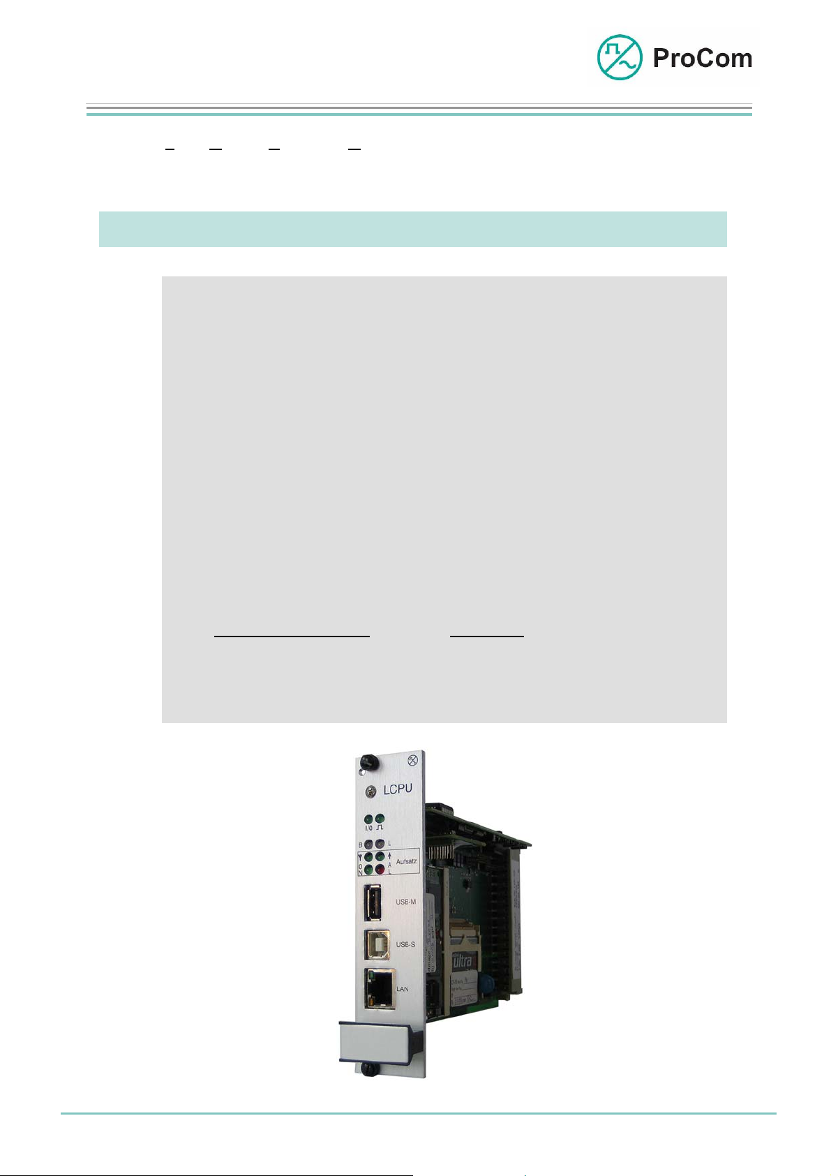
LCPU
Linux IP Attachment
With the Linux Central Processor Unit (LCPU) it is possible to realize public address
announcements from remote locations as well as the networking of systems over the
Internet.
At a Glance:
• DVS-21 system networking over a LAN
• Public address over video workstation
• VoIP connection (according to H323 standard / SIP)
• Digital announcement machine (up to approx. 4000 min.)
• Audio and signal transmitting
• Secure data transmitting
• Standardized interfaces
- 10/100 MBit LAN - USB 1.1 Master - USB 1.1 Slave
• Function expansion through various attachments
Currently available: Optional:
- E1 (2MBit/s) - UART (RS232)
- S0 (Euro-ISDN) - Custom developments
Date:
16.03.2009
Page:
1/5
© 2008 ProCom, All rights and technical changes reserved
Author: HS Document-No.:
DB_LCPU_ 2220_00
Page 2
Data Sheet
LCPU
Linux IP Attachment
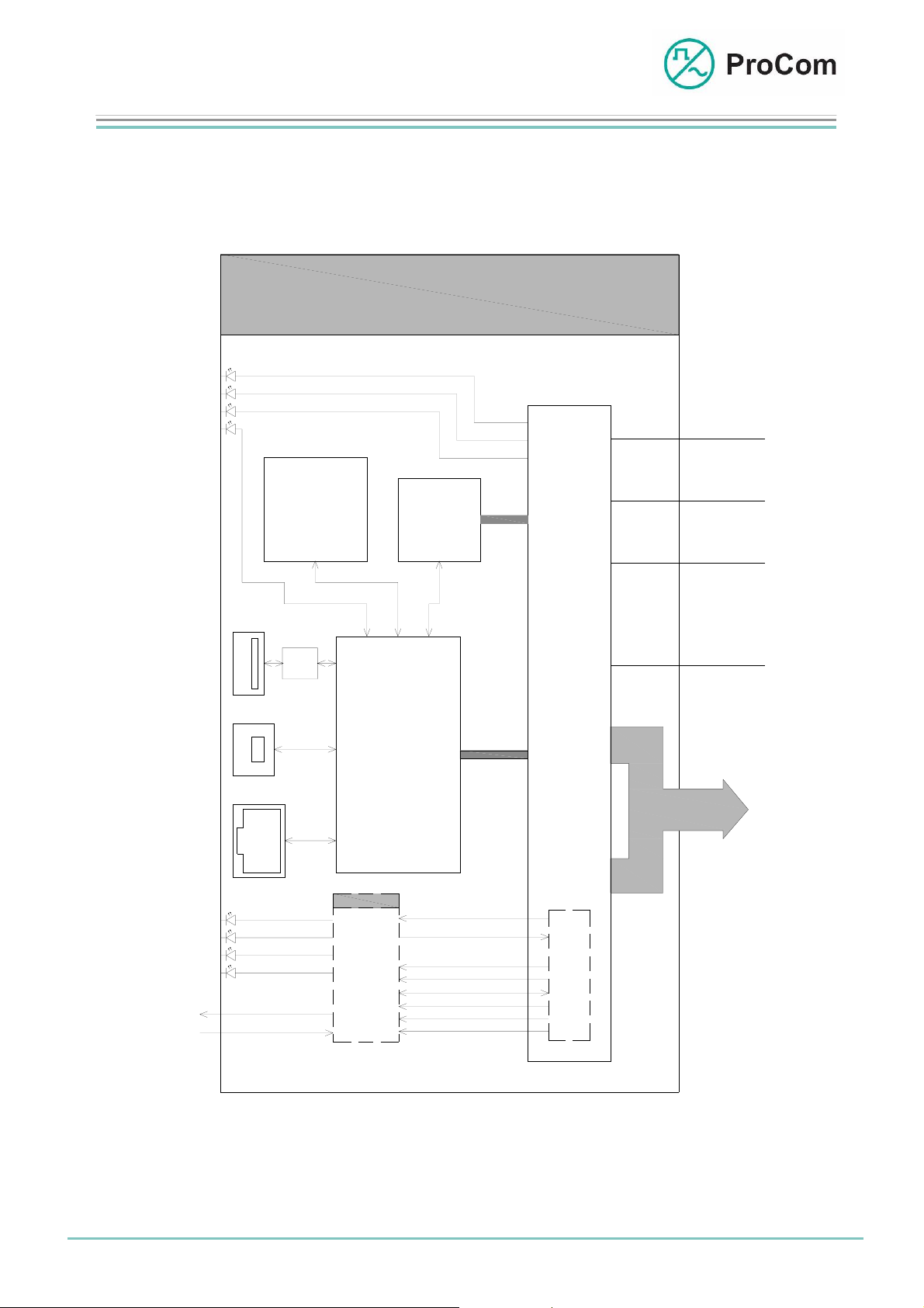
The following block diagram illustrates the functionality of the LCPU:
Fig. LCPU (L- No. 2.220)
LCPU
Statusanzeige
Statusanzeige
Statusanzeige
Statusanzeige
USB
Master
USB
Slave
LAN
Compact
Flash
(bis zu 2 GByte)
USB
Host II
Linux-
CPU
AudioModul
BusCPU
PCM
UART
S
t
e
u
e
r
u
n
g
P
C
+5V
GND
-5V
KS
BUS
Date:
16.03.2009
Aufsatz
Statusanzeige
Statusanzeige
Statusanzeige
Statusanzeige
Tx
Rx
Page:
UART
2/5
© 2008 ProCom, All rights and technical changes reserved
M
STI (Digital Input)
PCM32
STO (Digital Output)
E1/
S0/
FRM
CLK
UART
RST
10MHz
8k
Block diagram LCPU
Author: HS Document-No.:
S
a
t
z
4
DB_LCPU_ 2220_00
Page 3

Data Sheet
LCPU
Linux IP Attachment
The LCPU has a modular structure and consists in the core of
a) The circuit board with the serial and the LAN interface
b) The Linux attachment (mandatory)
c) The BusCPU (soldered on)
d) The audio attachment (slide-in)
e) The compact flash card (CF card)
About a) The circuit board has a multilayer design. The various attachments,
(b – e) are slid in from the top.
The following interfaces are accessible at the front:
- 10/100 Mbit LAN (RJ45)
- USB V1.1 type A (master)
- USB V1.1 type B (slave)
About b) The Linux attachment regulates bus communications. It supports all
features of the Linux kernel 2.6.
Main computer data: XScale PXA 250 with 400 MHz
64 MByte SDRAM (32 bit @ 100 MHz)
32 MByte flash memory (32 bit), expandable to
up to 2 GByte over CF card
About c) The BusCPU is responsible for properly scheduled bus switching for the
DVS-21. Data exchange from and to DVS-21 goes over the PCM bus. A UART
interface works as link between the LCPU and BusCPU.
About d) The audio attachment manages the scheduled control of low frequency
(LF) data received over a LAN over Linux computers to BusCPU and vice
versa.
About e) A compact flash card (up to 2 Gbyte) to save data can be used.
The LCPU can be fitted with an additional attachment. Currently there are three
standard attachments available:
- E1 attachment, L- No. 2.860
- S0 attachment, L- No. 2.870
- UART attachment, L- No. 2.880
The LCPU set 4 is assigned the mode of operation, E1, S0 or UART in the
configuration software ICS depending on the attachment it is equipped with.
The BusCPU on attachment manages communications between the LCPU and
DVS-21.
Date:
16.03.2009
Page:
3/5
© 2008 ProCom, All rights and technical changes reserved
Author:
HS
Document-No.:
DB_LCPU_ 2220_00
Page 4

Data Sheet
LCPU
Linux IP Attachment
Applications:
• Screen (management) workplace
- Public address for remote locations over up to 64 DVS-21 systems
as live public address or through stored text files
- Public address of multiple video workstations to the same
destinations
- Assigning of up to 20 priorities per system
- Configuration also as disruption notification PC
• DVS-21 system networking over a LAN (LCPU to LCPU)
• Digital announcement machine (voice storage function)
• VoIP applications for DVS- 21
• Automatic announcement device / passenger information system
Details can be found in the application descriptions.
The Front Plate Symbols and their Meaning:
The System Blinker
Addressing from processor taking place
I/O Input/Output
BUS output works as push-push operation with the system blinker
BUS input works as push-pull operation with the system blinker
Receiving
Attachment receiving signal (depending on set)
Sending
Attachment sending signal (depending on set)
Date:
16.03.2009
Page:
4/5
© 2008 ProCom, All rights and technical changes reserved
Author:
HS
Document-No.:
DB_LCPU_ 2220_00
Page 5

Data Sheet
LCPU
Linux IP Attachment
Technical Data:
On Status Display
Attachment ready for operation
Al Alarm
Operating Voltage: +/-5 V (control)
Operational Current (+5 V): 200 mA
Operational Current (-5 V): 4 mA
Temperature Range: 0 °C to 45 °C
Weight: 300 g
Installation Height: 3HE
Installation Width: 6TE
Date:
16.03.2009
Page:
5/5
© 2008 ProCom, All rights and technical changes reserved
Author:
HS
Document-No.:
DB_LCPU_ 2220_00
 Loading...