

Page 1

Data Sheet
GG1/GG2/GGS/EG1/EG3
Basis and Expansion Units
The basis and expansion units (GGx and EGx) each consist of a 19 inch module
frame and a backplane.
The backplanes allow a custom, easy and quick installation.
At a Glance:
• D-sub connectors as interface to the outside world
• U-connectors for 6.3 mm flat pin bushing (48 V supply)
• Solder-in bridges for variable, application-specific wiring
⇒ Group assignment for the operating voltage
⇒ Different grounding options
⇒ Phantom power supply for call stations (four-wire
⇒ Disaster function of the V100 amplifier
• Expansion possibility on systems with 28 card slots
technology)
Date:
20.08.2008
Page:
1/5
© 2008 ProCom, All rights and technical changes reserved
Author: HS Document No.:
DB_BPxxx_338x_01
Page 2
Data Sheet
GG1/GG2/GGS/EG1/EG3
Basis and Expansion Units
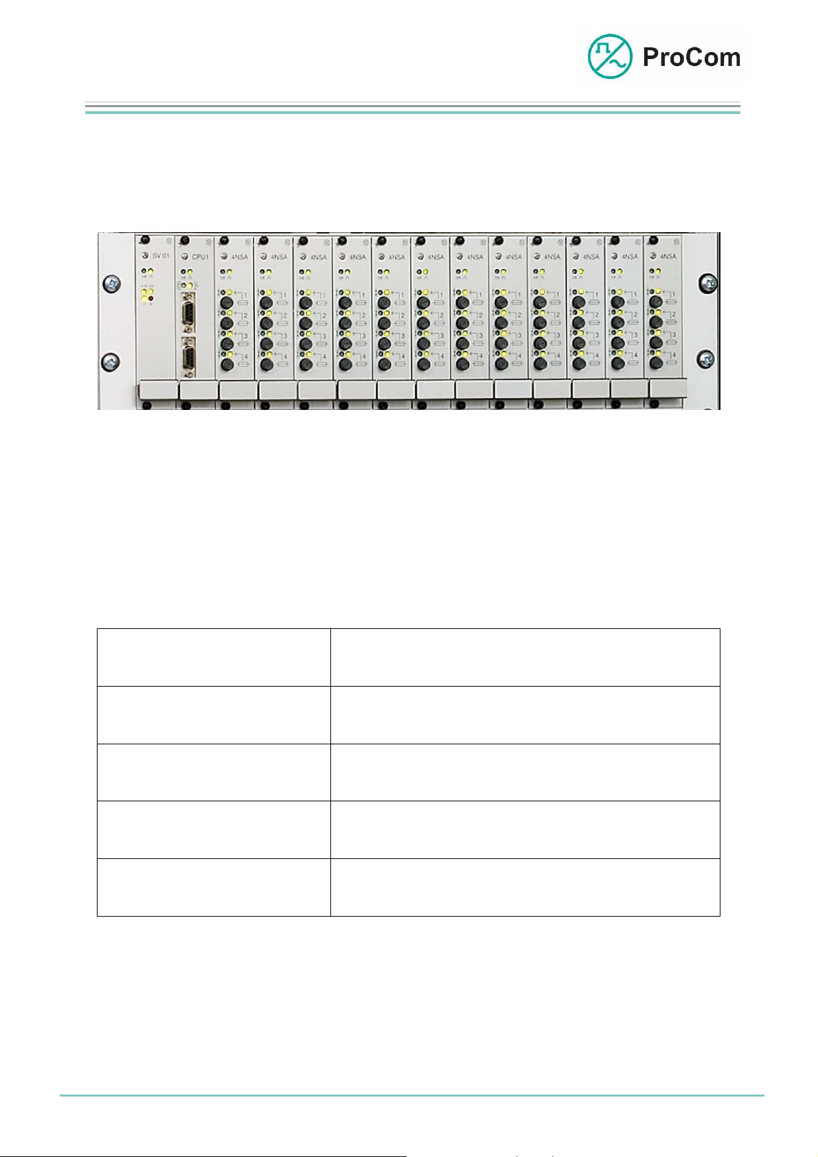
The following picture shows a full GG1 basic unit configured for 48 call stations:
The DVS-21 system consists of a basic unit (GG1, GG2 or GGS) and can be
expanded with the expansion units (EG1 or EG3).
The following table lists the backplanes which are associated with the devices:
GG1: Basic unit 1 BPB12: Basis backplane for CPU1, SV01 and 12
GG2: Basic unit 2 BPB83: Basis backplane for CPU1, SV01,
GGS: Basic unit standby BPS10: Basis backplane for CPU1, SV01,
EG1: Expansion unit 1 BPE14: Expansion backplane for 14 modules
EG3: Expansion unit 3 BPE07: Expansion backplane for 7 modules
Fig. GG1
modules 6TE
6 modules 6TE and 3 modules 12TE
Standby CPU1, standby SV01 and
10 modules 6TE
6TE
12TE
Date:
20.08.2008
Page:
2/5
© 2008 ProCom, All rights and technical changes reserved
Author: HS Document No.:
DB_BPxxx_338x_01
Page 3

Data Sheet
GG1/GG2/GGS/EG1/EG3
Basis and Expansion Units
Fig. BPB12 from the rear
Fig. BPE14 from the
rear
Fi r
g.BPE07 from the rea
Fig. BPB83 from the
rear
he pictures above show the different backplanes and their important connection and
T
modification options.
2 31 4 5 6
8
10 9
Date:
20.08.2008
Page:
3/5
© 2008 ProCom, All rights and technical changes reserved
Author: HS Document No.:
DB_BPxxx_338x_01
Page 4

Data Sheet
GG1/GG2/GGS/EG1/EG3
Basis and Expansion Units
25-pin D-sub connector to connect to the distributor
1
U-connector for 48 V DC operating voltage
2
Solder bridge to distribute the operating voltage 48 V DC
3
Solder bridges for cable screen grounding on the DVS side
4
Solder bridges for additional voltage supply for the call stations
5
with +/-48 V
Connectors to connect an expansion backplane or to take bus
6
termination connectors
9-pin D-Sub connector to connect to the amplifier outlet
7
Solder bridges for disaster allocation
8
Solder bridges for disaster groups
9
Solder bridges for V100 output voltage
10
Technical Data:
Weight: Approx. 2040 g incl. module frame
Installation Height: 3HE (133 mm) incl. module frame
Installation Height: 19 inch (482 mm) incl. module frame
Installation Depth: 240 mm
Date:
20.08.2008
Page:
4/5
© 2008 ProCom, All rights and technical changes reserved
Author: HS Document No.:
DB_BPxxx_338x_01
Page 5

Data Sheet
GG1/GG2/GGS/EG1/EG3
Basis and Expansion Units
Combination Options:
The devices can be combined as follows:
GG1
+
EG1
GG1
+
2 x
EG3
GGS
+
EG1
The connection between the basis units and the expansion units is made with plug-in
ribbon cable.
The system bus must be terminated on the ends with a bus termination connector
with resistance.
GG2
+
EG1
GG2
+
2 x
EG3
GGS
+
2 x
EG3
Date:
20.08.2008
Page:
5/5
© 2008 ProCom, All rights and technical changes reserved
Author: HS Document No.:
DB_BPxxx_338x_01
 Loading...