

Page 1
User Manual
VOR/ILS Analyzer EVS200
0796.1800.02
0798.1988.12-08
Page 2

VOR/ILS Analyzer EVS200
Issue: 01.2002
Version: E8
Copying of this document as well as any other utilization and communication of its content are only admissible
with the permission of the orginator or other authorized persons.
Any disregard will be prosecuted and is subject to restitution (UrhG, UWG, BGB). For the case a patent is
issued or the design is officially registered all rights are reserved.
ROHDE & SCHWARZ GmbH & Co. KG
WerkKöln
D-51147 Köln · Graf-Zeppelin-Straße 18
Telefon: (02203) 49-0 · Int. +49220349-0
Telefax: (02203) 49-51364
Telex: 8874525
Printed in Federal Republic of Germany · Subject to change· Data without tolerances: order of magnitude only
0102
0798.1988.12-08
Page 3

Certificate No.: 0201
This is to certify that
Equipment type: EVS200
Designation: VOR/ILS Analyzer
Order No.: 796.1800.02
EC Certificate of Conf ormity
complies with the provisions of the Directive of the Council of the European Union on the
approximation of the laws of the Member States
− relating to electrical equipment for use within defined voltage limits
(73/23/EEC revised by 93/68/EEC)
− relating to electromagnetic compatibility
(89/336/EEC revised by 91/263/EEC, 92/31/EEC, 93/68/EEC)
Conformity is proven by compliance with the following standards:
− EN61010-1 : 1994 + A2 : 1996 + A2Ber : 1998 + Ber1 : 1998
− EN50081-1 : 1992
− EN50082-1 : 1992
Affixing the EC conformity mark as from 2002-01
ROHDE & SCHWARZ GmbH & Co. KG
Werk Köln
Graf-Zeppelin-Str. 18, D-51147 Cologne
Cologne, 2002-01-17
Quality management 5C-Q / Norres
Page 4

Page 5
Safety Instructions
This unit has been designed and tested in accordance with the EC Certificate of Conformity and has left the
manufacturer’s plant in a condition fully complying with safety standards.
To maintain this condition and to ensure safe operation, the user must observe all instructions and warnings
given in this operating manual.
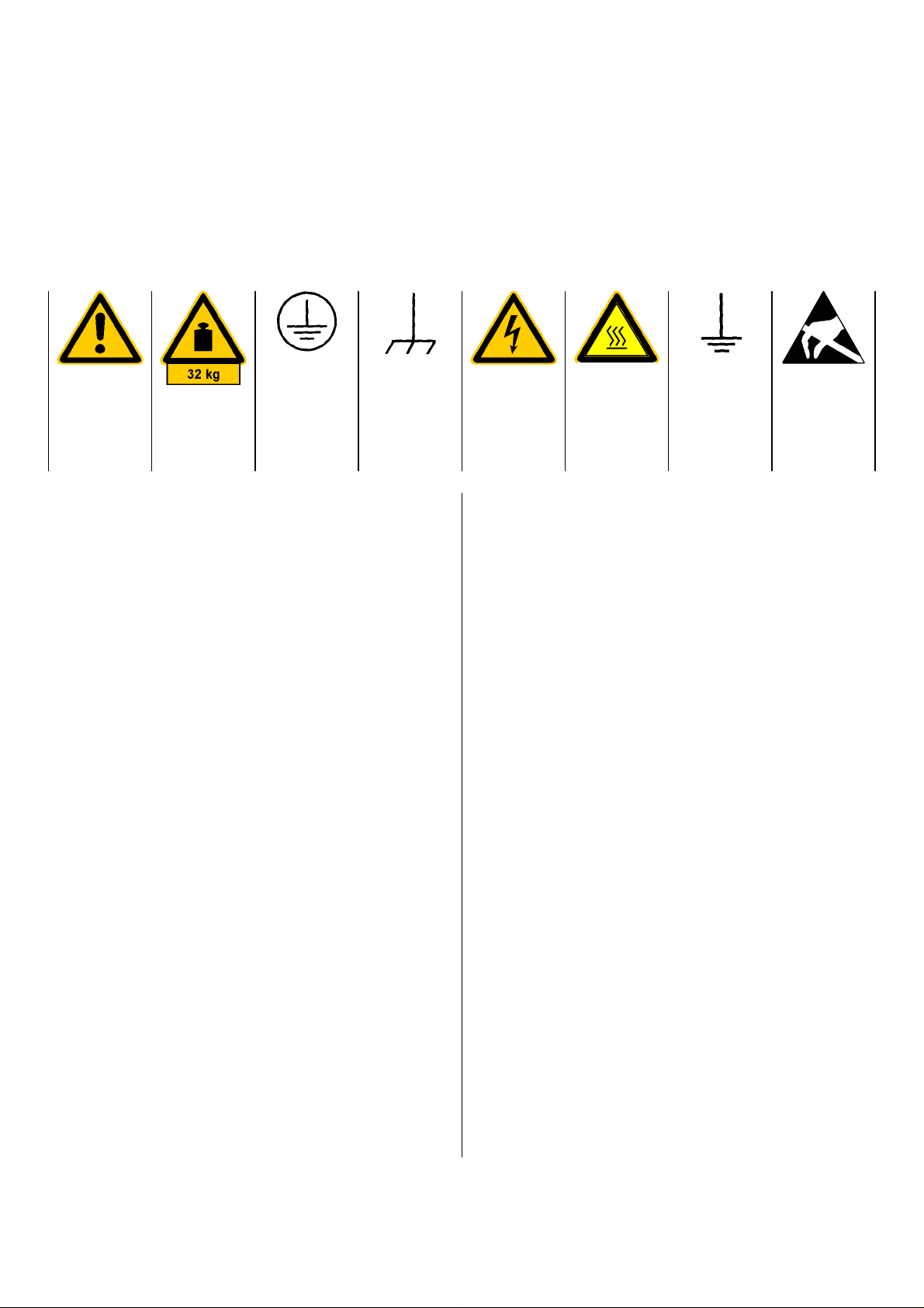
Safety-related symbols used on equipment and documentation from R&S:
Observe
operating
instructions
Weight
indication for
units >18 kg
PE terminal Ground
1. The unit may be used only i n the operating conditions and positions specified by the manufacturer. Unless otherwise agreed, the following
applies to R&S products:
Pollution severity 2, overvoltage category 2, IP
degree of protection 2X, altitude max. 2000 m.
The unit may be operated only from supply networks fused with max. 16 A.
2. For measurements in circuits with voltages V
> 30 V, suitable measures should be taken to
avoid any hazards.
(using, for example, appropriate measuring
equipment, fusing, current limiting, electrical
separation, insulation).
3. If the unit is to be permanently wired, the PE
terminal of the unit must first be connected to
the PE conductor on site before any other connections are made (installation and cabling of
the unit to be performed only by qualified technical personnel).
4. For permanently installed units without built-in
fuses, circuit breakers or similar protective devices, the supply circuit must be fused such as
to provide suitable protection for the users and
equipment.
5. Prior to switching on the unit, it must be ensured
that the nominal voltage set on the unit matches
the nominal voltage of the AC supply network.
If a diff erent voltage is to be set, the power fuse
of the unit may have to be changed accordingly.
6. Units of protection class I with disconnectible
AC supply cable and appliance connector may
be operated only from a power socket with
earthing contact and with the PE conductor connected.
terminal
Danger!
Shock hazard
Warning!
Hot surfaces
Ground
7. It is not permissible to interrupt the PE conductor intentionally, neither in the incoming c able
nor on the unit itself as this may cause the unit
to become electrically hazardous.
Any extension lines or multiple socket outlets
used must be checked for compliance with relevant safety standards at regular intervals.
8. If the unit has no power switch for disconnection
rms
from the AC s upply, the plug of the connecting
cable is regarded as the disconnecting device.
In such cases it must be ensured that the power
plug is easily reachable and accessible at all
times (length of connecting cable approx. 2 m).
Functional or electronic switches are not suitable for providing disconnection from the AC
supply.
If units without power switches are integrated in
racks or systems, a disconnecting device must
be provided at system level.
9. Applicable local or national safety regulations
and rules for the prevention of accidents must
be observed in all work performed.
Prior to performing any work on the unit or
opening the unit, the latter must be disconnected from the supply network.
Any adjustments, replacements of parts, maintenance or repair may be carried out only by
authorized R&S technical personnel.
Only original parts may be used for replacing
parts relevant to safety (eg power switches,
power transformers, fuses). A safety test must
be performed after each replacement of parts
relevant to safety.
(visual inspection, PE conductor test, insulationresistance, leakage-current measurement, functional test).
continued overleaf
Attention!
Electrostatic
sensitive devi-
ces require
special care
095.1000 Sheet 17
Page 6

Safety Instructions
Ensure that the connections with information technology equipment comply with IEC950/EN60950.
11. Lithium batteries must not be exposed to high
temperatures or fire.
Keep batteries away from children.
If the battery is replaced improperly, there is
danger of explosion. Only replace the battery by
R&S type (see spare part list)
Lithium batteries are suitable for environmentally-friendly disposal or specialized recycling. Dispose them into appropriate containers, only.
Do not short-circuit the battery.
12. Equipment returned or sent in f or repair must be
packed in the original packing or in packing with
electrostatic and mechanical protection.
Electrostatics via the connectors may da-
13.
mage the equipment. For the safe handling
and operation of the equipment, appropriate
measures against electrostatics should be implemented.
14. Any additional safety instructions given in this
manual are also to be observed.
095.1000 Sheet 18
Page 7

VOR/ILS Analyzer EVS200
Contents
Contents
Chapter Page
1. Operator Information
- Important operator information 1
- Unpacking 2
- Application of the unit 3
- Characteristics of the unit 4
- Unit l ayout frontview 5
- Unit layout rearview 6
2. Preparation for Operation
- Placing the unit 7
- Mains operation 7
- Mains connection 7
- DC connection 8
- Assembling the FO Cable Jack 8
- Finishing and connection to the Vehicle Board Supply 8
- Connection of Signal/Control Inputs/Outputs 9
- Antenna connection 9
-AFOUT 9
- RS-232-Interface 9
- External AF input 10
- DSP output 10
3. Operation
- Switch On/switch Off the unit at mains supply 11
- Switch On/switch Off the unit at VDC supply 11
- Switchonprocedure 11
- Selftest (BITE) 12
- Battery operation 12
- Operation of the unit 13
- General operating instructions of the VOR/ILS Analyzer EVS200 13
- SETUP-Mode 14
- Operating instructions of SETUP-Mode 15
0796.1800.02 E-8 0.1
Page 8

VOR/ILS Analyzer EVS200
Contents
Chapter Page
- ILS-Mode 16
- Operating instructions of ILS-Mode 16
- Operating instructions of Y / t setup menu 17
- Operating instructions of STORE DDM menu 18
- Signal parameters on ILS Display 20
- VOR-Mode 21
- Operating instructions of VOR-Mode 21
- Signal parameters on VOR Display 22
- BEACON-Mode 23
- Operating instructions of BEACON-Mode 23
- Signal parameters on BEACON Display 24
- ∆∆∆∆ LEVEL-Mode 25
- Operating instructions of ∆ Level-Mode 25
- Storing and recalling reference levels 26
- Signal parameters on ∆ Level Display 28
- SPECTRUM-Mode 29
- Operating instructions of Spectrum-Mode 29
- RS-232-Interface operation 30
- COM-Parameter 30
- Handshake 30
- Control commands 30
- Unit related control commands 31
- Mode related control commands 35
- ILS-Mode 35
- VOR-Mode 44
- ∆ Level-Mode 49
- Beacon-Mode 50
4. Interfaces
- Antenna input 53
- AF output 53
- Headphone connection 53
- XY-Tracer connection 53
- External AF input 54
- RS-232-Interface 54
- External VDC connection 54
- Mains connection 54
0796.1800.02 E-8 0.2
Page 9

VOR/ILS Analyzer EVS200
Contents
Chapter Page
5. Service
- Service 55
- Warranty 55
6. Technical Specification
- Technical data 56
- General data 58
- Accessories 59
0796.1800.02 E-8 0.3
Page 10
VOR/ILS Analyzer EVS200
Important operator information
The symbols used in this description have the following meaning.
Attention: increased vigilance!
Indexfinger: indicates important details
/ Workstep, alphanumeric sequence definition of a workstep!
Chapter 1: Operator Information
Before connecting the unit to a vehicle’s 12-VDC board supply, pay
attention that the battery’s negative pole is connected to ground
(GROUND
Finishing and connection of the auxiliary FO cable jack is
described in chapter „VDC connection" in section 2 "Preparation for
Whilst time of warranty a defective internal battery (option) may
only be changed by Rohde & Schwarz service personnel!
Also after the warranty time it is recommended that
only specialists change the internal battery.
) of the vehicle!
Operating".
0796.1800.02 E-8 1
Page 11
VOR/ILS Analyzer EVS200
Unpacking
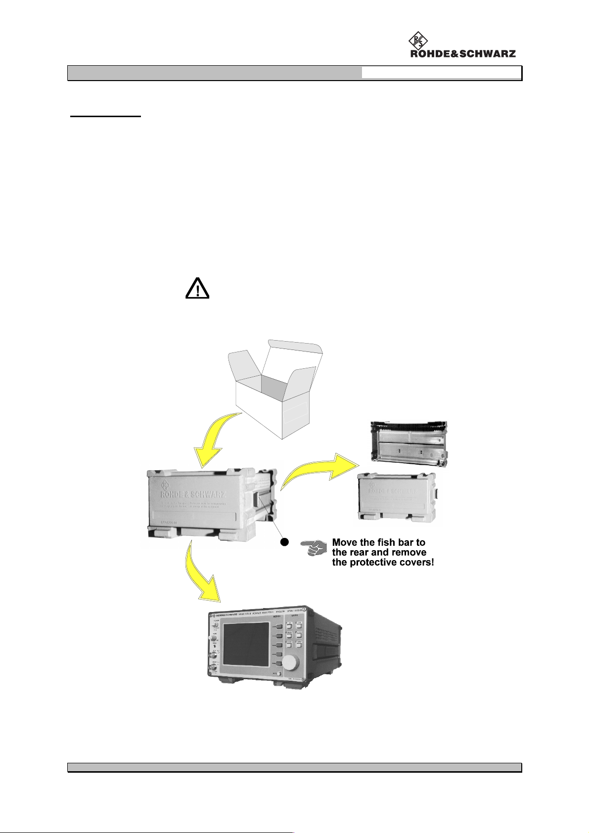
1. Unpack the VOR/ILS Analyzer EVS200.
2. Remove the protective covers.
3. Inspect the unit for evident damage (visual check).
4. Check the auxiliary accessory!
- FO-cabel jack (0018.6700.00)
- power cable
- operating instructions (0798.1988.12-07)
Keep the packing material for reusing!
Chapter 1: Operator Information
0796.1800.02 E-8 2
Page 12

VOR/ILS Analyzer EVS200
Chapter 1: Operator Information
Application of the unit
The VOR/ILS Analyzer EVS200 is used for checking terrestrial radio navigation facilities at airports.
Following components of ILS- and VOR-systems can be checked:
approach to land ILS (Instrument Landing System)
direction localizer LLZ (Localizer) 108 to 118 MHz
glideslope system GS (Glideslope) 320 to 340 MHz
OM (Outer Marker) 75 MHz
MM (Middle Marker) 75 MHz
IM (Inner Marker) 75 MHz
short and medium range navigation
VOR (VHF Omni Range) omnidirectional beacon 108 to 118 MHz
The following measurements can be carried out:
DDM (indication also in 1 / µA / %), SDM, modulation factor
absolute level
delta level (∆ level)
VOR parameter
ILS parameter
75-MHz beacon parameter
Ranges for measurements are e.g:
dynamic runway surveying (limited through high measurement speed
(90 measurements/s))
static distant field surveying
function monitoring of transmitting field stations with data tele-transmitting
surveying of transmitting antenna characteristics through "∆∆∆∆level-mode"
Clearance & Glidepath (common parameter analysis without disconnecting the
transmitting station)
measuring and evaluating of corresponding parameters at high interference intensity
Due to versatile power supply facilities the VOR/ILS Analyzer EVS200 is suitable for operation in field
(battery supply), in vehicles (12-V board supply), and in the lab (AC supply). Among others it is possible to remote control the unit via the RS-232-Interface and recalling all obtained data. Further more
the corresponding parameters of the DSP can be taken at the multifunction output (DSP OUT) for
further analysis (e.g. XY-tracer).
0796.1800.02 E-8 3
Page 13

VOR/ILS Analyzer EVS200
Characteristics of the unit
Remarkable characteristics of the VOR/ILS Analyzer EVS200 are:
high accuracy
easy handling
low power consumption
very compact and light design for mobile operation
battery operation (option) for mobile operation
external DC operation for mobile operation
remote control through RS-232-Interface
selftest facillty (BITE)
Chapter 1: Operator Information
digital signal processing (DSP) on ILS and VOR analysys
high rapidity of measurement (ILS = 90 measurements/s)
immediately display of all measurement data
DDM-/SDM-measurements
calibration of Y / t recorder (DDM = 0)
∆ level measurements (4 reference levels can be stored)
installed loudspeaker and headphone output
suitable for 19" rack assembly
0796.1800.02 E-8 4
Page 14
VOR/ILS Analyzer EVS200
Chapter 1: Operator Information
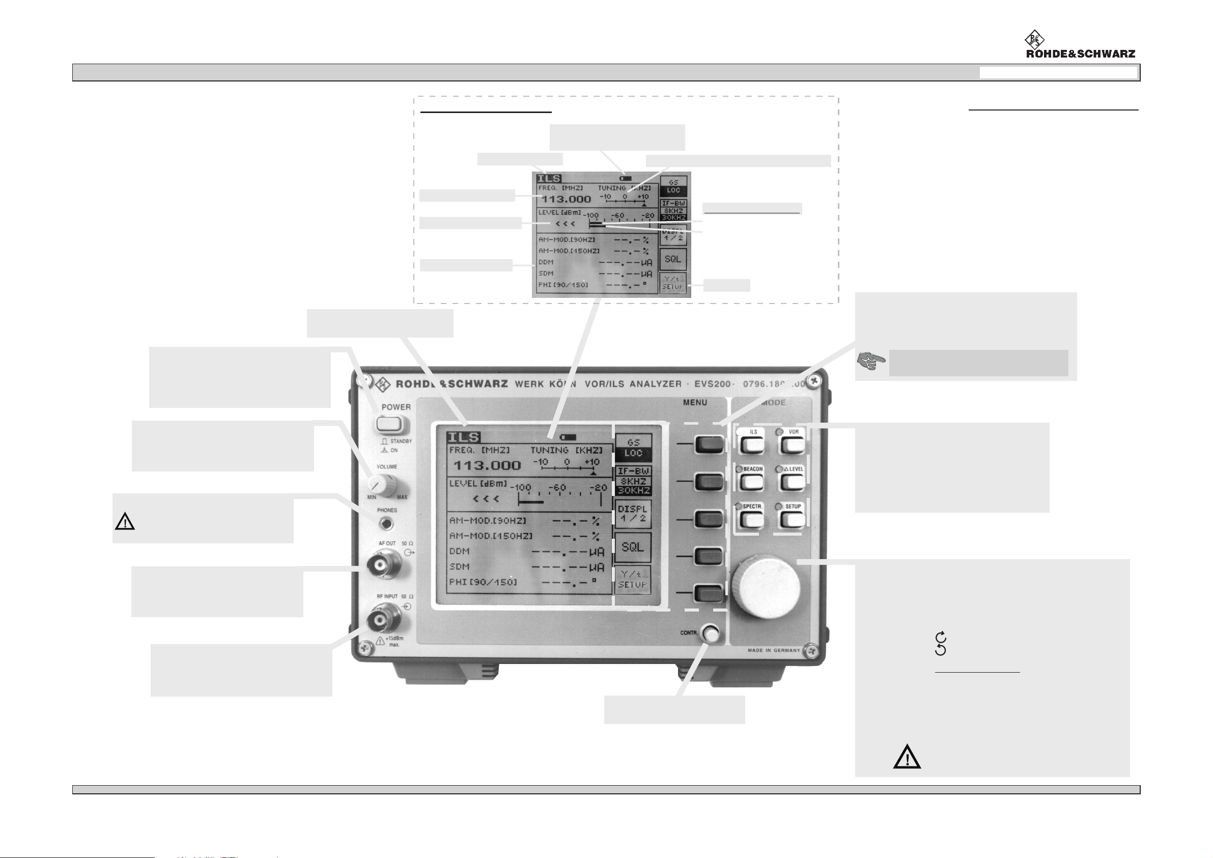
POWER
Set the unit into operation, on mains
supply and in postion "Standby" the
installed battery (Option) will be
charged.
LC display description
receiver frequency
receiver signal level
signal parameters
LC display
(illuminated dot matrix display)
mode indication
Unit layout frontview
battery indication
(only for built-in battery (option))
bargraph center frequency indication
bargraph indication
receiver signal level
squelch threshold
softkeys
Softkeys
Softkeys (program dependent functional keys)
are allocated to the conforming operation mode.
The softkey function is indicated on the display.
On the display all active modes are
sensitive (grey background)!
volume control
With the potentiometer "Volume" the
loudspeaker´s and headphone´s
volume can be set.
headphone connector
only for connecting headphones
with soundproofing!
e.g. R&S order no.0708.9010.00
AF output
BNC socket
output level:
200 mV / 50
by 50 % AM part
rms
antenna input
BNC socket
input level:
VSWR:
max. +15 dBm / 50 Ω
<1.5
mode keys
The mode keys select the corresponding
measurment and setting mode which will
be indicated by the yellow LED.
A selected mode will be indicated on the
display. Mode settings will be performed
with the softkeys.
rollkey
On principle all possible menu settings will be performed
Ω
contrast control
adjustment of display contrast
with the rollkey.
An exception is the "Setup-Menu" where settings must
be performed with the designated softkeys..
turning direction for increasing values
turning direction for decreasing values
frequency setting
The frequency changes depending on the rollkey´s
turning speed in following steps:
- turn rollkey slow 5-kHz-steps
- turn rollkey fast 100-kHz-steps
⇒
(depending upon the setup-settings)
⇒
0796.1800.02
E-8
Rollkey operation is only possible when
function is switched off!"VAR-LOCK"
5
Page 15
VOR/ILS Analyzer EVS200
Chapter 1: Operator Information
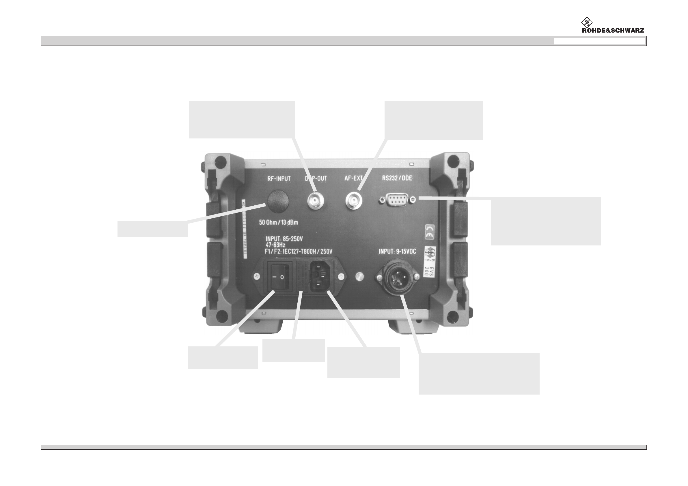
Unit layout rearview
antenna input
not applicable (optional)
DSP output
The scaling of the XY values can be set
in the setup / Y / t setup (ILS mode) for
the and mode.
localizer glideslope
BNC socket
external AF input
The external AF input is to select
in the setup.
BNC socket
input level:
1to2V /50
rms
Ω
RS-232-Interface
SUB-D socket:
COM parameter:
BAUD rate:
9pole
N81
1200, 2400,
4800, 9600,
19200 adjustable in
the setup
0796.1800.02
mains switch
Master switch only
for mains operation
on/off
mains fuses
F1/F2
IEC127-T800H / 250 V
mains connector
socket
87 to 265 VAC
47 to 63 Hz
E-8
external VDC input
When an external VDC supply is connected
the installed battery (option) is switched off.
U 9 to 15 VDC
input
I2A
max
6
Page 16
VOR/ILS Analyzer EVS200
Chapter 2: Preparation for Operation
Preparation for operation
Placing the unit
The VOR/ILS Analyzer EVS200 can be operated in any position without reduction in its function. Even
shocks during normal transportation or on mobile operation don’t reduce its function.
The unit works at ambient temperatures of -5 to +40°C.
Mains operation
Safety Rules
The VOR/ILS Analyzer EVS200 meets the safety rules in ag-
reement with VDE 0411 and VDE 0804 of safety class I. In
agreement with safety class I all mains circuitry must be insulated and the requirement is a good conductive and durable
together and ground wire connection of all touchable, conductive parts of the unit which can directly be alive in case of a
failure.
Mains connector (earthed plug) put only into a protective
contact socket. If there is a connector it must durable be
connected with a ground wire. The ground wire must not
be insulated.
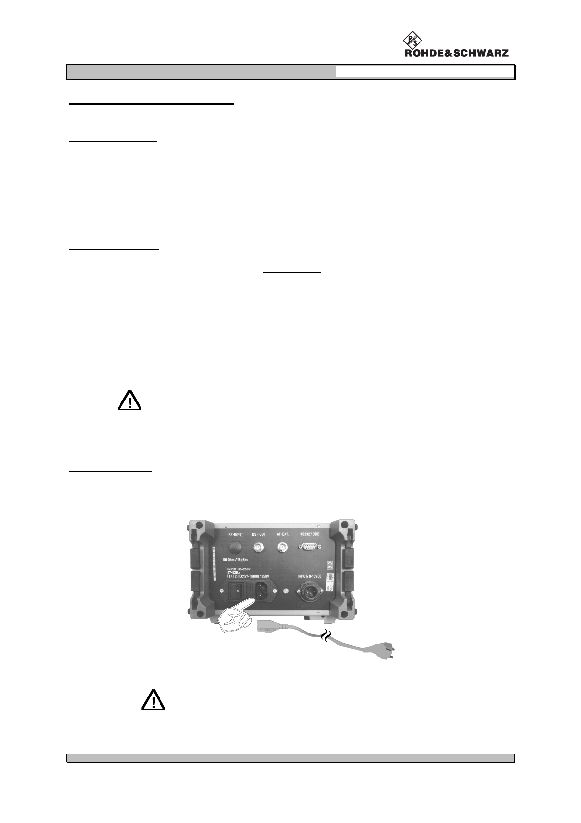
Mains connection
Connect the VOR/ILS Analyzer EVS200 with the supplied power cord to the AC supply
(87 to 265 VAC / 47 to 63 Hz or corresponding to the technical data).
If the unit shall be connected to another AC supply the
corresponding safety rules must be observed!
0796.1800.02 E-8 7
Page 17
VOR/ILS Analyzer EVS200
Chapter 2: Preparation for Operation
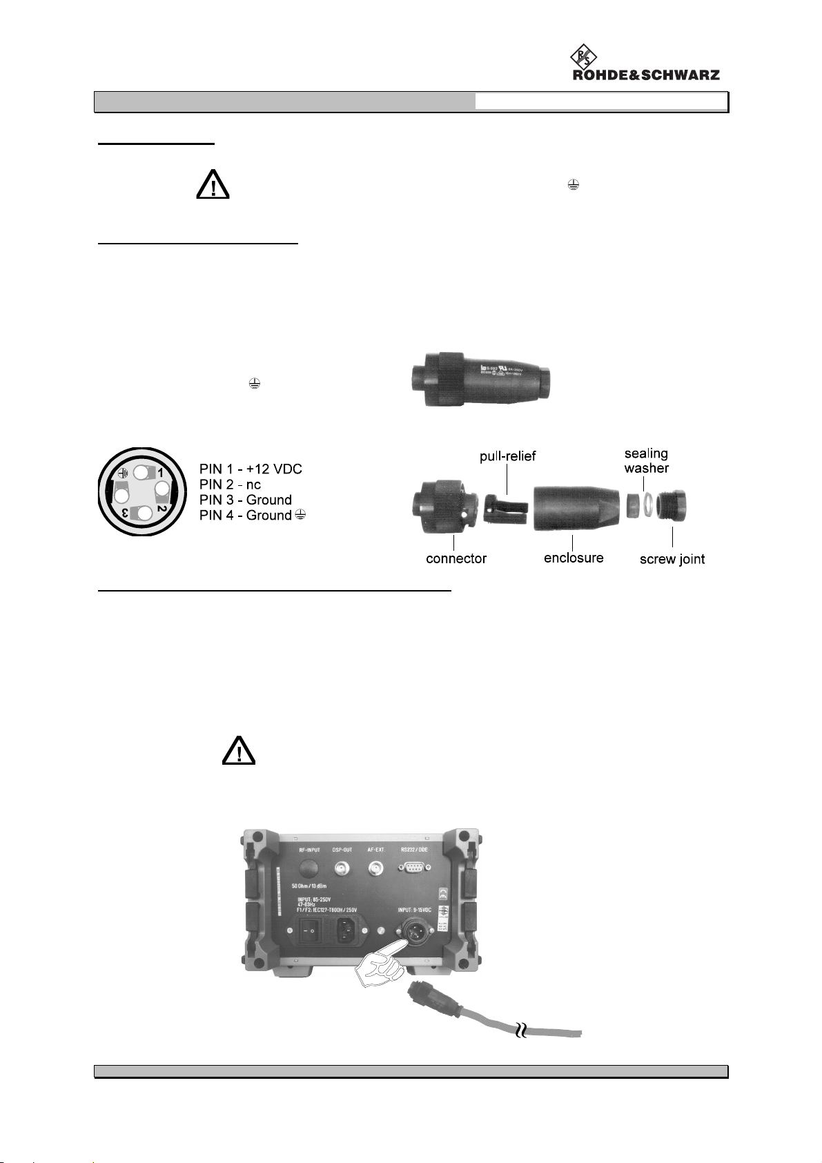
DC connection
Only connect the unit when the minus pole of the battery
is connected to vehicles ground (GROUND
input voltage: 9 to 15 VDC
Assembling the FO Cable Jack
Finish the supplied FO cable jack (0018.6700) as following with commercial PVC cables.
)!
cable specification
PVC wiring performance according VDE 0281
wire cross section 1.0 mm
colour RED for +VDC
colour BLUE for ground(
Pin connection of the FO cable jack Assembling the FO cable jack
Finishing and connection to the Vehicle Board Supply
2
or more
)
FO cable jack
order no.: 0018.6700
Strip the cable end ca. 8mmand mount multicore.
Draw the cable through the enclosure and connect it according to the above pin connection of
the FO cable jack.
Fit the pull-relief and assemble the FO cable jack.
Connect the cable to the vehicle board supply.
When connecting the finished cable to the 12-VDC vehicle
board supply there is to perform a protection by a cable fuse
(T2.0 A) or a fuse on board!
Connect and lock the FO cable jack in the VDC input at the rear of the unit.
0796.1800.02 E-8 8
Page 18
VOR/ILS Analyzer EVS200
Chapter 2: Preparation for Operation
Connection of Signal/Control Inputs/Outputs
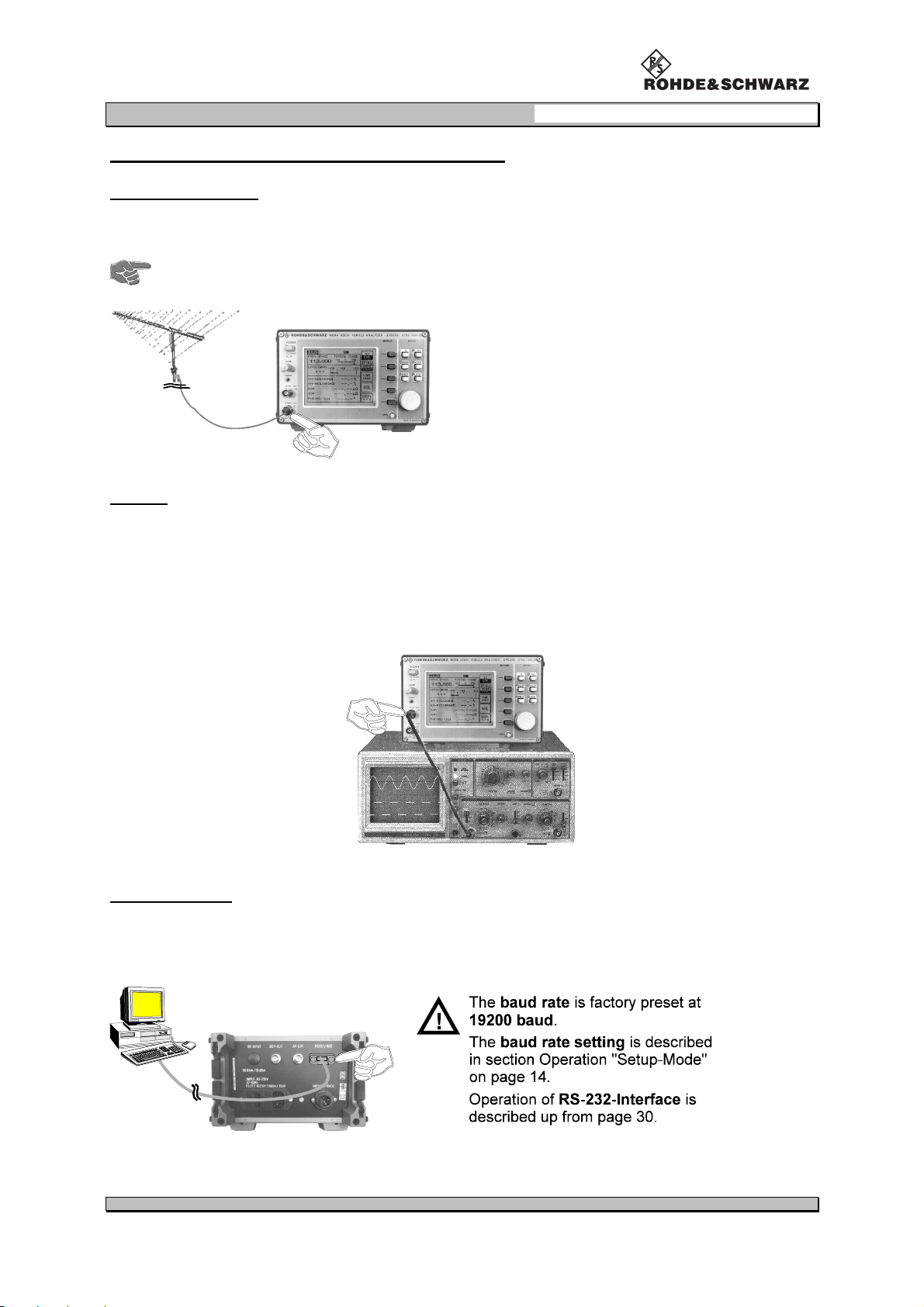
Antenna connection
Via the RF INPUT at the frontside the VOR/ILS Analyzer EVS200 can be connected with a receiver
antenna which agrees to frequency range.
As an option a RF input at the unit’s rear side is possible.
AF OUT
Via the AF OUT at the frontside the demodulated AF signal will be output.
AF signal bandwidth:...............................300 Hz to 4 kHz
output level:.............................approx.: 200 mV
e.g. VOR/ILS Analyzer
RS-232-Interface
Via the RS-232-Interface at the rearside all essential unit functions of the VOR/ILS Analyzer EVS200
can be remote controlled with a PC terminal. For that purpose the unit can be operated with
commercial terminal programs (e.g. Telix, Procomm, etc.)
=oscilloscope
/50Ω / by 50% AM part
rms
0796.1800.02 E-8 9
Page 19
VOR/ILS Analyzer EVS200
Chapter 2: Preparation for Operation
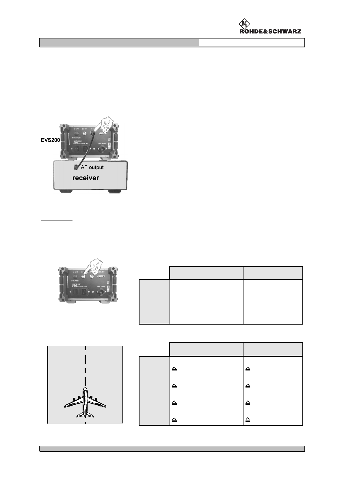
External AF input
Via the AF input (AF-EXT) at the rear side the unit can be fed with an AF signal for further analysis of
typical AF parameters (e.g. level, frequency). This is very applicable for receivers which cannot perform AF analysis.
input level: approx.: 1 to 2 V
e.g. VOR/ILS Analyzer
=external receiver
rms
/50Ω
Connection AF-EXT of the VOR/ILS Analyzer EVS200 with
the AF output of an external receiver
DSP output
On the DSP-OUT at the rearside e.g. a XY-tracer can be connected. The scaling of the XY values
can be set for any mode (localizer/glideslope) in the setup (DDM Y / t-RANGE) or in ILS-Mode
(Y / t-SETUP).
output signals in VOR- and ILS-Mode:
(corresponding
DC voltage)
(0 V ±±±±5mV) 0DDM (1V±±±±5mV)
ILS-Mode VOR-Mode
Display 1
normalized DDM-values
(DC-voltage)
Range1to4
Display 2
voice-frequency
(300 to 3000 Hz)
scaling in the setup:
Localizer Glideslope
Range 1
0.0 ±25%
0 ±0.25 DDM
Range 2
0.0 ±2.5%
0 ±0.025 DDM
Range 3
0.0 ±2.58%
0.0 ±0.0258 DDM
Range 4
0.0 ±50%
0.0 ±0.5 DDM
no output
voice-frequency
(300 to 3000 Hz)
0.0 ±50%
0.0 ±0.5 DDM
0.0 ±5%
0.0 ±0.05 DDM
8.75 ±5%
0.0875 ±0.05 DDM
17.5 +5%
0.175 +0.05 DDM
0796.1800.02 E-8 10
Page 20
VOR/ILS Analyzer EVS200
Operation
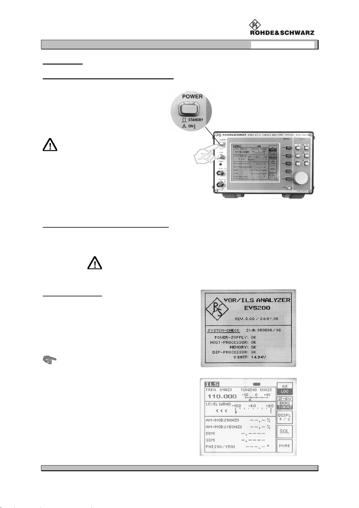
Switch On/switch Off the unit at mains supply
With the mains switch at the rearside
switch the unit on or off.
With the switch "POWER" at the front
side switch the unit on or "STANDBY".
On switch position "STANDBY" the installed battery (option) will be charged.
Details see item "Battery Operation"
(page 12).
Chapter 3: Operation
Switch On/switch Off the unit at VDC supply
When the unit is supplied from the installed battery (option) or through the external DC input it must
be switched on or to "STANDBY" only with the Switch "POWER" at the frontside.
On external DC supply of the unit the installed battery
(option) will not be charged!
Switch on procedure
During the switch on procedure the VOR/ILS
Analyzer EVS200 performs a selftest (BITE). The
tested functions are indicated with "OK". This test
takes approx. 5 s. After that automatically it is
switched over to the startup mode which was set
in the setup.
Because of the displayed battery voltage
(U BATT) it is possible to value the charging
state of the installed battery (option).
ßßßß
Malfunctions of the BITE will be indicated by
"FAIL". In that case the unit does not switch over
to the startup mode (see also item "Selftest").
0796.1800.02 E-8 11
Page 21
VOR/ILS Analyzer EVS200
Selftest (BITE)
Chapter 3: Operation
The selftest checks:
all operating voltages,
host processor,
memory,
DSP processor.
In case of an error the determined functional unit will be indicated with a "FAIL". If the internal
operating voltages totally fail or if they deviate extraordinary from the tolerances a selftest cannot
be carried out.
Error:
In case of an error the unit generally should be
switched off and after a few seconds it schould be
switched on again. If the error message is displayed
again it is recommended to send the unit to the
service, corresponding to Chapter 5 (Service).
Battery operation
The battery operation of the VOR/ILS Analyzer EVS200 is an optional component. It is always possible to retrofit the unit with this mode.
The unit automatically goes into battery operation when the external power supply (DC/AC) is switched
or cut off. The battery operation is indicated on the display by the battery symbol (
) in each mode.
The operation time is >100 minutes (max. brightness) or >150 minutes (at average brightness)
with a completely charged battery.
The charging state can be seen from the battery symbol on the display:
100% battery power
approx. 75 to 25% battery power
flashing symbol, approx. only 5 minutes operation is
ensured. Battery must be charged.
The battery will be charged on AC operation (as well during operation as on "STANDBY") and should
take at least 12 hours (charging time).
After 4 to 5 years or when defect the battery must be
changed according to Chapter 5 "Service".
0796.1800.02 E-8 12
Page 22

VOR/ILS Analyzer EVS200
Chapter 3: Operation
Operation of the unit
Because of the many universal measuring functions of the VOR/ILS Analyzer EVS200 the operation
has to be carried out according to the following instructions. Basically all measurement parameter settings are realized through softkeys and the mode keys. An activated mode is shown by a luminous
LED (beside the belonging mode key). All important signal parameters are analyzed by the DSP (digital
signal processor) and indicated on the display. Due to the variety of the analyzed parameters the indication in the ILS and VOR mode is subdivided into two display parts ("DISPL 1/2" and
DISPL 2/2").
The RS-232-Interface operation of the VOR/ILS Analyzer EVS200 is
described in section "Operating the VOR/ILS ANALYZER EVS200
via RS-232-Interface"
General operating instructions of the VOR/ILS Analyzer EVS200
0796.1800.02 E-8 13
Page 23

VOR/ILS Analyzer EVS200
Chapter 3: Operation
SETUP-Mode
In the following table all possible parameters are listed and its functions are described. Furthermore all
possible setting values per parameter are shown. Next a sequence chart of the operating instructions
in the SETUP mode is following.
Changes in the SETUP can be saved
with the softkey "SAVE".
parameter description setting value
RS232 BAUDRATE baud rate setting 1200, 2400, 4800,
9600, 19200
VOR ANGLE-RESOLUTION BEARING-angle resolution 0,01° / 0,05°
DDM/SDM AVG-FACTOR factor for determining the number of
measurements which form the arithmetical average
DDM Y / t-RANGE [LOC]
DDM Y / t-RANGE [GS]
AF-INPUT-SOURCE AF selection for valuation INT = internal AF
STARTUP mode startup mode setting at switching on the
SQUELCH
XY value scaling in localizer mode at
DSP-OUT (refer to page 10 DSP output)
XY value scaling in glideslope mode at
DSP-OUT (refer to page 10)
unit
on/off switching squelch
1, 2, 4, 8, 16, 32, 64
RNG.1 to RNG.4
RNG.1 to RNG.4
EXT = external AF
via AF-EXT-input
VOR (VOR mode)
ILS (ILS mode)
BCN (Beacon mode)
SPEC (Spectrum mode)
LEVEL (∆
ON / OFF
∆ level mode)
∆∆
setting valid for:
-
∆
level mode
- ILS mode
- VOR mode
When the setting is "ON" an automatical quiet tuning is performed as soon
as the threshold level < the receiver level is.
When setting is "OFF" no quiet tuning will be performed.
DISPLAY ILLUM
DDM/SDM DIMENSIONS value of DDM/SDM indication
DISPLAY-INTERVALL indication interval time
display brightness setting
setting is only valid for display indication
.
OFF ⇐ 1to6Þ MAX
µA/%/1
(1= value without dimension)
1to8
1to 8
approx. 0.4 s to approx. 1.8 s
TUNING-STEP tuning step rate setting 5 / 25 / 50 / 100 (kHz)
0796.1800.02 E-8 14
Page 24

VOR/ILS Analyzer EVS200
Operating instructions of SETUP-Mode
Chapter 3: Operation
0796.1800.02 E-8 15
Page 25

VOR/ILS Analyzer EVS200
ILS-Mode
Operating instructions of ILS-Mode
Chapter 3: Operation
0796.1800.02 E-8 16
Page 26

VOR/ILS Analyzer EVS200
Operating instructions of Y /t setup menu
Chapter 3: Operation
0796.1800.02 E-8 17
Page 27

VOR/ILS Analyzer EVS200
Operating instructions of STORE DDM menu
Chapter 3: Operation
0796.1800.02 E-8 18
Page 28

VOR/ILS Analyzer EVS200
Chapter 3: Operation
0796.1800.02 E-8 19
Page 29

VOR/ILS Analyzer EVS200
Signal parameters on ILS display
Following signal parameters are indicated on the display:
display indication description measuring value
Chapter 3: Operation
DISPL 1/2
FREQ. (MHZ) receiver frequency in MHz (numerical) and
MHz
bargraph center frequency indication in kHz
LEVEL (dBm) receiver signal in dBm (numerical) and
dBm
bargraph indication (the lower bargraph
shows the set squelch threshold)
AM-MOD.(90HZ) AM modulation depth (90 Hz) %
AM-MOD.(150HZ) AM modulation depth (150 Hz) %
DDM differences in depth of modulation DDM-value
(non-dimension value)
µA
%
SDM total modulation factor SDM-value
(non-dimension value)
µA
%
PHI (90/150) phase shift (90 Hz/150 Hz) degree
DISPL 2/2
Y/tSetup
STORE
DDM menu
ID AF-FREQ. AF frequency (1020 Hz) Hz
ID AM-MOD. AMmodulation depth of AF frequency %
VOICE AM-MOD. AM modulation depth in the range of
%
300 to 3000 Hz
Range1to4
XY value scaling in localizer /
%
glideslope mode at DSP-Out.
Locations 1 to 120 DDM/SDM results
0796.1800.02 E-8 20
Page 30

VOR/ILS Analyzer EVS200
VOR-Mode
Operating instructions of VOR-Mode
Chapter 3: Operation
0796.1800.02 E-8 21
Page 31

VOR/ILS Analyzer EVS200
Signal parameters on VOR display
Following signal parameters are indicated on the display:
display indication description measuring value
Chapter 3: Operation
DISPL 1/2
DISPL 2/2
FREQ. (MHZ)
LEVEL (dBm)
BEARING
AM-MOD.(30HZ)
AM-MOD.(9960HZ)
FM-DEVIATION
FM-INDEX
ID AF-FREQ.
ID AM-MOD.
VOICE AM-MOD.
receiver frequency in MHz (numerical) and
bargraph center frequency indication in kHz
receiver signal in dBm (numerical) and
bargraph indication (the lower bargraph
shows the set squelch threshold)
BEARING angle
AM modulation depth (30 Hz)
AM modulation depth (9960 Hz)
frequency deviation
FM index value index value
AF frequency (1020 Hz)
AM modulation depth of AF frequency
AM modulation depth in the range of
300 to 3000 Hz
MHz
dBm
DEG
%
%
Hz
(non-dimension value)
Hz
%
%
0796.1800.02 E-8 22
Page 32

VOR/ILS Analyzer EVS200
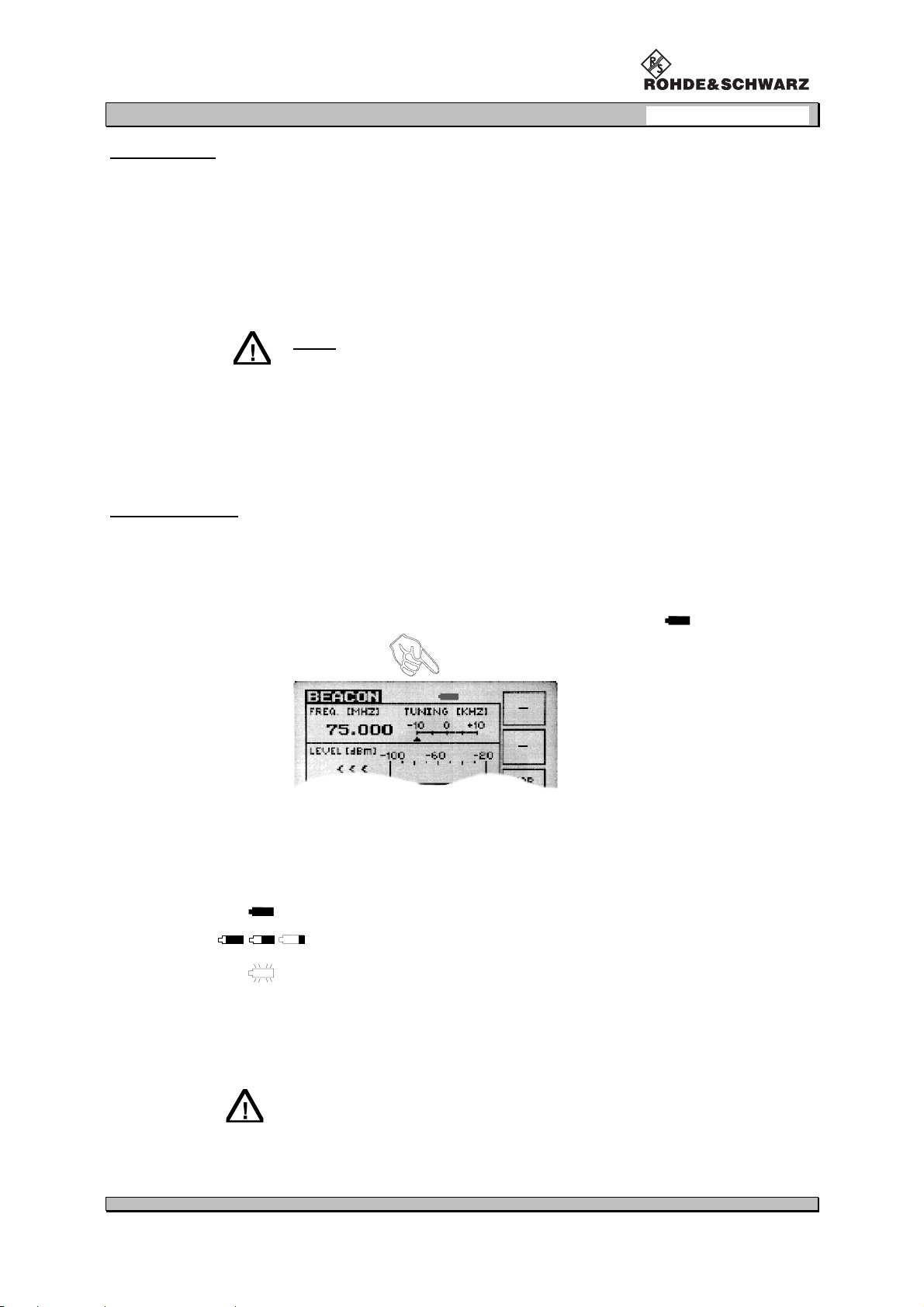
BEACON-Mode
Operating instructions of BEACON-Mode
Chapter 3: Operation
0796.1800.02 E-8 23
Page 33

VOR/ILS Analyzer EVS200
Signal parameters on BEACON display
Following signal parameters are indicated on the display:
display indication description measuring value
Chapter 3: Operation
FREQ. (MHZ)
LEVEL (dBm)
F1
F2
F3
ID
receiver frequency in MHz (numerical) and
bargraph center frequency indication in kHz
receiver signal in dBm (numerical) and
bargraph indication (the lower bargraph
shows the set squelch threshold)
AF frequency and AM modulation depth at
3000 Hz (inner marker)
AF frequency and AM modulation depth at
1300 Hz (middle marker)
AF frequency and AM modulation depth at
400 Hz (outer marker)
AF frequency and AM modulation depth of
the identifier
MHz
dBm
Hz and %
Hz and %
Hz and %
Hz and %
0796.1800.02 E-8 24
Page 34

VOR/ILS Analyzer EVS200
∆∆∆∆ Level-Mode
Operating instructions of ∆∆∆∆ Level-Mode
Chapter 3: Operation
0796.1800.02 E-8 25
Page 35

VOR/ILS Analyzer EVS200
Chapter 3: Operation
Storing and recalling reference levels
To occupy storage capacaty or to call up memory the ∆∆∆∆ level mode has a storage menu which will be
called up by pushing the softkey "MEM".
Until four memory blocks M1 to M4 can be stored or called up. Following data will be allocated to a
storage space:
- actual reference level,
- actual receiver frequency.
After storing or recalling of a memory the ∆∆∆∆ level main window is updated with the relevant memory
data. When the receiving level changes the update ∆ level is permanently indicated in ∆∆∆∆ level window.
Storage menu explanation:
See next page for t he operation diagram for "Storing Reference Levels" and
"Recalling Single Memory".
0796.1800.02 E-8 26
Page 36

VOR/ILS Analyzer EVS200
Chapter 3: Operation
0796.1800.02 E-8 27
Page 37

VOR/ILS Analyzer EVS200
Signal parameters on ∆∆∆∆ Level Display
Following signal parameters are indicated on the display::
display indication description measuring value
Chapter 3: Operation
FREQ. (MHZ)
LEVEL (dBm)
∆ LEVEL (dB) actual ∆ level (difference between actual
LEVEL REF.
receiver frequency in MHz (numerical) and
bargraph center frequency indication in kHz
receiver signal in dBm (numerical) and
bargraph indication (the lower bargraph
shows the set squelch threshold)
receiving level and set reference level)
the bargraph indication shows the ∆ level
as a tendency indication
set reference level
MHz
dBm
dB
dBm
0796.1800.02 E-8 28
Page 38

VOR/ILS Analyzer EVS200
Spectrum-Mode
Operating instructions of Spectrum-Mode
The spectrum analysis of the VOR/ILS Analyzer EVS200 is
only for trend indication in the scanned range.
Chapter 3: Operation
0796.1800.02 E-8 29
Page 39

VOR/ILS Analyzer EVS200
Chapter 3: Operation
RS-232-Interface operation
All important unit functions can be remote controlled via the RS-232-Interface (V24 standard) by a PC
terminal which can be operated with commercial terminal programs (e.g. Telix, Procomm...). AS a data
terminal (DDE) the VOR/ILS Analyzer EVS200 must be connected with a RS-232-1:1-Interface.Also
it is possible to control the unit with an user defined program. The necessary commands for that purpose are described below.
COM-Parameter
The com parameters parity,number of data bits, and stop bits cannot be changed and are defined as
"firmware“.
non parity bit (N),
8 data bits (8),
1stopbit (1).
Handshake
Hardware handshake is renounced.
Handshake is performed by software as a transmitted sequence e.g. "READY“ or as a measuring
value or a tuning value e.g. "RF107000“.
Control commands
There are two categories of control commands.
super commands (mode independant, unit related)
mode dependant commands (specified mode must first be selected)
The following table makes clear the control commands structure.
unit related
control commands
BI
EC0
EC1
LA
LO
MB
MI
ML
MV
RES
RF(Freq. kHz)
RF
TEST
VER
ILS-Mode VOR-Mode
AF8
AM2
AM3
AM8
AM9
BW0
BW1
D1
D2
DD0
DD1
FA0
FA1
FA2
FA3
PH
SD0
SD1
mode dependant control commands
∆∆∆∆ Level-Mode
AF8
AM0
AM1
AM8
AM9
BE
D1
D2
FA0
FA2
FA3
FM0
FM1
BW0
BW1
LR
LD
SR
BEACON-
Mode
AF4
AF5
AF6
AF7
AM4
AM5
AM6
AM7
0796.1800.02 E-8 30
Page 40

VOR/ILS Analyzer EVS200
Chapter 3: Operation
Unit related control commands
Command RF (frequency in kHz)
command function
RF (frequency in kHz) <frequency information> setting or scanning receiving frequency
With the command RF (frequency in kHz) a frequency input is possible in the ranges of 107000 to
119000 kHz and 319000 to 341000 kHz. With this command it is also possible to scan the tuned
frequency when the command RF is transmitted to the EVS200 without additionally parameters. The
unit responses with the frequency information.
Example:
command from the controller
response of the VOR/ILS Analyzer EVS200
input:
query:
RF107000 <CR>
rf107000 <CR>
RF<CR>
rf<CR>
READY <CR/LF>
READY <CR/LF>
107000kHz <CR/LF>
107000kHz <CR/LF>
Command LO
command function
LO <Local> set unit local mode
Because local operation is automatically locked when the unit is controlled by a controller, the command LO (local) performs further local operation at the unit.
Example:
input:
command from the controller
LO<CR>
lo<CR>
response of the VOR/ILS Analyzer EVS200
READY <CR/LF>
READY <CR/LF>
Command EC0
command function
EC0 <echo off > selection of communication
EVS200 does not retransmit the received control string.
Example:
command from the controller
query:
0796.1800.02 E-8 31
EC0 <CR>
ec0 <CR>
response of the VOR/ILS Analyzer EVS200
READY <CR/LF>
READY <CR/LF>
Page 41

VOR/ILS Analyzer EVS200
Chapter 3: Operation
Command EC1
command function
EC1 <echoon> selection of communication
EVS200 retransmits the received control string.
Example:
command from the controller
response of the VOR/ILS Analyzer EVS200
query:
EC1 <CR>
ec1 <CR>
READY <CR/LF>
READY <CR/LF>
Command test
command function
TEST < > RS232 test section output
The command TEST initiates a RS232 test section. All ASCII characters 20h to FF will be supplied.
Example:
response of the VOR/ILS Analyzer EVS200
READY <CR/LF>
READY <CR/LF>
query:
command from the controller
EC1 <CR>
ec1 <CR>
Command LA
command function
LA <Level Absolute> query of receiving level
The command LA reads the actual receiving signal level in "∆∆∆∆ Level"-mode.
Example:
command from the controller
query:
0796.1800.02 E-8 32
LA <CR>
la <CR>
response of the VOR/ILS Analyzer EVS200
e.g. -48.1dBm <CR/LF>
e.g. -48.1dBm <CR/LF>
Page 42

VOR/ILS Analyzer EVS200
Chapter 3: Operation
Command RES
command function
RES <RESET> Master-RESET
With the command RES a unit master reset is possible. It works like a restart of the unit.
Example:
command from the controller response of the VOR/ILS Analyzer EVS200
input:
RES<CR>
res<CR>
EVS200 REMOTE-SYSTEM READY <CR/LF>
READY <CR/LF>
READY <CR/LF>
Command BI
command function
BI <BITE-test information> BITE (Build In Test) -asking for result
The EVS200 performs approx. every 500 ms a self test (BITE) and makes the result available as a
9bit binary form. During this test the following voltages and funtionally subunits of the units are
checked.
all operating voltages,
hostprocessor
memory,
DSP-processor,
battery capacity (%)
explanation of BITE information
B8 B7 B6 B5 B4 B3 B2 B1 B0
SYNTH 1 SYNTH 2 EXT-DC PS-DC +12 VDC -12 VDC Batt2 Batt1 Batt0
XXXXXXXXX
X = 1 is function in tolerance (ok)
X = 0 is function out of tolerance (failure)
Example:
command from the controller
query:
0796.1800.02 E-8 33
BI <CR> BI110111101 <CR/LF>
response of the VOR/ILS Analyzer EVS200
Page 43

VOR/ILS Analyzer EVS200
Chapter 3: Operation
Command VER
command function
VER <Version> query of version number and date of the
EVS200 firmware
The command VER initializes the display of the software version number and its issue date.
Example:
command from the controller
response of the VOR/ILS Analyzer EVS200
query:
VER <CR>
ver <CR>
EVS200 - VERSION < No. > from < Date >
Copyright (C) Rohde & Schwarz Werk Köln
<CR/LF>
Command ML
command function
ML <Mode-Delta Level>
The command ML enables a switching over to the "∆∆∆∆ level" mode.
Exampel:
command from the controller
input:
ML <CR>
ml <CR>
∆∆∆∆ level mode setting
response of the VOR/ILS Analyzer EVS200
READY <CR/LF>
READY <CR/LF>
Command MV
command function
MV <Mode-VOR> VOR mode setting
The command MV enables a switching over to the "VOR“ mode.
Example:
command from the controller response of the VOR/ILS Analyzer EVS200
input:
0796.1800.02 E-8 34
MV <CR>
mv <CR>
READY <CR/LF>
READY <CR/LF>
Page 44

VOR/ILS Analyzer EVS200
Command MI
command function
MI <Mode-ILS> ILS mode setting
The command MI enables the switching over to the "ILS“ mode.
Example:
command from the controller response of the VOR/ILS Analyzer EVS200
Chapter 3: Operation
input:
MI <CR>
mi <CR>
READY <CR/LF>
READY <CR/LF>
Command MB
command function
MB <Mode-BEACON> BEACON mode setting
The command MB enables the switching over to the "BEACON mode“.
Example:
command from the controller response of the VOR/ILS Analyzer EVS200
input:
MB <CR>
mb <CR>
READY <CR/LF>
READY <CR/LF>
Mode related control commands
ILS-Mode
Command DD0
command function
DD0 <DDM information> DDM value query
The command DD0 reads the actual DDM value (value without dimension) in the ILS mode.
Example:
command from the controller
query:
0796.1800.02 E-8 35
DD0 <CR>
dd0 <CR>
response of the VOR/ILS Analyzer EVS200
e.g. 0.2008 <CR/LF>
e.g. 0.2008 <CR/LF>
Page 45

VOR/ILS Analyzer EVS200
Command DD1
command function
Chapter 3: Operation
DD1 <DDM information>
The command DD1 reads the actual DDM value in µA in the ILS mode.
Example:
command from the controller
query:
DD1 <CR>
dd1 <CR>
query of the DDM value in µµµµA
response of the VOR/ILS Analyzer EVS200
e.g. 194.32uA <CR/LF>
e.g. 194.32uA <CR/LF>
Command SD0
command function
SD0 <SDM information> SDM value query
The command SD0 reads the actual SDM value (value without dimension) in the ILS mode.
Example:
command from the controller
response of the VOR/ILS Analyzer EVS200
query:
SD0 <CR>
sd0 <CR>
e.g. 0.8006 <CR/LF>
e.g. 0.8006 <CR/LF>
Command SD1
Command function
SD1 <SDM information>
The command SD1 reads the actual DDM value in µA in the ILS mode.
Example:
command from the controller
query:
SD1 <CR>
sd1 <CR>
query of SDM value in µµµµA
response of the VOR/ILS Analyzer EVS200
e.g. 774.87uA <CR/LF>
e.g. 774.87uA <CR/LF>
0796.1800.02 E-8 36
Page 46

VOR/ILS Analyzer EVS200
Chapter 3: Operation
Command AM2
command function
AM2 <AM modulation depth (90 Hz)> query of AM modulation depth (90 Hz)
The command AM2 reads the actual AM modulation depth (90 Hz) in the ILS mode.
Example:
command from the controller
response of the VOR/ILS Analyzer EVS200
query:
AM2 <CR>
am2 <CR>
e.g. 50% <CR/LF>
e.g. 50% <CR/LF>
Command AM3
command function
AM3 <AM modulation depth (150 Hz)> query of AM modulation depth (150 Hz)
The command AM3 reads the actual AM modulation depth (150 Hz) in the ILS mode.
Example:
response of the VOR/ILS Analyzer EVS200
e.g. 29.9% <CR/LF>
e.g. 29.9% <CR/LF>
Query:
command from the controller
AM3 <CR>
am3 <CR>
Command PH
command function
PH <Phase 90/150 Hz> query of Phase angle 90/150 Hz
The command PH reads the actual PHI value between 90 Hz and 150 Hz in the ILS mode.
Example:
command from the controller
query:
0796.1800.02 E-8 37
PH <CR>
ph <CR>
response of the VOR/ILS Analyzer EVS200
e.g. 119.9DEG <CR/LF>
e.g. 119.9DEG <CR/LF>
Page 47

VOR/ILS Analyzer EVS200
Chapter 3: Operation
Command BW0
command function
BW0 <bandwidth information > 8-kHz bandwidth setting
The command BW0 enables the switching over to the 8-kHz bandwidth in the ILS mode and in the
"∆∆∆∆ level" mode.
Example:
command from the controller
response of the VOR/ILS Analyzer EVS200
input:
BW0 <CR>
bw0 <CR>
READY <CR/LF>
READY <CR/LF>
Command BW1
command function
BW1 <bandwidth information> 30-kHz bandwidth setting
The command BW1 enables the switching over to the 30-kHz-IF bandwidth in the ILS mode and in
the "∆∆∆∆ level" mode.
Example:
input:
command from the controller
BW1 <CR>
bw1 <CR>
response of the VOR/ILS Analyzer EVS200
READY <CR/LF>
READY <CR/LF>
0796.1800.02 E-8 38
Page 48

VOR/ILS Analyzer EVS200
o
d
Chapter 3: Operation
Command FA1
command function
FA1 <Fast DDM measuring on> Activating the Fast DDM measurement
The command FA1 switches on the fast DDM measurement. The measuring, used only for landing
path measurement can only be activated through a controller. The output is performed as DDM value
with RF level (see example) and can be processed accordingly with calculation programs e.g. like
Excel etc. A capacaty of 34 measurements /s at a baud rate set to 19200 baud will be reached. This
conforms to a time interval of 30 ms. The measurement values (DDM, RF level) can be read in and
output as a text file corresponding to the terminal program.
To reach 34 meas/s the baud rate must be set to 19200 baud in the Setup of the
VOR/ILS Analyzer EVS200. It must be attended the acceptance of the data transfering
rate by the terminal program.
Example:
The measurement can be stopped through the command FA0 (refer to Command
FA0).
command from the controller
response of the VOR/ILS Analyzer EVS200
input: FA1 <CR>
fa1 <CR>
With the command FA1 the ech
mode is automatically switche
OFF.
1/90Hz = 11.1msec.
N N+1 N+2 N+3 N+4 N+5 N+6 N+7 N+8 N+9 N+10
DATA-
Transfer
DDM, RF-Level
Calculation
RS232-
Transfer
N
DATA-
0.2008 -48.2 <CR/LF>
0.2008 -48.2 <CR/LF>
Both values are separated through a tabulator
ASCII 9.
RS232-
DDM, RF-Level
Calculation
30 msec.
DATA-
TransferTransfer
N+2 N+5
DDM, RF-Level
Calculation
RS232-
TransferTransfer
DATA-
Transfer
DSP-Analysis
TXD-Signal
from EVS 200
0796.1800.02 E-8 39
Page 49

VOR/ILS Analyzer EVS200
o
d
:
µ
:
:
:
Chapter 3: Operation
Command FA2
command function
FA2 <Fast DDM measuring on> Activating the Fast DDM measurement
The command FA2 switches on the fast DDM measurement. The measuring, used only for landing
path measurement can only be activated through a controller.
The command FA2 performs the continuous measurement and output of the DDM, RF level, Modfactor 90 Hz and Modfactor 150 Hz with a transmission speed of about 20 measurement value sets
(DDM, RF level, AM90, AM150) per second. This conforms to a time interval of 50 ms. The stated
RS-232-transmission times are related to 19.200 Baud.
The measurement values can be read in and output as a text file corresponding to the terminal program.
To reach 20 meas/s the baud rate must be set to 19200 baud in the Setup of the
VOR/ILS Analyzer EVS200. It must be attended the acceptance of the data transfering
rate by the terminal program.
Example:
The measurement can be stopped through the command FA0 (refer to Command
FA0).
command from the controller
response of the VOR/ILS Analyzer EVS200
input: FA2 <CR>
fa2 <CR>
With the command FA2 the ech
mode is automatically switche
OFF.
1/90Hz = 11.1msec.
N N+1 N+2 N+3 N+4 N+5 N+6 N+7 N+8 N+9 N+10
DATA-Transfer
DDM, AM 90, AM150,
RF-Level - Calculation
output form: (DDM <CR >, RF level <CR >,
AM90 <CR >, AM 150 <CR >)
DDM: four-digit with indication (dimensionless)
example
five-digit with indication (
example
-1000 <CR > (-0.1000 DDM)
A)
-09890 <CR > (-98.90µA)
RF level: three-digit with indication (dBm)
example
-400 <CR > (-40.0dBm)
122 <CR > (12.2dBm)
Modulation depth: three-digit (%)
example
202 <CR > (20.2 %)
004 <CR > (0.4 %)
RS232Transfer
DA T A-Transfe r
DDM, AM 90, AM150,
RF-Level - Calculation
RS232-
Transfer
DA T A-Transfe r
DSP-Analysis
NN+4
40 msec. 10 msec.
TXD-Signal
from EVS 200
0796.1800.02 E-8 40
Page 50

VOR/ILS Analyzer EVS200
o
d
D
Chapter 3: Operation
Command FA3
command function
FA3 <Fast DDM measuring on> Activating the Fast DDM measurement
The command FA3 switches on the fast DDM measurement. The measuring, used only for landing
path measurement can only be activated through a controller. The command FA3 performs the continuous measurement and output of the DDM, RF level, Modfactor 90 Hz and Modfactor 150 Hz.
The 50-ms measurement interval consists of DSP analysis, DSP data transmission to the host
processor and conversion of the DSP raw measurement value into DDM, dBm and AM %. The
measurement values output is performed in this mode as interrupt operation via RS232 interface.
In this Fast-Mode (FA3) a measurement value set will only be transmitted to the PC if it is demanded
by a short command (1 ASCII-Character). The response from the EVS200 is performed without a
longer delay within about 15 to 20 ms between measurement value demand and measurement
value transmission. The stated RS-232-transmission times are related to 19.200 Baud.
The measurement values can be read in and output as a text file corresponding to the terminal program.
The baud rate must be set to 19200 baud in the Setup of the VOR/ILS Analyzer
EVS200. It must be attended the acceptance of the data transfering rate by the
terminal program.
The measurement can be stopped through the command FA0 (refer to Command
FA0) or
<CR>.
Example:
command from the controller
input: e.g. A
all ASCII characters without:
CR (0Dh), LF (0Ah), # (23h), @ (40h)
With the command FA3 the ech
mode is automatically switche
OFF.
1/90Hz = 11.1msec.
N N+1 N+2 N+3 N+4 N+5 N+6 N+7 N+8 N+9 N+10
Demand for measurement
values output:
DATA-Transfer
DDM, AM 90, AM150,
RF-Level - Calculation
response of the VOR/ILS Analyzer EVS200
output form: (DDM <CR >, RF level <CR >,
AM90 <CR >, AM 150 <CR >)
output form as FA2
example: -0001 <CR > (DDM),
-412 <CR > (RF level),
201 <CR > (AM90),
202 <CR > (AM150),
Programm-Interrupt
DATA-Transfer
DDM, AM90, AM150,
RF-Level - Calculation
DDM, AM90, AM150,
RF-Level - Calculation
RS232Transfer
15...20 m s ec.
DATA-Transfer
DSP-Analysis
Request from PCl
to EVS200 (RXD)
N
10 msec.
0796.1800.02 E-8 41
Answer to PCl
fromEVS200 (TX
Page 51

VOR/ILS Analyzer EVS200
Chapter 3: Operation
Command FA0
command function
FA0 <fast DDM measuring off> deactivating the fast DDM measurement
The command FA0 switches off the fast DDM measurement.
Example:
command from the controller
response of the VOR/ILS Analyzer EVS200
input:
FA0 <CR>
fa0 <CR>
READY <CR/LF>
READY <CR/LF>
Command D1
command function
D1 <display information> switch over to display1
The command D1 enables the switching over to the content of display1 in the VOR / ILS mode.
This is prediction for reading out the data of the corresponding mode (VOR/ILS).
Example:
input:
command from the controller
D1 <CR>
d1 <CR>
response of the VOR/ILS Analyzer EVS200
READY <CR/LF>
READY <CR/LF>
Command D2
command function
D2 <display information> switch over to display2
The command D2 enables the switching over to the content of display2 in the VOR / ILS mode.
This is prediction for reading out the data of the corresponding mode (VOR/ILS).
Example:
command from the controller
input:
0796.1800.02 E-8 42
D2 <CR>
d2 <CR>
response of the VOR/ILS Analyzer EVS200
READY <CR/LF>
READY <CR/LF>
Page 52

VOR/ILS Analyzer EVS200
Command AF8
command function
AF8 <AF-frequency ID> AF-frequency ID query
The command AF8 reads the actual AF frequency (ID) in the ILS /VOR mode.
Prediction for reading out the data of the corresponding mode (VOR/ILS) is the
switching over to display2.
Example:
command from the controller
response of the VOR/ILS Analyzer EVS200
Chapter 3: Operation
query:
AF8 <CR>
af8 <CR>
e.g. 1020.0Hz <CR/LF>
e.g.. 1020.0Hz <CR/LF>
Command AM8
command function
AM8 <AM-modulation depth (ID)> query of AM-modulation depth (ID)
The command AM8 reads the actual AM-modulation depth (ID) in the ILS / VOR mode.
Prediction for reading out the data of the corresponding mode (VOR/ILS) is the
switching over to display2.
Example:
query:
command from the controller
AM8 <CR>
am8 <CR>
response of the VOR/ILS Analyzer EVS200
e.g. 10.0% <CR/LF>
e.g. 10.0% <CR/LF>
Command AM9
command function
AM9 <AM-modulation depth (voice)> query of AM-modulation depth (voice)
The command AM9 reads the actual AM-modulation depth (voice 300 Hz to 3kHz) in the ILS / VOR
mode.
Prediction for reading out the data of the corresponding mode (VOR/ILS) is the
switching over to display2.
Example:
command from the controller
query:
0796.1800.02 E-8 43
AM9 <CR>
am9 <CR>
response of the VOR/ILS Analyzer EVS200
e.g. 09.6% <CR/LF>
e.g. 09.6% <CR/LF>
Page 53

VOR/ILS Analyzer EVS200
Chapter 3: Operation
VOR-Mode
Command BE
command funcion
BE <Bearing Angle> bearing angle query
The command BE reads the actual bearing angle (indicated in degree) in the VOR mode.
Example:
command from the controller
response of the VOR/ILS Analyzer EVS200
query:
BE <CR>
be <CR>
e.g. 299.97DEG <CR/LF>
e.g. 299.97DEG <CR/LF>
Command AM0
command function
AM0 <AM-modulation depth (30 Hz)> query of AM-modulation depth (30 Hz)
The command AM0 reads the actual AM-modulation depth (30 Hz) in the VOR mode.
Example:
query:
command from the controller
AM0 <CR>
am0 <CR>
response of the VOR/ILS Analyzer EVS200
e.g. 30.1% <CR/LF>
e.g. 30.1% <CR/LF>
Command AM1
command function
AM1 <AM-modulation depth (9960 Hz)>
The command AM1 reads the actual AM-modulation depth (9960 Hz) in the VOR mode.
Example:
command from the controller
query:
0796.1800.02 E-8 44
AM1 <CR>
am1 <CR>
query of AM-modulation depth (9960 Hz)
response of the VOR/ILS Analyzer EVS200
e.g. 30.1% <CR/LF>
e.g. 30.1% <CR/LF>
Page 54

VOR/ILS Analyzer EVS200
Command FM0
command function
FM0 <FM-deviation)> FM-deviation query
The command FM0 reads the actual FM-deviation value in the VOR mode.
Example:
command from the controller
response of the VOR/ILS Analyzer EVS200
Chapter 3: Operation
query:
FM0 <CR>
fm0 <CR>
e.g. 479.1Hz <CR/LF>
e.g. 479.1Hz <CR/LF>
Command FM1
command function
FM1 <FM-Index)> query of FM-index value
The command FM1 reads the actual FM-index value in the VOR mode.
Example:
response of the VOR/ILS Analyzer EVS200
e.g. 15.9 <CR/LF>
e.g. 15.9 <CR/LF>
query:
command from the controller
FM1 <CR>
fm1 <CR>
Command D1
command function
D1 <Display-information> switching over to Display1
The command D1 enables the switching over to the content of display1 in the VOR / ILS mode.
This is the prediction for reading out the data of the corresponding mode (VOR/ILS).
Example:
command from the controller
input:
0796.1800.02 E-8 45
D1 <CR>
d1 <CR>
response of the VOR/ILS Analyzer EVS200
READY <CR/LF>
READY <CR/LF>
Page 55

VOR/ILS Analyzer EVS200
Chapter 3: Operation
Command D2
command function
D2 <Display-information> switching over to Display2
The command D2 enables the switching over to the content of display2 in the VOR / ILS mode.
This is the prediction for reading out the data of the corresponding mode (VOR/ILS).
Example:
command from the controller
response of the VOR/ILS Analyzer EVS200
input:
D2 <CR>
d2 <CR>
READY <CR/LF>
READY <CR/LF>
Command AF8
command function
AF8 <AF-frequency ID> AF-frequency ID query
The command AM8 reads the actual AF frequency (ID) in the ILS / VOR mode.
Prediction for reading out the data of the corresponding mode (VOR/ILS) is the
switching over to display2.
Example:
query:
command from the controller
AF8 <CR>
af8 <CR>
response of the VOR/ILS Analyzer EVS200
e.g. 1020.0Hz <CR/LF>
e.g. 1020.0Hz <CR/LF>
Command AM8
command function
AM8 <AM-modulation depth (ID)> query of AM-modulation depth (ID)
The command AM8 reads the actual AM-modulation depth (ID) in the ILS / VOR mode.
Prediction for reading out the data of the corresponding mode (VOR/ILS) is the
switching over to display2.
Example:
command from the controller
query:
0796.1800.02 E-8 46
AM8 <CR>
am8 <CR>
response of the VOR/ILS Analyzer EVS200
e.g. 10.0% <CR/LF>
e.g. 10.0% <CR/LF>
Page 56

VOR/ILS Analyzer EVS200
o
d
:
:
:
:
Chapter 3: Operation
Command AM9
command function
AM9 <AM-modulation depth (voice)> query AM-modulation depth (voice)
The command AM9 reads the actual AM-modulation depth (voice 300 Hz to 3 kHz) in the ILS / VOR
mode.
Prediction for reading out the data of the corresponding mode (VOR/ILS) is the
switching over to display2.
Example:
command from the controller
response of the VOR/ILS Analyzer EVS200
query:
AM9 <CR>
am9 <CR>
e.g. 09.6% <CR/LF>
e.g. 09.6% <CR/LF>
Command FA2
command function
FA2 <Fast measuring on> Activating the Fast measurement mode
The command FA2 switches on the fast measurement mode. The command FA2 performs the continuous measurement and output of the RF level, Bearing, AM30, AM9960, FM-deviation, FM-
Index with transmission speed of 15 measurement value sets (RF level, Bearing, AM30, AM9960,
FM-deviation, FM-Index) per second. This conforms to a time interval of 66 ms. The stated RS-232transmission times are related to 19.200 Baud.
The measurement values can be read in and output as a text file corresponding to the terminal program.
The baud rate must be set to 19200 baud in the Setup of the VOR/ILS Analyzer EVS200.
It must be attended the acceptance of the data transfering rate by the terminal program.
Example:
The measurement can be stopped through the command FA0 (refer to Command FA0).
command from the controller
response of the VOR/ILS Analyzer EVS200
input: FA2 <CR>
fa2 <CR>
With the command FA2 the ech
mode is automatically switche
OFF.
0796.1800.02 E-8 47
output form: (RF level <CR >, Bearing <CR >,
AM30 <CR >, AM 9960 <CR >),
FM-deviation<CR >,
FM-Index <CR >),
RF level: three-digit with indication (dBm)
example
Modulation depth: three-digit (%)
example
FM-deviation: four-digit (Hz)
example
FM-Index: three-digit
example
-400 <CR > (-40.0dBm)
122 <CR > (12.2dBm)
304 <CR > (30.4 %)
004 <CR > (0.4 %)
4800<CR > (480,0Hz)
0004 <CR > (0.4 Hz)
160<CR > (16,0)
Page 57

VOR/ILS Analyzer EVS200
o
d
Chapter 3: Operation
Command FA3
command function
FA3 <Fast measuring on> Activating the Fast measurement mode
The command FA3 switches on the fast measurement mode. The command FA3 performs the continuous measurement and output of the RF level, Bearing, AM30, AM9960, FM-deviation, FM-
Index. The 33 to 66-ms measurement interval consists of DSP analysis, DSP data transmission to
the host processor and conversion of the DSP raw measurement value into dBm, Bearing °, AM %
and FM Hz . The measurement values output is performed in this mode as interrupt operation via
RS232 interface.
In this Fast-Mode (FA3) a measurement value set will only be transmitted to the PC if it is demanded
by a short command (1 ASCII-Character). The response from the EVS200 is performed without a
longer delay within about 15 to 20 ms between measurement value demand and measurement
value transmission. The stated RS-232-transmission times are related to 19.200 Baud.
The measurement values can be read in and output as a text file corresponding to the terminal program.
The baud rate must be set to 19200 baud in the Setup of the VOR/ILS Analyzer EVS200.
It must be attended the acceptance of the data transfering rate by the terminal program.
The measurement can be stopped through the command FA0 (refer to Command FA0)
or
<CR >
.
Example:
command from the controller
input: e.g. A
all ASCII characters without:
CR (0Dh), LF (0Ah), # (23h), @ (40h)
With the command FA3 the ech
mode is automatically switche
OFF.
Demand for measurement
values output:
response of the VOR/ILS Analyzer EVS200
output form: (RF level <CR >, Bearing <CR >,
AM30 <CR >, AM 9960 <CR >),
FM-deviation<CR >,
FM-Index <CR >),
output form as FA2
example: -412 <CR > (RF level),
35506 <CR > (Bearing),
304 <CR > (AM30),
302 <CR > (AM9960),
4800 <CR > (FM-deviation),
160 <CR > (FM-Index),
Command FA0
command function
FA0 <fast DDM measuring off> deactivating the fast DDM measurement
The command FA0 switches off the fast DDM measurement.
Example:
command from the controller
input:
0796.1800.02 E-8 48
FA0 <CR>
fa0 <CR>
response of the VOR/ILS Analyzer EVS200
READY <CR/LF>
READY <CR/LF>
Page 58

VOR/ILS Analyzer EVS200
Chapter 3: Operation
∆∆∆∆ Level-Mode
Command SR
command function
SR <Set REF> reference level setting
The command SR is for setting the actual receiver level as a reference level in the reference level
window "∆∆∆∆ level"-mode.
Example:
command from the controller
response of the VOR/ILS Analyzer EVS200
input:
SR <CR>
sr <CR>
READY <CR/LF>
READY <CR/LF>
Command LR
command function
LR <level reference> reference level query
The command LR reads the actual set reference level in the "∆∆∆∆ Level" mode.
Example:
query:
command from the controller
LR <CR>
lr <CR>
response of the VOR/ILS Analyzer EVS200
e.g. -48.1dBm <CR/LF>
e.g. -48.1dBm <CR/LF>
Command LD
command function
LR <level delta>
The command LD reads the actual ∆∆∆∆-Level in the "∆∆∆∆ Level" mode.
Example:
command from the controller
query:
0796.1800.02 E-8 49
LD <CR>
ld <CR>
∆∆∆∆-Level query
response of the VOR/ILS Analyzer EVS200
e.g. -000.0dBm <CR/LF>
e.g. -000.0dBm <CR/LF>
Page 59

VOR/ILS Analyzer EVS200
Chapter 3: Operation
Beacon-Mode
Command AM4
command function
AM4 <AM-modulation depth (F1-range)> query of AM-modulation depth (F1)
The command AM4 reads the actual AM-modulation depth (F1 3000 Hz) in the BEACON mode.
Example:
command from the controller
response of the VOR/ILS Analyzer EVS200
query:
AM4 <CR>
am4 <CR>
e.g. 29.3% <CR/LF>
e.g. 29.3% <CR/LF>
Command AM5
command function
AM5 <AM-modulation depth (F2-range)> query of AM-modulation depth (F2)
The command AM5 reads the actual AM-modulation depth (F2 1300 Hz) in the BEACON mode.
Example:
response of the VOR/ILS Analyzer EVS200
e.g. 30.5% <CR/LF>
e.g. 30.5% <CR/LF>
query:
command from the controller
AM5 <CR>
am5 <CR>
Command AM6
command function
AM6 <AM-modulation depth (F3-range)> query of AM-modulation depth (F3)
The command AM6 reads the actual AM-modulation depth (F3 400 Hz) in the BEACON mode.
Example:
command from the controller
query:
0796.1800.02 E-8 50
AM6 <CR>
am6 <CR>
response of the VOR/ILS Analyzer EVS200
e.g. 29.8% <CR/LF>
e.g. 29.8% <CR/LF>
Page 60

VOR/ILS Analyzer EVS200
Chapter 3: Operation
Command AM7
Kommando Funktion
AM6 <AM-modulation depth ID> query of AM-modulation depth ID
The command AM7 reads the actual AM-modulation depth (ID) in the BEACON mode.
Example:
command from the controller
response of the VOR/ILS Analyzer EVS200
query:
AM7 <CR>
am7 <CR>
e.g. 10.2% <CR/LF>
e.g. 10.2% <CR/LF>
Command AF4
command function
AF4 <AF-frequency range F1> query of AF-frequency 3000 Hz
The command AF4 reads the actual AF frequency (F1) in the BEACON mode.
Example:
response of the VOR/ILS Analyzer EVS200
e.g. 3000.0Hz <CR/LF>
e.g. 3000.0Hz <CR/LF>
query:
command from the controller
AF4 <CR>
af4 <CR>
Command AF5
command function
AF5 <AF-frequency range F2> query of AF-frequency 1300 Hz
The command AF5 reads the actual AF frequency (F2) in the BEACON mode.
Example:
command from the controller
query:
0796.1800.02 E-8 51
AF5 <CR>
af5 <CR>
response of the VOR/ILS Analyzer EVS200
e.g. 1300.0Hz <CR/LF>
e.g. 1300.0Hz <CR/LF>
Page 61

VOR/ILS Analyzer EVS200
Chapter 3: Operation
Command AF6
command function
AF6 <AF-frequency range F3> query of AF-frequency 400 Hz
The command AF6 reads the actual AM frequency (F3) in the BEACON mode.
Example:
command from the controller
response of the VOR/ILS Analyzer EVS200
query:
AF6 <CR>
af6 <CR>
e.g. 400.0Hz <CR/LF>
e.g. 400.0Hz <CR/LF>
Command AF7
command Funktion
AF7 <AF-Frequenz ID> query of AF-frequency ID
The command AF7 reads the actual AF frequency (ID) in the BEACON mode.
Example:
response of the VOR/ILS Analyzer EVS200
e.g. 1020.0Hz <CR/LF>
e.g. 1020.0Hz <CR/LF>
query:
command from the controller
AF7 <CR>
af7 <CR>
0796.1800.02 E-8 52
Page 62

VOR/ILS Analyzer EVS200
Chapter 4: Interfaces
Interfaces
Antenna input
labeling figure description
RF INPUT 50 Ω input level: 0 dBm / 50 Ω
(Data safety up to 10 dBm is ensured)
frequency range: 74 to 341 MHz
VSWR: <1.5
AF output
max. +15 dBm
labeling figure description
AF OUT 50 Ω output level: 200 mV
frequency range: 0.3 to 3.4 kHz
Headphone connection
labeling figure description
PHONES
Only for connecting headphones
with soundproofing.
e.g. R&S order no. 0708.9010.00
XY-Tracer connection
labeling figure description
rms
/50Ω
DSP-OUT ThescalingoftheXYvaluescanbesetin
the setup / Ils mode (Y / t setup) for the
localizer and glideslope mode.
0796.1800.02 E-8 53
Page 63

VOR/ILS Analyzer EVS200
External AF input
labeling figure description
Chapter 4: Interfaces
AF EXT.
RS-232-Interface
labeling figure description
RS232/DDE
External VDC connection
input level: 1 to 2 V
rms
/50Ω
frequency range: 30 Hz to 10 kHz
standard RS-232-Interface
COM parameter: N81
baud rate: 1200, 2400,
4800, 9600,
19200 adjustable in
the setup
labeling figure description
INPUT: 9-15 VDC
Mains connection
labeling figure description
INPUT: 85-250 V/
47-63Hz
F1/F2: IEC127-
T800H/250V
DC connection: 12 VDC / 30 W
tolerance max. 9 to 15 VDC
mains connection: 87 to 265 VAC
47 to 63 Hz
0796.1800.02 E-8 54
Page 64

VOR/ILS Analyzer EVS200
Chapter 5: Service
Service
To ensure a unit’s repair as quick as possible a defect VOR/ILS Analyzer EVS200
must be send to the service place named in the following.
In case of service questions
please contact us over phone
or FAX.
(49) / 2203 / 49-266
(49) / 2203 / 49-336
Warranty
Warranty conditions are stated in the general terms of business.
Whilst time of warranty a defective internal battery
(option) may only be changed by Rohde & Schwarz
service personnel!
0796.1800.02 E-8 55
Page 65

VOR/ILS Analyzer EVS200
Chapter 6: Technical Specification
Technical data
Receiver section
Frequency range ................................74.7 to 75.3 MHz
107 to 119 MHz
319 to 341 MHz
Accuracy ................................≤2 ppm
Resolution ................................5 kHz
Input voltage ................................ 15 dBm max./ 50 Ω
(data safety up to 10 dBm is ensured)
VSWR ................................<1.5
Sensitivity ................................-96 dBm ≥18 dB (IF bandwidth 8 kHz)
IF bandwidth ................................ min. ±15 kHz (-3 dB), max. ±40 kHz (-60dB)
min.±4 kHz (-3 dB), max. ±12 kHz (-60dB)
or optional:
min.±19 kHz (-6 dB), max. ±38 kHz (-60dB)
min.±8 kHz (-6 dB), max. ±20 kHz (-60dB)
Demodulation ................................AM
RF-Input ................................ BNC
Absolute-level receiver
Display range ................................-96 to +10 dBm
Accuracy ................................< ±2dB
Difference-level receiver
Bargraph (quasi analog)...................... ±12 dB to reference level
Resolution ................................0.1 dB
Accuracy indication ............................. ≤±1dB
ILS signal analysis
Thegivenvaluesarevalidonlyforthe30kHz-or38kHz-IF-filter
RF level ................................-70 to -30 dBm
Frequency range ................................108 to 118 MHz
................................328 to 336 MHz
Modulation depth (10 to 80 %)
90 / 150 Hz ±2% ................................ accuracy 0.5%
300 Hz to 4 kHz (identifier)..................≤1.2% of reading
Phase angle 90/150 Hz
Measurement range............................±60°
Measurement error..............................≤0.2°
Resolution ................................0.1°
DDM measurement
Localizer mode
Measurement error at
15 to 25% modulation..........................≤±0.0004 DDM
±0.1% of reading
10 to 30% modulation..........................≤±0.0004 DDM
±0.2% of reading
0796.1800.02 E-8 56
Page 66

VOR/ILS Analyzer EVS200
Glideslope mode
Measurement error at
30 to 50% modulation..........................≤±0.0008 DDM
Resolution (LOC / GS) ........................ 0.0001 DDM
DSP out
Localizer: Range 1 ..........................0.0 ±25%
Range 2 0.0 ±2.5%
Range 3.......................... 0.0 ±2.58%
Range 4.......................... 0.0 ±50%
Glideslope: Range 1 .......................... 0.0 ±50%
Range 2.......................... 0.0 ±5%
Range 3.......................... 8.75 ±5%
Range 4.......................... 17.5 +5%
Chapter 6: Technical Specification
±0.1% of reading
0 ±0.25 DDM
0 ±0.025 DDM
0.0 ±0.0258 DDM
0.0 ±0.5 DDM
0.0 ±0.5 DDM
0.0 ±0.05 DDM
0.0875 ±0.05 DDM
0.175 +0.05 DDM
SDM measurement
SDM 10 to 80% ................................accuracy 1% absolute
Resolution ................................0.0001 SDM
VOR signal analysis
Bearing
Accuracy ........................................±0.1°
Resolution ........................................0.05° / 0.01° (Setup)
AM modulation depth
30 Hz and 9,96 kHz
Accuracy ........................................≤1%
Resolution ........................................0.1%
FM deviation
Accuracy ........................................0.5%, ±0.1 Hz
Resolution ........................................0.1 Hz
RS-232-Interface ........................................8N1, adjustable baud rate
1200, 2400, 4800, 9600, 19200
0796.1800.02 E-8 57
Page 67

VOR/ILS Analyzer EVS200
General data
Power supply ................................ 100 to 240 VAC
(with build-in charger)............................... 50 to 60 Hz (440 Hz option)
9to15VDC(typ.12VDC1.4A)
120 VA max.
built-in battery (option)..............................12V / 3.2 Ah
charging while mains is connected
Operating time ................................>100 min (max. brightness)
>150 min (at average brightness)
Mechanical resistance.............................. shock-tested to MIL-810D
vibration-tested to
DIN-IEC 68-2-36 & 68-2-6
EMC
RF Emissions ................................ complies with EN 50081-1
RF Immissions ................................ complies with EN 50082-1
Temperature range
Operating temp. range ........................ -5°C to +45°C
Storage temp. range ........................... -20°C to +60°C
Chapter 6: Technical Specification
Dimensions and Weight
Dimensions (WxHxD).......................... 219 x 147 x 350 mm
Weight ................................4.9 kg (without battery)
6.5 kg (with battery)
Order notification
Order-No. EVS200.............................. 0796.1800.00
Battery (option) ................................0796.2012.00
0796.1800.02 E-8 58
Page 68

VOR/ILS Analyzer EVS200
Chapter 6: Technical Specification
Accessories
Description Ident No.
Bag for EVS200 TEVS 0798-4264
Alu-tripod for antenna and measuring unit, Notebook,
inclusivly alignment level
Rigging set for tripod AM 0798-4293
Bag for tripod, plate and rigging set TST 0798-4306
Set halfwave measuring dipoles screened for:
75 MHz and 115 MHz or
335 MHz ±±±±15%
Coaxialcable 50 Ω,
RG58 with 1xN/BNC-Connector, 5 m length
Coaxialcable 50 Ω,
RG58 with 1xN/BNC-Connector, 10 m length
Batterybelt for ext. supply at the EVS200 with internal
battery charger (12 V/5 Ah, for approx. 190 min operation
time, weight: 2150 g)
Batterybelt for ext. supply at the EVS200 with internal
battery charger (12 V/7 Ah, for approx. 260 min operation
time, weight: 2850 g)
ST1 0798-4270
MA1 0798-4312
KK1 0798-4235
KK2 0798-4235
BG01 0798-4335
BG02 0798-4341
Spiral connecting cable for batterybelt 1.50 m / 2 m for
cable BG1 / BG2
Remote control software for EVS200 SW-EVS 0798-4358
KBG1-2 0798-4329
0796.1800.02 E-8 59
 Loading...