

Procom EN250TYLA-B, EL250TYLA-B, EN250TYLA-W, EL250TYLA-W, EN250TYLB-O Owner's Operation And Installation Manual
...Page 1
COMP AC T VENT -F REE
FIREPLAC E SYSTEM
OWN ER’S OPERATION AND INSTALLATION MANUAL
EN250TYLA-B
EL250TYLA-B
EN250TYLA-W
EL250TYLA-W
EN250TYLB-O
EL250T YLB-O
EN250TYLB-C
EL250TYLB-C
EN250TYLB-DO
EL250TYLB-DO
T abel of Con t en ts
Safety Information Warnings.......................................2
Air for Combustion and Ventilation............................4
Insta llation......................................................................6
Operating heater.. ................ .................... ................ .....9
Cleaning&Maintenance.............................................10
Trouble Shooti ng.. .... ............... ....................................11
Specifications............ ............... ...................................13
Replacement Parts................... ................................ ..14
Parts Li st....... ........ ............ ......... ......... ........... ......... ......16
Install i ng the Heater....................... ............ ............ .....21
Installing Blower Accessory.......................................22
Do not store or use gasoline or other flammable vapors and liquids in the vicinity of
this or any other appliance.
WHAT TO D O IF YOU SMELL GAS
Do not try to light any appliance.
Do not touch any electrica l switch;
do not use any phone in your building.
Immediately call your gas sup plier from
a neighbor’s phone. Follow the gas
supplier ’s
inst r u c tion s .
If you cannot re ac h yo ur gas supplie r,
call the fire department.
Installation and service must be performed
by a qualified installer, ser vice ag enc y, o r
gas supplier.
WARNING: Improper installation,
adjustment, alteration, service or maintena n ce can cause injury or property damage.
Refer to this manual for correct installation
and operational procedures. For assistance
or ad ditional in formation consu lt a qu alified installer, service agency or gas supplier.
This appliance may be installed in a n
aftermarket*, permanently located, manufactured (mobile) home, where not prohibited
by local codes.
WARNING: If the in fo rmatio n in
this manual is not followed exactly,
a fire or explosion may result
causing property dama ge, personal
injury, or loss of l if e.
WARNING: This is an unvented
gas-fired heater. It uses air (oxygen)
from the room in which it is
installed. Provisions for adequa te
combustion and ventilation air must
be provided. Refer to Air For
Combustion and Ve ntilation section
on page 4 of this m anual.
CONTINENTAL A P P LIANCE INC/U.S. OFFICE
5 Musick
Irvine Suite # D/E
CA 92618 Smyrna, GA 30080
TOLL-FREE PHONE NUMBER: (877)886-5989
4600 Highlands Parkway S.E.
This appliance is only for use with the type
of gas indicated on the r ating plate. This
appliance is not convertible for use with
other gase s.
WATE R VAPOR:
A BY-PRODUCT OF UN VE NTED R OO M HEATERS
Water va p or is a b y-pr od uc t of gas co mbusti on .
An unvented room heater produces approximately
one (1) ounce (30ml) of w ater for every 1,000 BTU’s
(3KW’s) of gas input per hour. Refer to page 3.
Installer: Please leave these instructions with the
consumer.
Consumer: Please retain these instructions for futu re use .
*Aftermarket: Completion of sale, not for purpose of resale, from the manufacturer.
1
PR-EL026-01-0803
Page 2
SAFETY INFORMATION WARNINGS
IMPORTANT: Read this
owner’s manual carefully and
completely before trying to
assemble, operate, or service
this heater. Im proper use of
this heat er can caus e seriou s
injury or death from burns,
fire, explosion, electrical
shock, and carbon monoxide
poisoning.
DANGER: Carbon monoxide
poisoning may lead to death!
Carbon Monoxide Poisoning:
Early signs of carbon monoxide
poisoning resemble the flu with
headaches, dizziness, or nausea.
If you have these signs, the heater
may not be working properly. Get
fresh air immed iat ely! Have heat er
serviced. So me peop le are more
affected by carbon monoxide than
others. T hese include pregn ant
women, people with heart or lung
disease or anemia, those under
the influence of alcohol , and those
at high altitudes.
Propane/ LP Gas: Pr opane/LP ga s
is odorless. An odor-making agent
is added to Propane/LP gas. The
odor helps you detect a Propane/
LP gas leak. However, the odor
added to Propane/LP gas can fade.
Propane/LP gas m ay be present
even though no o do r exists.
Make certain you read and understand all warnings. Keep this
manual for reference. It is your
guide to safe and proper operation
of this heater.
WARNI NG: Any change to
this fireplace or its controls can
be d ang er ou s.
W ARNING: Do not a llow fans
to blow directly into the heater. Av oid
any drafts that alter burner flame
pattern s. Ceiling fan s can cr eate
drafts that alter burner flame
patterns. Altered burner patterns
can cause sooting.
WARNING: D o n o t use acces-
sories not approved for use with
this heater.
Due to hig h temp eratu res, th e
appliance should be locat ed out of
traffic and away from furniture
and draperies.
Do no t place clothing or other
flammab le material on or near the
appliance. N ever place any objects
in the fireplace.
Heater becomes very hot when
running fireplace. Keep children and
adults away from hot surfaces to
avoid burns or clothing ignition.
Fireplace will remain hot for a time
after shutdown. Allow surfaces to
cool before touching.
Carefully supervise young children
when they are in the room with
fireplace.
Yo u must operate t his heater with
the heater scree n in p lace. Make
sure heater screen is in place
before running heater.
Keep the appliance area clear and
free from combustible materials,
gasoline, and other flammable
vapors and liquids.
WARNING
Models EN250TYLB is equipped f or
Nature gas. Field c onve rsion is not
permitted.
Models EL250TYLB is equipped for
prop ane gas. Field conversion is not
permitted.
1. This appliance is only for use
with the type of gas indicated
on the rating plate. This
appliance is not convertible for
use with other gases.
2. Do not place Propane/LP
supply tank(s) indoors.
3. If you smell gas
Shut off gas supply.
Do not tr y to light any appliance.
Do not touch any electr ic al switc h;
do not use any phone in your
building.
Immediately call your gas supplier
from a neighbor’s phone. Follow
2
1
the gas supplier’s instructions.
If you cann ot reach your gas
su pp lier, call the fire departm ent.
4. This heater shall not be installed in a
bedroom or bathroom.erating heater.
5. Do not use this heater as a woodburning heater. Use only the logs provided with the heater.
6. D o not add extra logs or ornaments
such as pine con es, vermiculite, or rock
wool. Using these added items can
cause sooting. Do not add lava rock
around base. Rock and debris could
fall into the con trol area of heater. After
servicing, always replace screen before
op
7. You must o perate th isheater with th e
heater screen in place. Make sure heater
screen is in place before running heater.
8. This heater is designed to be
smokeless. If logs ever appear to
smoke, turn off h eater an d c all a qualified ser vice perso n .
Note: During initial operation, slight
smoking could occur due to log curing
and heater burning manufacturing
residues.
9. To prevent the c reation of so o t, follow
the instructio ns in the Cleaning and
Maintenance Section, page 1 0 .
10. Before using furniture polish, wax, carpet cleaner, or similar products, turn
heater off. If heated, the vapors from
these product s may create a white powder residue within burner box or on adjacent walls or furniture.
11. This h eater n eeds f resh air venti lation
to run properly. This heater has an Oxygen Depletion Sensing (ODS) safety
shutoff system. The ODS shuts down
the heater if n ot enou gh f resh air is
availab le. See the Air for Combustion
and Ventilation Section, pages 4 through
5. If heater keeps shutting off, see
Troubleshooting, pages 11 through 12.
12. Do not run heater
Where flammable liquids or vapors
are used or stored.
Under dusty conditions.
13. Do not use this heater to cook food or
burn paper or other objects.
Page 3
SAFETY
INFORMATION
Continued
14. Do not use heater if any part has
been under water. lmmediately call
a qualified service technician to inspect the room heater and to replace any part of the control
system, and an y gas co n trol w hich
has been under water.
15. Turn off and unplug heater and let
cool before servicing. Only a qualified service person should service
and repair heater.
16. Operating heater above elevations
of 4,500 feet could cause pilot
outage.
17. Do not operate heater if any log is
broken. Do not operate heater if a
log is chipped (dime-sized or
larger).
18. To prevent performance problems,
do not use fuel tank of less than
100 lbs. capacity.
PIEZO IGNITION SYSTEM
This heater has a piezo ignitor.
This system re quir es no m atc hes,
batteries , or othe r so urce s to light
heater.
LOCAL CODES
lnstall and use heater with care.
Follow all local codes. In the
absence of loc al codes, us e the
latest edition of The National Fuel
Gas Code. ANSI Z223.1, also known
as NFPA54*.
*Available from:
American National Standards
lnstitute, lnc.
1430 Broa dw ay
New York. NY100 18
National Fire Prote ction
Association, lnc.
Batterymarch Park
Quincy. MA 02269
PRODUCT IDENTIFICATION
This heater i s designed for ventfree operation. State and local codes
in some areas pr ohibit t he use of
vent-free heaters.
UNPACKING
1. Remove top inner pack.
2. Tilt carton so that fireplace is upright.
3. Remove protective side packaging.
4. Slide fireplace out of carton.
5. Remove protective plastic wrap.
6. Remove screen by lifting and then
pulling forward.
7. Remove log set by cutting plastic
ties.
8. Carefully unwrap logs.
9. Check for any shipping damage. If
f irepl ace or l ogs are dam aged,
promptly inform dealer where you
bo ught the fireplace from.
PRODUCT FEATURES
SAFETY PILOT
This heater has a pilot with an
Oxygen Depletion Sensing (ODS) safety
shutoff system. The ODS/pi lot is a required feature for vent-free room heaters.
The ODS/pilot shuts off the heater if there
is not enough fresh air.
State of Massachusetts: The installation
must be made by a licensed plumber or gas
fitter in the Commonwealth of Massachusetts.
Sellers of unv ented propane or natural gas-fired
supplemental room heaters shall provide to
each pu rch aser a
copy of 527 CMR 30 upon sale of the unit.
In the state of Massachu setts, unvent ed propane or nature gas-fired space heaters shall
be prohibited in bedrooms and bathrooms.
WATER VAPOR: A BY-PRODUCT OF UNVENTED ROOM HEATERS
Water vapor is a by-produ ct of gas combustion.An un vented
room heater productes approximately one (1) ounce (30ml)
of water for every 1,000 BTU’s (.3KW’s) of gas input per hour.
Unvented room heaters are recomm en ded as supplemental
heat (a r oom ) rather th an a pr imary heat sou rce (a n entire
house) .In most supplemental heat application, the water
vapor does not create a problem. In most applications, the
water vapor enhances the low humidity atmosphere
experience during co ld weather.
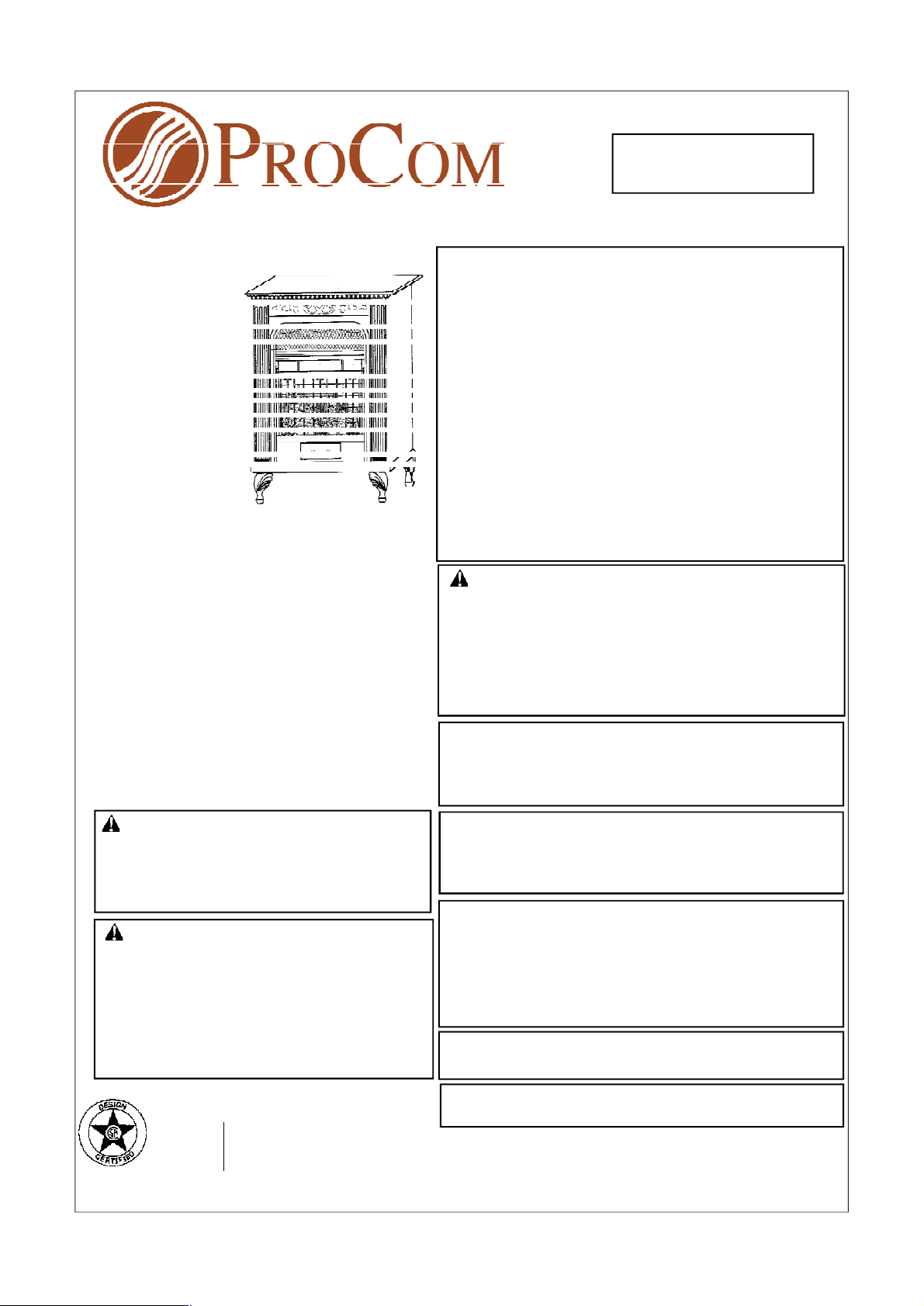
Figure1-Compact Vent-Free Fireplace
The following steps will help insure that water vapor does
not become a problem.
1. Be sure the heater is sized properly for the application,
including ample combusion air and circulation air.
2. If high humidity is experienced, a dehumidifier may be
used to help lower the water vapor content of the air.
3. Do not use an unvented room heater as the primary
heat source.
3
2
Page 4
AIR FOR COMBUSTION AND VENTILATION
WARNING: This heater shall
not be installed in a confined space
or unusually t ight constr uction
unless provisions are provided for
adequate combustion and ventilation air. Read the following instructions to insure proper fresh
air f or this and other fuel-burning
appliances in your home.
PROVIDING ADEQUATE
VENTILATION
The foll owing are excerpts from
National Fu el Gas Code, NFPA 54/
ANSI Z223 .1.Sect ion 5.3, Air f or
Combustion and Ventilation.
All spaces in homes fall into one
of t h e th ree f ol lowing v entilati on
classifications:
1. Unusually Tight Construction
2. Unconfined Space
3. Confined Space
The information on pages 4 through
5 will help you classify your space
and provide adequate ventilation.
Confined and Unconfined Space
The National Fuel Gas Code, ANSI
Z223.1 defines a confined sp ace as
a space whose v olum e is l ess
than 50 cubic feet per 1,000 Btu per
3
hour (4.8 m
per kw) of the aggregate input rating of all appliances
installed i n that space and an
unconf ini ng space as a space
whose volume is not less than 50
cubic feet per 1,000 Btu p er hour
3
(4.8 m
per kw) of th e aggr egat e
input r ating of all appliances installed in that space. Rooms communicating directly with the space
in which the appliances are
installed*, through openings not
furn ished with doors, are considered a p art of the un confi ned
space.
This heater shall not be installed
in a conf ined space or unusually
tight cons truction un less provisions
are pr ovided for ad equate combustion an d ventilation air.
* Adjoining rooms are communicating only if there are doorless
passageways or ventilat ion grills
betwee n them.
Unusually Tight Construction
The air that leaks around doors
and w indows may provide enou gh
fresh air for com bustion and
ventilation. However, in buildings of
unusually tight constr uction, you
must provide additional fresh air.
Unusua lly tight constr uction is
defined as cons tr uc tion wher e:
a) walls and ceilings exp osed to
the outside atmosphere have a
continuous water vapor retarder with
-11
a rating of one perm ( 6×10
2
pa-sec-m
gasketed or s ealed a
) or le ss with openi ngs
nd
kg per
b) weather stripping has been
added on windows that open and
doors a
nd
c) caul ki ng or seal ant s are applied to areas such as joints around
window and door frames, between
sole plates and floors, between wallceiling join t s, be tween wall panels,
at penetrations for plumbing,
electrical, and gas lines, and at other
openings.
If your home meets all of the
three criteria above, you must provide additional fresh air. See Venti-
latio n Air From Outdoors, pa ge 5.
If your home does not meet all of the
three criteria above, proceed to
Determining Fresh-Air Flow For
Heater Location , below.
AIR FOR COMBUSTION AND VENTILATION
DETERMINING FRESHAIR FLO W FOR HEATER LOCATION
Determining if You Have a Confi ned or Unconfined Space
Use th i s worksh eet to d etermi n e if you have a c onfi n ed or un confin ed sp ace.
Space: Includes the r oo m in which you will install heater plus any adjoining rooms with doorless passageways
or ventilation grills between the rooms.
1. Deter mi ne the volu me of th e sp ac e (len g t h
Length
Example: Space size 20ft. (length)
If additional ventilation to adjoining roo m is supplied with grills or openings, add th e volume of these
rooms to th e tota l volume of th e sp ace.
2. Divide the space volume by 50 cubic feet to determine the maximum Btu/Hr the space can support.
(volume of space)÷50 cu. ft.=(Maximum Btu/Hr the space can support)
Example: 2560 c u. ft. (volume of space)
Width×Height= cu.ft. (volume of space)
×
16ft. ( width)×8ft. (ceiling height)=2560 cu. ft. (volume of space)
×
width×height).
×
÷50 cu.ft.=51.2 or 51,2 00 (maximum Btu/Hr the space can support)
4
3
Page 5
3. Add the Btu/Hr of all fuel burning appliances in the space.
Vent-free heater
Gas water hea te r*
Gas furnace
Vented gas heater
Gas heater logs
Other gas applia nces* +
Total =
*Do not include direct-vent gas appliances. Direct-vent draws combustion air from the outdoors and
vent s to the outdoors.
4. Compare the maximum Btu/Hr the sp ace c an support w i th the act ual am o unt of Btu/ H r use d.
Btu/Hr (maximum the space can support)
Btu/Hr (a ctual amount of Bt u/Hr used)
Example : 51,200 Btu/Hr(maximum the space can support)
56,000 Btu/Hr(actual amount of Btu/Hr use d)
The sp ace in t he ab ove example is a con fined spac e bec ause th e ac tual B tu/H r used is m ore than th e
maximum B tu/H r the sp ace can support.
You must provide additional fresh air. Your options are as follows:
A. R ewo rk w o rksh eet, add ing th e sp ac e of an ad jo ining ro om . If the extra sp ac e pro vides an un co n fined
space, remove door to adjoining room or add ventilation grills between rooms. See Ventilation Air From
Inside Building (below).
B. Vent room directly to the outdoors. See Ventilation Air From Outdoors (bel ow) .
C. Install a lower Btu/Hr heater, if lower Btu/Hr size makes room uncon fined.
If the actual Btu/Hr used is less than the maximum Btu/Hr the space can support, the space is an
uncon fined space. You will need no additional fresh air ventilation.
WARNING: If the area in which the heater may be operated is smaller than that defined as an unconfined space
or if the building is of unusually tight co nstruction, p rovide adequate combu stion and ventilation air by one of the
methods described in the National Fuel Gas Code, ANSI Z223.1/NFPA 54, Air for Combustion and Ventilation, or
app lic ab le lo cal co d es.
Btu/Hr
Btu/Hr
Btu/Hr
Btu/Hr
Btu/Hr
Btu/Hr
Btu/Hr
Example:
Gas wat er heater 30,000 Btu/Hr
Vent-free heater +
Total = 56,000 Btu/Hr
26,000 Btu/Hr
Ventilation Air From lnside Building
This fresh air wo uld c ome from an a djoin ing un confined space. When ventilating to an adjoining
unconfined space, you must prov ide two permanent openings: one within 12" of the ceiling and
one within 12" of the floor on the w all connecting
the two spaces (see options 1 and 2, Fig ure 2).
You can also remove door into adjoinin g r oom
(see option 3, Figure 2). Follow the National Fuel
Gas Code . NFPA 54/ANSI Z223.1. Section 5.3,
Air for Combustion and Ventilation for required
size of ventilation grills or ducts .
Ve n t ila tion Air From Outdo or s
Provide extra fre sh air by using ventilatio n grills or
Figure 2 -Venti lation Air from Inside Building
ducts. You must provide two permanent openings:
one within 12" of the ceiling and one within 12" of the
floor. Connect these items directly to the outdoors or
spaces o pen to the outdoors. These spaces include
attics and crawl spaces. Follow the National Fuel
Gas Code, NFPA 54/ANSI Z223.1, Section 5. 3. Air
for Combustion and Ventilation for required size of
ventilation grills or ducts .
IMPORTANT:Do not provide openings for inlet
or outlet ai r into attic if attic has a t hermostatcontrolled power vent. Heated air entering th e
attic will activate the power vent.
Figure 3 -Ventilation Air f rom Outdoors
W ARNING: Re wor k worksheet, addi ng the s pa c e of the ad joini ng unc onfined space. The
combined spaces must have enough fresh air to supply all appliances in both spaces.
5
4
Page 6
NOTICE: This heater is in-
tended for u se as supplemental
heat. Use this heater along with
your prim ary h eating system . D o
not install this heater as your
primary heat source. If you have a
central heating system, you may
run system's circulating blower
while using heater. This will help circulate the heat throughout the
house . In the event of a po wer
outage, you can use this heater as
your primary heat source.
WARNING: A qualified s ervice
per so n mu st insta ll h ea ter. Fo llo w
all local co des.
WARNING: Never in st all th e
heater:
in a bedroom or bathroom
in a recreational vehicle
where curtains, furnit ure, clothing,
or other flammable objects are
less than 36 inches from the
front, top, or sides o f th e h eater
in high traffic areas
in windy or drafty areas
INSTALLAT ION
Figure 4 -Minimum Clearance to Wall
CAUTION: This heater creates
warm air currents. Th ese currents
move heat to wall surfaces next to
heater. Installing heater next to vinyl
or cloth wall coverings or operating
heater where impu rities (su ch as
tobacco smoke, aromatic candles,
cleaning fluids, oil or kerosene
lamp s, e tc . ) in th e air exist ,m ay d iscolor walls.
WARNING: Maintain the minimum clearances. If you can, provide greater clearances from floor,
ceiling, and adjoining side and
back walls.
IMPORTANT: Vent-free heaters add
moisture to the air. Alth oug h this is
beneficial, installing heater in rooms
without enough ventilation air may
cau se m ild ew . S ee Air for Combustion
and Ventilatio n, pages 4 through 5.
CHECK GAS TYPE
Use only the type of gas indicated on
the plate. If your gas supply can not
meet that requirement, do not install
heater. Call dealer where you bought
heater from for proper heater type.
CLEARANCES TO COMBUSTIBLES
(V ent -Fr e e Op erat i on On ly )
Carefully follow the instructions below.
This fireplace is a freestanding u nit
designed to set directly on the floor.
6
5
IMPORTANT: You must main tain
minim um wall and ceiling clear an ces
during installation. T he minimum
clearances are sho wn in F igure 4 .
Measure from out ermost point of f ireplace top.
Minimum Wall and Ceiling
Clearances
(see Figure 4)
A. Clearances from outermost point
of fireplace top to any combustible side
wall should not be less than 12 inches.
B. Clearances fro m th e fireplac e to p
to the ceiling should not be less than
48 inches.
Page 7
CONNECTING TO GAS SUPPL Y
WARNING: A qualified service person mus t con ne ct he at e r to ga s s upply.
Fo l l ow al l l o c a l c od e s .
CAUTION: Never connect heater
directly to the gas supply. This heater
requires an external regulator (not
supplied). lnstall the external regulator
between the heater and gas supply.
INSTALLATION ITEMS NEEDED
Before installing heater, mak e sure you
have the items listed below.
piping (check local codes)
sealant (resistant to natural or propane/
LP gas)
equipment shutoff valve*
test gauge connection*
sediment trap
see joint
pipe wrench
flexible gas hose ( c heck loc al c odes).
* A CSA design-cert ified e quipment shutoff
valve with 1/8
altern ative to test gaug e conn ect ion.
Purchase the optional CSA designcertifie d equipment shutoff va lve from
your d eal er. See Accessories, page 14.
WARNING: Never connect heater to
private (non-utility) gas wells. This gas
is commonly known as wellhead gas.
Front
of
stove
unit
" NPT tap is an acceptable
Front View
Side View
INSTALLATION
Continued
The installer must supply an external
regulator. The external regu lator will
reduce incoming gas pressure. You
must reduce incoming gas pressure
to between 11 to 1 4
not reduce incoming gas pressure,
heater regulator damage could occur .
lnstall external r egulator with the vent
pointi ng down as shown in Figure 6.
Pointing the vent down protects it
from freezing rain or sleet.
CAUTIO N: Onl y use a ne w black
iron or steel pipe. Internally-tinned
copper tubing may be used in certain areas. Check your local codes.
Use pipe of 1/2
to allow proper gas volume to heater.
If pipe is too small, undue loss of
pressure will occu r.
Installation must include an equipment shutoff valve, union, and plugged
" NPT tap. Loca te N P T tap within
1/8
rea ch f or test gauge hook up. NPT tap
must be u pstr eam from heat er (see
Figure 7).
Figure 6- External Regulator
With Vent Pointing Down
inches. If you do
" diameter or greater
IMPORTANT: Install equipment
shutoff valve in an accessible
location. The equ ipment shutoff
valve is for turning on or shutting
off the gas to the appliance.
Apply pipe joint sealant lightly to
male threads.This will prevent excess sealant from going into pipe.
Excess sealant in pipe co uld result in clogged heater valves.
CAUTION: Use pipe joint sealant that is resistant to liquid
petroleum(LP) gas.
W e recommend that you install a
sediment trap in supply line as
shown in Figure 7. Locate sediment
trap w her e it is within reac h fo r
cleanin g. Install in piping system
between fuel supply and heater.
Locate sediment trap where
trapped matter is not likely to freeze.
A sediment trap traps moisture
and contaminants. This keeps them
from going into heater controls. If
sediment trap is not installed or
is installed incorrectly, heater may
not run properly.
CAUTION: Avoid damage to
reg ulato r. H o ld gas reg u la t o r wit h
wrench when connecting into gas
piping and/or fittings.
NG MODEL S: 5” to 10.5” W.C.
Gas supplier provides external
regulator for natural gas.
Figure 5- Gas Regulat or Locat i on and
Gas Line Access Into Stove Cabinet
Figure 7 -Gas Connection
* Purc h ase the opt ional C SA d esi gn- c erti f ied equipm ent sh u tof f valve from your dealer. See Accessories, p age 14 .
** 11” W.C. p r es sure is th e minim um inlet pr es s ur e for pur pos e of input adjus t m ent.
7
6
Page 8

CHECKING GAS CONNECTIONS
INSTALLATION
Continued
WARNING: Test all gas piping
and connections for leaks after installing or servicing. Correct all leaks at
once.
Pressure Testing Gas Supply
Piping System
T est Pressures In Excess Of 1/2
PSIG(3.5kPa)
1. Disconnect heater with its
appliance main gas valve (control
valve) and equipment shutoff valve
from gas supply piping system.
Pressures in excess of 1/2 psig
will damage heater regulator.
2. Cap off open end of gas pipe
where equipment shutoff valve
was connected.
3. Pressurize supply piping system
by either usin g compressed air or
opening propane/ LP supply valve.
4. Check all joints of gas supply
piping system. Apply mixture of
liquid soap and water to gas
joints. Bubbles forming show a
leak.
5. Co rrect all leaks immediately.
6. Reconnect heater and equipment
shutoff valve to gas supply. Check
reconnected fittings for leaks.
WARNING: Never use an open
flame to check fo r a leak. Apply a
mixture of liquid soap and water to
all join ts. Bub bles form ing show a
leak. C orr ec t all lea k s im med ia tely.
Pressure Testing Heater Gas
Connections
1. Open equipment shutoff valve
(see Figure 8).
2. Open gas supply valve.
3. Make sure control knob of heater
is in the OFF position.
4. Check all joints from equipment
shutoff valve to control valve
(see Figure 9).
Apply mixture of liquid soap and
water to gas joints. Bubbles forming show a leak.
5. Correct all leaks immediately.
6. Light heater (see Operating Heater,
p age 9 ). Ch eck all other internal
joints for leaks.
7. Turn off heater (see To Turn Off
Gas to Appliance, page 9 ).
CAUTION: Make sure external
regulator has been installed betwee n natural gas suppl y and heater.
See guidelines under Connecting to
Gas Supply, page 7.
Test Pr es sur es Equal To or Le ss
Than 1/2 PSIG ( 3.5 kPa )
1. Close equipment shutoff valve
(see Figure 8).
2. Pressurize supply piping system
by either using com pressed air or
opening gas supply tank valve.
3. Check all j oints from gas meter to
equipment shutoff valve (see Fig ure 9). Apply mixture of liquid
soap and water to g as joints.
Bubbles forming show a leak.
4. Co rrect all leaks immediately.
Figure 8 -Equi pment Shutoff Valve
Figure 9 -C hecking Gas Joi nt s
7
8
Page 9

INSTALLATION
Continued
INSTALLING LOGS
WARNING: Failure to position
the pa rts in accor d ance with th e se
diagrams may result in property
damage or personal injury.
CAUTION: After i nsta llation and
periodically thereafter, check to ensure that no flame comes in
contact with any log. With the heater
set to HIGH, check to see if flames
contact any log. If so, reposition logs
according to the log installation
instr u ct io n s in th is m an u al. F lam es
contacting logs will create soot.
IMPORTANT: Make s ure log does not
cover any burner ports (see Figure10).
Figure 10 -Installing Log Set
(Top View)
OPERATING HEATER
FOR YOUR SAFETY
READ BEFORE
LIGHTING
WARNING: If you do not
follow these instru ctions exactly, a
fire or expl osion may result causing
property damage, personal injury or
loss of life.
A. This appliance has a pilot which
must be lit by hand. When
lighting the pilot, follow these
instructions exactly.
B. BEFORE LIGHTING smell all
around the appliance area for
gas. Be su re to smell next to the
floor because some gases are
hea vier t h an air an d will se tt le
on the floo r.
WHAT TO DO IF YOU SMELL GAS
See WARNING on Page 2 for proper
instructions.
C. Use only your hand to push in or
turn the gas control knob. Never use
too ls. If th e kn ob will no t p u sh in or
turn by hand, don't
tr y to rep a ir it . C all a q ua lified s erv ice
technician or gas supplier. Force o r attempted rep air may result in a fire or
explosion.
D. Do not use this appliance if any
part has been under water. Immediately call a qualified service technician
to inspect the appliance and to replace
any part of the control system and any
gas control which has been under water.
LIGHTING INSTRUCTIONS
1. STOP! Read the safety
information on page 2.
2. Make sure equipment shutoff
valve is fully open.
3. Turn control knob clockwise
to th e O FF position .
4. W ait five (5) minutes to clear out
any gas. Then smell for gas,
including near the floor. If you
sme ll gas, STOP ! Fo llow "B " in
the safety information on page 2. If
you don't smell gas, go to the
next step.
5. Tu rn control knob counterclockwise
to the PILOT position. Pre s s in
control knob for five seconds (see
Figure 11).
Note: Yo u may be running this
heater for the first time after
hooking it up to gas supply. If so,
the control knob may need to
be pressed in for 30 seconds
or less . This will allow air to
bleed from th e gas system.
6. With control knob pressed in,
press and release ignitor but ton.
This w ill light pilot. Th e pilot is
attac h ed to th e fro nt bu rn er. If
needed, keep pressing ignitor
button until pilot lights.
Figure 1 1 -Control Knob and
Ignit or But ton locati on
8
9
Note: If pilot does not stay lit,
contact a qualified service
person or gas supplier for
repairs. Until repairs are made,
light pilot with a match. To light
pilot with a match, see Manual
Lighting Procedu res, page 10.
7. Keep control knob pressed in for
30 seconds after lighting pilot.
After 30 seconds, release
control knob.
If control knob does not pop
out when released, contact a
qualified service person or gas
supplier for repairs.
Note: If pilo t goes out, repeat
steps 3 through 7. This heater
has a safety interlock system.
Wait one (1) minute for system
to reset before lighting pilot again .
8. Turn control knob counterclockwise
level. Th e burners should light.
Set control knob to any heat level
between HI and LO.
NOTICE: During initial operation of new hea ter, burning logs will
give off a paper-burning smell. An
orange flame will also be present.
Open a window to vent the smell.
This will only last a few hours.
CAUTION: Do not try to adjust
heating levels by using the
equipment shutoff valve.
to desired heating
TO TURN OFF GAS TO
APPLIANCE
Shutti ng Off Heat er
Turn control knob clockwise
the OFF po sitio n .
Shutting Off Burners Only (Pilot
stays lit )
Turn control knob clockwise
the PILO T/IGN pos ition .
Figure 12 -Pi lot
to
to
Page 10

OPERATING HEATER
Continued
THERMOSTA T CONTROL
OPERA TION
The thermostat control knob can be
set to any comfort level between HI
and LO. Th e thermostat will gradually
modulate the heat output and flame
height from higher to lower settings,
or pilot , in order to ma intain the
co mf o rt leve l you sel ect . Th e idea l
comfort setting will vary by household
depe nding upon the amount of space
to be heated, the output of the
cen tr a l heat in g syst em , etc .
Note: Selecting the HI setting with the
control knob will cause the burners
to remain fully on, without
modulating down in most cases.
MANUAL LIGHTING
PROCEDURE
1. Follow steps 1 through 5 under
Lighting Instructions, page 9.
2. Press control knob and light
pilot with match.
3. Keep control knob pressed in
for 30 seconds after lighting
pilot. After 30 seconds, release
control knob.
INSPECTING BURNERS
Check pilot flame pattern and
burner flame patterns often.
PILOT FLA M E P ATTERN
Figure 13 shows a correct pilot flame
pattern. Fi gure 14 shows an incorrect pilot flam e pat tern . Th e inc orr ect pilot
flame is not touching t he the rmocouple.
Th is will cau se the th ermo co up le to
cool. W hen th e thermocou ple cools,
the heater will shut down.
If pilot flame pattern is inco rrect, as
shown in Figure 14:
turn heater off (see To Turn
Off Gas to Appliance, page 9)
see Troubleshooting (pages 11
through 12).
BURNER FLAME P ATTERN
Figure 15 shows a correct burner flame
pattern. Figure 16 shows an incorrect
burner flame pattern. I f burner flam e pattern is incorrect:
turn h eater off (see To Tur n
Off Gas to Appliance, page 9)
see Troubleshooting, pages 11
through 12
10
9
CLEANING AND MAINTENANCE
WARNING: Turn off heater and
let cool befo re cleaning.
CAUTION: You must keep
control areas, burner, and
circulating air passageways of
heater clean. Inspect these
areas of heater before each
use. Have heater inspected
yearly by a qualified service p erson .
Heater may need more
frequent cleaning due to
excessive lint from carpeting,
bedding material, pet hair, etc.
CLEANING ODS/I GNIT OR AND
BURNER
Clean with a vacuum c leaner.
CLEANING MAIN AIR INLET HOLE
W e recommend th at you clean the unit
every three months or after 2500 hours
of operation. We also recommend that
you keep th e bur ner t ub e and pilot assembly clean and free of d u st and
dirt. To clean th ese parts we recommend using compressed air no greater
than 30 PS I. Yo u can use a vacuum
cleaner in the blow position. If
using compressed air in a can,
please follow the directions on the
can. If you don't follow directions
on the can, you could damage the
pilot assem bly.
1. Shut off the unit, including the
pilot. Allow the unit to cool for
at least thirty minutes.
2. Inspect burner, pilot and
primary air inlet holes on
injector holder for dust and dirt
(see figure 17).
3. Blow air through the
ports/slots and holes in the
burner.
4. Check the injector holder
located at the end of the
burner tube again. Remove
any large particles of dust, dirt,
lint, or p et h air w ith a soft clo th
or vacuum cleaner nozzle.
5. Blow air into the primary air
holes on the injector ho lder.
6. In case any large clumps of
dust have been pushed
into the burn er, repeat step s 3
and 4.
Page 11

CLEANING AND MAINTENANCE
Continued
Clean the pilot assembly also. A
yellow tip on the pilot flame
indicates dust and dirt in the pilot
assemb ly. There is a small pilo t air
inlet hole about two inches from
where the pilot flame com es out of
the p ilot assemb ly (see F igure 1 8).
With the unit off, lightly blow air
through the air inlet hole. You m ay
blow through a drinking straw if
compressed air is not available.
CABINET
Air Pass agew ays
Use a vacuum clea ner or pressur-
ized
air to clean.
EXTERIOR
Use a soft cloth damp ened with a
mild soap and water mixture. Wipe
the cabinet to remove dust.
LOGS
If you remove logs for cleaning,
refer to Installing Logs, page
19, to properly replace logs.
Replace log(s) if broken or chipped
(dime-sized or larger).
MAIN BURNER
Periodically inspect all burner flame
holes with the healer running. All
slotted burner flame holes should
be open with yellow flame present.
All round burne r f l a me hol e s should
be open with a small blue flame
present. Some bur ner flame holes
may become blocked by debris or
rust, with no flame present. If so,
turn off heater and let cool. Either
remove blockage or replace burner.
Blocked burner flame holes will
create soot.
Figure 18-Pilot Air Inlet Hole
Note: All troubleshooting items
are listed in or der of operat ion.
OBSERVED PROBLEM POSSIBLE CAUSE
1. Gas supply turned off or equipment
When ignitor button is
pressed, there is a spark at
ODS/pilot but no ignition.
shutoff valve closed.
2. Control knob not in PILOT position.
3. C on trol k no b n ot p resse d in while in
PILOT position.
4. Air in gas lines when installed.
5. Depleted gas supply.
6. ODS/pilot is clogged.
TROUBLE SHOOTING
WARNING: T urn off heater and
let cool before servicing. Only a
qualified se rvice pe rso n s hou ld
service and repair heater.
CAUTION: Never use a wire,
needle , or similar object to clean
ODS/pilot. This can damage ODS/
pilot uni t.
REMEDY
1. Turn on gas supply or open
equipment shutoff valve.
2. Turn control knob to PILOT position.
3. Press in contr ol knob while in PILOT
position.
4. Continue holding down control
knob. Repeat igniting operation
un t il a ir is re mo ve d .
5. Contact local p ropane/LP gas
company.
6. Clean ODS/pilot (see Cleaning
and Maintenance,page 10 ) or replace
OD S/ pilo t a ss emb ly.
7. G as re gu la tor se t ting is inc or r e ct.
11
10
7. Replace gas control.
Page 12

TROUBLE SHOOTING
Continued
OBSERVED PROBLEM POSSIBLE CAUSE
ODS/pilot lights but flame
goes out when control
kn ob is released .
Burner does not light after
ODS/pilot is lit.
Delayed ignition burner.
1. Control knob not fully pressed in.
2. Control knob not pressed in long
enough.
3. Equi p me nt s hut of f valv e not f ul ly open.
4. Thermocouple connection loose
at control valve.
5. Pilot fla me not touching thermocoupl e .
Th is allow s the rmoc oup le to c ool
causing the pilot flame to go out.
This problem could be caused by
one or both of the following:
A) Low gas pressure.
B) Dirt y or partially clogged ODS/
pi lot.
6. Thermocou ple damaged.
7. Control valve damaged.
1. Burner orifice is clogged.
2. Inlet gas pressure is t oo low.
3. Burner orifice diameter is too small.
4. Thermocoup le leads disconnected
or improperly connected.
1. Manifold pressure is too low.
2. Burner orifice is clogged.
REMEDY
1. Press in control knob all the way.
2. After ODS/pilot lights, keep
control knob pressed in for 30
seconds.
3. Open equipment shutoff valve all the
way.
4. Hand tighten until snug, then
tighten 1/4 t u rn mo r e.
5. A) Contact local propane/LP gas
com pany.
B) Clean ODS/pilot (see Cleaning
and Maintenance, page 10 ) or replace
CD S /p ilo t as se mb ly.
6. Replace thermocouple.
7. Contact Dealer or PRO-COM .
1.Clean burner (see Cleaning
and Maintenance, page 10) or replace
burner orifice.
2. Contact local propane/LP gas
company.
3. Replace burner orifice.
4 . Re conn ect lead s.
1. Contact local gas company .
2. Clean burner (see Cleaning and
Maintenance, page 10).
Burner backfiring during
combustion.
Slight smoke or odor
dur in g in itial operat io n.
Dark residue on logs
or inside of fireplace.
Heater produces a clicking/
ticking noise just after burner
is lit or shut off.
1. Damaged burner.
2. Gas regulator is defective.
1. Residues from manufacturing
processes.
2. Not enough air.
3. Gas regu lator is defective.
1. Improper log placement.
2. Air holes at burner inlet are blocked.
3. Burner flame holes are blocked.
1. Metal expanding while heating
or contracting while cooling.
11
12
1. Clean burner orifice (see Cleaning
and Maintenance, page 10).
2. Replace gas regulator.
1. Problem w ill stop after a few hours
of operation.
2. Check burner for dirt and debris.
If found, clean burner (see C leaning
and Maintenance, page 10).
3. Replace gas regulator.
1. Pro perly lo cate log s (see Installing
Logs, page 9).
2. Clean out air holes at burner inlet.
Periodically repeat as needed.
3. Remove blockage or replace burner.
1. This is common with most
heaters. If noise is excessive,
contact qualified service person.
Page 13

SPECIFICATIONS
EL250TYLA-B
EL250TYLA-W
EL250TYLB-O
EL250TYLA-C
EL250TYLB-DO
Btu 20,000/25,000 20,000/ 25,000
Gas Type LP Gas N atural Gas
Ignition Piezo Piezo
Manifold Pressure 8"W.C. 3"W .C.
Inlet Gas Pressu r e
(In. of water)*
Maxi mum 14" 10.5"
Mi nim u m 11" 5"
Dimensions, Inch es (H×W×D)
Stove 38 3/16”×26 3/8”×14 1/8”
Carton 37”×29 5/16”×15 5/16” (41 3/8” x29 5/16” x17 3/8” ** )
EN250TYLA-B
EN25 0TYLA -W
EN250TYLB-O
EN250TYLA-C
EN250TYLB-DO
Weight, lbs
St ove 73 (78***) 73 (78***)
Shipping 89 (94***) 89 (94***)
*For purpos es of input adjus tment
The carton dimension of model EL250TYLB & EN250TYLB
**
***The weight of model EL250TYLB & EN250TYLB
12
13
Page 14

REPLACEMENT PARTS
REPLACEMENT PARTS
Note: Use only original replacement
parts. This will protect your warranty
coverage for parts replaced und er
warranty.
PARTS UNDER WARRANTY
Contact authorized dealers of this
product. If they can't supply original
replacement part(s) call PRO-COM
at (877)886-5989 for referral
information.
When calling PRO-COM or your
de aler , h ave re ad y:
Your name
Your address
Model and se r i a l number s of
your heater
How heater was malfunction-
ing
Type of gas used (propane/LP
or
natural gas)
Purchase date
warranty card
Usually, we will ask you to
return the defective part to the
factory.
ACC ESSOR IES
Purchase these heater accessories
from your local dealer or call PRO-COM at
(877)886-598 9 for referral information. You
can also write to the address listed on the
front page of this manual.
FLEXIBLE GAS HOSE
Flexible gas hose is used fo r con necting the heater to gas suppy.
The flexible gas hose must be CSA
approved.
EQUIPMENT SHUTOFF V A LVE
Equipment shutoff valve with 1/8" NPT
tap. This part is not currently available
from PRO-COM.
P ARTS NOT UNDER WARRANTY
Contact authorized dealers of this
product. Call PRO-COM at (877)
886-5989 for referral information.
When call i ng PRO- COM, ha v e r e ady:
Model number of your heater
The replacement part nu mber
13
14
Page 15

ILLUSTRATED
PARTS BREAKDOWN
EL250TYLA-B
EL250TYLA-W
EL250TYLB-O
EL250TYLA-C
EL250TYLB-DO
EN250TYLA-B
EN25 0TYLA -W
EN250TYLB-O
EN250TYLA-C
EN250TYLB-DO
15
14
Page 16

PARTS LIST
EL250TYLA-B
EL250TYLA-W
EN250TYLA-B
EN25 0TYLA -W
This list contains replaceable parts used in your
heater. When ordering parts, follow the instructions
listed under Replacement Parts on page 14
of this manual.
EL250TYLB-O
EL250TYLA-C
EL250TYLB-DO
EN250TYLB-O
EN250TYLA-C
EN250TYLB-DO
15
11
16
Page 17

ILLUSTRATED
PARTS BREAKDOWN
EL250TYLA-B
EL250TYLA-W
EN250TYLA-B
EN25 0TYLA -W
16
17
Page 18

PARTS LIST
EL250TYLA-B
EL250TYLA-W
EN250TYLA-B
EN25 0TYLA -W
17
18
12
Page 19

ILLUSTRATED
PARTS BREAKDOWN
EL250TYLB-O
EN250TYLB-O
EN250TYLB - C
EL250TYLB-C
EN250TYLB-DO
EL250TYLB-DO
18
19
Page 20

PARTS LIST
EL250TYLB-O
EN250TYLB-O
EN250TYLB-C
EL250TYLB-C
EN250TYLB-DO
EL250TYLB-DO
20
19
Page 21

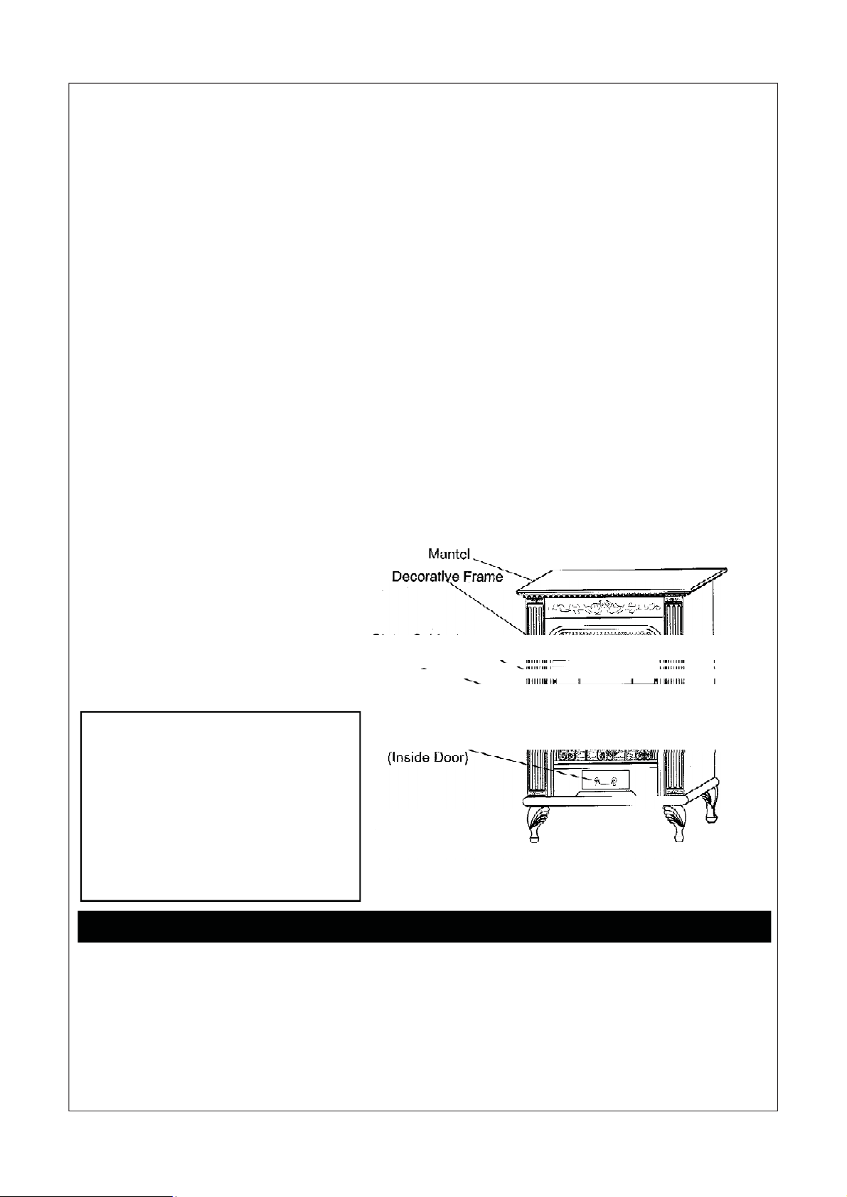
1. Install legs and pedestal decorating trim.
Lay the heater down on its back and install the
legs with care on the bottom panel (as shown in
Figure 1). Ma ke sure th e vein side is forw ards.
Except m od el EL(N )2 50TY LB
Install the pedest al decorati ng tri m (front and
side) under the pedestal with screws.
Figure 1
2. I nstall the decora tin g logs.
Figure 2
Fasten decorating logs 123 onto the correspondent angle iron (Figure 4).
Figure 3
Figure 4
Insert the pinhole on the upper part of log 4 into the pin on the left side of log 1. Place the
lowe r par t o n the flat ro of at th e lef t s ide of log 3 (Fig ur e 5).
Insert the pinhole on the upper side of log 5 into the pin on the right side of log 1. Place the
lower part on the flat roof at the right side of log 3 (Figure 6).
Figure 5
Figure 6
5. Ins tall th e h eate r ac cordi n g to th e Installat ion in th e owner’s manual.
20
21
Page 22

INSTALLING BLOWER ACCESSORY
BLOWER ACCESSORY MODEL NFHTX186
ACCESSORY NFHTX186
T ools required: Philips screwdriver
NOTI CE : Shut off gas heater during the following blower
installation.
1.From back of heater remove the knock
out c e n te r p anel with tw o brack e ts at th e
four sides with a Philips head screwdriver
(see Figure 1).
2. Attach the two brackets to blower hous
ing using four white screws provided in
blower kit (2 for each bracket) (see Fig
ure 2). Tighten screws securely. Then
guide the green groun ding means wire
and downlead of motor through the panel
capped hole.
3. Guide the four strand wire of downlead
through the panel hole. Connect the two
yellow leads an d the temperature con trol
switch on the temp er atu r e c ontr o lled
bracket togther. Secure the temperature
controlled bracket on the reflective panel
of firebox using two self-tapping screws
(See Figure 3-A).
4. Using the previously removed screws,
mount blow er assembly to sto ve by reat
ta ching the knock-out center panel to rear
panel. Draw the four strand c able back-
P
ward so as t o expo se t h e t hr ee bl ac k,
green, white lines on the four strand
cable at the bac k of rear panel.Be sur e
not to drop the temperature controlled
wire off the reflective panel. Connect the
green grounding means wire and four
strand cable together.Connect the two
black motor down leads respectively
and the remaining two black and white
wir e s t oge t he r by the s a me mea ns (s e e
Figure 3-A). (Note: the th ree wires
must be connected at the rear panel)
5. Using the thread that previously bond
the electrical wire to c ollect an d p ack
the outside connection wire of the
cable.
6. A . E N(L)250TYLA mo de l Guid e t he
operating control housing through the
bottom ho le of rear panel, and place
it on the mounting bracket in the door.
Mounting operating control housing to
the mounting bracket with two screw.
(see figure 4)
B. EN(L)25 0T YLBmo del Insert opera tion control housing at the back bot tom of stove.Use two black screws
provided in blower kit. Mount blower
operation control housing to the
bracket at the bottom of stove (see Fig
ure 5).
7. Chec k to mak e sure t hat th e po we r
co rd is co mplet ely clear o f blow er
wheel and ther e are no forei gn objects
in blower wheel.
8. Use screws provided in blower
k it to as semble the plate which
ass em b led w ith st rain re lief
bushing and po wer cord on the
knock-out center panel.
9.Peel off the backing paper and
stick the supplied wiring diagram
decal on th e b ack panel as show
in F igure 4-B.
10.Plug power cord into a con ve
nient 3-prong grounded wall
recep tacle near the stove.
WARNING: 1. ELEC TRICAL
GROUNDING INSTRUCTIONS:
This appliance is equipped
with a three-prong (grounding)
plug for your protection
against shock hazard and
shou ld be p lugg ed dir ectl y in to
a properly grounded threeprong receptacle.
2. Do not let the wires touch
the reflective panel of the
firebox.
motor and gr een wir e thr ough
the hole of the knock-out
panel.
11. Using Auto/O/man switch. Turn
12. All remaining parts from
Feed the wires of the
blower on and check for
operat ion. Tur n on Auto/O/Ma n
switch to the desired position.
Man position will remain constantly on. Auto position will be
control led by the thermostat on
fan blower unit. To stop the
operation, turn unit switch to the
O position.
blower kit may be discarded.
Figur e 1 Removing Kno ck- out Panel
22
21
Figure 2 Attaching Brackets To Blower
Page 23

INSTALLING BLOWER ACCESSORY
BLOWER ACCESSORY MODEL NFHTX186
Figure 3-A R outing Power Cord
MODEL EL(N)250TYLA
Figur e 4 Mount in g Contr ol hosi ng
Wiring Diagram
Decal
Figure 3-B R outing Power Cord
Figure 5 Mounting Control Housing
22
23
MODEL EL(N)250TYLB
 Loading...