

Page 1
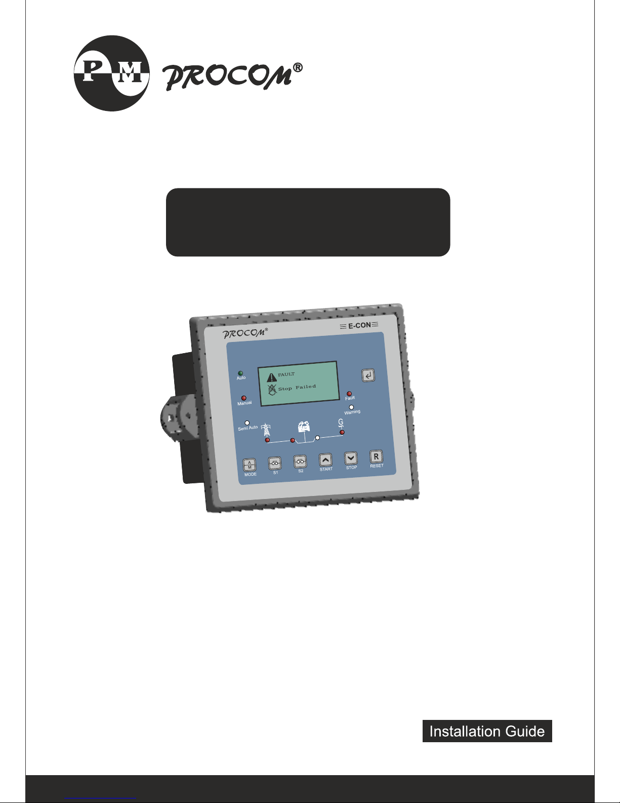
OPERATING INSTRUCTIONS
ECON-A-4C/A/S/M
Page 2

Page 3

INDEX
1.0 Introduction
2.0 Salient features, Protection & Supervision
3.0 Display/ Front Panel
4.0 Switches Description
5.0 LED Annunciations Description
6.0 Lamp Test
7.0 Digital Input
8.0 Analog Input
9.0 Digital Output
10.0 Modes of Operation
10.1 AMF Mode (ECON-A & ECON -A-4C)
10.1.1 Auto Mode
10.1.2 Semi Auto Mode
10.1.3 Manual Mode
10.2 Auto Stop Mode ( ECON-A & ECON - A-4C or ECON-S)
10.3 Manual Controller ( All models)
11.0 Setting Procedure
12.0 Parameter Mode
12.1 System Parameter
12.2 Generator Parameter
12.3 AMF Parameter
12.4 Protection Parameter
12.5 RS 485 parameters
12.6 Reset Service Alarm
12.7 Adjust Clock
12.8 Reset Password
13.0 Model Selection Chart
14.0 Load Management
15.0 Event Recording
16.0 Faults
16.1 Internal Faults
16.2 External Faults
16.3 Fault Reset
17.0 Communication
18.0 MODBUS Specifications.
19.0 Terminal description
20.0 Specifications
21.0 Dimension
Operating Instructions
Page - 1
Page 4

• 1.0 Introduction
Microprocessor based controller for DG Set which can be configured as both
automatic or manual controller.
ECON comes in various models to cater for varieties of requirements:
• ECON-A-4C
• ECON-A
• ECON-S
• ECON-M
• ECON-A-4C: It is a AMF controller with 4 channel of analog measurement
and can be site configured as ECON-A or ECON-S or ECON-M.
• ECON-A: It is a AMF controller with 3 Analog channels and is site
configurable to ECON-S or ECON-M
• ECON-S: It is a manual controller with Shunt trip contact for MCCB. This is to
avoid shutting down the engine on load in manual operation. After the shunt
trip is initiated the generator stops after re-cooling time. ECON-M is sub set of
this model
• ECON-M: This is a pure manual controller for manual operation only.
All these models can be ordered with optional features such as RS485
communication,3 Extra digital inputs of Canopy fan current protection. This
manual has to be read along with the controller selected and all the features
may not be available in all the models.
• Display: 128*64 pixel graphial backlit LCD for ease of readout and symbolic
representation.
• Cyclic Timer based Engine Operation. Maximum engine on time as well as
rest time are programmable
• Fan Current monitoring for canopy fan (Optional)
• Menu driven MM1 for easy in field configuration without PC or any
customized equipment.
• Load Management . Load Dependent start/stop of 2nd DG in case of two DG
application.
• Periodic Automatic Start of engine if not used for a predefined time to charge
the battery as well as maintenance.
• ECON reminds user for timely service by indicating service due alarm.
• True RMS measurement of all measured parameters with 1% accuracy of
measured value.
• Plug in connectors for error free replacement.
• Programmable DG on delay, DG continuous on time, DG Rest Time, warm-up
time along with 33 other times.
• Automatic real time based DG Start and Stop(Manual Control Configuration.).
• Dimensions 167 х 129 х 41.8 mm.
Operating Instructions
Page - 2
Page 5

• 2.0 Salient Features, Protection and Supervision
• Mains Measurements
◦ 1 Phase/ 3 Phase Voltage
◦ 1 Phase/ 3 Phase Current
◦ Frequency
◦ PF, KW, KVA,
• Generator Measurements
◦ 1 Phase / 3 Phase Voltage
◦ 1 Phase / 3 Phase Current
◦ Frequency
◦ PF, KW, KVA, KWH .
◦ Battery Voltage
◦ Water Temperature
◦ Oil Pressure
◦ Fuel Level
◦ RPM
◦ Run Hour
◦ Service Due Hour
• Protection / Supervision Mains
◦ Under/Over Voltage
◦ Under/Over Frequency
◦ Phase Sequence
◦ Voltage Unbalance
◦ Overload
• Protection / Supervision DG
◦ Under/Over Voltage
◦ Under/Over Frequency
◦ Current Unbalance
◦ Over Speed
◦ RWL
◦ LLOP
◦ HWT
◦ LFL
◦ Charging Alternator/V-belt
◦ Emergency off
◦ Service Due
◦ Fail To Start
◦ Fail To Stop
• Digital Input : 10 digital [3 fixed, 4 programmable, 3 programmable (optional)]
• Output: 9 digital
Operating Instructions
Page - 3
Page 6
◦ AMF Operation: 9 outputs (five fixed and three programmable) and one for
charging Alternator
• Fault Data Recording: Last 64 fault with date and time stamping
• Event Recording: Last 64 event with date and time stamping
• Start Stop Recording: Last 100 records with date and time stamping
• Password Protection: Three digit password protection for system settings.
• Real Time Clock (RTC)
• Communication: RS232, USB, Fully Isolated RS485(Optional)
• Provision for switching ON or OFF the measurement for individual sensors.
• Option of warning or tripping when open sensor is detected
• Programmable crank cut off method based on either voltage built up, or oil
pressure build up & voltage built up
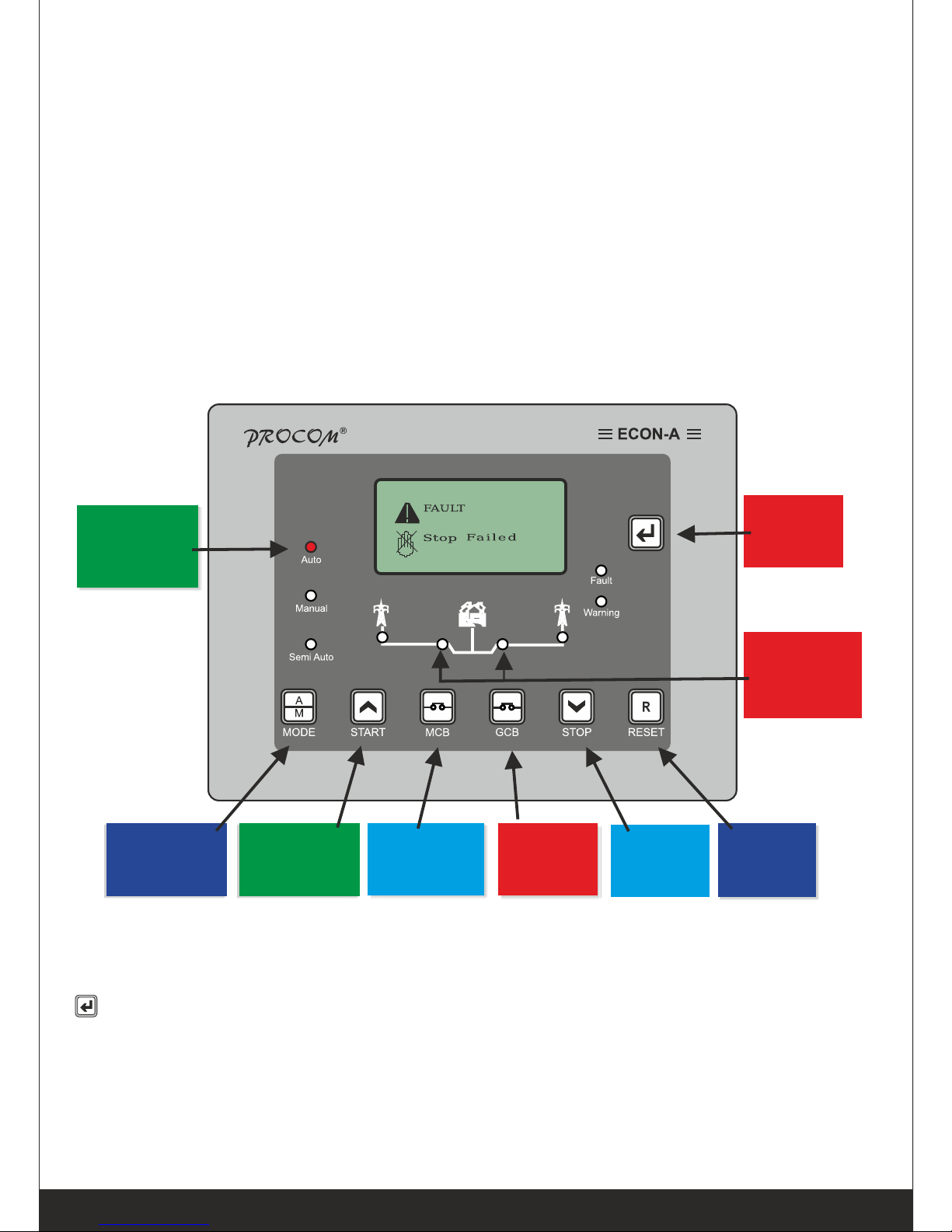
• 3.0 Display / Front Panel
• 128x64 pixels Graphical LCD Display for ease of readout. Parameters are
displayed in English along with symbolic representation. Normally the display
auto scrolls and displays a parameter for 10 seconds, but any time the Next key
( ) can be pressed to select the next parameter window.
• 4.0 Switches Description
ECON has 7 switches provided on its front panel. The table below describes
the operation of these.
Start
Switch
MCB
Switch
Reset
Switch
Mode
Indication
LEDs
Next
Switch
GCB
Switch
Stop
Switch
Mode
selection
switch
Mains & DG
Contactor
Indicator
Operating Instructions
Page - 4
Page 7
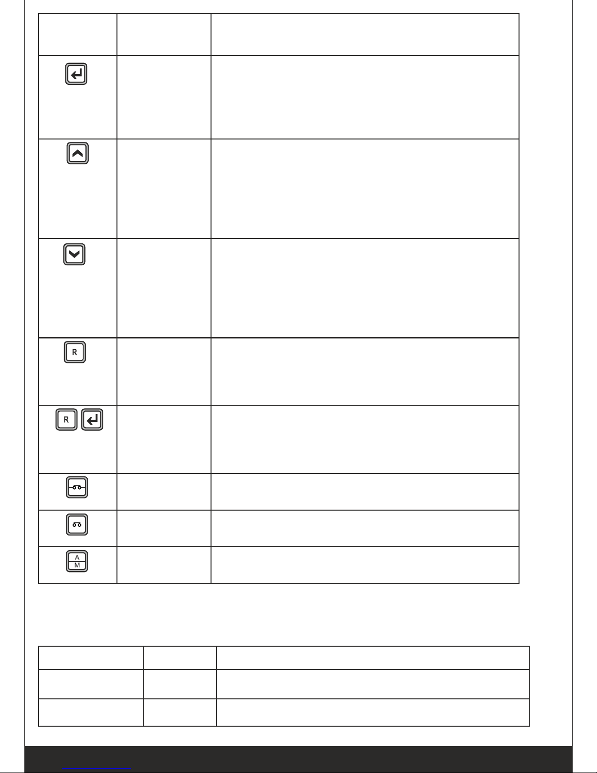
Switch
Symbol
Switch
Function
Description
Next
Normal operation mode: In this mode, it is
used to change the parameters being
displayed on LCD.
Programming Mode: Next key is used to
select the next parameter to be programmed.
Increment
/Start
This key has dual function
Programming Mode: It is used to increment
the value of the parameters under
programming.
Manual mode: it is used to issue the crank/
start command to DG
Decrement
/Stop
This key has dual function
Programming mode: It is used to decrement
the value of the parameter under
programming.
Manual mode: It is used to issue the stop
command to DG
Reset
Reset key resets the Hooter and Fault signals.
The first press shall reset the hooter and next
shall reset the faults. A long press of 1 Sec
shall reset both.
Programming
/History
Fault Mode
Entry
If both the keys are pressed simultaneously
the unit will enter in Programming Mode
History Fault/Service Hours
MCB
In Manual Mode this toggles the mains
contactor, On/Off
GCB
In Manual Mode this toggles the generator
contactor, On/Off
MODE
Toggle between Auto, Manual & Test Mode
• 5.0 LED Annunciations Description: ECON has nine annunciations on its
front panel. These either announce the faults or indicate status of the
system.
Nomenclature
Symbol
Description
Auto
Led lights up when ECON is in Auto mode
Manual Mode
Led lights up when ECON is in manual mode
Operating Instructions
Page - 5
Page 8
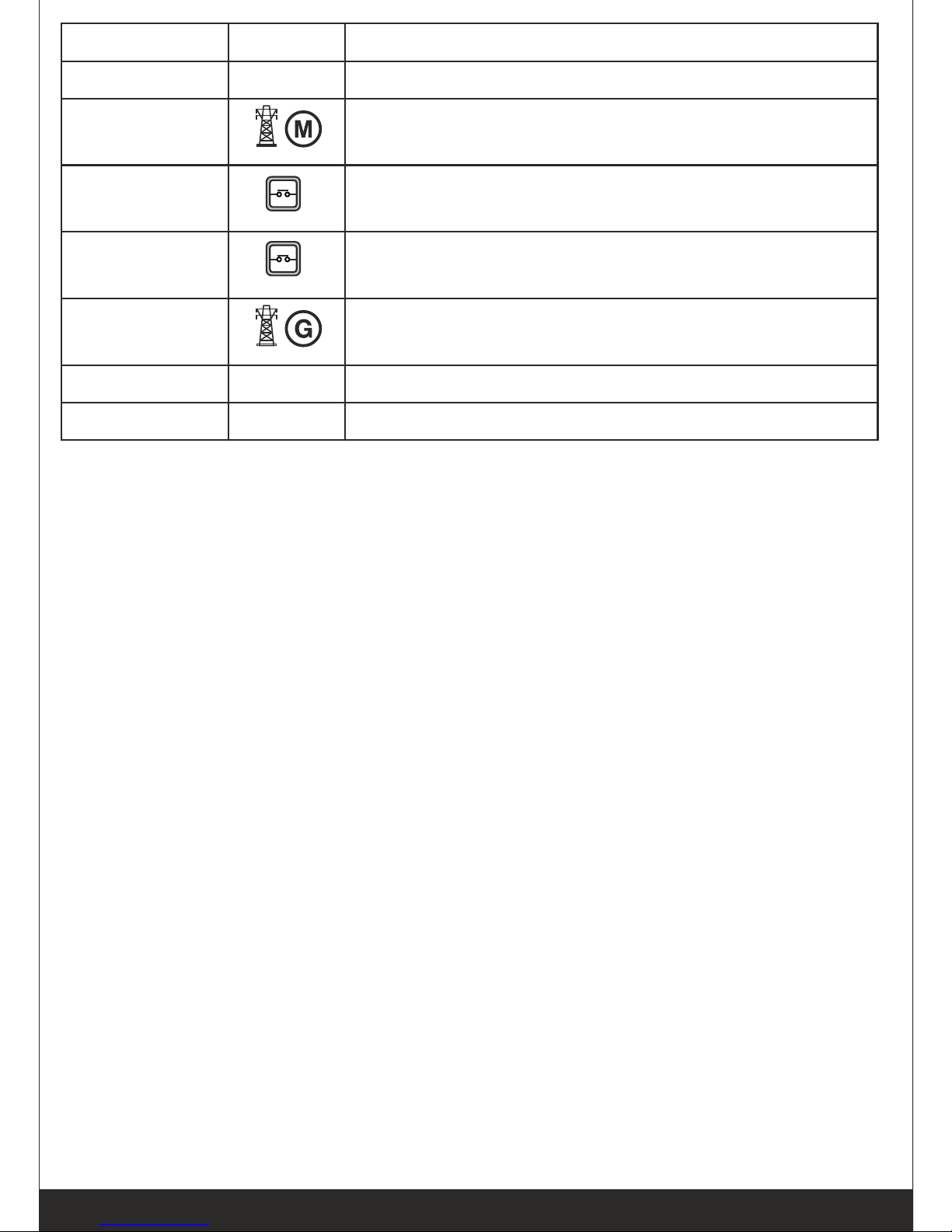
Nomenclature
Symbol
Description
Semi Auto
Led lights up when ECON is in Semi Auto
Mains Voltage
This symbol lights up continuously if Main is
healthy else starts blinking.
MCB
LED turns on in case the mains breaker is
switched on or else turned off
GCB
LED turns on in case the DG breaker is switched
on or else turned off
DG Voltage
This indication glows continuously when the
generator is running.
Warning
This LED blinks in case of a warning.
Fault
This LED blinks in case of a fault
• 6.0 Lamp Test:
If the ECON is switched on while the reset switch is pressed, all the LEDs
start blinking till reset switch is kept pressed.. This state shall persist till the
switch is kept pressed and on release of the switch ECON shall start
functioning normally
• 7.0 Digital Input:
ECON has 10 digital input as below
• Fixed Inputs
◦ Remote Start,
◦ Remote Stop / Semi Auto
◦ Emergency
• Programmable 4 inputs each can be programmed as one of the
following inputs.
◦ RWL Switch ◦ LLOP Switch
◦ Fuel Switch ◦ HWT Switch
◦ Oil Level Switch ◦ Canopy Temperature Switch
◦ Oil Temperature Switch
• Optional programmable 3 inputs each can be programmed as one of the
following inputs.
◦ Earth Fault ◦ Oil Level Switch
◦ Canopy Temperature Switch ◦ Oil Temperature Switch
Operating Instructions
Page - 6
Page 9

Operating Instructions
Page - 7
• 8.0 Analog Input: ECON has 4 Analog Input
◦ Low Lube Oil Pressure Sensor
◦ High Water Temperature Sensor
◦ Low Fuel Level Sensor
◦ OIL Temperature (ECON-A-4C only )
• 9.0 Digital Output: ECON has 9 digital outputs :
• Programmable output
Three digital outputs can independently be configured for the any functions
from the list below.
◦ Unit Healthy ◦ Load Warning
◦ Fuel Pump ◦ Heater/Choke
◦ Pull Solenoid ◦ None
• Fixed output: The remaining 6 digital outputs are fixed:
◦ Charging Alt( Battery Voltage) ◦ Crank
◦ Solenoid ◦ Hooter
◦ Mains Contactor ◦ Generator Contactor
• 10.0 Modes of Operation
10.1 AMF Mode (ECON-A & ECON -A-4C)
• 10.1.1 Auto Mode
ECON monitors the Mains supply, if Mains supply varies beyond set limit of
under/over voltage or under/over frequency or voltage unbalance for more
than their individual programmed supervision time, ECON releases the MCB
contactor (to protect the contactor from failure because of low input voltage)
and attempts to starts the generator after the following conditions are meet:
1. If engine start delay is enabled than the engine will wait for the programmed
delay before cranking the engine
2. In case the mains voltage returns to normal before cranking the engine the
engine shall not be cranked.
Heater/Fuel Pump contact are switched on depending upon their settings.
Heater/choke/glow plug is first switched followed by fuel pump. Next ECON
cranks the engine. Crank command is withdrawn once the engine start which
is detected, either by LLOP pressure or by build-up of generator voltage, as
per the setting by the user. Max duration of crank command is user settable.
In case of non-start of the engine ECON re-cranks it till it starts or user
programmed crank attempts are exhausted. If generator fails to start after the
maximum programmed crank attempts, Fail to Start LED starts blinking,
indicating start failure and the hooter is switched on.
After successful start of the generator, it is allowed to warm up for a user
programmed time before the load is transferred to generator.
While the generator is running ECON monitors it for external fault (Digital
Page 10

Inputs: Emergency, V-Belt, RWL,, LLOP Switch etc) and internal faults
(Measured Values faults: LLOP, HWT, Fuel, Over Load, voltage and
frequency).
On persistence of any fault for more than the programmed supervision
delay,for that fault, generator is stopped, corresponding fault is announced &
hooter is switched on. On restoration of healthy mains supply, continuously,
for the programme duration the load is transferred to the mains and generator
is stopped after expiry of re-cooling time. In case mains again become
unhealthy during the re-cooling period the load is switched to generator.
After successful stopping of the generator either normally or on fault the Fuel
Pump Contact is removed. In case of fail to stop, the Fuel Pump Contact is
not removed to avoid air locking.
Cyclic Operation: ECON can be programmed to automatically shut down
the engine, for a predefined duration, after a predefined duration of
operation, even if the mains is unhealthy. In case the mains continue to be
unhealthy this cyclic operation will continue till the mains is restored.
• 10.1.2 Semi Auto Mode
Semi Auto Mode is sub set of Auto mode. This mode can be selected by
pulling the pin 28(Semi/Auto) low and selecting auto mode from the front
panel. The Auto LED will blink indicating that the unit is in Semi-Auto Mode.
In this mode the unit does not automatically starts the engine after the mains
has failed and mains supervision timer has expired but waits for an external
start signal pin 29(Remote Start/Stop). Once the start signal is given the unit
now functions like auto mode with 3 crank attempts. The unit can be stopped
by pulling low Pin 29(Remote Stop). Both Remote start and remote stop are
one touch and hence should not be continuously activated. These pins shall
only function during semi auto mode.
• 10.1.3 Manual Mode
ECON-A, in this mode is under the manual control of the operator for starting
and stopping of the generator. Engine has to be started manually by manually
pressing “Start” switch. The “Start” switch shall not operate if GCB contact is
closed, to provide protection to generator. Once the generator is started the
load can be switched to generator by pressing “GCB” switch or to mains by
pressing MCB switch. At any given time, either of GCB or MCB can be
operational. Attempt to switch on GCB while MCB is on will be ignored and
vice versa. Both MCB and GCB key have dual function of either switching
ON or OFF the respective contactor. A press shall toggle the state.
Continuously pressing these keys shall keep toggling the status. To stop the
generator, switch off the GCB contactor and press “STOP” key. Any attempt
to stop the generator, while the GCB contact is engaged, shall be ignored.
While the generator is running ECON-A protects the generator by monitoring
all internal and external faults.
Operating Instructions
Page - 8
Page 11

• 10.2 MCCB Shunt trip or Auto Stop Mode (ECON-A , ECON -A-4C or
ECON-S)
This mode is a mix of Manual and Auto mode. In this mode the engine is
manually started but its shut down on the restoration of the mains. To make
sure that the engine is not shut down on load and also to recool the engine
before shutting it down it has provision to activate the shunt trip coil of MMCB
before shutting it down it has provision to activate the shunt trip coil of MMCB
and isolate the generator from load and engine is stopped after running it for
the predefined recooling time.
Engine can be started or stopped either the front keys or remotely by use of
Remote start/stop keys. ECON will monitor the engine and alternator for any
fault and take corrective action
• 10.3 Manual Controller ( All models)
This mode is a pure manual operation mode. The engine has to be manually
started and stopped. The responsibility of disengaging the load from
generator and allowing the engine to cool before stopping has to be
performed by the operator. The engine and Alternators are protected while
the engine is running.
*RTC Based operation :
In ECON-M/ECON-S and other models when used as manual controller the
RTC based start stop can be activated. If activated the engine can be made
to automatically start at a given time of the day and stop at a predefined time.
• 11.0 Setting Procedure: How to Enter in Parameter Mode
Press Next & Reset switches simultaneously. The LCD shall display, “System
Parameter”
To enter System Parameter setting mode, press Next Switch, the LCD
shall display, “Enter Password” and default password is 123 then press
Next Switch. For any change in value, press Start switch and Stop
switch. For next parameter, press Next Switch.
To go to next menu press Start Switch the LCD shall display “Generator
Parameter” To enter Generator Parameter setting mode press Next Switch.
For any change in value, press Start switch and Stop switch. For next
parameter, press Next Switch.
To go to next menu press Start Switch the LCD shall display “AMF
Parameter” To enter AMF Parameter setting mode press Next Switch. For
any change in value, press Start switch and Stop switch. For next
parameter, press Next Switch.
Operating Instructions
Page - 9
Page 12

Operating Instructions
Page - 10
To go to next menu press Start Switch the LCD shall display “Protection
Parameter” To enter Protection Parameter setting mode press Next Switch.
For any change in value, press Start switch and Stop switch. For next
parameter, press Next Switch.
To go to next menu press Start Switch the LCD shall display “Comm Rs485
Parameter”To enter Comm RS-485 Parameter setting mode press Next
Switch. For any change in value, press Start switch and Stop switch.
For next parameter, press Next Switch.
To go to next menu press Start Switch the LCD shall display
“Display History” To View Display History mode press Next Switch.
To go to next menu press Start Switch the LCD shall display “Display Event”
To View Display Event mode press Next Switch.
To go to next menu press Start Switch the LCD shall display “Display
Start/Stop” To View Display Start/Stop mode press Next Switch.
To go to next menu press Start Switch the LCD shall display
“Reset Service Alarm”
To enter Reset Service Alarm mode press Next Switch. The LCD shall display
“Press START to Reset
Press STOP to ESC”
The unit shall ask for confirmation to reset the service hours pressing desired
Switch.
To go to next menu press Start Key the LCD shall display “Adjust Clock” To
enter Adjust Clock setting mode press Next Key. For setting up of the time,
press Start switch and Stop switch.
Press Next Key the LCD shall display DD/MM/YYYY. For setting up of the
date, press Start switch and Stop switch
To go to next menu press Start Key the LCD shall display “Reset Password”
To enter Reset Password setting mode
Press “Enter Password” then Press “Change Password” the LCD
shall display “
Press START to Change
Press STOP to ESC”
Page 13

• 12.0 Parameter Mode:
The following tables give the detailed descriptions. Please note that 20sec of
inactivity will take the unit back in normal mode and all the changes done
shall be cancelled.
• 12.1 System Parameter
Parameter
Name on
LCD & Icon
Explanation of Parameter
Factory
Setting
Setting Range
Enter
Password
Systems setting are password
protected. Password is a three digit
number
123
0-999
System
Config
ECON provides complete flexibility in
system designing; it is possible to
select auto and manual operation for
any combination of mains and DG
phases. E.g. mains 3 phase and DG
single phase or vice versa, or three
phase mains and DG, or single
phase mains and DG.
M:3P/G:1P
AMF M:3P/G:1P
AMF M:3P/G:3P
AMF M:1P/G:1P
MANUAL1P
MANUAL 3P
AUTO STOP 1P
AUTO STOP 3P
Solenoid
Type
Pull To Start
In this mode fuel solenoid contact
changes from Open to Close at the
time of cranking and remains close
till the genset is running. For stopping
the generator this contact opens.
Pull To Stop
In this mode fuel solenoid contact
remains open at the time of cranking
and till the genset is running. For
stopping the generator this contact
closes for a user programmed time.
Pull to
Stop
Pull to Stop
Pull to Start
LLOP
Sensor
Type
Select the installed sensor for LLOP
Type A
Type A
Type B,
M&M,
MNEPL,
VE, TMTL,
HUAFANG,
TATA,
GC(VDO), GC
(MURPHY),
Disabled *
A/M
Operating Instructions
Page - 11
Page 14

Fuel Sensor
Select the installed sensor for Fuel
Type A
Type A,
Sam-0,
Sam-1,
Electronics,
Linear,
0-5V(0-100%),
Disabled*
HWT
Sensor
Select the installed sensor for HWT
Type A
Type A,
Type B,M&M,
MNEPL,VE,
TMTL AIR 1C,
TMTL AIR 3C,
TMTL WATER
HUAFANG,
TATA,
GC(VDO),
GC(MURPHY),
Disabled *
Oil Temp.
Sensor
Select the installed sensor for Oil
Temp.
Type A
Type A,
Type B,M&M,
MNEPL,VE,
TMTL AIR 1C,
TMTL AIR 3C,
TMTL WATER
HUAFANG,
TATA,
GC(VDO),
GC(MURPHY),
Disabled *
Sensor
Open
User can select the action to be
taken in case of sensor open, it can
be configured as a fault, or as
warning or no action to be taken i.e.
disable.
Disabled
Disabled *
Fault
Warning
CT Ratio
Current Transformer ratio
1
1-9999
Gen. RPM
Engine RPM Type
1500RPM
1500RPM
3000RPM
OPEN
CT R
Operating Instructions
Page - 12
Page 15

KW
Contact ON
Pin 32,31,30
These are three programmable
output which can be configured for
any one function from the list
None
None Unit
Healthy Load
Warning Fuel
Pump Heater /
Choke Pull
Solenoid
Over
Load KW
The Power(KW) above which the
over load fault monitoring will start.
The timer for it is as described in 13.
This fault is only enabled while the
generator is running. On expiry of the
timer the generator is stopped
40
1-9999
Over
Current
The current above which the over
current fault monitoring will start. The
timer for it is as described in 13. This
fault is only enabled while the
generator is running. On expiry of the
timer the generator is stopped
50
1-9999
Over Load
Delay
This is the timer for the over load
condition either due to over KW or
over current. On expiry of this timer
the engine shall be stopped
5 Sec
1-999 Sec
Digital Input
1
This can be configured for one out
the listed below Parameters.
RWL
Oil Level
Oil Temperature
Canopy Temperature
RWL
RWL
Oil Level
Oil
Temperature
Canopy
Temperature
Digital Input
2
This can be configured for one out
the listed below Parameters.
LLOP
Oil Level
Oil Temperature
Canopy Temperature
LLOP
LLOP
Oil Level
Oil
Temperature
Canopy
Temperature
Digital Input
3
This can be configured for one out
the listed below Parameters.
FUEL
Oil Level,
Oil Temperature
Canopy Temperature
FUEL
FUEL
Oil Level
Oil
Temperature,
Canopy
Temperature
CT R
Operating Instructions
Page - 13
Page 16

Digital Input
4
This can be configured for one out
the listed below Parameters.
HET
Oil Level
Oil Temperature
Canopy Temperature
HWT
HWT
Oil Level
Oil
Temperature,
Canopy
Temperature
Digital Input
5#
This can be configured for one out
the listed below Parameters.
Canopy door open
Oil Level
Oil Temperature
Canopy Temperature
Oil Temp.
Oil Level
Oil Temp.,
Canopy Temp.
Digital Input
6#
This can be configured for one out
the listed below Parameters.
Fire
Oil Level
Oil Temperature
Canopy Temperature
Oil Level
Oil Level
Oil
Temperature
Canopy
Temperature
Digital Input
7#
This can be configured for one out
the listed below Parameters.
Fuel Warning
Oil Level
Oil Temperature
Canopy Temperature
Earth
Fault
Earth Fault
Oil
Temperature
Oil Level
Digital input
1 polarity
Normally open: Open contact is
healthy.
Normally close: Close contact is
healthy.
Normally
open
Normally
closed
Normally open
Digital input
2 polarity
Normally open: Open contact is
healthy.
Normally close: Close contact is
healthy.
Normally
open
Normally
closed
Normally open
Digital input
3 polarity
Normally open: Open contact is
healthy.
Normally close: Close contact is
healthy.
Normally
open
Normally
closed
Normally open
Operating Instructions
Page - 14
Page 17

Operating Instructions
Page - 15
Fan High
Current
Maximum limit for fan current
2.0
0-3.5
Fan Low
Current
Minimum limit for fan current
0.2
0-3.5
Fan Current
Delay
This is the timer for fan current trip.
5
1-100
>
>
Digital input
4 polarity
Normally open: Open contact is
healthy.
Normally close: Close contact is
healthy.
Normally
open
Normally
closed
Normally open
Digital input
5 polarity #
Normally open: Open contact is
healthy.
Normally close: Close contact is
healthy.
Normally
open
Normally
closed
Normally open
Digital input
6 polarity #
Normally open: Open contact is
healthy.
Normally close: Close contact is
healthy.
Normally
open
Normally
closed
Normally open
Digital input
7 polarity #
Normally open: Open contact is
healthy.
Normally close: Close contact is
healthy.
Normally
open
Normally
closed
Normally open
Page 18

Operating Instructions
Page - 16
• 12.2 Generator Parameter
Generator
O/V
Max. Permissible Generator voltage,
above this the Generator voltage is
treated unhealthy & the Generator is
stopped on voltage fault.
270V
50-300V
Generator
U/V
Min. permissible Generator voltage,
below this the Generator voltage is
treated unhealthy & the Generator is
stopped on voltage fault.
180V
50-300V
Gen Voltage
Delay
Duration for which generator
Over/Under voltage condition can be
tolerated before stopping the
Generator.
10 Sec
1-999 Sec
VOLT
Generator
O/F
Max. Permissible Generator frequency, above this the Generator frequency is treated unhealthy & the Generator is stopped on frequency fault.
65Hz
25-70Hz
Disable*
Generator
U/F
Min. permissible Generator
frequency, below this the Generator
frequency is treated unhealthy & the
Generator is stopped frequency fault.
45Hz
Disable*
25-70Hz
Gen Freq
Delay
Duration for which Generator Over
/Under frequency condition can be
tolerated before stopping the
Generator. This setting is not
available if (4)&(5) are disabled
5 Sec
1-999 Sec.
Current
Unbalance
IN
The maximum permissible current
unbalance in %. The unbalance
starts only after the system is loaded
to 25% of its capacity
Disable
5-100%
Disable
Current
Unbalance
Delay
Duration for which the current
unbalance can be tolerated before
triggering the fault
10 Sec
1-999Sec
Pickup
Voltage
This parameter specifies the
generator voltage at which it is
presumed to have started and crank
has to be terminated
100V
80-150V
Hz
Hz
Hz
A
A
U
U
U
Page 19

Operating Instructions
Page - 17
Service Due
Hr
Time, in hours, for next service due
warning.
250Hrs
10-999 Hrs
Crank Cut
Method
Auto disconnects the crank
command on detection of either
voltage buildup/ voltage or oil
pressure build up
Voltage
Only
Voltage only
Voltage or
LLOP
Pick Up
KVA
warning
If the current level crosses this limit
the contact is energized after the
programmed supervision time
8
1-9999
KVA
Reset KVA
warning
If the current level falls below this
limit the contact is de-energized after
the programmed supervision time.
8
1-9999
KVA
Warning
Delay
The supervision time for the above 2
parameters.
5
1-999Sec
Choke Pre
time
Keep the choke for this time before
the engine has started.
Disable
Disable*
1-999 Sec
Choke Post
time
Keep the choke for this time after the
engine has started.
Disable
Disable*
1-999 Sec
Pump Pre
Time
Activate the Pump by this time before
cranking
2
1-999Sec
Engine Off
Time
In manual mode, some time its
required to switch off/on the engine
at a predetermined time. This setting
set the time for automatic switch off
of the engine
Disable
00:01 to23.59
Disable *
KVA
KVA
E û
Page 20

Operating Instructions
Page - 18
Engine On
Time
In manual mode, some time its
required to switch off/on the engine
at a predetermined time. This setting
set the time for automatic switch ON
of the engine
Disable
00:01 to23.59
Disable*
Eü
Mains O/V
Max. Permissible Mains voltage,
above this the Mains voltage is
treated unhealthy & Generator is
started
270V
50-300V
Mains U/V
Min. permissible voltage, below this
the voltage is treated unhealthy &
Generator is started
180V
80-300V
12.3 AMF Parameter
Mains
Voltage
Delay
Duration for which Mains Over/Under
voltage condition can be tolerated
before starting the Generator.
10
1-999 Sec
Mains O/F
Max. Permissible Mains frequency,
above this frequency the Mains is
treated unhealthy & Generator is
started.
65Hz
40-70Hz
Disable*
Mains U/F
Min. permissible Mains frequency,
below this frequency the Mains is
treated unhealthy & Generator is
started.
45Hz
Disable*
40-70Hz
Mains Freq
Delay
Time for which the Mains frequency
has to be unhealthy (under or over
frequency as defined above in 4 & 5)
before starting the Generator.
5 Sec
1-999 Sec.
Voltage
Unbalance
Max. allowed voltage unbalance in
volt
Disable
10-100 Volt
Disable*
Voltage
Unbalance
Time
Duration for which unbalance can be
allowed before starting the
Generator. This parameter is not
available if above is set to disabled.
10
1-999Sec
VOLT
Hz
Hz
Hz
V
V
Page 21

Operating Instructions
Page - 19
Phase
Sequence
Delay
This setting determines if the engine
shall be started and load switch to
generator in case of reverse phase
sequence of mains.
Disable
Disable
1-999 Sec
Mains
Restoration
Time
The time for which Mains should be
continuously healthy before stopping
the Generator and load transferred to
Mains.
10 Sec
1-999 Sec
Warm Up
Time
The load is transferred to generator
after expiry of this time
0Sec
0-999 Sec
Gen Start
Delay
The starting of generator is delayed
by this time after the mains unhealthy
timers have expired and the mains
contact has been released. This is
required in certain applications where
immediate generator starting is not
required but the mains contactors are
to be protected. This timer is
automatically reset, if during this
duration the mains become healthy
for “Mains Restoration Delay”
Disable
Disable*
1-999 Mins
Gen. 0n
Time
Max. duration for which the generator
is allowed to work continuously
Disable
Disable*
1-999 Mins
Gen Rest
Time
If the generator has run continuously
as per above parameter, the generator is given rest irrespective of the
mains condition. In case of mains
unhealthy during this time the mains
contact is deactivated but the
generator is not started.
This is unavailable if above is
Disabled This timer is automatically
reset, if during this duration the
mains become healthy for “Mains
Restoration Delay”
Disable
Disable *
1-999 mins
Page 22

Operating Instructions
Page - 20
Mains Over
Load
Econ-A can protect contactors from
mains over load. If this setting is
enabled than the mains contactor
shall drop after the mains current
crosses the set limit for a
programmed duration
Disable
Disable*
2-9999Amps
Mains O/L
Delay
The monitoring duration for the
above parameter before the fault is
triggered.
5 Sec
1-999 Sec
Contactor
Protection
In case of the unit placed under
manual mode of tripped due to a fault
condition and the mains voltage falls
below the safe limit of the contactor,
the contactor burns after chattering.
This can be avoided by enabling this
protection. If enabled the mains
contactor shall drop if the mains
voltage becomes unhealthy and the
contactor will again engage after the
mains voltage turns healthy
Disable
Disable /
Enable
Mains Fail
Some application require the
generator to start on failure of one or
more phases
Other wants all the 3 phases to
become unhealthy before starting the
generator
ECON-A can handle both situations
Any
Phase
Fail
Any Phase
Fail/
All Phase
Fail
GCB to
MCB Delay
User programmable delay when the
load is transferred from Generator to
Mains.
2 Sec
1-10 Sec
Recool
Time
The time for which generator is
allowed to run on no load before
switching off
30 Sec
0-999Sec
1/3
Page 23

Operating Instructions
Page - 21
Service
Delay hour
In AMF mode,if this parameter is
enabled, the engine will automatically
start after this periodic time lapse
from the last start. This is meant for
periodic function
Disabled
2-999 Hrs
Service Run
min.
The genset will work for this duration
in service run mode. It will stop
automatically after expiry of this time.
During this time if the mains become
unhealthy the generator contactor
shall be engaged and the engine
shall be stopped after the mains is
healthy
Disabled
1-999 Min
Disabled
s
s
Contact
Type
This setting is for units which have
external change over. The sections
are change over(external) or
contactors (built in and controlled by
ECON)
Contactor
Change over
Contactor
• 12.4 Protection Parameter
Fuel Warn
Level
Monitoring value of fuel level below
which fuel level warning is
generated.
25 %
Disable*
11-80 %
Fuel Warn
Delay
Monitoring time of fuel level after
which fuel level warning is
generated.
10 Sec
1-999Sec
Fuel Trip
Level
Monitoring value of fuel level below
which fuel level trip is generated.
15 %
10-80 %
Fuel Trip
Delay
Monitoring time of fuel level after
which fuel level trip is generated.
10 Sec
1-999 Sec
Page 24

Operating Instructions
Page - 22
LLOP Trip
Level
Monitoring value of lube oil pressure
below which LLOP trip is generated.
1.0
2
Kg/cm
0.4-8.5
2
Kg/cm
LLOP Trip
Delay
Monitoring time of lube oil pressure
after which LLOP trip is generated.
10 Sec
0-999 Sec
HWT Trip
Level
Monitoring value of water
temperature below which HWT trip is
generated.
90
40-250
Disabled*
HWT Trip
Delay
Monitoring time of water temperature
after which HWT trip is generated.
5 Sec
1-999 Sec
Oil Temp.
Trip Level
Monitoring value of Oil temperature
below which Oil Temp. trip is
generated.
90
40-250
Disabled*
Oil Temp.
Trip Delay
Monitoring time of Oil temperature
after which Oil Temp. trip is
generated.
5 Sec
1-999 Sec
D1-D7
Input Delay
Delay for 7 programmable digital
inputs . Digital input are explained
above.
5 sec
1-999 Sec
Chg Alt-
V Belt Delay
Duration for which the V-Belt signal
should be continuously deactive to
be recognized as a fault and action
initiated. This fault is only enabled
while the generator is running.
Disable
Disable*
2-999 Sec
Hooter ON
Time
Duration for which the hooter shall be
ON, if not externally reset, while
announcing a fault.
30Sec
1-999 Sec
Page 25

Operating Instructions
Page - 23
Crank ON
Time
Maximum crank time
5 Sec
1-999 Sec
Crank Gap
Time
The delay between two successive
cranks
5 Sec
1-999 Sec
Crank
Attempts
The maximum number of cranks that
shall be issued to start the Engine
3
1-10
Solenoid
ON time
The time for which stop solenoid will
be kept active while stopping the
engine
22 Sec
1-999Sec
Disp Auto
Scroll
Setting ON will enable Auto Scroll of
display. OFF: No scroll and next
parameter can be viewed by
pressing next switch
ON
ON/OFF
Battery UV
Warning
Min. permissible battery voltage,
below this the voltage is treated
unhealthy & warning is generated.
Disabled
Disabled*
9-35V
Battery OV
Warning
Max. permissible battery voltage,
above this the voltage is treated
unhealthy & warning is generated.
Disabled
9-35V
Disabled*
N
• 12.5 Comm RS485 Parameter #
Device Id
Modbus device ID
1
1-247
Baud Rate
RS 485 Communication Baudrate
9600
1200
2400
4800
9600
19200
Parity
RS 485 Communication Parity Bits
None
Even
Odd
None
Page 26

Page - 24
Operating Instructions
Stop Bit
RS 485 Communication Stop Bits
1
1
2
• 12.6 Reset Service Alarm
Press INC to Reset
Press DEC to esc
• 12.7 Adjust Clock
Automatic real time based DG Start
& Stop (Manual Controller
Configuration) RTC Time and Date
can be easily entered
00.00
00.00
DD/MM/YYYY
• 12.8 Reset Password
Three digit password protection for
system settings
Password can be change easily.
* This parameter can be disabled while programming
# These Parameters are model dependent
Note: To save the parameter, switch of and switch on the controller.
• 13.0 Model Selection Chart
Model
AMF
Mode
Manual
Mode
Auto Stop
Mode
D5-D7
Input
Oil Temp.
Sensor
ECON-A-4C
√√√√√
ECON-A
√√√XX
ECON-S
X√√XX
ECON-M
X√XXX
Page 27

Operating Instructions
Page - 25
• 14.0 Load Management
ECON-A has programmable contact Load management function. The load
management contact will switch on when the current on the generator
has crossed a programmed limit and will reset when the current has fallen
below the reset programmed limit. This function can be used to cut-off
unnecessary loads or start a second generator when the load goes above a
limit.
• 15.0 Event Recording:
ECON keeps a log of last 64 events. Setting change and warning are
considered as event. Events are stamped along with date and time
• 16.0 Faults
ECON keeps a log of last 64 Faults. These Faults are stamped along with date
and time There are two categories of faults
• Internal Faults
• External faults
• 16.1 Internal Faults
Internal faults are the faults, which do not need any external signals and are
detected by the system itself. They are:
• Generator Fails to Start. • Generator Voltage Unhealthy
• Generator Frequency Unhealthy. • Generator over Speed.
• Generator Fails to Stop. • Over Load
• 16.2 External Faults
Those faults which cannot be sensed by the unit itself (these faults are not
reflected by the generator voltage) and are to be provided externally. They are:
• LLOP • HWT • Oil Level
• RWL • Fuel • Oil Temp.
• Emergency • V-Belt • Earth Fault
• 16.3 Fault Reset
Internal Faults & LLOP fault:
All internal faults and LLOP fault can be reset by pressing (R) switch after the
generator is stopped. External Fault except LLOP & V-Belt faults:
These faults cannot be reset till the engine is running and/or fault conditions
persist. Once the faults are rectified, the fault can be reset by pressing Reset
switch (R). In case the engine fails to stop “STOP KEY” can be pressed for
manual attempt to stop engine
• 17.0 Communication
• Rs232 • USB
• Modbus on Isolated Rs485 (optional)
Page 28

Operating Instructions
Page - 26
Terminal No.
Description
1
Fan Current S1
2
Fan Current S2
3
NC
4
CT Common
5
CT B
6
CT Y
7
CT R
8
Sensor Oil Temp.
9
Sensor LLOP
10
Sensor HWT
11
Sensor Fuel
12
V-DG-N
13
V-DG-B
14
V-DG-Y
15
V-DG-R
16
V-Mains-N
17
V-Mains-B
18
V-Mains-Y
19
V-Mains-R
20
NC
21
NC
22
NC
23
D Input 4
24
D Input 3
25
D Input 2
26
D Input 1
27
Emergency
28
SemiAuto
29
R Start/Stop
30
Programmable Output 3
• 18.0 Terminal Numbers
Page 29

Operating Instructions
Page - 27
31
Programmable Output 2
32
Programmable Output 1
33
Hooter
34
Solenoid
35
Crank
36
GCB
37
MCB
38
Chg. Alt. Contact
39
Battery(+ve)(8-35 V DC)
40
Battery(-ve)
41
Sensor(-ve)
42
D Input 5
43
D Input 6
44
D Input 7
45
D(+): RS485
46
D(-):RS485
Page 30

Operating Instructions
Page - 28
Connect the wires as per the labelling done in back sticker:
Page 31

• 19.0 Technical Specifications
AC voltage withstand 330 VAC (Phase to neutral)
Measurement Accuracy
Voltages & Current 1% of Reading
Power & Energies 2% of Reading
Surge 1.2/50Usec 2.5KV
Battery Voltage 9-35 V DC
DC Interruption time 0.4 Sec
Cut out Dimensions 155mm X 117mm
Depth 41.8 mm
Digital Input Level Battery Voltage (Negative)
Digital Output Battery Voltage (Negative)
Page 32

• 20.0 Dimensions
 Loading...