

Page 1
Data Sheet
E1- Attachment
E1 Attachment for 4FTR and LCPU
The E1 attachment can be used to network systems directly, over DSL modem or
other transmission technology.
The E1 attachment can only be used in combination with the carrier card 4FTR or the
LCPU. The 4FTR can accept up to four attachments and the LCPU one attachment.
In addition to E1 attachments also S0 and UART attachments can be used with the
4FTR. The combinations can be freely arranged.
At a Glance:
• 2 MBit/s interface
• 2 switchable control channels
• Clock extraction
• Up to 30 user channels (PCM)
⇒ HDB3 code according to G.703
⇒ Channel 0 and channel 16 (free signal channel)
⇒ from HDB3 signal
⇒ from 2 MBit/s signal
Date:
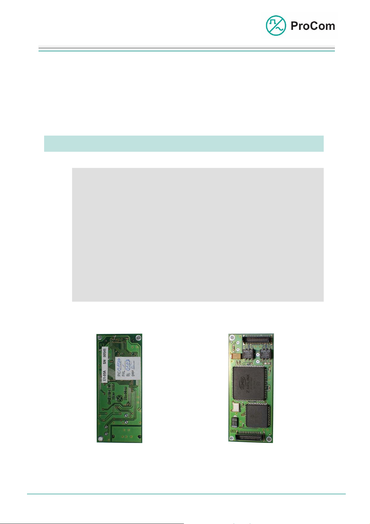
Fig. 1: Front side E1 attachment Fig. 2: Rear side E1 attachment
(L- No. 2.861)
19.03.2009
Page:
1/7
Author: HS Document-No.:
© 2008 ProCom, All rights and technical changes reserved
DB_E1_ 2861_01
Page 2
Data Sheet
U
U
U
E1- Attachment
E1 Attachment for 4FTR and LCPU
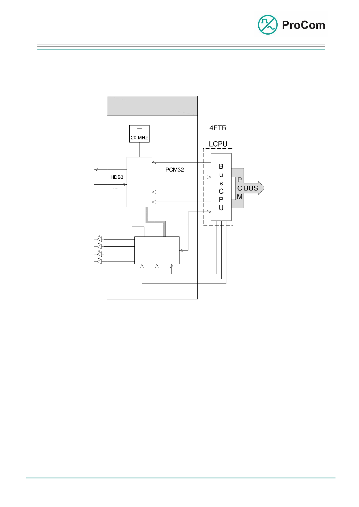
The following block diagram illustrates the general mode of operation of the E1
attachment for the 4FTR or LCPU.
E1 Attachment
or
STI (Digital Input)
E1-
Chip
STI (Digital Input)
FRM
CLK
I
n
d
i
c
a
t
i
o
4FTR/LCP
4FTR/LCP
4FTR/LCP
µ-Prozessor
8k
RST
10MHz
Block diagram E1
The E1 transceiver chip on the E1 attachment is clocked with 20 MHz. The
microprocessor regulates communication with the DVS-21 and the control of the
display LEDs.
The DVS-21s’ own control information (lines, intercom/PA, low frequency (LF)
control) is exchanged bidirectionally between µ-processor and BusCPU of the carrier
card.
The LF wanted signals are managed by the PCM bus (STI, STO, FRM and CLK).
A 2 MBit/s (HDB3) interface forms the connection to the outside world with 30 user
channels and 2 control channels according to ETSI ETS 300 011, ETS 300 166, and
ETS 300 233. The control data can be transmitted to the remote DVS-21 system over
one of two time slots, channel 0 (with 4/5 S-bits) or channel 16 (free signal channel).
In the ICS software a selection can be made which time slot will contain the control
data.
For transmission we differentiate between transparent and framed transmission.
Date:
19.03.2009
Page:
2/7
Author: HS Document-No.:
© 2008 ProCom, All rights and technical changes reserved
DB_E1_ 2861_01
Page 3

Data Sheet
V
V
V
E1- Attachment
E1 Attachment for 4FTR and LCPU
As a rule one of the three following enabling variations is used:
Variation 1: Transmission Using Non-transparent Systems
The signal channel 0 (ZK0) of DVS-21 is transferred in the multiplexer (e.g.
XMP1) to e.g. signal channel 16 (ZK16).
Frame recognition of the DVS-21 is not transferred with it. The transmission
technology uses its own frame recognition.
For the DVS-21 the transfer is virtually transparent.
ariation 1: Signal channel 0 (DVS-21) transferred to channel 16 (PDH-MUX)
Variation 2: Transmission Using Non-transparent Systems
To transmit the control data, now the ZK16 of the DVS-21 is directly used.
ZK0 and hence the frame recognition of the DVS-21 is not transferred with it.
As in variation 1 the transmission technology uses its own frames.
Use of the signal channels is not necessary.
ariation 2: Channel 16 of the (DVS-21) is used as signalling channel
Variation 3: Transmission Using Transparent Systems
The 32 PCM channels of the E1 attachment of the DVS-21 are forwarded
transparently without being altered (e.g. radio relay, Modem, MS1/4, ...).
The use of ZK0 or ZK16 to signal is arbitrary.
ariation 3: Transparent transmission using radio relay system
Date:
19.03.2009
Page:
3/7
Author: HS Document-No.:
© 2008 ProCom, All rights and technical changes reserved
DB_E1_ 2861_01
Page 4

Data Sheet
E1- Attachment
E1 Attachment for 4FTR and LCPU
Clock Synchronization
If one connects independent systems over E1, transmission errors are to be
expected because of the unsynchronized clocking. An input buffer on the E1
attachments establishes a controlled frame slip.
This results in loss of a sampled value and goes unnoticed in purely voice
applications.
Control data is reconstructed by the data link layer.
To optimize the system performance synchronization should be done if possible.
Synchronization is done by the CPU1.
The DVS-21 can be combined together into a group in various ways.
- DVS-21 master / slave operation
Example 1: Clock extraction from transmission network (e.g. railway network). All devices are in slave mode.
Multiple DVS-21 systems are combined into a group. Here one system
must be designated as master to which the others synchronize.
- Synchronize external clock (T3)
Example 2: Clock extraction from a DVS-21. One device is master, the others are in slave mode.
Two DVS-21 systems are combined together over e.g. a multiplexer (e.g.
XMP1) over a transmitting network. The devices synchronize to the
external clock T3.
Date:
19.03.2009
Page:
4/7
© 2008 ProCom, All rights and technical changes reserved
Author: HS Document-No.:
DB_E1_ 2861_01
Page 5

Data Sheet
p
r
(
y)
(
y)
E1- Attachment
E1 Attachment for 4FTR and LCPU
- SDH/PDH master / DVS-21 slave operation
Example 3: Clock extraction from a DVS-21. One device is master, the others are in slave mode.
Two DVS-21 systems are combined together over a modem line and an XMP1. One
DVS-21 generates the clock signal to which the XMP1 and the second DVS-21
synchronize.
The clocking concept is controlled by the CPU1 in each DVS-21. In order for the
system to synchronize to an external clock signal or an HDB3 signal all that is
required is a jumper on the backplane.
The Symbols on the Front Plate and their Meaning (4FTR / LCPU):
The System Blinker
Addressing from processor taking place
I/O Input/Output
BUS output works as push-push operation with the system blinker
BUS in
ut works as push-pull operation with the system blinke
On LF Connection Established
A minimum of one of 30 possible LF connections has been
established
card set related displa
Al No Receiver Found (No Connection)
(card set related display)
Receiving: Data Frame to E1 Interface
card set related displa
Date:
19.03.2009
Page:
5/7
Author: HS Document-No.:
© 2008 ProCom, All rights and technical changes reserved
DB_E1_ 2861_01
Page 6

Data Sheet
(
y)
E1- Attachment
E1 Attachment for 4FTR and LCPU
Sending: Data Frame from E1 Interface
card set related displa
Technical Data:
Operating Voltage: +/-5 V (control)
Idle Current (48 V): 19 mA / E1
Idle Current (+5 V): 115 mA / per E1
Idle Current (-5 V): 0 mA
Operational Current (+5 V): 118 mA / pro E1
Operational Current (- 5V): 0 mA
Interface: 2 MBit/s (HDB3 code according to G.703)
Standards: ETSI ETS 300 011, ETS 300 166, ETS 300 233
Temperature Range: 0 °C to 45 °C
Weight (4FTR/LCPU): 155 g
Date:
19.03.2009
Page:
with 30 PCM user channels and 2 HDLC control
channels
6/7
Author: HS Document-No.:
© 2008 ProCom, All rights and technical changes reserved
DB_E1_ 2861_01
Page 7

Data Sheet
E1- Attachment
E1 Attachment for 4FTR and LCPU
Weight (E1 attachment): 20 g per attachment
Installation height (4FTR/LCPU): 3HE
Installation Width (4FTR/LCPU): 6TE
Dimensions (E1 Attachment): 34 mm x 80 mm (height x width)
Number of Attachments: Up to 4/1 attachments
per 4FTR/LCPU
E1 Attachment
E1-
C
a
Chip
l
l
S
t
a
t
I
n
d
4FTR/LCP
i
c
a
t
i
o
i
o
n
10MHz
8k
Date:
19.03.2009
Page:
7/7
© 2008 ProCom, All rights and technical changes reserved
Author: HS Document-No.:
DB_E1_ 2861_01
 Loading...