

Page 1
Data Sheet
DSS1
Digital Speech Memory Module
DSS1
Digital speech memory module
with RAM and flash memory banks
At a Glance:
• 6 memory addresses for speech recording:
• Write protection feature for speech memory
• Ringing tone detector, e.g. for railway radio
• Synchronisation mode for redundant systems
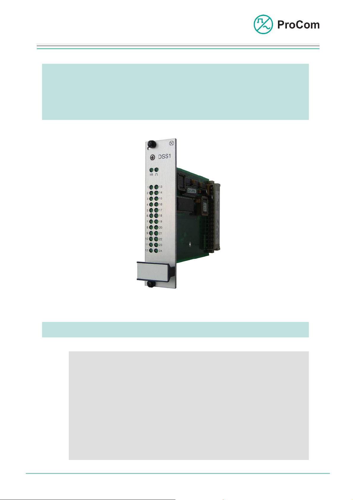
Fig. DSS1 (L- No. 2.600)
- Up to 8 banks in RAM memory (volatile)
- Up to 8 banks in flash memory (permanent)
Date: 13.03.2009 Page:
1/9
© 2008 ProCom, All rights and technical changes reserved
Author: HS Document-No.:
DB_DSS1_2600_01
Page 2
Data Sheet
r
DSS1
Digital Speech Memory Module
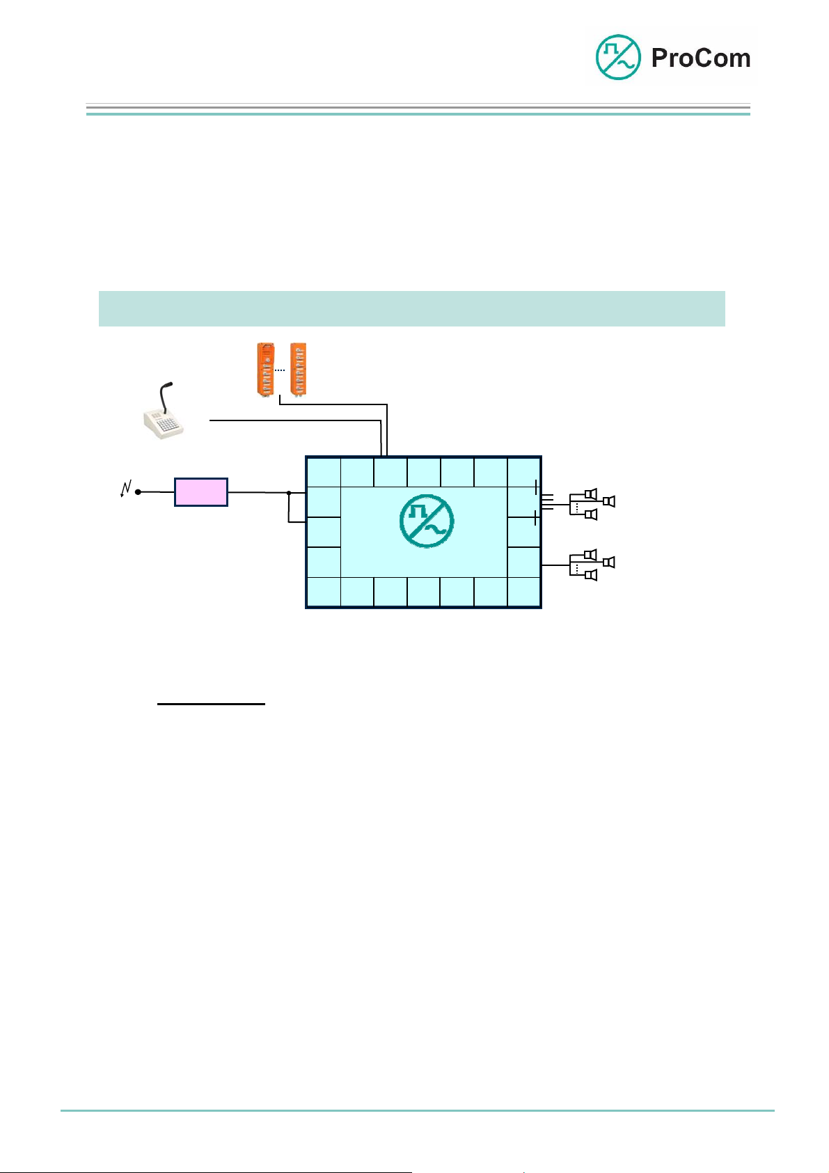
The module DSS1 makes it possible to save recurring verbal announcements and
to output them on call stations and loudspeaker circuits.
For this there are eight memory banks available each on RAM and flash chips.
The module has four independent sets which can all be run in different modes of
operation. This way different functions can be realized on a DSS1.
Each set can simultaneously access each of the 2 x 8 memory banks.
Application Description:
WPS-04
WPS-08
DTA-012 -030/ -048/ -066/ -084/ -114
Radio
Radio
module
Application example for the DSS1 with PA and intercom systems
The
DSS1 module can be used as speech memory in all DVS-21 applications in
which a minimum of a call station or a loudspeaker circuit (LK) are included.
The DSS1 module is used, for example, as ringing tone detector for switching on of
radio modules at Deutsche Bahn AG. Here preset sound frequencies are detected
and correspondingly interpreted.
2DA
CPU1 4NSASV01
4NPA
24LI
DVS-21
DSS1
TG01
4LSL
V100
V100
V100
Disaste
LK2 .. 5
LK1
LS 1
LS n
Loudspeaker monitor
LS 1
LS n
LS 2
LS 2
Date: 13.03.2009 Page:
2/9
Author: HS Document-No.:
© 2008 ProCom, All rights and technical changes reserved
DB_DSS1_2600_01
Page 3
Data Sheet
DSS1
Digital Speech Memory Module
Function Description:
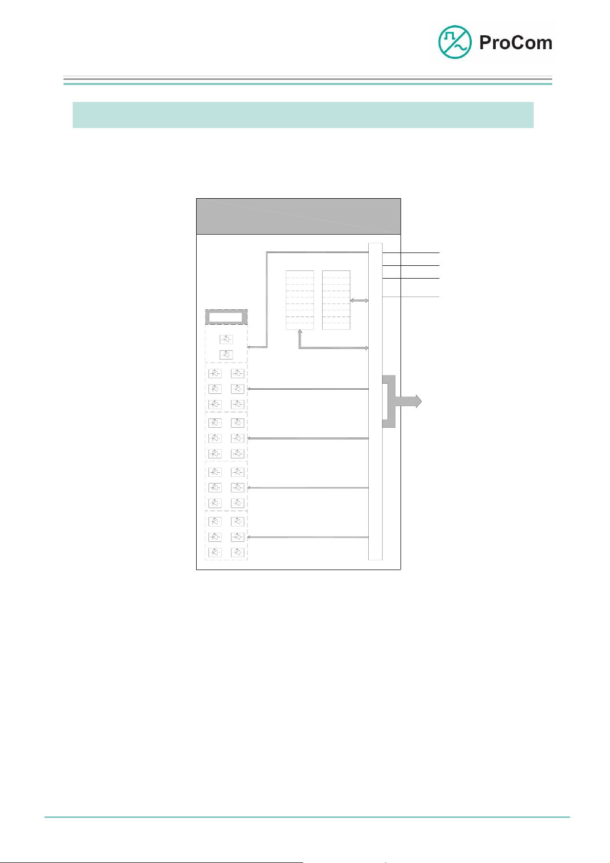
The principle functions are illustrated in the following block diagram.
DSS1
+5V
GND
-5V
KS
BUS
Anzeige
Indication
System-
blinker
I/O
LED 01
LED 13
S
S
a
LED 02
LED 14
e
t
z
t
LED 03 LED 15
1
1
LED 04 LED 16
S
S
a
LED 05
LED 17
e
t
t
z
LED 06 LED 18
2
2
LED 07 LED 19
S
S
a
LED 08 LED 20
e
t
t
z
LED 09 LED 21
3
3
LED 10 LED 22
S
S
a
LED 11 LED 23
e
t
z
t
LED 12 LED 24
4
4
FLASH RAM
Bank 1
Bank 2
Bank 3
Bank 4
Bank 5
Bank 6
Bank 7
Bank 8
Bank 1
Bank 2
Bank 3
Bank 4
Bank 5
Bank 6
Bank 7
Bank 8
S
C
t
O
e
u
N
P
e
C
T
M
r
R
u
O
n
L
g
Block diagram DSS1
The DSS1 consists essentially of a control unit and the RAM and the flash chips.
The module communicates over the PCM bus on 8 of 64 traffic channels (VKW).
Here the following allocation applies:
• Set 1 low frequency: Recording VKW 26 and
playback VKW 22
• Set 2 low frequency: Recording VKW 27 and playback VKW 23
• Set 3 low frequency: Recording VKW 28 and playback VKW 24
• Set 4 low frequency: Recording VKW 29 and playback VKW 25
Date: 13.03.2009 Page:
3/9
© 2008 ProCom, All rights and technical changes reserved
Author: HS Document-No.:
DB_DSS1_2600_01
Page 4

Data Sheet
DSS1
Digital Speech Memory Module
The module is available in two variations which only differ in terms of their software:
- Ringing tone detector
- Speech memory
Variation "Ringing tone detector":
This variation is currently in use at the Deutsche Bahn AG and serves to
switch on radio modules.
Basic arrangement of a DVS-21 for ringing ton analysis
The DSS1 checks cyclically whether a signal is pending from the radio module
on the low frequency line. If a radio subscriber sends a call signal, the frequency is determined from it internally and compared to the three values
stored in the EPROM. Each of these frequencies is allocated to a line. When
there is a match then the corresponding line is sent to the DVS-21 and the
right DVS-21 subscriber is called.
In order to make a connection between the DVS-21 subscriber and the radio
module (and thus the corresponding radio subscriber) the radio module needs
a control line as switch criteria. This is sent over the 24LI with the pressing of
the appropriate range button on the call station, regardless where the connection request originated. The connection is only terminated after the delete button is pressed or after a timeout. To speak, the DVS-21 subscriber must keep
the speaking button pressed, and to listen, let go again.
Optionally the sending of a free line signal and a busy signal can be selected
in the configuration software (ICS). If the subscriber being called is currently
speaking, a short signal is sent twice, otherwise a long signal is sent. Furthermore the limit values of the ringing tone (level and frequency) can be changed
in the ICS software.
Date: 13.03.2009 Page:
4/9
© 2008 ProCom, All rights and technical changes reserved
Author: HS Document-No.:
DB_DSS1_2600_01
Page 5

Data Sheet
DSS1
Digital Speech Memory Module
The following frequencies are available per default:
1520 Hz
1750 Hz
2135 Hz
Other frequencies are possible for special cases.
Variation "Speech Memory":
In this variation, three further modes of operation can be selected in the configuration software:
- Speech Memory
- Sync Master
- Sync Slave
The features on the card depend on the mode of operation.
Mode of Operation "Speech Memory"
In this mode of operation texts can be recorded on one or several banks (up
to 60s for one text). Here the beginning and end of a speech recording are
precisely defined in terms of time, and public address is terminated when
the text ends.
The texts or tones are recorded in analogue form through a 4NSA on the
DSS1.
The RAM memory is designed for recurring announcements over a short
period of time. Texts can be recorded directly through a ProCom call station.
These are retained until the DVS-21 is switched off or until new texts are recorded over them.
Recording on the flash memory can only be done with a detour over the
RAM chip. It is possible to write announcements from the RAM directly into
the flash memory. The memory content of the flash chip is retained, however, also after the DVS-21 is switched off.
The option "write protection" can be activated in order to prevent unintentional deletion of the flash memory.
The memory times are distributed as follows:
RAM
Flash
Flash
Flash
Table 2: Examples of memory distribution
Memory
Type
volatile 7.5 s 8 60 s
permanent 7.5 s 8 60 s
- „ -
- „ - etc. 6 - „ -
Time /
Bank
1 x 15 s
6 x 7.5 s
Number of
Banks
7 - „ -
Total Time
Date: 13.03.2009 Page:
5/9
© 2008 ProCom, All rights and technical changes reserved
Author: HS Document-No.:
DB_DSS1_2600_01
Page 6

Data Sheet
DSS1
Digital Speech Memory Module
Modes of Operation "Sync Master" and "Sync Slave"
A redundant public address system can be built with two DVS-21 systems in
order to ensure adequate public address capabilities for possible disruptions.
Example: A redundant DVS-21 system
To do this the loudspeaker circuits (LK) are arranged in an alternating way with
the loudspeakers of system A and B (LK 1A / LK 1B and LK 2A / LK 2B) in order to ensure adequate public address capabilities in the case of a disruption.
Announcements are triggered or made e.g. through or using a call station in
parallel operation. Because of running times, output through the loudspeakers
in both systems can become superimposed and unintelligible.
To solve this there is an additional synchronisation line between the two
DVS-21 systems (4NSA – 4NSA).
The DSS1 of the first system is set to the mode "Sync Master" and that of the
second system to the mode "Sync Slave". A 1 kHz signal is continuously
transmitted by the master. This signals operation-ready status to the slave system. If an announcement is triggered, the master simultaneously transmits a 2
kHz signal together with the announcement and the slave system simultaneously begins the announcement.
These modes of operation are configured as option in the ICS.
Date: 13.03.2009 Page:
6/9
© 2008 ProCom, All rights and technical changes reserved
Author: HS Document-No.:
DB_DSS1_2600_01
Page 7

Data Sheet
p
r
DSS1
Digital Speech Memory Module
The Front Plate Symbols and their Meaning:
The System Blinker
Addressing from processor taking place
I/O Input/Output
BUS output works as push-push operation with the system
blinker
BUS in
01 - 03 Status Display Set 1
13 - 15
04 - 06 Status Display Set 2
16 - 18
07 - 09 Status Display Set 3
19 - 21
10 - 12 Status Display Set 4
22 - 24
LED Displays (depending on the set):
ut works as push-pull operation with the system blinke
1
2
3
Set 1
Date: 13.03.2009 Page:
13
14
15
4
5
6
Set 2
16
17
18
7
8
9
Set 3
19
20
21
10
11
12
Set-related arrangement of the front plate LEDs
7/9
Author: HS Document-No.:
© 2008 ProCom, All rights and technical changes reserved
22
23
24
Set 4
DB_DSS1_2600_01
Page 8

Data Sheet
DSS1
Digital Speech Memory Module
LED Illumination
Function Description
Delete
Flash
Delete flash
Delete
Flash
Delete terminated with success
Recording
Transfer terminated
RAM Æ Flash
Recording
RAM Æ Flash
Inactive
Special Cases
Recording
RAM Æ Flash
Recording
RAM Æ Flash
Recording
RAM Æ Flash
If this pattern appears immediately following the copy
command, there is no flash in
the socket or the flash is defective
When this pattern appears,
then the flash was delivered
write protected. Either use a
new flash or remove write protection in a special copy device.
When this pattern appears
then the flash has been write
protected through ICS. The
respective option checkmark
must be removed.
Date: 13.03.2009 Page:
8/9
© 2008 ProCom, All rights and technical changes reserved
Author: HS Document-No.:
DB_DSS1_2600_01
Page 9

Data Sheet
DSS1
Digital Speech Memory Module
Technical Data:
Operating Voltage: +/-5 V (control)
Operational Current (+5 V): 6 mA
Weight: 300 g
Installation Height: 3HE
Installation Width: 6TE
Date: 13.03.2009 Page:
9/9
© 2008 ProCom, All rights and technical changes reserved
Author: HS Document-No.:
DB_DSS1_2600_01
 Loading...