

Page 1
Data Sheet
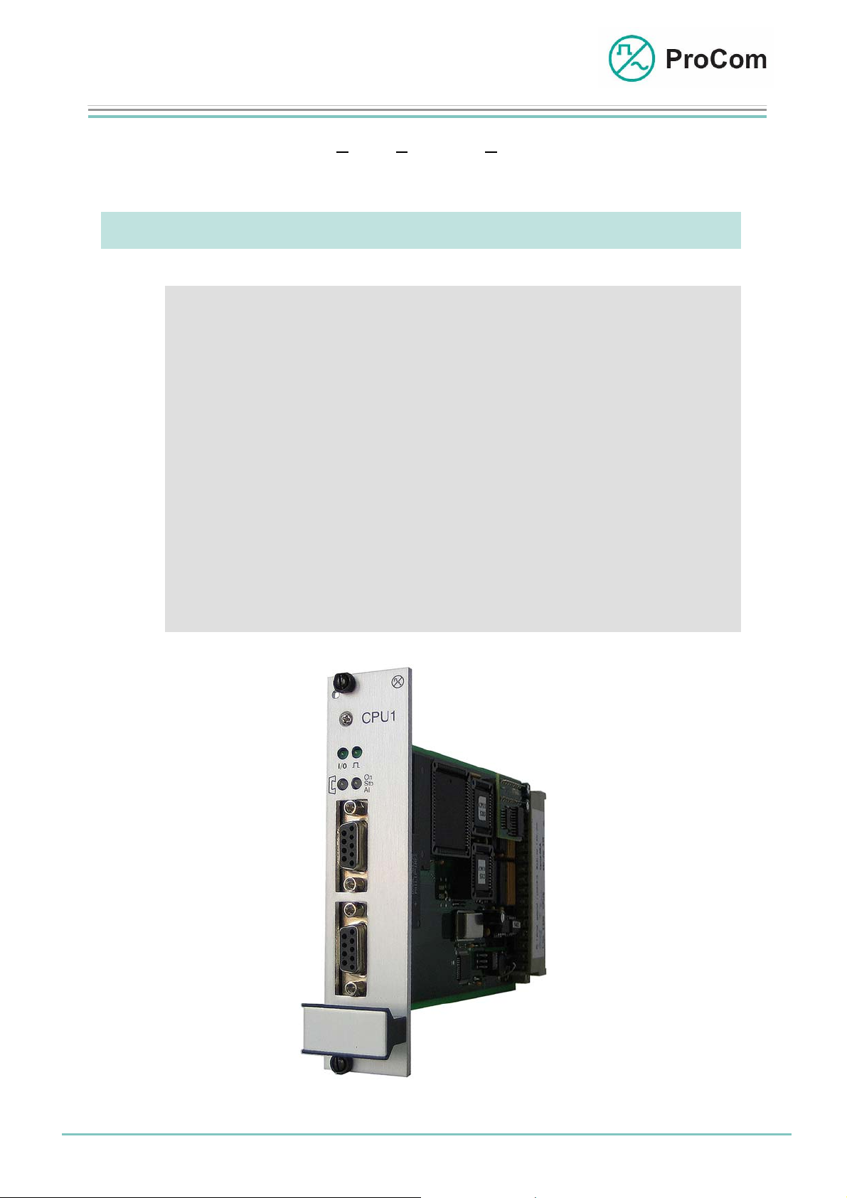
CPU1
Processor Module
The processor module, CPU1 (Central Processing Unit) administers the configuration
(programmes and parameters) of the DVS-21 system. It controls the interaction
between the external interfaces, the slide-in modules and the PCM bus.
At a Glance:
• Control and monitoring of DVS-21 functionality
• Central parameterization of all system modules
• 4 system configurations on 4 memory banks, switchable
• External clocking over 2 MBit/s (HDB3) or 2 MHz
• DVS-21 system clock, can be synchronized to DCF77
• Local and remote malfunction signals
• Configurable over a serial V.24 interface
• Configuration software runs on windows, also runs offline
Fig. CPU1 (L- No. 2200)
Date:
13.03.2009
Page:
1/4
© 2008 ProCom, All rights and technical changes reserved
Author: HS Document-No.:
DB_CPU1_2200_01
Page 2
Data Sheet
CPU1
Processor Module
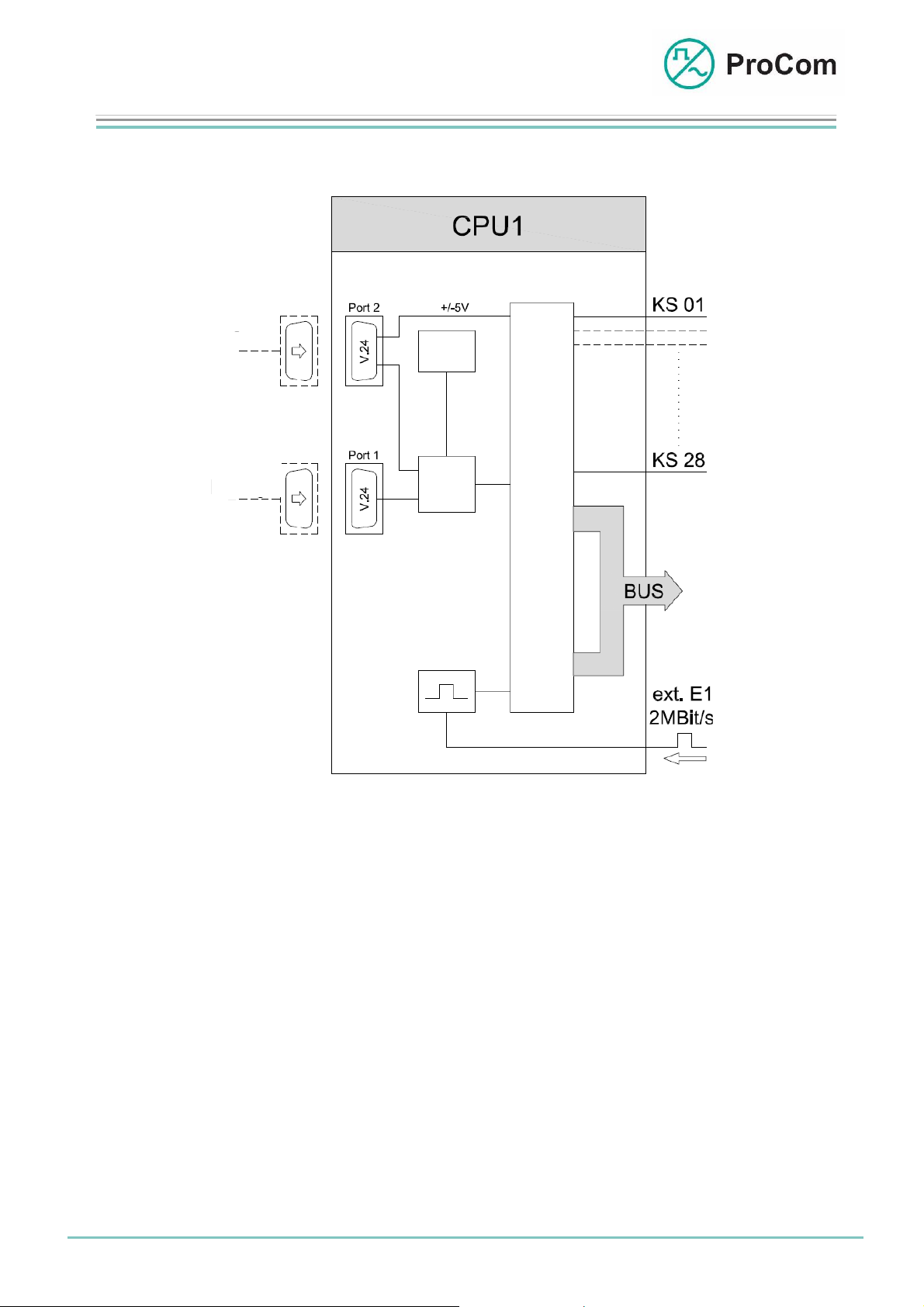
The principle functions are illustrated in the following block diagram.
DCF77
RTC
Config.
CPU
Clock
Sync.
Block diagram CPU1
The processor module administers up to 28 modules of a DVS-21 system.
Communication with the modules is done through the bus system of the backplane.
- Card select (KS) 1 - 28: Addressing of the modules in the DVS-21 system
- PCM bus: 48 PCM user channels (duplex)
A standby processor can be fitted on a special backplane variation as option. If the
active processor fails an automatic switching over to the standby CPU1 takes place.
The internal clock generator makes system clock signals available for the modules,
the PCM bus and the external interfaces.
It is possible to use an external 2 MBit/s, HDB3 signal (T2) or a 2 MHz clock signal
(T3) for clock extraction. A clock signal thus generated is available to all systems
belonging to a DVS-21 group.
The CPU1 works with the operating system “DVS-xx”. 2 firmware versions can be
stored and arbitrarily activated.
Date:
13.03.2009
Page:
2/4
© 2008 ProCom, All rights and technical changes reserved
Author: HS Document-No.:
DB_CPU1_2200_01
Page 3
Data Sheet
CPU1
Processor Module
The configuration software “ICS x.xx” offers the possibility of transferring or readingout of up to 4 system configurations to/from the CPU1 over the serial V.24 interface
(port 1) (Userbank 1 – Userbank 4).
The internal DVS-21 system clock can be updated by an external DCF77 receiver. If
several DVS-21 systems are connected together as group then the synchronization
of the system clocks of the systems in the group can be done with only one DCF77
receiver.
System configuration as well as the connecting of the DCF77 receiver is done over
two potential-separated serial V.24 interfaces.
- Port 1: Connecting of a PC with the configuration software ICS
(also possible from a remote location over modem)
- Port 2: Connection of a radio controlled clock (DCF77) to adjust system
time (beginning with hardware version 6.01)
As long as the modem connection for remote configuration of the DVS-21 is
used, communication with the DCF77 receiver is interrupted.
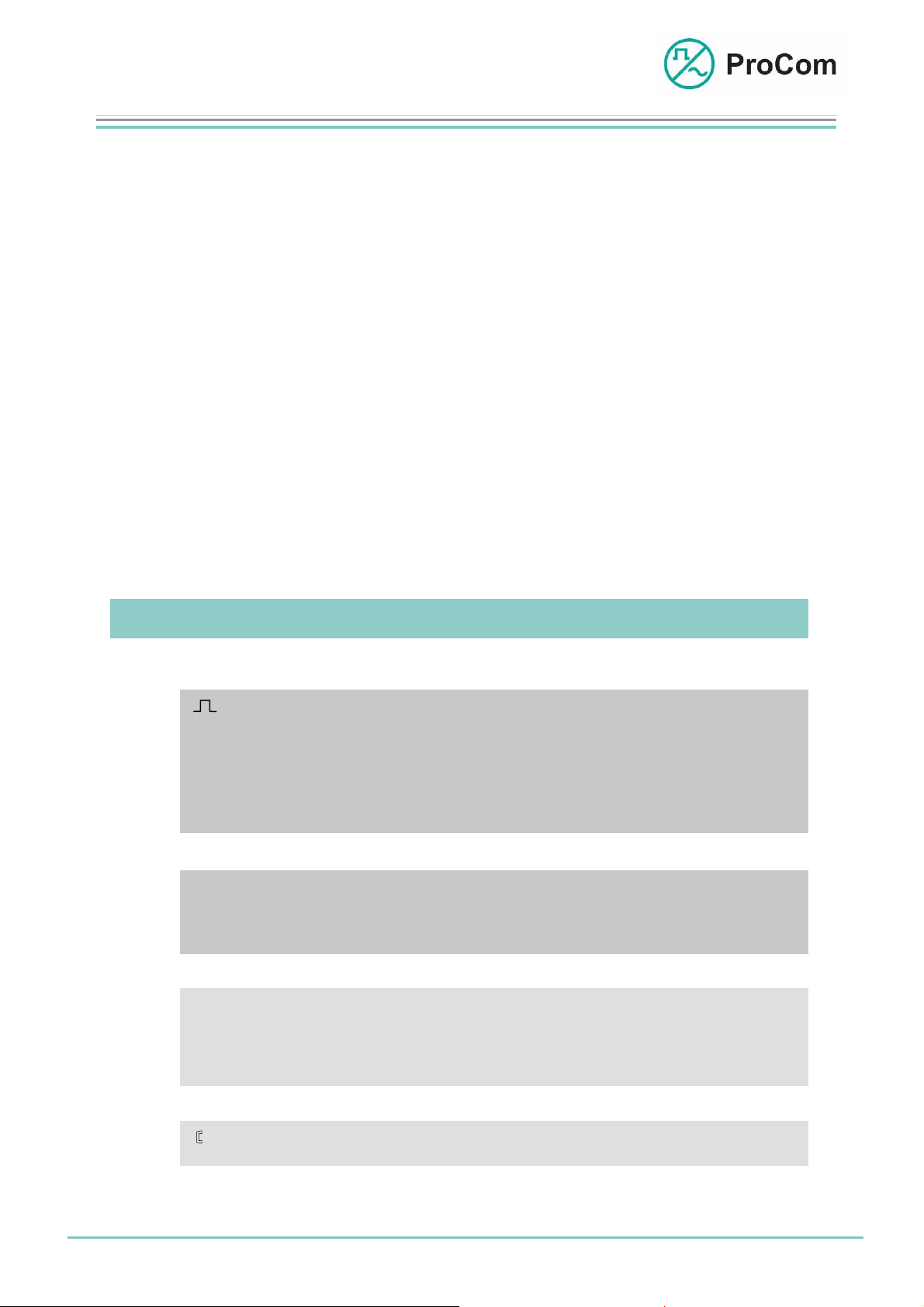
The Front Plate Symbols and their Meaning:
The System Blinker
Addressing from processor taking place
The CPU1 status can be determined by the blinking behaviour
• Initialization of the system
• System OK
• Card select correctly attached
I/O Input/Output
BUS output works as push-push operation with the system blinker
BUS input works as push-pull operation with the system blinker
On/ Status Display
Stb/ green: Æ Processor operational
Al yellow:Æ Standby processor operational
red: Æ Error notification (alarm)
Telephone interface active (optional)
Date:
13.03.2009
Page:
3/4
© 2008 ProCom, All rights and technical changes reserved
Author: HS Document-No.:
DB_CPU1_2200_01
Page 4

Data Sheet
CPU1
Processor Module
Technical Data:
Operating Voltage: +/-5 V (control)
Operational Current (+5 V): 200 mA
Operational Current (-5 V): 4 mA
Interfaces: • 28 control outputs (card selection) for
(V24 to backplane) addressing of the DVS-21 modules
Interfaces: • Port1: Serial interface for PC for system
(V.24 on the front) configuration
• Port2: connection for DCF 77 (radio controlled
clock)
Temperature Range: 0 °C to 45 °C
Weight: 300 g
Installation Height: 3HE
Installation Width: 6TE
• 48 PCM user channels
Date:
13.03.2009
Page:
4/4
© 2008 ProCom, All rights and technical changes reserved
Author: HS Document-No.:
DB_CPU1_2200_01
 Loading...