

Page 1
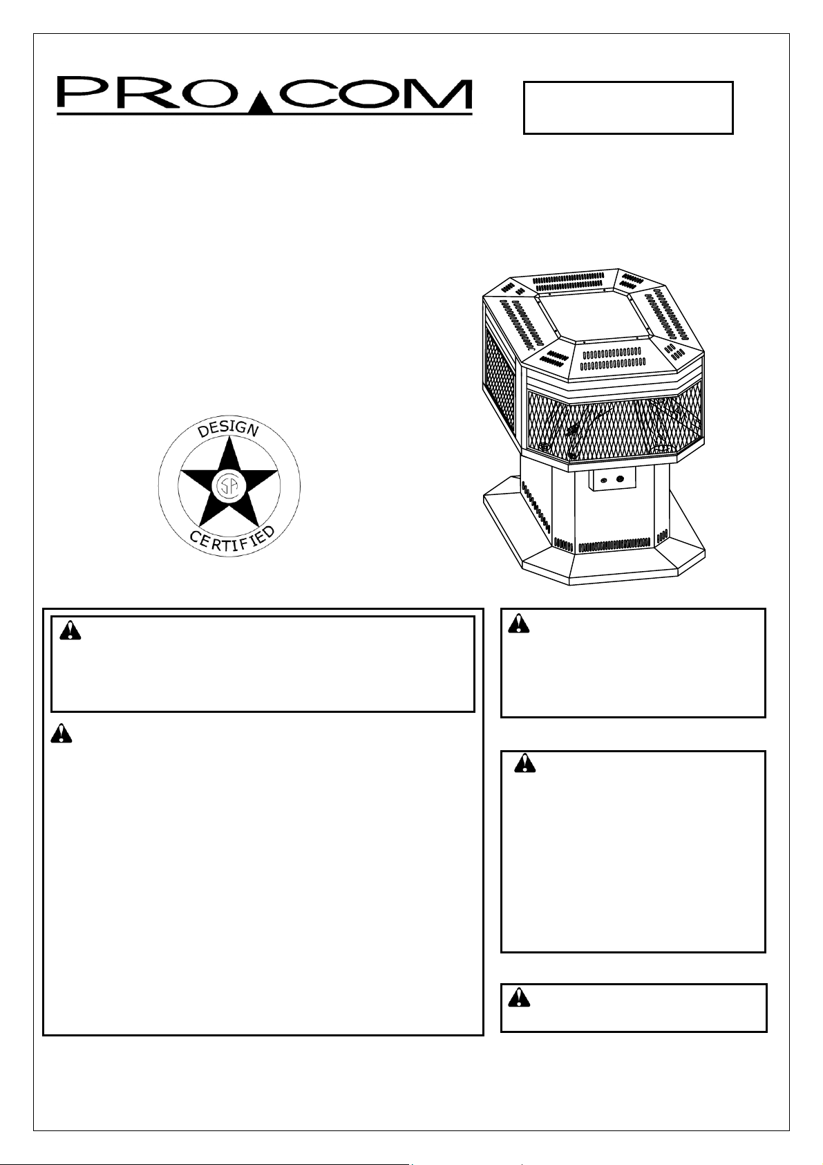
OUTDOOR GAS
FIREPLACE
OWNER’S OPERATION AND INSTALLATION MANUAL
AL500HYLA
50,000 BTU/Hr
Manually Controlled
WARNING: If the information in this manual is
not followed exactly, a fire or explosion may result
causing property damage, personal injury, or loss
of life.
FOR YOUR SAFETY :
Do not store or use gasoline or other flammable
vapors and liquids in the vicinity of this or any other
appliance.
WHAT TO DO IF YOU SMELL GAS:
Do not try to light any appliance.
Do not touch any electrical switches; do not use
any phones in your building.
Immediately call your gas supplier from a
neighbor’s phone, follow the gas supplier’s
instructions.
If you cannot reach your gas supplier, call the fire
department.
Installation and service must be performed by a
qualified installer, service agency or the gas supplier.
IMPORTANT: Read this
owner's manual carefully and
completely before trying to
assemble, operate, or service
this heater.
WARNING: Improper
installation, adjustment,
alteration, service, or
maintenance can cause injury
or property damage. Read the
installation, operating and
maintenance instructions
thoroughly before installing or
servicing this equipment
WARNING: FOR Outdoor Use
Only.
Save this manual for future reference.
Installer: Leave this manual with customer.
Page 2
SAFETY INFORMATION
2
-
1. Check the heater completely and thoroughly for
damage. DO NOT run a damaged heater.
2. DO NOT alter the heater or operate a heater that
has been modified from its original condition.
3. Use only propane gas.
4. Use only vapor withdrawal propane gas. If any
question, contact your LP dealer.
5. Do not use this heater as a wood-burning heater.
Use only the logs provided with the heater.
6. Inspect hose assembly before each use of the
heater. If there is excessive abrasion or hose is cut,
STOP USING HEATER! Replace with a new hose.
7. This heater is for outdoor use only. Even so make
sure that there is ample fresh air ventilation. Do not
use in buildings, garages or other enclosed spaces.
8. In the event that gas odor is detected,
IMMEDIATELY STOP operation until gas supply
has been located and corrected.
9. Do not place the heater where directly exposed to
water spray, rain, dripping water or wind.
10. Maintain minimum clearance to people or normal
combustible material (like paper) of 2 feet.
11. Place heater on a stable, level surface.
12. You must operate the heater with the heater
screen in place. Make sure heater screen is in
place before running heater.
13. This heater is designed to be smokeless. If logs
ever appear to smoke, turn off heater and call a
qualified service person. Note: during initial
operation, slight smoking could occur due to log
curing and heater burning manufacturing residues.
14. Do not attempt to move, handle or service while
heater is hot or in operation.
15. Use only in accordance with local codes or, in the
absence of local codes, with the National Fuel Gas
Code ANSI223.1-1996.
16. Do not hang or attach clothing or any other
flammable materials on or near the heater.
17. Carefully supervise young children when they are
in the vicinity of heater.
18. Heater becomes very hot while running. Keep
children and adults away from hot surface to avoid
burns or clothing ignition.
19. Installation and repair should be done by a
qualified service person. The appliance should be
inspected before use and at least annually by a
qualified service person. More frequent cleaning
may be required as necessary. It is imperative that
control compartment, burners and circulating air
passageways of the appliance be kept clean.
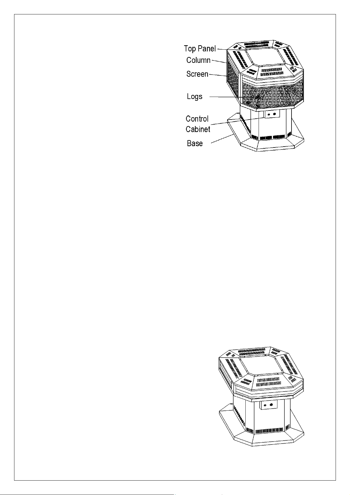
PRODUCT IDENTIFICATION
LOCAL CODES
Install and use heater with care. Follow all local codes.
In the absence of local codes, use the latest edition of
The National Fuel Gas Code, ANSZ223.1, also known
as NFPA54*.
Available from :
American National Standards Institute, INC.
1430 Broadway, New York, NY10018
National Fire Protection Association, INC.
Batterymarch Park Quincy. MA 02269
UNPACKING
1. Remove top inner pack.
2. Slide stove out of carton and set it on the flat floor.
3. Remove protective packaging.(See FIG.2)
4. Remove plastic wrap and carton from MID base.
5. Turn the door knob clockwise, open heater door to
take out log set, Remove all protective plastic wrap.
6. Unwrap log set by cutting plastic ties.
7. Check for any shipping damage. If stove or log is
damaged, promptly inform dealer where you bought
the stove.
Figure
2 AL058-01
shipping fireplace
Page 3
PRODUCT FEATURES
SAFETY PILOT
The heater has a pilot with a safety shutoff system.
The safety pilot is a required feature for outdoor
heaters. It shuts off the heater if flame is extinguished
by rough wind.
PIEZO IGNITION SYSTEM
This heater has a piezo igniter. This system requires
no matches, batteries, or other sources to light heater.
INSTALLATION
TOOLS REQUIRED:
●
Philips screwdriver
●
Wrench
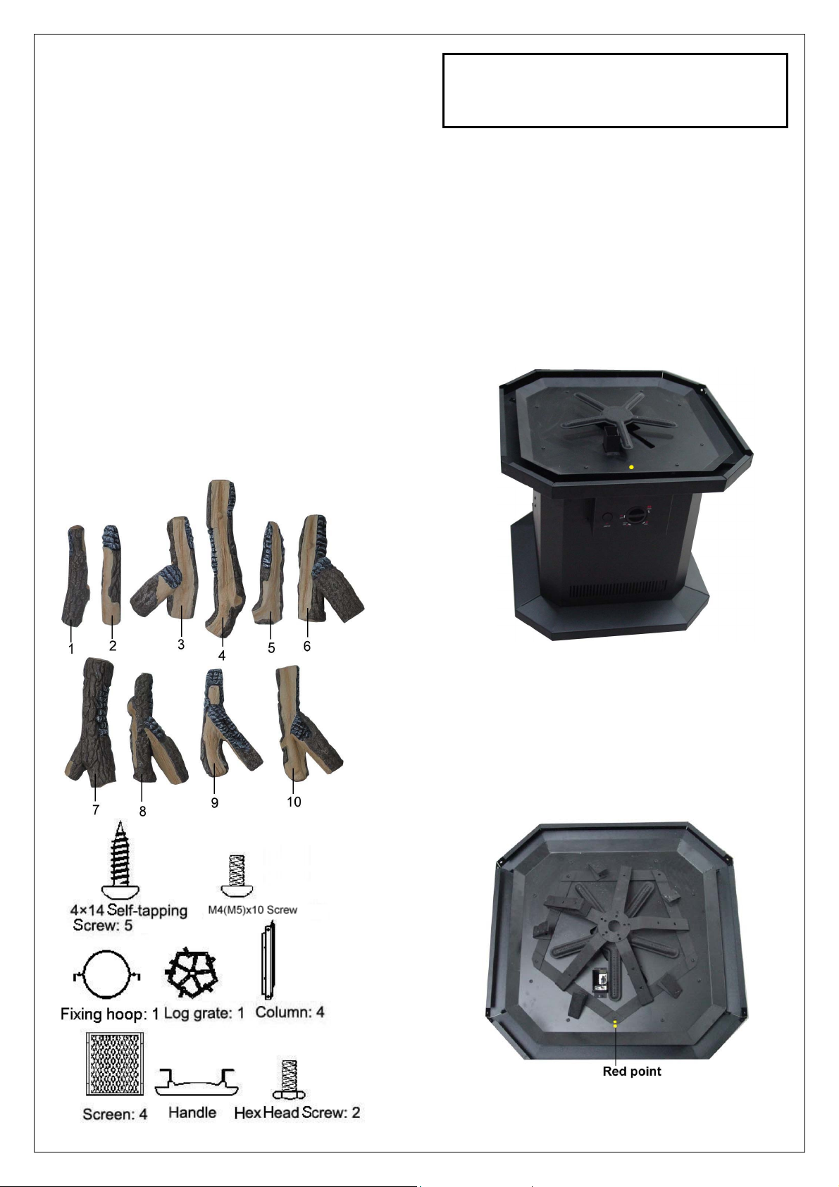
Check if you have the items listed below before
installation.
●
Logs: 10 ● 4×14 self-tapping screw: 5
●
M4×10 screw: 32 ● M5×10 screw: 4
●
Column: 4 ● Log grate: 1
●
Fixing hoop: 1 ● Hex head screw: 2
●
Handle: 1 ● Screen: 4
3 AL058-01
Caution: Some of the steel edges may
be sharp. Please use caution when
assembling the unit.
INSTALLATION INSTRUCTIONS:
1. Remove grate out of base and set flat on floor.
2. Take log foam package out of base. Please note
each log fits the number marked on foam package.
3. Unscrew the 16 screws that attach the top panel
and the middle base with short columns. Remove
top panel and short columns. Then set flat on the
floor. (See FIG. 3)
Note: Short Columns and Self-tapping Screws are
used for packing only.
Figure 3-Burner fixing plate
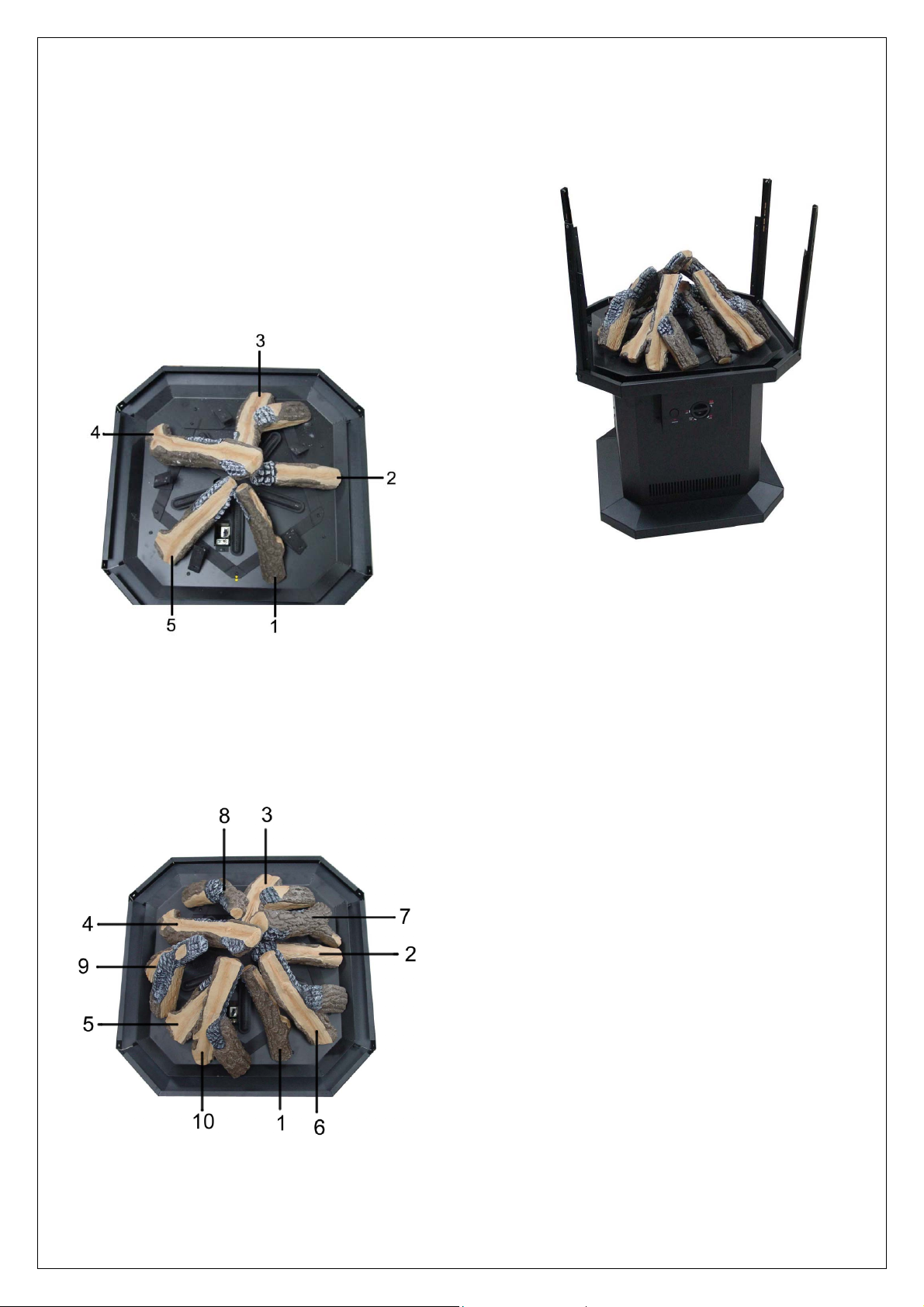
4. Place grate on burn plate. Make sure to line up the
red mark and five holes of grate with that of burn
plate. Then secure grate to burn plate with 5 4×
14 Self-tapping Screws. (See FIG.4)
Figure 4-Place grate on burn plate
Page 4
INSTALLATION INSTRUCTIONS
5. Install logs 1,2,3,4,5 by inserting each log
screw into holes of corresponding grate
branch . Make sure each log is placed in
proper sequence.(See FIG 5.)
Note: If the log is too loose or the screw can’t be
pulled down after inserting the log screw, screw the
nuts to adjust the clearance between nuts and
logs.
Figure 5-Installing log 1.2.3.4.5
6. Install logs 6,7,8,9,10 as step 5.(See FIG.6)
Continued
Attach the four columns to the burner plate with
7.
M4×10 screws provided. Do not tighten at this
time. (See FIG.7)
Figure 7-Column installation
Figure 6-Installing log 6.7.8.9.10
4 AL058-01
Page 5
8. Set the top panel in place on the columns and
secure with M4×10 screws provided. Do not
tighten at this time. (See FIG.8)
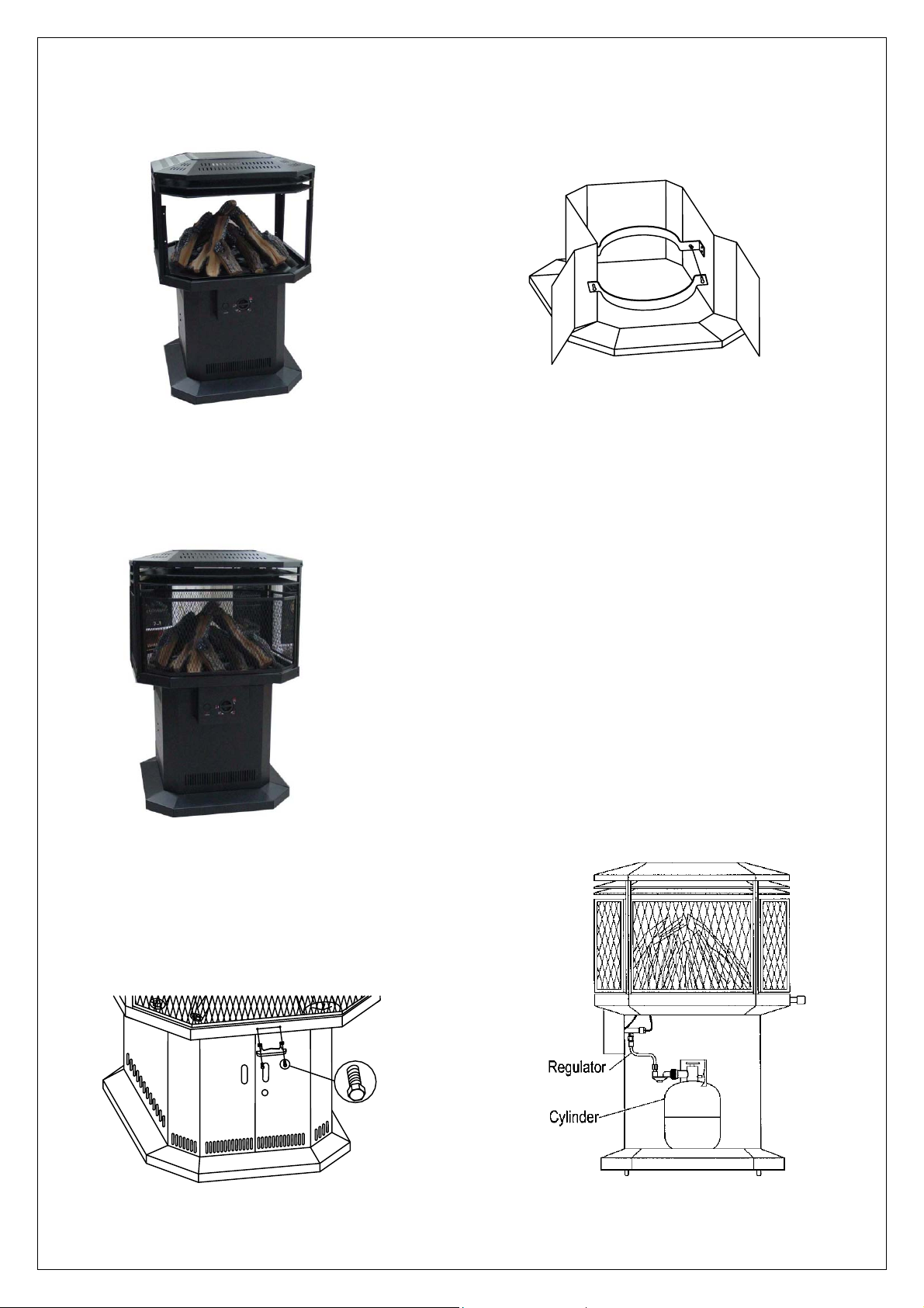
12. From the outer side, use M5×10 screws to
fasten the fixing hoop on the right and left support.
Fasten the other side of the fixing hoop after the
cylinder is in place. (See FIG.11)
Figure 11-The fixing hoop installation
Figure 8-Top panel installation
9. Attach the screens to columns with M4× 10
screws provided. Do not tighten at this time. (See
FIG.9)
Figure 9-Screens installation
10. Tighten the screws of step 8,9,10 to finish
installation.
11. Attach the handle to the middle base with 2 hex
head screws provided. (See FIG.10)
CONNECTING TO GAS SUPPLY
Note: The installer must supply an external regulator
with a hose (with 5/8” nut at one end, and a regulator
at the other end) and a 20# Vertical Acme with OPD
LP cylinder.
1. Turn the door knob clockwise and open heater
door.
2. Remove dustproof wrap from regulator.
3. Set cylinder flat on base compartment (See FIG.12)
4. Connect regulator with cylinder. Tighten with care.
Do not over-pressurize the valve.
5. Before opening gas supply valve, make sure
control knob is in the OFF position. Open gas
supply valve. Apply a mixture of liquid soap and
water to all joints. Do not use an open flame.
Bubbles forming show a leak. Check all
connections for leaks immediately.
Figure 10-Handle installation
5 AL058-01
Figure 12-Cylinder set and pipe
installation
Page 6

CONNECTING TO GAS SUPPLY
Continued
FUEL REQUIREMENTS:
Connect regulator/hose with standard 20-pound
LP cylinder coupler.
Call the LP gas supplier to inspect the cylinder.
Do not use a damaged LP gas cylinder.
Do not use LP gas without proper
decompression.
Do not connect irregular LP gas supply with
heater.
Use only LP gas on this heater. Do not convert to
other gases.
OPERATING HEATER
Continued
TO TURN OFF HEATER:
1. Turn gas control knob to the “OFF” position.
2. If heater is not to be used, shut off cylinder valve.
3. Do not attempt to relight heater within 5 minutes
after the propane cylinder valve has been closed.
RESTART HEATER:
1. Turn gas control knob clockwise to “OFF” position.
2. Wait 5 minutes before restarting.
3. Repeat step 5,6,7.
MAINTENANCE AND STORAGE
CAUTION: It is dangerous to use a damaged
or rusted cylinder.
OPERATING HEATER
This heater is designed for use with LP gas. You may
light the heater directly.
LP gas is heavier than air. If it leaks from joint, it may
sink down to the floor and mix with ambient air to form
a detonable mixture. If you have questions, contact
your LP dealer for instructions or service.
Warning: Fire, burn, inhalation and explosion
hazard. Keep solid combustibles, such as
building materials, paper or cardboard, at safe
clearances from the heater. Never use heater in
the vicinity of gasoline, solvent, paint thinner or
other combustibles.
Caution: When heater runs in the presence of
other people, the user is responsible to properly
offer those present safety precautions and
hazard information.
LIGHTING INSTRUCTIONS:
Follow adaptable lighting instructions. Apply soap
solution to all joints. Bubbles forming show a leak. Do
not use a match or an open flame to detect leak. Light
heater after ensuring that no gas leak exists.
START HEATER:
1. Turn the control valve knob clockwise to the “OFF”
position.
2. Turn the door knob clockwise and open the heater
door.
3. Check all connections as described in the
“Connecting to Gas” section of this manual on
page 5.
4. Fully open the valve on the propane cylinder.
5. Push in gas control knob and turn it to IGN/ON
position. Then Push and release the ignition button
repeatedly until there is a flame at the pilot.
6. Keep control knob pressed in for 30 seconds after
ignition, then release.
7. Turn the burner on to maximum rate and then set
to desired setting or remain on HI.
8. Replace heater compartment door.
1. The Lp-gas supply cylinder to be used must be
constructed and marked in accordance with the
specifications for LP-gas cylinder of the U.S.
Department of transportation.
2. Storage of an appliance indoors is permissible only
if the cylinder is disconnected and removed from
the appliance. Cylinders must be stored outdoors
in a wellventilated area out of the reach of children.
Disconnected cylinders must have threaded valve
plugs tightly installed and must not be stored in a
building, garage or any other enclosed area.
3. The pressure regulator and hose assembly
supplied with the appliance must be used and a
statement that replacement pressure regulators
and hose assemblies must be those specified by
the appliance manufacturer.
4. If the connection to the LP-gas cylinder is other
than Type I, II or III (as described in the Standard
for Cylinder Connection Devices, ANSI
Z21.81/CGA 6.25), the cylinder with its mating
fitting shall be provided by the appliance
manufacturer. Supplying the cylinder may be
accomplished by a method controlled by the
manufacturer that will result in both the appliance
and the cylinder being available at the time of
purchase.
5. The cylinder supply system must be arranged for
vapor withdrawal.
6. The cylinder used must include a collar to protec t
the cylinder valve.
7. Have the heater inspected by qualified service man
before each use or at least annually.
8. Check the POL fitting for any damage before each
use and replace if any damage is found.
9. Turn off cylinder valve when the heater is not to be
used.
6 AL058-01
Page 7

MAINTENANCE AND STORAGE
r
Continued
11. Spiders and insects can nest and live in outdoor
appliances, especially in the burners and orifices.
This will interrupt the normal flow of LP gas to the
heater and can be a very dangerous situation.
Inspect for insect infiltration of burner/orifice when
one of the following occurs:
A. The smell of gas along with predominating yellow
tipping of the burner flames.
B. Heater can not reach desired temperature.
C. Uneven burner flow.
D. Burner makes popping noises d uring n ormal use or
shutdown.
12. When heater to be stored outdoors, detach
connection between LP cylinder and heater.
Remove cylinder from heater and store in
accordance with chapter 5 of the standard for
Storage and Handling of liquified gas.
13. Adopt rainproof cover (provided with the heater) to
avoid rust of heater when not in use.
WARNING: Local codes for installation of propane
systems may vary considerably. Therefore, ask your
local propane supplier for advice on propane system
installation. In the absence of local codes, install in
accordance with Standard for the Storage and
Handling of Liquified Petroleum Gases ANSI/NFPA
58-1995 and National Fuel Gas Code ANSI
Z223.1-1996. Your supplier, fire marshal or library
should have a copy. The propane used must be
arranged for vapor withdrawal. Propane cylinders
must be secured in the upright position to keep them
from falling or being knocked over.
GENERAL INFORMATION
During use, liquid propane in a cylinder vaporizes. As
it vaporizes, the propane cools itself. If this cooling
process lasts too long and proceeds too fast, the
propane temperature and pressure will fall so low that
the heater operation may be improper or even halt.
Often frost forming on the outside of the propane
container warns excessive refrigeration.
Recommendations on how to reduce refrigeration:
A. Provide considerably more propane than you plan
to consume, it’s better to provide twice as much.
B. Fill containers frequently, especially in cold
weather. Never allow propane to fall below
one-third of container capacity.
CLEANING AND MAINTENANCE
CAUTION:
top panel of heater clean. Inspect these areas of
heater before each use. Have heater inspected
yearly by a qualified service person.
WARNING: Shut off heater and let cool before
servicing.
You must keep control areas and
PILOT AND BURNER:
Clean dust with a vacuum cleaner.
BURNER AIR INLET HOLE:
We recommend that you clean the unit every three
months or after 2500 hours operation. We also
recommend that you keep the burner tube and pilot
assembly clean and free of dust. To clean these parts,
we suggest using compressed air no greater than 30
PSI. You can also use a vacuum cleaner in the blow
position. If using compressed air in a can, please
follow the directions on the can. Otherwise, you might
damage the pilot assembly.
1. Shut off the unit, including the pilot. Allow the unit to
cool for at least thirty minutes.
2. Inspect burner, pilot, and primary air inlet holes on
injector holder for dust and dirt. (See FIG.13)
3. Blow air through the ports/slots and holes in the
burner.
4. Check the injector holder again, remove any large
particles of dust and dirt with a soft cloth or vacuum
cleaner nozzle.
5. Blow air into the primary air holes on the injector
holder.
6. In case large clumps of dust have been pushed into
the burner, repeat steps 3 and 4.
Clean the pilot assembly also. A yellow tip on the pilot
indicates dust and dirt in the pilot assembly.
Figure 13-Injector Holde
On Outlet Burner Tube
EXTERIOR:
Use a soft cloth dampened with a mild soap and water
mixture. Wipe the cabinet to remove dust.
LOGS:
If you remove logs for cleaning, refer to installing logs,
Pages 3 and 4 to properly replace logs. Replace logs
if broken or chipped.
MAIN BURNER:
Periodically check all burner flame holes with the
heater running. All slotted burner flame holes should
be open with a yellow flame present. Some burner
flame holes may become blocked by debris or rust,
with no flame present. If so, turn off heater and let
cool. Either remove blockage or replace burner.
Blocked burner flame holes will create soot.
7 AL058-01
Page 8

t
SERVICE INDICATIONS:
A hazardous condition may result if a heater has
been modified or is not functioning properly. When
the heater is working properly:
1. The flame is contained within the heater.
2. The flame is essentially yellow.
3. There is no strong disagreeable odor, eye
burning or other physical discomfort.
4. No smoke or soot exists internal or external to
the heater.
5. No unplanned or unexplained shut down of the
heater occur.
REPLACEMENT
REPLACEMENT PARTS:
Note: Use only original replacement parts. This will
protect your warranty coverage for parts replaced
under warranty.
PARTS UNDER WARRANTY:
Contact authorized dealers of this product. If they
can't supply original replacement part(s) call
PRO-COM's Technical Service Department a
1-877-886-5989 for referral information.
When calling PRO-COM or your dealer, have
ready
Your name
Your address
Model and serial numbers of your heater
How heater was malfunctioning
Type of gas used (propane/LP or natural gas)
Usually, we will ask you to return the defective
part to the factory.
PARTS NOT UNDER WARRANTY:
Contact authorized dealers of this product or Parts Central if
they can't supply original replacement part(s) Call PRO-COM's
Parts Department at 1-877-886-5989 for referral information.
When calling PRO-COM, have ready
Model number of your heater
The replacement part number
ACCESSORIES
Purchase these heater accessories from your local
dealer or Parts Central. If they cannot supply these
accessories call PRO-COM’s Sales Department at
1-877-886-5989 for referral information. You can also
write to the address listed on the back page of this
manual.
SPECIFICATIONS
Btu 50000
Gas Type LP Gas Only
Ignition Piezo
Inlet Gas Pressure* (In. of water)
Maximum 13”
Minimum 11”
Dimensions, Inches (HxWxD)
Stove 42 9/16”x26”x26”
Carton 30 5/16”x27 3/4”x27 3/4”
Weight, Lbs
Stove 141
Shipping Weight 163
* For purpose of shipment adjustment.
TROUBLESHOOTING
OBSERVED PROBLEM
Burner does not light.
When ignitor buttons pressed in, there
is no spark at safety Pilot.
Burner fire does not last.
8 AL058-01
POSSIBLE CAUSE REMEDY
1. Air in gas lines.
2. Inlet gas pressure is too low.
3. Gas supply turned off.
4. Air passageway on heater blocked.
5. Burner orifice clogged.
6. Control knob not in ING/ON position.
7. Control knob not fully pressed in while
in ING/ON position.
1. Ignitor electrode positioned wrong.
2. Ignitor electrode broken.
3. Broken ignitor cable.
4. Ignitor electrode not connected to
ignitor cable.
1. Damaged thermocouple.
2. Thermocouple electrode
corrosion.
3. Damaged control valve.
4. Control knob not pressed long
enough.
5. Thermocouple connection
loose at control valve.
6. Pilot flame not touching
thermocouple.
1. Continue holding down control knob.
Repeat igniting operation until air is
removed.
2. Check gas pressure.
3. Fully open gas supply.
4. Check air passageway.
5. Clean burner.
6. Turn control knob to ING/ON position.
7. Press down control knob.
1. Reposition ignitor.
2. Replace ignitor.
3. Replace ignitor cable.
4. Connect electrode to ignitor cable.
1. Replace thermocouple.
2. Clean thermocouple electrode.
3. Replace control valve.
4. After ODS/pilot lights, keep control
knob pressed in for 30 seconds.
5. Hand tighten connection or replace
thermocouple.
6. Contact qualified service man.
Page 9

PARTS LIST
HP500MA
This list contains replaceable parts used in your heater. When ordering parts, follow the
instructions listed under Replacement Parts on page 7 of this manual.
KEY
NO.
1
2 AB29001
3
4
5
6
7
8
9
10
11
12
PART
NUMBER
AB01001
AB29002
AL002-01
AL009-01
AL01002
AL033-01
AL013-01
AL011-01
AB01004
AB01005
AL071-01
DESCRIPTION QTY.
Top Panel
Mesh Screen
Mesh Screen
Column
Burner Fixing Plate
MID Base
Support Part
Support
Door
Base
Universal Wheel Fixing Plate
Universal Wheel
1
2
2
6
6
6
1
1
2
1
1
4
9 AL058-01
Page 10

ILLUSTRATED
PARTS BREAKDOWN
AL500HYLA
10 AL058-01
Page 11

PARTS LIST
HP500MA
KEY
NO.
1
2
3
4
5
6
7
PART
NUMBER
NBY50-200A1
NDW-L600×4
AB31002
NV2020-1217
AL031-01
AB31001
AL030-01
This list contains replaceable parts used in your heater. When ordering parts, follow the
instructions listed under Replacement Parts on page 7 of this manual.
DESCRIPTION QTY.
Burner
Safety Pilot
Safety Pilot Inlet Tube ASM
Control Valve
Washer
Gas Outlet Tube ASM
Control Valve Main Inlet Nut
1
1
1
1
1
1
1
8 AL016-01
9 ML031-03
10
11
12
ML083-03
ML029-01
AL037-01
Control Cabinet
Control Knob
Ignitor
Control Valve Fixing Nut
Injector
1
1
1
1
1
11
AL058-01
Page 12

ILLUSTRATED
PARTS BREAKDOWN
AL500HYLA
12
AL058-01
Page 13

LOGS LIST
This list contains replaceable parts used in your heater. When ordering parts, follow the
instructions listed under Replacement Parts on page 7 of this manual.
AL500HYLA
KEY
NO.
1
2
3
4
5
6
7
8
PART
NUMBER
AL057-01
AL057-02
AL057-03
AL057-04
AL057-05
AL057-06
AL057-07
AL057-08
DESCRIPTION QTY.
Log 1
Log 2
Log 3
Log 4
Log 5
Log 6
Log 7
Log 8
1
1
1
1
1
1
1
1
9
10
AL057-09
AL057-10
Log 9
Log 10
1
1
13 AL058-01
Page 14

LOGS LIST
AL500HYLA
NANJING PRO-COM ELECTRIC APPLIANCE CO.,LTD.
#6 CHUANGYE ROAD, HIGH NEW TECH. ZONE,
NANJING, 210061, CHINA
PRO-COM Toll-Free number: 1-877-886-5989
14 AL058-01
 Loading...