

Page 1
Data Sheet
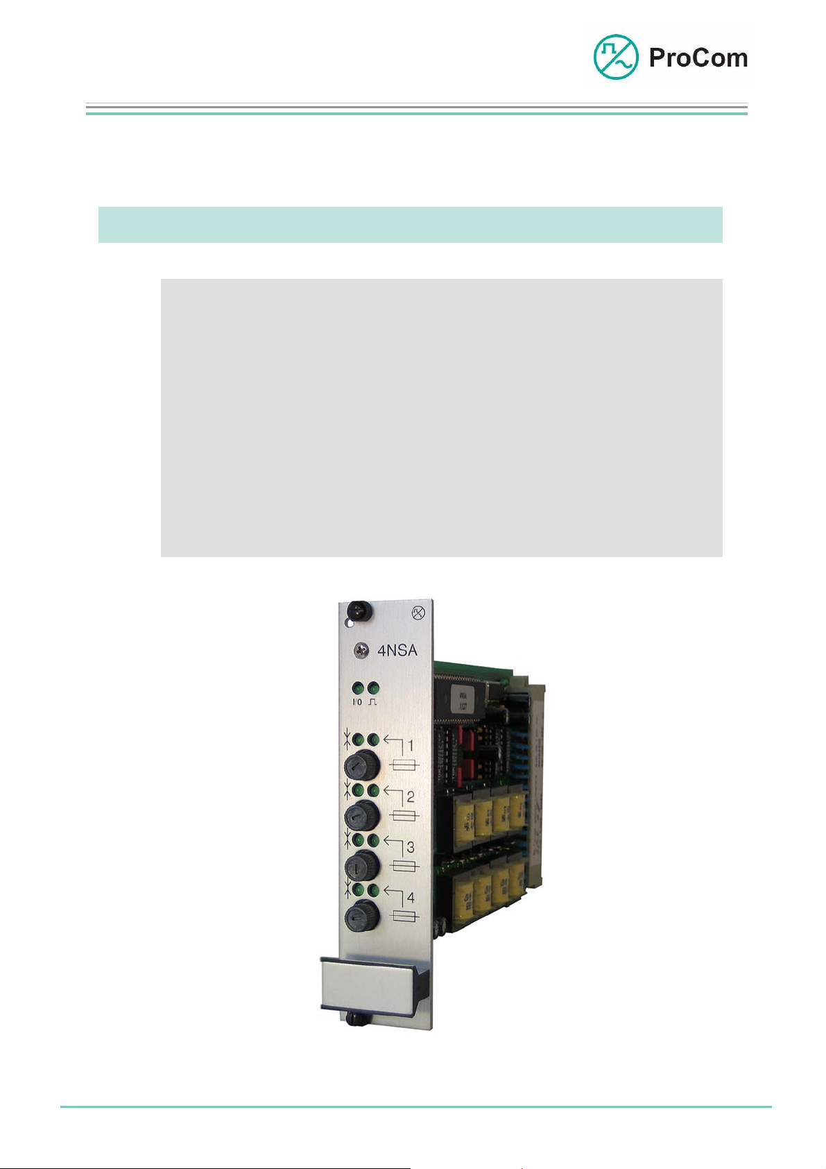
4NSA
LF Interface Module, 4-Wire
The low frequency (LF) interface module is designed for the switching on of 4 call
stations in four-wire technology.
At a Glance:
• Switching-on of up to four call stations
• Call station monitoring from the control unit
• Monitoring of call station voltage
• LF monitoring function (special model)
• Establishing long-distance lines
• Sending/receiving level can be regulated
• Special functions (optional)
Fig. 4NSA (L- No. 2.300)
Date:
13.03.2009
Page:
1/4
© 2008 ProCom, All rights and technical changes reserved
Author: HS Document-No.:
DB_4NSA_ 2300_01
Page 2
Data Sheet
4NSA
LF Interface Module, 4-Wire
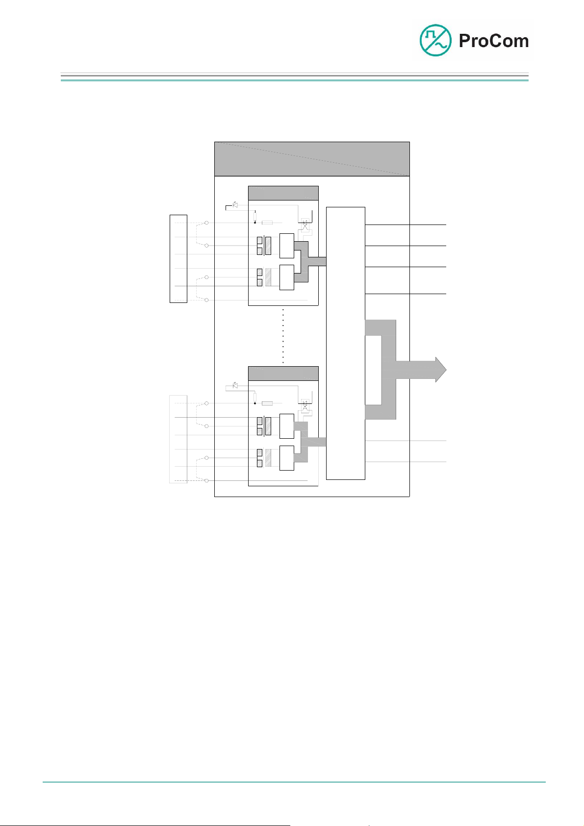
The principle functions of the 4NSA are illustrated in the following block
diagram.
C
S
a
p
l
r
e
l
c
h
S
s
t
t
a
e
t
l
i
l
o
e
n
C
S
a
p
l
r
e
l
c
h
S
s
t
t
a
e
t
l
i
l
o
e
n
Sa
Sb
La
Lb
+
Sa
Sb
La
Lb
+
Satz 1
Set 1
-48V
Satz 4
Set 4
-48V
4NSA
+
Modem
CODECCODEC
+
+
Modem
+
S
C
e
O
u
N
e
R
r
O
u
n
g
t
T
L
+5V
GND
-5V
KS
BUS
-48V
+0V
Block diagram 4NSA
The 4NSA has four independent sets. One call station with two wire pairs can be
connected to each set. If the 25 W booster amplifier of a call station is activated or
connected then two additional wires are necessary for voltage supply.
With a four-wire connection, jumpers on the backplane are necessary for the supply.
The voltage feed (-48 V) of each 4NSA set is fused with a 1.6 A fuse. If a fuse has
been triggered then the fuse LED switches off on the front plate and a message is
sent to the processor module CPU1.
The functionality of the LF module can be programmed per set using the
configuration software ICS. Control frames are sent bidirectionally over the modem
line (S
) cyclically between the 4NSA set and a call station. If a subscriber (call
a/Sb
station) is absent then an error frame is sent to the CPU and the sending/receiving
LED blinks slowly.
This monitoring function can be disabled in the ICS.
The analogue voice signal from the LF line (L
) is digitized on the 4NSA and
a/Lb
transmitted to the PCM bus.
Date:
13.03.2009
Page:
2/4
Author: HS Document-No.:
© 2008 ProCom, All rights and technical changes reserved
DB_4NSA_ 2300_01
Page 3

Data Sheet
4NSA
LF Interface Module, 4-Wire
The mode of operation is set in the configuration software ICS:
- Call station operation mode: One call station is expected as subscriber
- Master operation mode: As counterpart a 4NSA as slave is expected
- Slave operation mode: As counterpart a 4NSA as master is
expected
- No modem operation mode: The 4NSA only transmits LF signals
A slide-in attachment on the 4NSA as well as a special call station are necessary in
order to realize the LF monitoring function.
For this an audio signal is generated cyclically over the microphone of the call station
and sent to the 4NSA. If the transmission of the LF signal fails, then an error
message is generated.
This mode is activated by ticking the option in ICS.
The Symbols on the Front Plate and their Meaning:
The System Blinker
Addressing from processor taking place
I/O Input/Output
BUS output works as push-push operation with the system blinker
BUS input works as push-pull operation with the system blinker
Sending/Receiving (depending on the set)
LED lit: 4NSA sending to subscriber
LED blinking: 4NSA receiving from subscriber
LED blinking slowly: modem connection disrupted
Fuse (depending on set)
LED off: fuse has been triggered
Date:
13.03.2009
Page:
3/4
© 2008 ProCom, All rights and technical changes reserved
Author: HS Document-No.:
DB_4NSA_ 2300_01
Page 4

Data Sheet
4NSA
LF Interface Module, 4-Wire
Technical Data:
Operating Voltage: +/-5 V (control)
Operational Current (+5 V): 200 mA
Operational Current (-5 V): 4 mA
Temperature Range: 0 C to 45 °C
Weight: 300 g
Installation Height: 3HE
Installation Width: 6TE
Date:
13.03.2009
Page:
4/4
© 2008 ProCom, All rights and technical changes reserved
Author: HS Document-No.:
DB_4NSA_ 2300_01
 Loading...