

Page 1
Data Sheet
1
4NPA
LF Interface Module
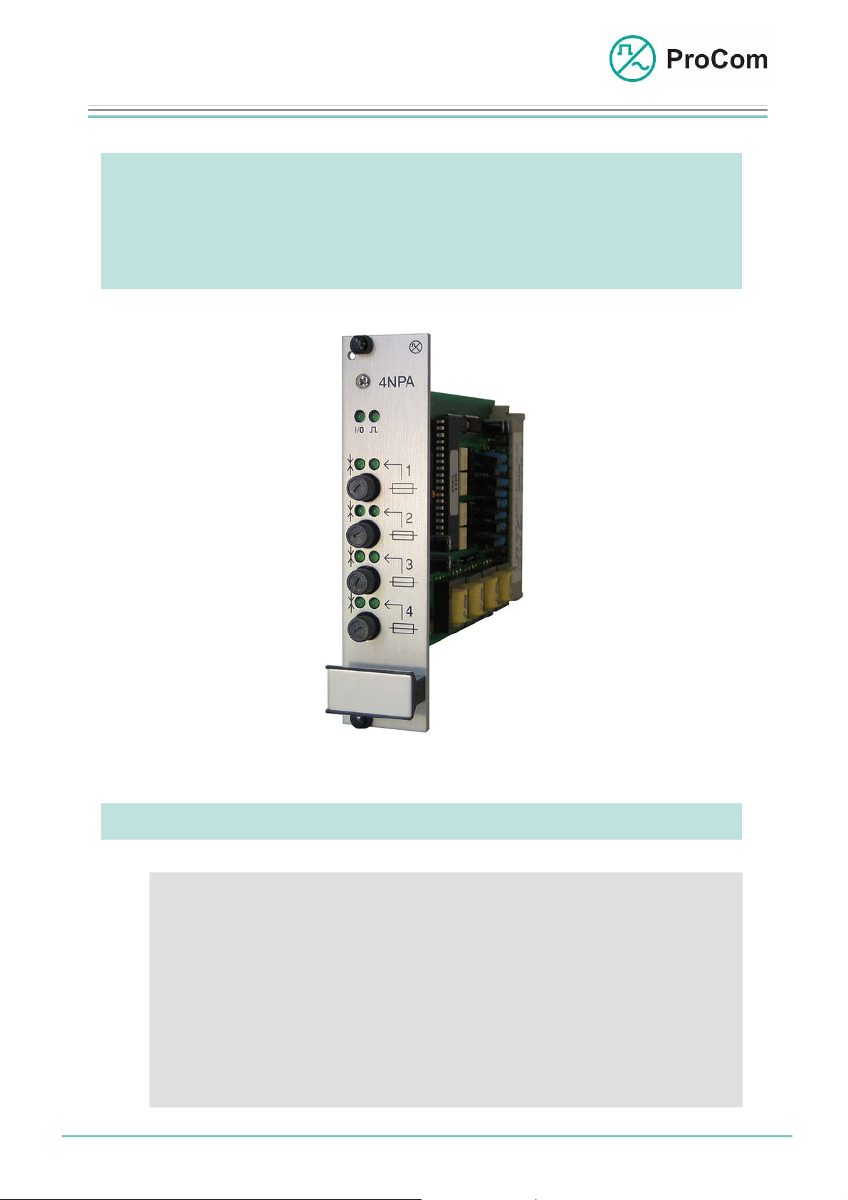
4NPA
Low Frequency Interface Module for Intercom and Public
Address Systems
Fig. 4NPA (L- No. 2.320)
At a Glance:
Date:
13.03.2009
• Low frequency (LF) control of third-party amplifiers in intercom
systems
• Connecting call stations with line control in public address
systems
• Low frequency call forwarding of/to radio module
• Low frequency interface for external low frequency sources
• Gate intercom (optional)
Page:
1/5
© 2008 ProCom, All rights and technical changes reserved
Author: HS Document-No.:
DB_4NPA_2320_01
Page 2
Data Sheet
A
A
V
1
4NPA
LF Interface Module
The DVS-21 is capable of connecting not just our own but also third-party devices. A low frequency connection and control through C and V points makes
possible the use of the module 4NPA for four devices.
In order to meet other control requirements the 24LI line module can also be
used.
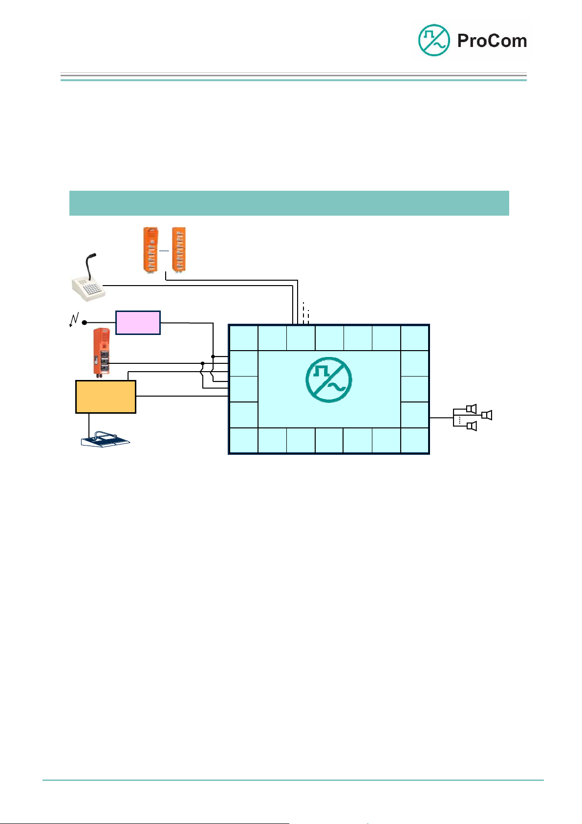
Application Description:
WPS-04
WPS-08
DTA-012 030/ 048/ 066/ 084/ 114
Radio
PABX
Radio
Modules
Third-party
Call Station
PA /
Control / ACK
Intercom
Radio
LF a / b
AWC-06
LF a / b
Carrier
Monitoring / Tone
ringing
SV01
4NP
24LI
2TW *
2TW *
CPU1 4NS
DVS-21
100
LC
LS 1
LS 2
LS n
Application examples for intercom and public address systems with 4NPA
The 4NPA can be used for various applications.
With PA applications, for public address through a line-controlled call station, in
addition to the 4NPA module also the line card 24LI and the amplifier V100 are
required. The same applies for use with a signalling system (PABX) or radio
modules.
For intercom functionality at least one further call station is necessary. This can
be another third-party call station on the same or a second 4NPA module or a
ProCom call station on a 4NSA module.
In standard use, a gate intercom is realized with ProCom call stations and the
4NSA module.
As alternative the gate intercom function can be realized with the 4NPA module and a third-party call station as gate call station. For this a ProCom call station connected over the 4NSA module and a line card 24LI are required. Here it
must be taken into account that the third-party gate call station must have control
points (-V and C points) to switch the microphone and the call station amplifier.
Further areas of application are LF control of external amplifiers as well as the LF
connection of external sources (e.g. CD player).
* TW: Twin Wire
Date:
13.03.2009
Page:
2/5
Author: HS Document-No.:
© 2008 ProCom, All rights and technical changes reserved
DB_4NPA_2320_01
Page 3

Data Sheet
1
4NPA
LF Interface Module
Function Description:
The principle functions are illustrated in the following block diagram.
24LI
Set 1
Satz 1
-48V
4NPA
+
CODEC
+
S
C
e
O
t
+5V
GND
-5V
KS
Line 1 - n
Linien 1 - n
1
2
S
S
C
p
p
n
A
r
r
-
L
e
e
L
C
c
c
h
h
S
-V
s
s
T
t
t
A
La
e
e
T
I
l
l
Lb
O
l
l
N
e
e
+
+
-
u
24LI
N
e
Line 1 - n
Linien 1 - n
1
2
S
S
C
p
p
n
A
r
r
-
L
e
e
L
C
c
c
h
h
S
-V
s
s
T
t
t
A
La
e
e
T
I
l
l
Lb
O
l
l
N
e
e
+
+
-
Set 4
Satz 4
-48V
+
CODEC
+
T
R
u
O
n
r
L
g
BUS
-48V
+0V
Block diagram 4NPA
The 4NPA has four identical sets.
The -48 V output is fused with a cut-out fuse. If this is defective then a signal is
generated through an opto-coupler.
The C point is required for switching on the call station amplifier. To use one less
line, this can be switched using a solder bridge on the backplane over the mid-a/b
output transmitter.
The microphone amplifier of a third-party call station can be switched on and off
over the V point.
These points are switched using the ICS software.
The C and -V points are control requirements for third-party call stations. They are
galvanically isolated by opto-couplers from the control circuit.
The La/b are connected to the output transformer. The incoming or outgoing analogue LF signal is converted analogue/digital by the codec.
Date:
13.03.2009
Page:
3/5
Author: HS Document-No.:
© 2008 ProCom, All rights and technical changes reserved
DB_4NPA_2320_01
Page 4

Data Sheet
1
4NPA
LF Interface Module
The Front Plate Symbols and their Meaning:
The System Blinker
Addressing from processor taking place
I/O Input/output
BUS output works as push-push operation with the system blinker
BUS input works as push-pull operation with the system blinker
Sending/receiving status (depending on set)
LED blinking: LF signal being sent
LED lit: LF signal being received
Fuse (depending on set)
LED off: Fuse has been triggered
Technical Data:
Operating Voltage: 48 V (power level)
Operating Voltage: +/-5 V (control)
Feeding Current (48 V): Max. 4x 1.5 A to the third-party call stations
Operational Current (+5V ): Max. 60 mA
LW Interfaces: 4x 300 Hz - 3400 Hz
Temperature Range: 0 °C to 45 °C
Weight: 300 g
Date:
13.03.2009
Page:
4/5
Author: HS Document-No.:
© 2008 ProCom, All rights and technical changes reserved
DB_4NPA_2320_01
Page 5

Data Sheet
1
4NPA
LF Interface Module
Installation Height: 3HE
Installation Width: 6TE
Date:
13.03.2009
Page:
5/5
Author: HS Document-No.:
© 2008 ProCom, All rights and technical changes reserved
DB_4NPA_2320_01
 Loading...